EP1742012B1 - Sensor head - Google Patents
Sensor head Download PDFInfo
- Publication number
- EP1742012B1 EP1742012B1 EP06013335A EP06013335A EP1742012B1 EP 1742012 B1 EP1742012 B1 EP 1742012B1 EP 06013335 A EP06013335 A EP 06013335A EP 06013335 A EP06013335 A EP 06013335A EP 1742012 B1 EP1742012 B1 EP 1742012B1
- Authority
- EP
- European Patent Office
- Prior art keywords
- probe head
- probe
- generator
- voltage
- electrical energy
- Prior art date
- Legal status (The legal status is an assumption and is not a legal conclusion. Google has not performed a legal analysis and makes no representation as to the accuracy of the status listed.)
- Not-in-force
Links
Images


Classifications
-
- G—PHYSICS
- G01—MEASURING; TESTING
- G01B—MEASURING LENGTH, THICKNESS OR SIMILAR LINEAR DIMENSIONS; MEASURING ANGLES; MEASURING AREAS; MEASURING IRREGULARITIES OF SURFACES OR CONTOURS
- G01B21/00—Measuring arrangements or details thereof, where the measuring technique is not covered by the other groups of this subclass, unspecified or not relevant
- G01B21/02—Measuring arrangements or details thereof, where the measuring technique is not covered by the other groups of this subclass, unspecified or not relevant for measuring length, width, or thickness
- G01B21/04—Measuring arrangements or details thereof, where the measuring technique is not covered by the other groups of this subclass, unspecified or not relevant for measuring length, width, or thickness by measuring coordinates of points
- G01B21/047—Accessories, e.g. for positioning, for tool-setting, for measuring probes
-
- G—PHYSICS
- G01—MEASURING; TESTING
- G01B—MEASURING LENGTH, THICKNESS OR SIMILAR LINEAR DIMENSIONS; MEASURING ANGLES; MEASURING AREAS; MEASURING IRREGULARITIES OF SURFACES OR CONTOURS
- G01B5/00—Measuring arrangements characterised by the use of mechanical techniques
- G01B5/004—Measuring arrangements characterised by the use of mechanical techniques for measuring coordinates of points
- G01B5/008—Measuring arrangements characterised by the use of mechanical techniques for measuring coordinates of points using coordinate measuring machines
- G01B5/012—Contact-making feeler heads therefor
-
- H—ELECTRICITY
- H02—GENERATION; CONVERSION OR DISTRIBUTION OF ELECTRIC POWER
- H02K—DYNAMO-ELECTRIC MACHINES
- H02K7/00—Arrangements for handling mechanical energy structurally associated with dynamo-electric machines, e.g. structural association with mechanical driving motors or auxiliary dynamo-electric machines
- H02K7/18—Structural association of electric generators with mechanical driving motors, e.g. with turbines
- H02K7/1807—Rotary generators
- H02K7/1823—Rotary generators structurally associated with turbines or similar engines
-
- G—PHYSICS
- G01—MEASURING; TESTING
- G01B—MEASURING LENGTH, THICKNESS OR SIMILAR LINEAR DIMENSIONS; MEASURING ANGLES; MEASURING AREAS; MEASURING IRREGULARITIES OF SURFACES OR CONTOURS
- G01B2210/00—Aspects not specifically covered by any group under G01B, e.g. of wheel alignment, caliper-like sensors
- G01B2210/58—Wireless transmission of information between a sensor or probe and a control or evaluation unit
Definitions
- the invention relates to a probe according to claim 1, which is particularly suitable for a self-powered, battery-less operation.
- Tactile systems are used, for example, for determining the position of workpieces that are used in material processing machines, for. B. milling machines are clamped.
- These touch probes often include a stationary transceiver unit mounted on a stationary element of the material processing machine and a relatively mobile part, often referred to as a probe.
- the probe is usually attached to a movable element of the material processing machine, such as a milling spindle.
- the probe comprises a deflectable from a rest position stylus, or a deflectable probe element, which generates a switching signal from its rest position out at a deflection.
- Under the rest position of the probe element is a position of the probe element understood in which it has no contact with a workpiece. Upon contact of the probe element with the workpiece, the probe element is deflected out of its rest position.
- the corresponding switching signal is transmitted from the probe as an electromagnetic signal, in particular as an infrared signal, to the stationary transmitter-receiver unit.
- the output signals of the probe system are evaluated to determine the occurrence of switching signals (ie a deflection of the probe element).
- a cable connection between the probe and the stationary transmitter-receiver unit is therefore often not.
- Such a probe often has its power supply to a DC power source in the form of one or more batteries. There is a constant desire to increase the availability of such touch probes, which is why it is attempted to maximize the service life of the DC sources.
- a battery-powered probe is specified in which the life of the batteries to be extended by various measures, which ultimately improves the availability of the corresponding probe because of less downtime due to spent batteries.
- the probe next to a stylus comprises an electrical circuit, which are assigned, inter alia, a sensor unit, a CPU (Central Processing Unit) and a transmission stage.
- the probe has a generator of electrical energy for supplying power to said elements of the circuit.
- an electrical signal can be triggered by the sensor unit, which is convertible in the transmission stage into an emitable electromagnetic signal. This signal is then receivable by a stationary transceiver unit.
- the probe comprises a voltage converter, at the output of which an output voltage can be generated which is greater than the voltage applied to the voltage converter input voltage, wherein the output voltage for powering the transmission stage is used. In this way, optimal utilization of the electrical energy generated in the probe is possible.
- fluid is meant, for example, a gas, in particular air, or compressed air.
- a liquid such as a cooling liquid, as used for example in machine tools, can be used.
- the generator of electrical energy may include a turbomachine, which drives about a generator.
- the turbomachine is designed as a turbine.
- the turbine can advantageously be designed so that the fluid flows parallel to the axis of a rotating component, which is often designed as an impeller, or alternatively orthogonal (in the tangential direction) thereto.
- the turbine has a diagonal flow direction. That is, the fluid experiences a flow direction that has a tangential and axial directional component with respect to the axis of rotation of the rotating component.
- the probe has an energy storage, in particular for storing the generated electrical energy.
- an energy store may be, for example, a rechargeable accumulator or a buffer capacitor.
- buffer capacitors can here in an advantageous Such double-layer capacitors, also known as electrochemical double layer capacitors (EDLC) called capacitors, such as those sold under the brand names Goldcaps, Supercaps or Ultracaps.
- EDLC electrochemical double layer capacitors
- the energy generated can also be stored by mechanical means, such as by a spring or in the form of rotational energy of the rotating component of the turbomachine, which then works as a flywheel. This stored mechanical energy can later be converted into electrical energy.
- the invention also includes a probe without energy storage, in which then during the measuring operation of the generator of electrical energy is in operation.
- the rotating component may be mounted with a rolling bearing in the probe or by a sliding bearing, wherein the rotating component may be configured as a plastic part or as an aluminum part, which has a low coefficient of friction, so that advantageously in the construction of plastic a sliding bearing (as a bore in Pivot point of the rotating component) can be used.
- the storage can be lubricated by the fluid itself.
- gas for. As compressed air, a very low-friction air bearing can be used to support the rotating component in the probe.
- magnets are arranged on the rotating component of the turbomachine, which magnets can be designed, for example, as permanent magnets or electromagnets and opposed to stationary electrically conductive windings, for example in the form of a wire winding.
- the magnets which may for example be designed as permanent magnets or electromagnets, are integrated in the rotating component, in particular an impeller.
- the magnets may be arranged so that they do not protrude from the outer contour of the rotating component.
- At least one of the magnets is arranged so that the connecting line of the two poles has a direction component parallel to the axis of rotation of the rotating component.
- the field lines from the two poles of a magnet arranged in the rotating component with a directional component emerge from the magnet parallel to the axis of rotation of the rotating component.
- the stationary electrically conductive windings may be formed approximately in the form of a wire winding.
- the probe is configured so that an input voltage applied to the voltage converter corresponds to the output voltage of the generator of electrical energy or the output voltage of the energy store for storing the generated electrical energy.
- the probe can also be used when the generator of electrical energy is switched off.
- the output voltage at the energy storage is transformable by the voltage converter, so that the available use time is extended.
- the probe is configured such that during the operation of the generator of electrical energy, the power generated can be fed to both the energy storage and the consumers, so the sensor unit or the CPU or the transmission stage.
- the probe without any time delay immediately after the impeller is charged with the fluid to start its operation.
- the recharging time of the energy storage device then plays no role, since it is charged in parallel with the supply of the sensor unit, the CPU or the transmission stage.
- an electronic device can be provided in the probe that automatically opens a by-pass to the sensor unit, the CPU, or the transmission stage for part of the generated current at not fully charged energy storage. The then excessively generated power is used to charge the energy storage.
- the probe is constructed so that the effluent from the generator of electrical energy fluid, such as air, for cleaning a measuring point is used.
- the effluent from the generator of electrical energy fluid such as air
- corresponding flow channels are then provided in the probe, which direct the fluid to the measuring point without an unacceptably high pressure loss occurs.
- the fact that the outflowing fluid, such as the air, is not passed directly into the environment, but through the flow channels is also achieved with advantage that the operation of the generator of electrical energy is very quiet.
- the flow channels then act sound-absorbing.
- a receiving stage which can receive electromagnetic signals from a fixed transmitter-receiver unit and then causes corresponding reactions in the probe.
- the response to the received command is limited only to the functionality of enabling or disabling the probe.
- the activation is achieved by switching on the pressurized fluid, in particular by applying compressed air, to the probe.
- the button is then deactivated again, whereby, when using an energy store in the probe, depending on the installed storage capacity, a corresponding period can pass until the final deactivation.
- the generator of electrical energy comprises a turbine with an impeller rotatable about an axis, wherein magnets are attached to the impeller of the turbine, the stationary electrically conductive turns with axial distance opposite. Accordingly, there is an air gap between the magnets and the windings, which, relative to the axis of the impeller, has an axial extent. The air gap between the magnet and the impeller is thus advantageously located on one end face of the impeller.
- the solution according to the invention therefore makes it possible to increase the availability of a touch probe, or it can reduce standstill or set-up times. Because the probe can be designed so that it works completely self-sufficient energy, so that a change of batteries is not necessary at any time. The electrical energy generated in the probe is very well utilized.
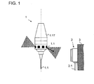
- a probe 1 is shown, which can be clamped by means of a clamping cone 1.17 in a machine tool.
- a cylindrical stylus 1.1 is provided on the probe 1, which has a probing ball at one end.
- the touch probe comprises a receiver unit 2, which is fixed to an immovable component 3 of the machine tool, so that therefore the probe head 1 is movable relative to the receiver unit 2, ie, relative to this.
- receiving elements 1.2 are distributed over the circumference of the probe 1 are provided, which are each secured offset by 60 ° along a circumferential line on the probe 1.
- electromagnetic signals in this case infrared signals, can be transmitted, which can be received by the receiver unit 2.
- FIG. 2 is a perspective view of the probe 1 in partial section without clamping cone 1.17 shown.
- the probe 1 comprises a cap 1.16, which has a fastening thread 1.161, to which the clamping cone 1.17 can be screwed. Furthermore, 1.16 four compressed air supply 1.162 are provided in the cap, which are as oblique holes through the wall the cap 1.16 are executed. Furthermore, the cap 1.16 has a central bore 1.163.
- Turbomachine 1.41 configured turbomachine comprises as a rotating component according to the FIG. 2 an impeller 1411, wherein the impeller is rotatable about an axis A, and in particular with a rolling bearing 1.412 relative to a fixed pin 1413 is rotatably mounted.
- the pin 1.413 rests in turn in the central bore 1.163 of the cap 1.16.
- the generator 1.42 consists of stationary electrically conductive windings, here in the form of windings 1.421 made of wire, in particular copper wire, and four magnets 1.422, which are integrated in the impeller 1.411.
- the magnets 1.422 are configured in all embodiments as permanent magnets.
- the usual symbolic representation for the generator 1.4 of electrical energy has been chosen for this, although in the exemplary embodiment shown there is no wave between the turbine 1.41 and the generator 1.42. Accordingly, 1.41 magnets 1.42 are fixed on the impeller 1.411 of the turbine, the stationary electrically conductive windings 1421 with axial distance, relative to the axis A of the impeller 1.411, opposite each other.
- a buffer capacitor 1.6 which is configured in the embodiment shown as a double-layer capacitor and is known under the brand name Goldcap. Such a buffer capacitor 1.6 can store comparatively much electrical energy at relatively low voltage.
- FIG. 2 Further down in the FIG. 2 is a circuit board to see 1.3, on which various electronic components of a circuit S are mounted.
- the probe 1 is clamped with its clamping cone 1.17 in a machine tool, which in turn is supplied with compressed air.
- the compressed air as a pressurized fluid, is fed through the clamping cone 1.17 in the compressed air supply 1.162.
- the compressed air is redirected so that it tangentially and with an axial direction component obliquely on the outer circumference of the impeller 1.411 and this thus set in rotation.
- an electrical voltage and an electric current are then produced in the windings 1421, that is, electrical energy is generated. This is used to charge the buffer capacitor 1.6.
- the switching on of the compressed air for flowing through the probe 1 is at the same time also the triggering event which activates the probe 1.
- the compressed air supply is switched off, so that it can not interfere with the measurement.
- the energy stored in the buffer capacitor 1.6 is used to supply the electronic components in the probe 1. If then the stylus 1.1 is deflected, ultimately, the deposition of a corresponding signal from the probe 1 to the receiver unit 2 is effected.
- FIG. 3 a further design variant of the probe according to the invention is shown.
- the turbine 1.41 is configured so that the compressed air has a tangential flow direction.
- the cap 1.16 'compressed air supply - not shown in detail in the figures -, which are aligned so that the compressed air flows tangentially to the impeller 1.411'.
- These holes are distributed at four points over the circumference of the cap 1.16 'and the impeller 1.411'.
- the probe 1 is shown in longitudinal section. Although also in the probe 1 according to FIG. 4 Flow channels are provided, which are configured such that the effluent from the turbine 1.41 fluid is usable for cleaning a measuring point, these flow channels are in the FIG. 4 not in the respective cutting planes and thus not visible.
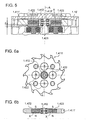
- FIG. 5 is a detail view of the longitudinal section according to FIG. 4 in the area of the impeller 1411 'and the windings 1421 shown.
- the pin 1413 'integral part of the cap 1.16' As well as in the construction according to FIG. 2 are here also attached to the impeller 1.411 'magnets 1.422, which are opposed to the stationary electrically conductive windings 1.421 with axial distance. In the FIG. 5 the distance is dimensioned with the symbol z.
- FIG. 6a is a plan view of the impeller 1.411 'shown.
- the impeller 1411 ' comprises thirteen blades.
- the impeller 1.411 ' is fed tangentially at four points distributed over the circumference compressed air. So that vibration conditions are avoided, the number of blades was chosen so that it is not integer divisible by the number of places where the compressed air is supplied.
- four magnets 1.422 are integrated in the impeller 1.411 '. The magnets 1.422 are installed in the impeller 1.411 'so that they do not protrude from the outer contour, or the end faces of the impeller 1.411'.
- the poles of the magnets 1.422 each have to the end face of the impeller 1.411 ', wherein circumferentially adjacent magnets 1.422 each have a reverse pole orientation (see also Fig. 6b ). In the execution according to FIG. 2 By the way, such an arrangement of the magnets 1422, as well as their pole orientation, is likewise present.
- a connecting line X of the poles N, S of the magnets 1.422 has a direction component parallel to the axis A of the impeller 1411, 1411 '.
- the connecting lines X are parallel to the axis A.
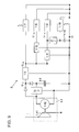
- the circuit S comprises the generator 1.4 of electrical energy consisting of the turbine 1.41 and the generator 1.42.
- the generator 1.4 of electrical energy is established. So that at high speed of the impeller 1.411 no unacceptably high DC voltage U 1.4 is formed, an overload protection circuit 1.15 is provided.
- the buffer capacitor 1.6 is charged. The negative pole of the generator 1.42 is connected to ground.
- the buffer capacitor 1.6 serves for the power supply of, inter alia, a sensor unit 1.8, a CPU 1.9 and a transmission stage 1.7.
- the circuit S comprises an RC-screening circuit, consisting of a resistor 1.13 and a capacitor 1.14 for supplying a receiving stage 1.18.
- the switching on of the probe can be effected exclusively by switching on the compressed air, instead of by setting a switch-on signal from the receiver unit 2.
- a voltage converter 1.5 is connected between the generator 1.4 of electrical energy or the buffer capacitor 1.6 and the transmission stage 1.7.
- the circuit S comprises two voltage limiters 1.11, 1.12, which supply output voltages U 1.11 , U 1.12 , which simultaneously serve as input voltage for the sensor unit 1.8 or for the CPU 1.9, respectively.
- a digital signal is generated in the sensor unit 1.8 (change of a voltage level from high to low). This signal is forwarded to the CPU 1.9 and further processed there. The further processed by the CPU signal is then passed to the transmission stage 1.7, which generates the transmission signal in the form of electromagnetic radiation or signals.
- the electromagnetic signals are formed as infrared signals, but it can also be used, for example, radio signals.
- the signals are received by the stationary transceiver unit 2. Inside the receiver unit 2, the infrared signals are converted into electrical signals and processed. Finally, the processed electrical signals arrive via a cable 2.1 in a stationary sequential electronics, where they are further processed.
- the DC voltage U 1.4 may fall below a value that is necessary for the operation of the probe 1 after a certain period of operation.
- the transmission stage requires 1.7 for proper operation, an input voltage U 1.5 of more than 5 V, in the presented embodiment, the operating target voltage for the transmission stage 1.7 at 5.5 V.
- the touch probe can continue to operate even with relatively low DC voltage U 1.4 . As a result, the possible operating time of the probe 1 is increased.
- the voltage converter 1.5 ensures that the voltage U 1.5 is at least 5 V. Therefore, it is also ensured that the input voltage U 1.12 of the sensor unit 1.8 can be reduced to the required 2.8 V by the voltage limiter 1.12.
- the DC voltage U 1.4 both at the voltage converter 1.5 and at a further voltage converter 1.5 'to.
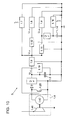
- FIG. 9 a further variant of the circuit S is shown.
- a voltage regulator 1.15 ' is used to protect against overload. This makes it possible for the generated current to be fed to both the energy store 1.6 and the sensor unit 1.8, the CPU 1.9 and the transmitting stage 1.7 during the generation of electrical energy. This can ensure that the sensor unit 1.8, the CPU 1.9 and the transmission stage 1.7 can work immediately after switching on the compressed air. A delay by the charging process of the buffer capacitor 1.6 is then excluded. On the other hand, by the operation of the turbine 1.41 and the generator 1.42 so much power is generated that in addition to the supply of the sensor unit 1.8, the CPU 1.9 and the transmission stage 1.7 and the buffer capacitor 1.6 can be charged controlled by the voltage regulator 1.15 '.
- FIG. 10 a further variant of the circuit S is shown.
- Parallel to the buffer capacitor 1.6 here is a control 1.19 connected.
- the control element 1.19 sets a short-circuit transistor 1.20 in a current-permeable state so that the windings 1421 of the generator 1.42 are short-circuited. In this way, the load is increased for the generator 1.42.
- This has the consequence that the speed of the impeller 1.411, 1.411 'is reduced.
- the maximum speed of the impeller 1.411, 1.411 ' can be limited, or it can be too high speeds of the impeller 1.411, 1.411' avoided.
- a so-called SEPIC element can also be used for the same purpose.
- the SEPIC element has the property that the predetermined output voltage is not changed in the upward direction, that is, if an output voltage of 5.5 V is specified for a SEPIC element, this voltage is not undershot if the corresponding input voltage is lower than 5.5V, but it will not be exceeded if the corresponding input voltage is greater than 5.5V. This behavior is advantageous because it results in a reduction of the power loss, or to increase the efficiency of the circuit S.
Landscapes
- Physics & Mathematics (AREA)
- General Physics & Mathematics (AREA)
- Engineering & Computer Science (AREA)
- Power Engineering (AREA)
- Connection Of Motors, Electrical Generators, Mechanical Devices, And The Like (AREA)
- Measurement Of Length, Angles, Or The Like Using Electric Or Magnetic Means (AREA)
- Surgical Instruments (AREA)
- Arrangements For Transmission Of Measured Signals (AREA)
- Electrical Discharge Machining, Electrochemical Machining, And Combined Machining (AREA)
- Length Measuring Devices With Unspecified Measuring Means (AREA)
Abstract
Description
Die Erfindung betrifft einen Tastkopf gemäß dem Anspruch 1, welcher insbesondere für einen energieautarken, batterielosen Betrieb geeignet ist.The invention relates to a probe according to
Tastsysteme werden beispielsweise zur Positionsbestimmung von Werkstücken verwendet, die in Material bearbeitenden Maschinen, z. B. Fräsmaschinen, eingespannt sind. Diese Tastsysteme weisen häufig eine stationäre Sender-Empfängereinheit auf, welche an einem ortfesten Element der Material bearbeitenden Maschine befestigt ist und ein relativ dazu bewegliches bzw. mobiles Teil, welches häufig als Tastkopf bezeichnet wird. Der Tastkopf ist meist an einem beweglichen Element der Material bearbeitenden Maschine, etwa an einer Frässpindel angebracht. Dabei umfasst der Tastkopf einen aus einer Ruheposition auslenkbaren Taststift, bzw. ein auslenkbares Tastelement, welches bei einer Auslenkung aus seiner Ruheposition heraus ein Schaltsignal erzeugt. Unter der Ruheposition des Tastelementes wird eine Position des Tastelementes verstanden, in der es keinen Kontakt mit einem Werkstück hat. Bei Kontakt des Tastelementes mit dem Werkstück wird das Tastelement aus seiner Ruheposition heraus ausgelenkt.Tactile systems are used, for example, for determining the position of workpieces that are used in material processing machines, for. B. milling machines are clamped. These touch probes often include a stationary transceiver unit mounted on a stationary element of the material processing machine and a relatively mobile part, often referred to as a probe. The probe is usually attached to a movable element of the material processing machine, such as a milling spindle. In this case, the probe comprises a deflectable from a rest position stylus, or a deflectable probe element, which generates a switching signal from its rest position out at a deflection. Under the rest position of the probe element is a position of the probe element understood in which it has no contact with a workpiece. Upon contact of the probe element with the workpiece, the probe element is deflected out of its rest position.
Bei so genannten kabellosen Tastsystemen wird das entsprechende Schaltsignal vom Tastkopf als elektromagnetisches Signal, insbesondere als Infrarotsignal, an die stationäre Sender-Empfängereinheit übertragen. In dieser werden die Ausgangssignale des Tastsystems ausgewertet, um das Auftreten von Schaltsignalen (also eine Auslenkung des Tastelementes) festzustellen. Eine Kabelverbindung zwischen Tastkopf und der stationären Sender-Empfängereinheit besteht also häufig nicht.In so-called wireless touch probes, the corresponding switching signal is transmitted from the probe as an electromagnetic signal, in particular as an infrared signal, to the stationary transmitter-receiver unit. In this the output signals of the probe system are evaluated to determine the occurrence of switching signals (ie a deflection of the probe element). A cable connection between the probe and the stationary transmitter-receiver unit is therefore often not.
Ein derartiger Tastkopf weist häufig zu dessen Energieversorgung eine Gleichstromquelle in Form von einer oder mehrerer Batterien auf. Es besteht der permanente Wunsch die Verfügbarkeit von derartigen Tastsystemen zu erhöhen, weshalb versucht wird die Standzeit der Gleichstromquellen zu maximieren.Such a probe often has its power supply to a DC power source in the form of one or more batteries. There is a constant desire to increase the availability of such touch probes, which is why it is attempted to maximize the service life of the DC sources.
In der
In der Druckschrift
In den Druckschriften
Der Erfindung liegt unter anderem die Aufgabe zugrunde, einen Tastkopf zu schaffen, bei welchem die Verfügbarkeit eines Tastsystems erhöht wird, welcher mit minimalem Wartungsaufwand betrieben werden kann, wobei eine verbesserte Nutzung der erzeugten elektrischen Energie ermöglicht wird.It is inter alia an object of the invention to provide a probe in which the availability of a probe system is increased, which can be operated with minimal maintenance, thereby enabling an improved utilization of the generated electrical energy.
Diese Aufgabe wird erfindungsgemäß durch einen Tastkopf mit den Merkmalen des Anspruches 1 gelöst.This object is achieved by a probe with the features of
Demnach umfasst der Tastkopf neben einem Taststift eine elektrische Schaltung, der unter anderem eine Sensoreinheit, eine CPU (Central Processing Unit) und eine Sendestufe zugeordnet sind. Darüber hinaus weist der Tastkopf einen Erzeuger von elektrischer Energie zur Energieversorgung der genannten Elemente der Schaltung auf. Bei einer Auslenkung des Taststifts ist von der Sensoreinheit ein elektrisches Signal auslösbar, welches in der Sendestufe in ein aussendbares elektromagnetisches Signal umwandelbar ist. Dieses Signal ist dann von einer stationären Sende- Empfängereinheit empfangbar. Ferner umfasst der Tastkopf einen Spannungswandler, an dessen Ausgang eine Ausgangsspannung erzeugbar ist, die größer ist als die am Spannungswandler anliegende Eingangsspannung, wobei die Ausgangsspannung zur Energieversorgung der Sendestufe dient. Auf diese Weise ist eine optimale Ausnutzung der erzeugten elektrischen Energie im Tastkopf möglich.Accordingly, the probe next to a stylus comprises an electrical circuit, which are assigned, inter alia, a sensor unit, a CPU (Central Processing Unit) and a transmission stage. In addition, the probe has a generator of electrical energy for supplying power to said elements of the circuit. In a deflection of the stylus, an electrical signal can be triggered by the sensor unit, which is convertible in the transmission stage into an emitable electromagnetic signal. This signal is then receivable by a stationary transceiver unit. Furthermore, the probe comprises a voltage converter, at the output of which an output voltage can be generated which is greater than the voltage applied to the voltage converter input voltage, wherein the output voltage for powering the transmission stage is used. In this way, optimal utilization of the electrical energy generated in the probe is possible.
Unter Fluid ist hier beispielsweise ein Gas zu verstehen, insbesondere Luft, bzw. Druckluft. Alternativ dazu kann als Fluid aber auch eine Flüssigkeit, etwa eine Kühlflüssigkeit, wie sie beispielsweise in Werkzeugmaschinen verwendet wird, benutzt werden.By fluid is meant, for example, a gas, in particular air, or compressed air. Alternatively, as fluid but also a liquid, such as a cooling liquid, as used for example in machine tools, can be used.
Der Erzeuger von elektrischer Energie kann eine Strömungsmaschine umfassen, welche etwa einen Generator antreibt. Mit Vorteil ist die Strömungsmaschine als eine Turbine ausgestaltet. Dabei kann die Turbine mit Vorteil so ausgestaltet sein, dass das Fluid parallel zur Achse eines rotierenden Bauteils, welches häufig als Laufrad ausgestaltet ist, oder alternativ orthogonal (in tangentialer Richtung) dazu strömt. In vorteilhafter Ausgestaltung der Erfindung weist die Turbine eine diagonale Durchströmrichtung auf. Das heißt, dass das Fluid eine Strömungsrichtung erfährt, die eine tangentiale und axiale Richtungskomponente hat, bezogen auf die Drehachse des rotierenden Bauteils.The generator of electrical energy may include a turbomachine, which drives about a generator. Advantageously, the turbomachine is designed as a turbine. In this case, the turbine can advantageously be designed so that the fluid flows parallel to the axis of a rotating component, which is often designed as an impeller, or alternatively orthogonal (in the tangential direction) thereto. In an advantageous embodiment of the invention, the turbine has a diagonal flow direction. That is, the fluid experiences a flow direction that has a tangential and axial directional component with respect to the axis of rotation of the rotating component.
Mit Vorteil weist der Tastkopf einen Energiespeicher insbesondere zur Speicherung der erzeugten elektrischen Energie auf. Ein derartiger Energiespeicher kann beispielsweise ein wiederaufladbarer Akkumulator oder ein Pufferkondensator sein. Als Pufferkondensatoren können hier in vorteilhafter Weise Doppelschicht-Kondensatoren, auch elektrochemische Doppelschicht Kondensatoren (electrochemical double layer capacity (EDLC)) genannt, wie sie unter den Markennamen Goldcaps, Supercaps oder Ultracaps vertrieben werden.Advantageously, the probe has an energy storage, in particular for storing the generated electrical energy. Such an energy store may be, for example, a rechargeable accumulator or a buffer capacitor. As buffer capacitors can here in an advantageous Such double-layer capacitors, also known as electrochemical double layer capacitors (EDLC) called capacitors, such as those sold under the brand names Goldcaps, Supercaps or Ultracaps.
Alternativ dazu kann aber die erzeugte Energie auch durch mechanische Mittel gespeichert werden, etwa durch eine Feder oder in Form von Rotationsenergie des rotierenden Bauteils der Strömungsmaschine, welches dann gleichsam als Schwungrad arbeitet. Diese gespeicherte mechanische Energie kann später in elektrische Energie umgewandelt werden.Alternatively, however, the energy generated can also be stored by mechanical means, such as by a spring or in the form of rotational energy of the rotating component of the turbomachine, which then works as a flywheel. This stored mechanical energy can later be converted into electrical energy.
Die Erfindung umfasst aber auch einen Tastkopf ohne Energiespeicher, bei dem dann während des Messbetriebs der Erzeuger von elektrischer Energie in Betrieb ist.However, the invention also includes a probe without energy storage, in which then during the measuring operation of the generator of electrical energy is in operation.
Das rotierende Bauteil kann mit einem Wälzlager im Tastkopf gelagert sein oder durch ein Gleitlager, wobei das rotierende Bauteil als Kunststoffteil oder als Aluminiumteil ausgestaltet sein kann, welches einen geringen Reibungskoeffizienten aufweist, so dass mit Vorteil bei der Bauweise aus Kunststoff ein Gleitlager (als Bohrung im Drehpunkt des rotierende Bauteils) verwendet werden kann. Weiterhin kann die Lagerung durch das Fluid selbst geschmiert werden. Insbesondere bei Verwendung von Gas , z. B. Druckluft, kann ein überaus reibungsarmes Luftlager zur Lagerung des rotierenden Bauteils im Tastkopf eingesetzt werden.The rotating component may be mounted with a rolling bearing in the probe or by a sliding bearing, wherein the rotating component may be configured as a plastic part or as an aluminum part, which has a low coefficient of friction, so that advantageously in the construction of plastic a sliding bearing (as a bore in Pivot point of the rotating component) can be used. Furthermore, the storage can be lubricated by the fluid itself. In particular, when using gas, for. As compressed air, a very low-friction air bearing can be used to support the rotating component in the probe.
Gemäß einer vorteilhaften Bauweise sind an dem rotierenden Bauteil der Strömungsmaschine Magnete angeordnet, die beispielsweise als Permanentmagnete oder Elektromagnete ausgestaltet sein können und stationären elektrisch leitfähigen Windungen, etwa in Form einer Drahtwicklung, gegenüberliegen.According to an advantageous construction, magnets are arranged on the rotating component of the turbomachine, which magnets can be designed, for example, as permanent magnets or electromagnets and opposed to stationary electrically conductive windings, for example in the form of a wire winding.
Gemäß einer vorteilhaften Bauweise sind die Magnete, die beispielsweise als Permanentmagnete_oder Elektromagnete ausgestaltet sein können, in das rotierende Bauteil, insbesondere eines Laufrads, integriert angeordnet. Insbesondere können die Magnete so angeordnet sein, dass diese nicht aus der Außenkontur des rotierenden Bauteils hervorragen.According to an advantageous construction, the magnets, which may for example be designed as permanent magnets or electromagnets, are integrated in the rotating component, in particular an impeller. In particular, the magnets may be arranged so that they do not protrude from the outer contour of the rotating component.
Mit Vorteil ist zumindest einer der Magnete so angeordnet, dass die Verbindungslinie der beiden Pole eine Richtungskomponente parallel zur Drehachse des rotierenden Bauteils aufweist. Mit anderen Worten treten die Feldlinien aus den beiden Polen eines im rotierenden Bauteil angeordneten Magneten mit einer Richtungskomponente parallel zur Drehachse des rotierenden Bauteils aus dem Magnet aus.Advantageously, at least one of the magnets is arranged so that the connecting line of the two poles has a direction component parallel to the axis of rotation of the rotating component. In other words, the field lines from the two poles of a magnet arranged in the rotating component with a directional component emerge from the magnet parallel to the axis of rotation of the rotating component.
Die stationären elektrisch leitfähigen Windungen, können etwa in Form einer Drahtwicklung ausgebildet sein.The stationary electrically conductive windings may be formed approximately in the form of a wire winding.
In weiterer Ausgestaltung der Erfindung ist der Tastkopf so konfiguriert, dass eine am Spannungswandler anliegende Eingangsspannung der Ausgangsspannung des Erzeugers von elektrischer Energie oder der Ausgangsspannung des Energiespeichers zur Speicherung der erzeugten elektrischen Energie entspricht.In a further embodiment of the invention, the probe is configured so that an input voltage applied to the voltage converter corresponds to the output voltage of the generator of electrical energy or the output voltage of the energy store for storing the generated electrical energy.
Häufig ist der Tastkopf auch bei abgeschaltetem Erzeuger von elektrischer Energie verwendbar. In diesem Fall ist es dann vorteilhaft, wenn die Ausgangsspannung am Energiespeicher durch den Spannungswandler transformierbar ist, so dass die verfügbare Einsatzzeit verlängert wird.Frequently, the probe can also be used when the generator of electrical energy is switched off. In this case, it is advantageous if the output voltage at the energy storage is transformable by the voltage converter, so that the available use time is extended.
Mit Vorteil ist der Tastkopf derart konfiguriert, dass während des Betriebs des Erzeugers von elektrischer Energie der erzeugte Strom sowohl dem Energiespeicher als auch den Verbrauchern zuführbar ist, also der Sensoreinheit oder der CPU oder der Sendestufe. Auf diese Weise kann der Tastkopf ohne jegliche Zeitverzögerung sofort nachdem das Laufrad mit dem Fluid beaufschlagt ist seinen Betrieb aufnehmen. Die Aufladezeit des Energiespeichers spielt dann keine Rolle, da dieser parallel zu Versorgung der der Sensoreinheit, der CPU oder der Sendestufe aufgeladen wird. Insbesondere kann in diesem Zusammenhang im Tastkopf eine Elektronik vorgesehen sein, die automatisch bei nicht vollständig aufgeladenem Energiespeicher einen By-Pass zur Sensoreinheit, der CPU, oder der Sendestufe für einen Teil des erzeugten Stroms öffnet. Der dann noch überschüssig erzeugte Strom wird zum Laden des Energiespeichers verwendet.Advantageously, the probe is configured such that during the operation of the generator of electrical energy, the power generated can be fed to both the energy storage and the consumers, so the sensor unit or the CPU or the transmission stage. In this way, the probe without any time delay immediately after the impeller is charged with the fluid to start its operation. The recharging time of the energy storage device then plays no role, since it is charged in parallel with the supply of the sensor unit, the CPU or the transmission stage. In particular, in this context, an electronic device can be provided in the probe that automatically opens a by-pass to the sensor unit, the CPU, or the transmission stage for part of the generated current at not fully charged energy storage. The then excessively generated power is used to charge the energy storage.
In weiterer vorteilhafter Ausgestaltung der Erfindung ist der Tastkopf so konstruiert, dass das aus dem Erzeuger von elektrischer Energie ausströmende Fluid, beispielsweise Luft, zur Reinigung einer Messstelle verwendbar ist. Zu diesem Zweck sind dann im Tastkopf entsprechende Strömungskanäle vorgesehen, welche das Fluid zur Messstelle leiten, ohne dass ein unzulässig hoher Druckverlust auftritt. Dadurch, dass das ausströmende Fluid, beispielsweise die Luft, nicht direkt in die Umgebung geführt wird, sondern durch die Strömungskanäle wird zudem mit Vorteil erreicht, dass der Betrieb des Erzeugers von elektrischer Energie sehr leise ist. Die Strömungskanäle wirken dann nämlich schalldämpfend.In a further advantageous embodiment of the invention, the probe is constructed so that the effluent from the generator of electrical energy fluid, such as air, for cleaning a measuring point is used. For this purpose, corresponding flow channels are then provided in the probe, which direct the fluid to the measuring point without an unacceptably high pressure loss occurs. The fact that the outflowing fluid, such as the air, is not passed directly into the environment, but through the flow channels is also achieved with advantage that the operation of the generator of electrical energy is very quiet. The flow channels then act sound-absorbing.
Herkömmliche Tastköpfe verfügen häufig über eine Empfangsstufe, welche elektromagnetische Signale von einer ortsfesten Sender-Empfängereinheit empfangen kann und dann entsprechende Reaktionen im Tastkopf hervorruft. Häufig ist die Reaktion auf den empfangenen Befehl lediglich die Funktionalität des Aktivierens bzw. Deaktivierens des Tastkopfes beschränkt. In einer bevorzugten Ausgestaltung der Erfindung wird die Aktivierung (Einschalten) durch Aufschalten des mit Druck beaufschlagten Fluids, insbesondere durch Aufschalten von Druckluft, auf den Tastkopf erreicht. Durch Ausschalten der Druckluft wird dann der Taster wieder deaktiviert, wobei bei Verwendung eines Energiespeichers im Tastkopf je nach installierter Speicherkapazität ein entsprechender Zeitraum bis zur endgültigen Deaktivierung vergehen kann. Durch den erfindungsgemäßen Tastkopf kann nun in vorteilhafter Ausgestaltung auf eine Empfangsstufe im Tastkopf verzichtet werden.Conventional probes often have a receiving stage, which can receive electromagnetic signals from a fixed transmitter-receiver unit and then causes corresponding reactions in the probe. Often, the response to the received command is limited only to the functionality of enabling or disabling the probe. In a preferred embodiment of the invention, the activation (switching on) is achieved by switching on the pressurized fluid, in particular by applying compressed air, to the probe. By switching off the compressed air, the button is then deactivated again, whereby, when using an energy store in the probe, depending on the installed storage capacity, a corresponding period can pass until the final deactivation. By means of the probe according to the invention, a receiving stage in the probe can now be dispensed with in an advantageous embodiment.
In vorteilhafter Ausgestaltung des Tastkopfes umfasst der Erzeuger von elektrischer Energie eine Turbine mit einem um eine Achse drehbaren Laufrad, wobei am Laufrad der Turbine Magnete befestigt sind, die stationären elektrisch leitfähigen Windungen mit axialem Abstand gegenüberliegen. Demnach befindet sich zwischen den Magneten und den Windungen ein Luftspalt der eine, bezogen auf die Achse des Laufrads, axiale Ausdehnung aufweist. Der Luftspalt zwischen den Magneten und dem Laufrad befindet sich also mit Vorteil an einer Stirnseite des Laufrads. Durch diese Anordnung ist eine äußerst kompakte Bauweise des Tastkopfes möglich. Nachdem die elektrisch leitfähigen Windungen stationär, also unbewegt, sind, wird überdies eine sehr wartungsarme bzw. gänzlich wartungsfreie Konstruktion erreicht.In an advantageous embodiment of the probe, the generator of electrical energy comprises a turbine with an impeller rotatable about an axis, wherein magnets are attached to the impeller of the turbine, the stationary electrically conductive turns with axial distance opposite. Accordingly, there is an air gap between the magnets and the windings, which, relative to the axis of the impeller, has an axial extent. The air gap between the magnet and the impeller is thus advantageously located on one end face of the impeller. By this arrangement is an extremely compact design of the probe possible. After the electrically conductive windings are stationary, so unmoved, a very low maintenance or completely maintenance-free construction is also achieved.
Durch die erfindungsgemäße Lösung kann also die Verfügbarkeit eines Tastsystems erhöht werden, bzw. es können Stillstands- oder Rüstzeiten reduziert werden. Denn der Tastkopf kann so ausgestaltet werden, dass dieser völlig energieautark arbeitet, so dass ein Wechseln von Batterien zu keinem Zeitpunkt notwendig ist. Dabei wird die im Tastkopf erzeugte elektrische Energie sehr gut ausgenutzt.The solution according to the invention therefore makes it possible to increase the availability of a touch probe, or it can reduce standstill or set-up times. Because the probe can be designed so that it works completely self-sufficient energy, so that a change of batteries is not necessary at any time. The electrical energy generated in the probe is very well utilized.
Vorteilhafte Ausbildungen der Erfindung entnimmt man den abhängigen Ansprüchen.Advantageous embodiments of the invention will remove the dependent claims.
Weitere Einzelheiten und Vorteile des erfindungsgemäßen Tastkopfs ergeben sich aus der nachfolgenden Beschreibung von Ausführungsbeispielen anhand der beiliegenden Figuren.Further details and advantages of the probe according to the invention will become apparent from the following description of exemplary embodiments with reference to the accompanying figures.
Es zeigen die
Figur 1- eine schematische Darstellung des Tastsystems,
Figur 2- eine perspektivische Ansicht eines erfindungsgemäßen Tastkopfes,
Figur 3- eine perspektivische Ansicht eines erfindungsgemäßen Tastkopfes gemäß einer Konstruktionsvariante,
- Figur 4
- eine Schnittdarstellung des Tastkopfes gemäß der Konstruktionsvariante,
- Figur 5
- ein vergrößertes Detail der Schnittdarstellung des Tastkopfes gemäß der Konstruktionsvariante,
- Figur 6a
- eine Draufsicht auf das Laufrad gemäß der Konstruktionsvariante,
- Figur 6b
- eine Schnittdarstellung durch ein Laufrad gemäß der Konstruktionsvariante,
- Figur 7
- einen schematischer Schaltungsplan einer elektrischen Schaltung des Tastkopfes,
- Figur 8
- einen schematischer Schaltungsplan einer elektrischen Schaltung des Tastkopfes gemäß einer zweiten Variante,
- Figur 9
- einen schematischer Schaltungsplan einer elektrischen Schaltung des Tastkopfes gemäß einer dritten Variante,
- Figur 10
- einen schematischer Schaltungsplan einer elektrischen Schaltung des Tastkopfes gemäß einer vierten Variante.
- FIG. 1
- a schematic representation of the probe system,
- FIG. 2
- a perspective view of a probe head according to the invention,
- FIG. 3
- a perspective view of a probe according to the invention according to a design variant,
- FIG. 4
- a sectional view of the probe according to the design variant,
- FIG. 5
- an enlarged detail of the sectional view of the probe according to the design variant,
- FIG. 6a
- a plan view of the impeller according to the design variant,
- FIG. 6b
- a sectional view through an impeller according to the design variant,
- FIG. 7
- a schematic circuit diagram of an electrical circuit of the probe,
- FIG. 8
- 2 shows a schematic circuit diagram of an electrical circuit of the probe according to a second variant,
- FIG. 9
- 3 is a schematic circuit diagram of an electrical circuit of the probe according to a third variant,
- FIG. 10
- a schematic circuit diagram of an electrical circuit of the probe according to a fourth variant.
In der
Ferner umfasst das Tastsystem eine Empfängereinheit 2, welche an einem unbeweglichen Bauteil 3 der Werkzeugmaschine fixiert ist, so dass also der Tastkopf 1 gegenüber der Empfängereinheit 2 mobil, also relativ zu dieser beweglich ist.Furthermore, the touch probe comprises a
Im gezeigten Ausführungsbeispiel sind über den Umfang des Tastkopfes 1 verteilt sechs Empfangselemente 1.2 vorgesehen, die jeweils um 60° entlang einer Umfangslinie am Tastkopf 1 versetzt befestigt sind. Mit Hilfe der Empfangselemente 1.2 können elektromagnetische Signale, hier Infrarot-Signale, ausgesendet werden, welche von der Empfängereinheit 2 empfangen werden können.In the embodiment shown six receiving elements 1.2 are distributed over the circumference of the
In der
Innerhalb der Kappe 1.16 ist - wie in den
Unterhalb der Wicklungen 1.421 befindet sich ein Pufferkondensator 1.6, der im gezeigten Ausführungsbeispiel als Doppelschicht-Kondensator ausgestaltet ist und unter den Markennamen Goldcap bekannt ist. Ein derartiger Pufferkondensator 1.6 kann vergleichsweise viel elektrische Energie speichern, bei relativ geringer Spannung.Below the windings 1421 is a buffer capacitor 1.6, which is configured in the embodiment shown as a double-layer capacitor and is known under the brand name Goldcap. Such a buffer capacitor 1.6 can store comparatively much electrical energy at relatively low voltage.
Weiter unten in der
Üblicherweise ist der Tastkopf 1 mit seinem Spannkonus 1.17 in eine Werkzeugmaschine eingespannt, die ihrerseits mit Druckluft versorgt wird. Unmittelbar vor dem eigentlichen Messvorgang, wenn der Tastkopf 1 bereits in die Nähe der Messstelle verfahren wurde, wird die Messstelle durch Druckluft frei geblasen, um zu verhindern, dass herumliegende Späne oder dergleichen die Messung stören. Die Druckluft, als ein mit Druck beaufschlagtes Fluid, wird durch den Spannkonus 1.17 in die Druckluftzuführungen 1.162 geleitet. In den Druckluftzuführungen 1.162 wird die Druckluft so umgeleitet, dass diese tangential und mit einer axialen Richtungskomponente schräg auf den Außenumfang des Laufrades 1.411 trifft und dieses somit in Rotation versetzt. In diesem Zustand entsteht dann in den Wicklungen 1.421 eine elektrische Spannung und ein elektrischer Strom, das heißt es wird elektrische Energie erzeugt. Diese wird zum Aufladen des Pufferkondensators 1.6 genutzt. Das Aufschalten der Druckluft zum Durchströmen durch den Tastkopf 1 ist im Übrigen gleichzeitig auch das auslösende Ereignis, welches den Tastkopf 1 aktiviert.Usually, the
Im eigentlichen Messbetrieb, der sich unmittelbar nach dem Freiblasen anschließt wird die Druckluftzufuhr abgeschaltet, damit diese die Messung nicht stören kann. Während dieser Zeit wird die im Pufferkondensator 1.6 gespeicherte Energie zu Versorgung der elektronischen Komponenten im Tastkopf 1 verwendet. Wenn dann der Taststift 1.1 ausgelenkt wird, wird letztlich das Abzusetzen eines entsprechenden Signals vom Tastkopf 1 an die Empfängereinheit 2 bewirkt.In the actual measuring operation, which is connected immediately after blowing out, the compressed air supply is switched off, so that it can not interfere with the measurement. During this time, the energy stored in the buffer capacitor 1.6 is used to supply the electronic components in the
In der
In der
In der
In der
Somit weist eine Verbindungslinie X der Pole N, S der Magnete 1.422 eine Richtungskomponente parallel zur Achse A des Laufrads 1.411, 1.411' auf. In den gezeigten Ausführungsbeispielen liegen die Verbindungslinien X parallel zur Achse A.Thus, a connecting line X of the poles N, S of the magnets 1.422 has a direction component parallel to the axis A of the impeller 1411, 1411 '. In the embodiments shown, the connecting lines X are parallel to the axis A.
Durch die Bauweise des Tastkopfes 1 dessen Laufrad 1.411, 1.411' Magnete 1.422 aufweist, die stationären elektrisch leitfähigen Wicklungen 1.421 mit axialem Abstand z gegenüberliegen, ist es nunmehr möglich eine überaus kompakte Konstruktion zu erreichen, die wenig Bauraum beansprucht. Dieser Effekt wird auch noch dadurch unterstützt, dass das Laufrad 1.411, 1.411' als Teil der Turbine 1.41 mit den Magneten 1.422 auch Teile des Generators 1.42 umfasst.Due to the design of the
Durch diese Konstruktion ist es weiterhin möglich zu einer hermetisch dichten Bauweise zu gelangen. Denn es kann so eine Wellendurchführung für den Generator 1.42 vermieden werden. Somit kann beispielsweise von der Leiterplatte 1.3 mit den darauf befindlichen Elektronikkomponenten und von den eigentlichen Sensorelementen (im unteren Teil des Tastkopfes 1 in
In der
Sobald nach Abschalten der Druckluft die Turbine 1.41 und der Generator 1.42 wieder stehen, dient der Pufferkondensator 1.6 zur Energieversorgung von unter anderem einer Sensoreinheit 1.8, einer CPU 1.9 und einer Sendestufe 1.7. Ferner umfasst die Schaltung S eine RC-Siebungsschaltung, bestehend aus einem Widerstand 1.13 und einem Kondensator 1.14 zur Versorgung einer Empfangsstufe 1.18. In Abwandlung der Schaltung S kann auf die Empfangsstufe 1.18 verzichtet werden. Insbesondere kann das Anschalten des Tastkopfes ausschließlich durch Aufschalten der Druckluft erfolgen, statt durch das Absetzen eines Einschaltsignals von der Empfängereinheit 2.As soon as the turbine 1.41 and the generator 1.42 are switched off again after the compressed air has been switched off, the buffer capacitor 1.6 serves for the power supply of, inter alia, a sensor unit 1.8, a CPU 1.9 and a transmission stage 1.7. Furthermore, the circuit S comprises an RC-screening circuit, consisting of a resistor 1.13 and a capacitor 1.14 for supplying a receiving stage 1.18. In a modification of the circuit S can be dispensed with the receiving stage 1.18. In particular, the switching on of the probe can be effected exclusively by switching on the compressed air, instead of by setting a switch-on signal from the
Zwischen dem Erzeuger 1.4 von elektrischer Energie bzw. dem Pufferkondensator 1.6 und der Sendestufe 1.7 ist ein Spannungswandler 1.5 geschaltet.Between the generator 1.4 of electrical energy or the buffer capacitor 1.6 and the transmission stage 1.7, a voltage converter 1.5 is connected.
Gemäß der
Wenn im Messbetrieb der Taststift 1.1 ausgelenkt wird, so wird in der Sensoreinheit 1.8 ein digitales Signal erzeugt (Änderung eines Spannungspegels von High auf Low). Dieses Signal wird an die CPU 1.9 weitergeleitet und dort weiterverarbeitet. Das durch die CPU weiterverarbeitete Signal wird sodann an die Sendestufe 1.7 geleitet, welche das Sendesignal in Form von elektromagnetischen Strahlen bzw. Signalen erzeugt. Im gezeigten Ausführungsbeispiel sind die elektromagnetischen Signale als Infrarot-Signale ausgebildet, es können aber beispielsweise auch Funksignale verwendet werden. Die Signale werden von der stationären Sende-Empfangseinheit 2 empfangen. Im Inneren der Empfängereinheit 2 werden die Infrarot-Signale in elektrische Signale umgewandelt und aufbereitet. Letztlich gelangen die aufbereiteten elektrischen Signale über ein Kabel 2.1 in eine ortsfeste Folgeelektronik, wo sie weiterverarbeitet werden.If the stylus 1.1 is deflected during measuring operation, a digital signal is generated in the sensor unit 1.8 (change of a voltage level from high to low). This signal is forwarded to the CPU 1.9 and further processed there. The further processed by the CPU signal is then passed to the transmission stage 1.7, which generates the transmission signal in the form of electromagnetic radiation or signals. In the illustrated embodiment, the electromagnetic signals are formed as infrared signals, but it can also be used, for example, radio signals. The signals are received by the
Bei abgeschalteter Druckluft kann nach einer gewissen Betriebszeit die Gleichspannung U1.4 unter einen Wert fallen, der für den Betrieb des Tastkopfes 1 notwendig ist. Beispielsweise benötigt die Sendestufe 1.7 für einen einwandfreien Betrieb eine Eingangsspannung U1.5 von mehr als 5 V, im vorgestellten Ausführungsbeispiel liegt die Betriebssollspannung für die Sendestufe 1.7 bei 5,5 V. Durch den Spannungswandler 1.5 wird nun die Gleichspannung U1.4, die in dieser Phase des Ausführungsbeispiels 4,5 V betragen soll auf U1.5 = 5,5 V erhöht. Somit kann das Tastsystem auch mit vergleichsweise geringer Gleichspannung U1.4 weiter betrieben werden. Dadurch wird die mögliche Betriebszeit des Tastkopfs 1 erhöht.When the compressed air is switched off, the DC voltage U 1.4 may fall below a value that is necessary for the operation of the
Durch den Spannungsbegrenzer 1.12 wird die Spannung U1.5 = 5,5 V auf eine Spannung U1.12 = 2,8 V reduziert, wie sie für den Betrieb der Sensoreinheit 1.8 erforderlich ist. Neben der Funktion der Spannungsreduzierung weist der Spannungsbegrenzer 1.12 überdies die Eigenschaft auf, die am Eingang der Sensoreinheit 1.8 anliegende Spannung U1.12 zu glätten, was für das Messverhalten des Tastkopfs 1 von erheblicher Bedeutung ist.By the voltage limiter 1.12, the voltage U 1.5 = 5.5 V is reduced to a voltage U 1.12 = 2.8 V, as required for the operation of the sensor unit 1.8. In addition to the function of the voltage reduction, the voltage limiter 1.12 also has the property of smoothing the voltage U 1.12 present at the input of the sensor unit 1.8, which is of considerable importance for the measurement behavior of the
Die CPU 1.9 wird mit einer Spannung U1.11 von 2,8 V versorgt. Deshalb ist ein entsprechender Spannungsbegrenzer 1.11, welcher die Spannung U1.5 = 5,5 V auf 2,8 V reduziert, der CPU 1.9 vorgeschaltet.The CPU 1.9 is supplied with a voltage U 1.11 of 2.8 V. Therefore, a corresponding voltage limiter 1.11, which reduces the voltage U 1.5 = 5.5 V to 2.8 V, the CPU 1.9 upstream.
Durch den Spannungswandler 1.5 ist gewährleistet, dass die Spannung U1.5 mindestens 5 V beträgt. Deshalb ist auch sichergestellt, dass die Eingangsspannung U1.12 der Sensoreinheit 1.8 durch den Spannungsbegrenzer 1.12 auf die erforderlichen 2,8 V reduzierbar ist.The voltage converter 1.5 ensures that the voltage U 1.5 is at least 5 V. Therefore, it is also ensured that the input voltage U 1.12 of the sensor unit 1.8 can be reduced to the required 2.8 V by the voltage limiter 1.12.
Eine analoge Betrachtung gilt auch für die Spannungsversorgung der CPU 1.9. Auch hier ist eine Reduktion der Spannung U1.5 auf erforderliche Eingangsspannung U1.11 von 2,8 V durch den Spannungsbegrenzer 1.11 stets erreichbar. Der Spannungsbegrenzer 1.11 hat auch die Eigenschaft, die Spannung U1.11 gegenüber der Spannung U1.5 zu glätten, was für den Betrieb der CPU 1.9 von großem Vorteil ist.An analogous consideration also applies to the power supply of the CPU 1.9. Again, a reduction of the voltage U 1.5 to required input voltage U 1.11 of 2.8 V by the voltage limiter 1.11 always reachable. The voltage limiter 1.11 also has the property of smoothing the voltage U 1.11 with respect to the voltage U 1.5 , which is of great advantage for the operation of the CPU 1.9.
In einem weiteren Ausführungsbeispiel der Schaltung S liegt gemäß der
Die Reduzierung führt zu einer Glättung der Eingangsspannung U1.11. Gleichzeitig gewährleistet der andere Spannungswandler 1.5 eine Erhöhung der Spannung auf U1.5 = 5,5 V. Durch diese Anordnung kann der Gesamtwirkungsgrad der Schaltung S erhöht werden.The reduction leads to a smoothing of the input voltage U 1.11 . At the same time, the other voltage converter 1.5 ensures an increase of the voltage to U 1.5 = 5.5 V. By this arrangement, the overall efficiency of the circuit S can be increased.
In der
In der
Alternativ zu dem oben beschriebenen Spannungswandler 1.5 kann auch zum gleichen Zweck ein so genanntes SEPIC-Element verwendet werden. Das SEPIC-Element hat die Eigenschaft, dass die vorgegebene Ausgangsspannung auch nach oben hin nicht verändert wird, das heißt, wenn bei einem SEPIC-Element eine Ausgangsspannung von 5,5 V vorgegeben ist, wird diese Spannung nicht unterschritten, wenn die entsprechende Eingangsspannung kleiner als 5,5 V ist, sie wird aber auch nicht überschritten, wenn die entsprechende Eingangsspannung größer als 5,5 V ist. Dieses Verhalten ist vorteilhaft, weil daraus eine Reduzierung der Verlustleistung, bzw. zur Erhöhung des Wirkungsgrades der Schaltung S resultiert.As an alternative to the voltage converter 1.5 described above, a so-called SEPIC element can also be used for the same purpose. The SEPIC element has the property that the predetermined output voltage is not changed in the upward direction, that is, if an output voltage of 5.5 V is specified for a SEPIC element, this voltage is not undershot if the corresponding input voltage is lower than 5.5V, but it will not be exceeded if the corresponding input voltage is greater than 5.5V. This behavior is advantageous because it results in a reduction of the power loss, or to increase the efficiency of the circuit S.
Claims (14)
- A probe head (1) comprising a stylus (1.1), wherein the probe head (1) comprises- a sensor unit (1.8),- a CPU (1.9) and- a transmission stage (1.7) as well as- a generator (1.4) of electrical energy for the energy supply of the sensor unit (1.8), the CPU (1.9) and the transmission stage (1.7),wherein, in response to a deflection of the stylus (1.1), the sensor unit (1.8) can trigger an electrical signal, which can be converted into an electromagnetic signal in the transmission stage (1.7) and
the generator (1.4) of electrical energy can be actuated by means of a pressurized fluid, wherein the probe head (1) further comprises a voltage converter (1.5) at the output of which an output voltage (U1.5) can be generated, which is greater than the input voltage (U1.4) applied to the voltage converter (1.5), wherein the output voltage (U1.5) serves for the energy supply of the transmission stage (1.7). - The probe head (1) according to claim 1, wherein the probe head (1) comprises an energy storage (1.6) for storing the generated electrical energy.
- The probe head (1) according to claim 2, wherein the energy storage (1.6) is a capacitor.
- The probe head (1) according to claim 2 or 3, wherein the input voltage (U1.4) applied to the voltage converter (1.5) corresponds- to the output voltage (U1.4) of the generator (1.4) of electrical energy or- to the output voltage (U1.4) of the energy storage (1.6).
- The probe head (1) according to one of the preceding claims, wherein said probe head (1) is configured such that the generated current can be supplied to the energy storage (1.6) as well as to the sensor unit (1.8) or to the CPU (1.9) or to the transmission stage (1.7) during the operation of the generator (1.4) of electrical energy.
- The probe head (1) according to one of the preceding claims, wherein the generator (1.4) of electrical energy comprises a turbo engine (1.41).
- The probe head (1) according to claim 6, wherein the turbo engine (1.41) is embodied as a turbine.
- The probe head (1) according to claim 7, wherein the turbine (1.41) is configured such that the fluid encompasses a tangential direction of flow.
- The probe head (1) according to claim 6, 7 or 8, wherein magnets (1.422), in particular permanent magnets, which are located opposite to stationary electrically conductive windings (1.421), are arranged on a rotating component of the turbo engine (1.41).
- The probe head (1) according to claim 8, 9 or 10, wherein the generator (1.4) of electrical energy comprises a turbine (1.41) comprising a rotor disk (1.411, 1.411'), which can be rotated about an axis (A), wherein magnets (1.422), which are located opposite to stationary electrically conductive windings (1.421) at an axial distance (z), are fastened to the rotor disk (1.411, 1.411') of the turbine (1.41).
- The probe head (1) according to claim 10, wherein the connecting line (X) of the poles (N, S) of one of the magnets (1.422) encompasses a directional component parallel to the axis (A) of the rotor blade (1.411, 1.411').
- The probe head (1) according to one of claims 6 to 11, wherein said probe head (1) encompasses a control electronics (1.19), by means of which the stationary electrically conductive windings (1.421) can be short-circuited for limiting the speed of the turbo engine (1.41).
- The probe head (1) according to one of the preceding claims, wherein the fluid, in particular compressed air, flows out of the generator (1.4) of electrical energy and corresponding flow ducts in the probe head (1) are configured such that the escaping fluid can be used to clean a measuring point.
- The probe head (1) according to one of the preceding claims, wherein said probe head (1) is configured such that an activation of the probe head (1) can be attained by applying the pressurized fluid to the probe head (1).
Applications Claiming Priority (3)
| Application Number | Priority Date | Filing Date | Title |
|---|---|---|---|
| DE102005031994 | 2005-07-08 | ||
| DE102006024491A DE102006024491A1 (en) | 2005-07-08 | 2006-05-26 | Milling machine measuring probe head has probe rod linked to sensor creating electromagnetic output with power from fluid driven turbine generator |
| DE102006024492A DE102006024492A1 (en) | 2005-07-08 | 2006-05-26 | Milling machine measuring probe head has probe rod linked to sensor creating electromagnetic output with power from fluid driven turbine generator |
Publications (3)
| Publication Number | Publication Date |
|---|---|
| EP1742012A2 EP1742012A2 (en) | 2007-01-10 |
| EP1742012A3 EP1742012A3 (en) | 2010-02-17 |
| EP1742012B1 true EP1742012B1 (en) | 2010-11-03 |
Family
ID=36791615
Family Applications (2)
| Application Number | Title | Priority Date | Filing Date |
|---|---|---|---|
| EP06013334A Not-in-force EP1742011B1 (en) | 2005-07-08 | 2006-06-28 | Sensor head |
| EP06013335A Not-in-force EP1742012B1 (en) | 2005-07-08 | 2006-06-28 | Sensor head |
Family Applications Before (1)
| Application Number | Title | Priority Date | Filing Date |
|---|---|---|---|
| EP06013334A Not-in-force EP1742011B1 (en) | 2005-07-08 | 2006-06-28 | Sensor head |
Country Status (4)
| Country | Link |
|---|---|
| US (1) | US7464483B2 (en) |
| EP (2) | EP1742011B1 (en) |
| AT (2) | ATE487107T1 (en) |
| DE (2) | DE502006008214D1 (en) |
Families Citing this family (16)
| Publication number | Priority date | Publication date | Assignee | Title |
|---|---|---|---|---|
| JP2009053052A (en) * | 2007-08-27 | 2009-03-12 | Mitsutoyo Corp | Shape measuring machine and its probe |
| DE102007054838A1 (en) * | 2007-11-16 | 2009-05-20 | Dr. Johannes Heidenhain Gmbh | Touch probe and method for operating a touch probe |
| JP4291394B1 (en) * | 2008-03-12 | 2009-07-08 | ファナック株式会社 | Contact-type measuring device |
| EP2112461B1 (en) | 2008-04-24 | 2012-10-24 | Hexagon Metrology AB | Self-powered measuring probe |
| JP5262630B2 (en) * | 2008-12-01 | 2013-08-14 | 富士通株式会社 | Clock generation circuit having self-test circuit |
| JP6010045B2 (en) | 2011-01-19 | 2016-10-19 | レニショウ パブリック リミテッド カンパニーRenishaw Public Limited Company | Analog measuring probe and operating method for machine tool apparatus |
| DE102011084755A1 (en) | 2011-03-24 | 2012-09-27 | Dr. Johannes Heidenhain Gmbh | Probe and method of operating a probe |
| DE102011100467B3 (en) * | 2011-05-02 | 2012-07-05 | Carl Zeiss Industrielle Messtechnik Gmbh | Measuring head for a coordinate measuring machine for determining spatial coordinates on a measuring object |
| EP2920549B1 (en) * | 2012-11-14 | 2020-01-08 | Renishaw Plc. | Method and apparatus for measuring a workpiece with a machine tool |
| US20150125230A1 (en) * | 2013-11-01 | 2015-05-07 | Lockheed Martin Corporation | Apparatus for an on-tool power supply |
| EP3524587A1 (en) | 2015-08-21 | 2019-08-14 | SABIC Global Technologies B.V. | Process for producing btx from a c5-c12 hydrocarbon mixture |
| DE102016012726A1 (en) * | 2016-10-24 | 2018-04-26 | Blum-Novotest Gmbh | Measuring system for measuring on tools in a machine tool |
| EP3688404B1 (en) * | 2017-09-29 | 2023-06-07 | Mitutoyo Corporation | Compact measurement device configuration for integrating complex circuits |
| US12179276B2 (en) * | 2021-01-20 | 2024-12-31 | Iscar, Ltd. | Rotary cutting tool having an energy harvesting arrangement |
| DE102021128314A1 (en) | 2021-10-29 | 2023-05-04 | Blum-Novotest Gmbh | Concentricity monitoring modules and concentricity monitoring methods for a tool that is to be rotated during operation |
| US11821811B2 (en) * | 2022-02-04 | 2023-11-21 | Pratt & Whitney Canada Corp. | Fluid measurement system for an aircraft gas turbine engine and method for operating same |
Family Cites Families (23)
| Publication number | Priority date | Publication date | Assignee | Title |
|---|---|---|---|---|
| US4339714A (en) * | 1978-07-07 | 1982-07-13 | Rolls Royce Limited | Probe having passive means transmitting an output signal by reactive coupling |
| CH660421A5 (en) * | 1982-12-18 | 1987-04-15 | Maag Zahnraeder & Maschinen Ag | TOOTH MEASURING PROBE FOR GEAR MEASURING MACHINE. |
| US4513507A (en) * | 1983-09-02 | 1985-04-30 | Bendix Automation Company | Contact sensing probe for a measuring apparatus |
| GB8503355D0 (en) * | 1985-02-09 | 1985-03-13 | Renishaw Plc | Sensing surface of object |
| US4654956A (en) * | 1985-04-16 | 1987-04-07 | Protocad, Inc. | Drill apparatus for use with computer controlled plotter |
| DE68916463T2 (en) * | 1988-04-12 | 1994-11-17 | Renishaw Plc | Signal transmission system for machine tools, inspection machines and the like. |
| DE3813949A1 (en) * | 1988-04-26 | 1989-11-09 | Heidenhain Gmbh Dr Johannes | DEVICE FOR INDUCTIVE SIGNAL TRANSMISSION IN PROBE HEADS |
| JPH03223602A (en) * | 1990-01-29 | 1991-10-02 | Tokyo Seimitsu Co Ltd | Automatic measuring probe |
| DE69127277T2 (en) * | 1990-03-23 | 1998-01-29 | Geotronics Ab | ANALOGUE DEVIATION SENSOR |
| FR2715222B1 (en) * | 1994-01-14 | 1996-04-05 | Giat Ind Sa | Self-powered meter. |
| US5564872A (en) * | 1994-03-21 | 1996-10-15 | Veil; Wilfried | Implement for machine tools and process for generating electric power in one such implement |
| DE4424225A1 (en) * | 1994-07-09 | 1996-01-11 | Zeiss Carl Fa | Probe for coordinate measuring machines |
| IT1309248B1 (en) * | 1999-05-13 | 2002-01-16 | Marposs Spa | SYSTEM TO DETECT LINEAR DIMENSIONS OF MECHANICAL PIECES, WITH UNIT OF RECEIVING SIGNALS VIA ETHER |
| SE523573C2 (en) * | 2000-12-22 | 2004-04-27 | Atlas Copco Tools Ab | Compressed air powered machine tool. |
| ATE407389T1 (en) * | 2001-02-02 | 2008-09-15 | Renishaw Plc | MEASURING PROBE FOR A MACHINE TOOL CONFIGURABLE BY BENDING THE PROBE |
| JP2003170328A (en) * | 2001-11-30 | 2003-06-17 | Toshiba Mach Co Ltd | Tool, tool holder, and machine tool |
| JP4959111B2 (en) * | 2002-04-20 | 2012-06-20 | レニショウ パブリック リミテッド カンパニー | Machine conforming structure |
| DE10303551A1 (en) * | 2003-01-29 | 2004-08-12 | Dr. Johannes Heidenhain Gmbh | Method for transmitting control commands from a transmission element to a probe |
| GB0308149D0 (en) * | 2003-04-09 | 2003-05-14 | Renishaw Plc | Probe for sensing the position of an object |
| GB0325353D0 (en) * | 2003-10-30 | 2003-12-03 | Renishaw Plc | Machine adaptation |
| DE102004003487A1 (en) | 2004-01-23 | 2005-08-11 | Dr. Johannes Heidenhain Gmbh | Touch probe and method for operating a touch probe |
| DE102004011730A1 (en) * | 2004-03-05 | 2005-09-22 | Carl Zeiss Industrielle Messtechnik Gmbh | Probe for a coordinate measuring machine |
| DE102006054978A1 (en) * | 2006-11-22 | 2008-05-29 | Dr. Johannes Heidenhain Gmbh | probe |
-
2006
- 2006-06-28 DE DE502006008214T patent/DE502006008214D1/en active Active
- 2006-06-28 AT AT06013334T patent/ATE487107T1/en active
- 2006-06-28 AT AT06013335T patent/ATE487108T1/en active
- 2006-06-28 DE DE502006008215T patent/DE502006008215D1/en active Active
- 2006-06-28 EP EP06013334A patent/EP1742011B1/en not_active Not-in-force
- 2006-06-28 EP EP06013335A patent/EP1742012B1/en not_active Not-in-force
- 2006-07-10 US US11/484,272 patent/US7464483B2/en not_active Expired - Fee Related
Also Published As
| Publication number | Publication date |
|---|---|
| EP1742011A3 (en) | 2010-02-17 |
| US20070006473A1 (en) | 2007-01-11 |
| ATE487107T1 (en) | 2010-11-15 |
| US7464483B2 (en) | 2008-12-16 |
| DE502006008215D1 (en) | 2010-12-16 |
| EP1742011B1 (en) | 2010-11-03 |
| ATE487108T1 (en) | 2010-11-15 |
| EP1742011A2 (en) | 2007-01-10 |
| EP1742012A2 (en) | 2007-01-10 |
| DE502006008214D1 (en) | 2010-12-16 |
| EP1742012A3 (en) | 2010-02-17 |
Similar Documents
| Publication | Publication Date | Title |
|---|---|---|
| EP1742012B1 (en) | Sensor head | |
| EP1878535B1 (en) | Sensor system for machine tools | |
| DE69928895T2 (en) | High-speed drilling spindle with a reciprocating ceramic shaft and a double-grip centrifugal chuck | |
| EP2049302B1 (en) | Rotary table mounting and drive device | |
| EP3028804B1 (en) | Transmission device, in particular for energy and/or signal transmission | |
| DE102011105306A1 (en) | Portable tool with wireless data transmission | |
| EP0972868A2 (en) | Bearing assembly for an open-end spinning machine | |
| EP1207299A2 (en) | Wind turbine with magnetic bearing | |
| WO2007093465A1 (en) | Electrical machine having an apparatus for avoiding damaging bearing currents, and a corresponding method | |
| DE102012201347A1 (en) | Electrical machine e.g. permanent-magnet synchronous motor for motor vehicle, has control unit that is arranged for detecting fault in the excitation magnetic field and for controlling actuator in case of error | |
| DE102018215796A1 (en) | Position detection system and method for detecting a movement of a machine | |
| DE10302531B4 (en) | Measuring device and measuring method for electric motors | |
| EP2843784A2 (en) | Drive circuit for air bearing motors | |
| DE102009041340A1 (en) | Scalping device for use in scalping machine for machine processing of e.g. rod shaped designed semi-finished product, has component engaging gear that rotates with scalping head, by implementing component movement regarding to head | |
| DE102016119821A1 (en) | motor spindle | |
| DE102006024492A1 (en) | Milling machine measuring probe head has probe rod linked to sensor creating electromagnetic output with power from fluid driven turbine generator | |
| DE102006024491A1 (en) | Milling machine measuring probe head has probe rod linked to sensor creating electromagnetic output with power from fluid driven turbine generator | |
| EP2699916B1 (en) | Monitoring apparatus for a doubly-fed asynchronous machine | |
| DE102023126766A1 (en) | Device and method for determining a state variable of an engine bearing | |
| DE102016208341A1 (en) | Steam turbine plant with magnetic bearing | |
| DE102010005557A1 (en) | Workpiece desk for machine tool used for machining workpieces by lathing, has top plate integrated in substructure and including separate rotary drive for driving receiving plate for machining workpiece mounted on receiving plate by lathing | |
| EP1557639B1 (en) | Probing system and method for operating it | |
| EP4137699B1 (en) | Vacuum device and method for operating same | |
| WO2008098846A2 (en) | Electric direct drive device, particularly for a turntable | |
| DE102017118771A1 (en) | Output station for actuating a flap on an aircraft wing and aircraft with such output stations |
Legal Events
| Date | Code | Title | Description |
|---|---|---|---|
| PUAI | Public reference made under article 153(3) epc to a published international application that has entered the european phase |
Free format text: ORIGINAL CODE: 0009012 |
|
| AK | Designated contracting states |
Kind code of ref document: A2 Designated state(s): AT BE BG CH CY CZ DE DK EE ES FI FR GB GR HU IE IS IT LI LT LU LV MC NL PL PT RO SE SI SK TR |
|
| AX | Request for extension of the european patent |
Extension state: AL BA HR MK YU |
|
| 17P | Request for examination filed |
Effective date: 20091126 |
|
| PUAL | Search report despatched |
Free format text: ORIGINAL CODE: 0009013 |
|
| AK | Designated contracting states |
Kind code of ref document: A3 Designated state(s): AT BE BG CH CY CZ DE DK EE ES FI FR GB GR HU IE IS IT LI LT LU LV MC NL PL PT RO SE SI SK TR |
|
| AX | Request for extension of the european patent |
Extension state: AL BA HR MK RS |
|
| GRAP | Despatch of communication of intention to grant a patent |
Free format text: ORIGINAL CODE: EPIDOSNIGR1 |
|
| RIC1 | Information provided on ipc code assigned before grant |
Ipc: G01B 5/012 20060101AFI20100723BHEP |
|
| GRAS | Grant fee paid |
Free format text: ORIGINAL CODE: EPIDOSNIGR3 |
|
| GRAA | (expected) grant |
Free format text: ORIGINAL CODE: 0009210 |
|
| AKX | Designation fees paid |
Designated state(s): AT BE BG CH CY CZ DE DK EE ES FI FR GB GR HU IE IS IT LI LT LU LV MC NL PL PT RO SE SI SK TR |
|
| AK | Designated contracting states |
Kind code of ref document: B1 Designated state(s): AT BE BG CH CY CZ DE DK EE ES FI FR GB GR HU IE IS IT LI LT LU LV MC NL PL PT RO SE SI SK TR |
|
| REG | Reference to a national code |
Ref country code: GB Ref legal event code: FG4D Free format text: NOT ENGLISH |
|
| REG | Reference to a national code |
Ref country code: CH Ref legal event code: NV Representative=s name: ICB INGENIEURS CONSEILS EN BREVETS SA Ref country code: CH Ref legal event code: EP |
|
| REG | Reference to a national code |
Ref country code: IE Ref legal event code: FG4D Free format text: LANGUAGE OF EP DOCUMENT: GERMAN |
|
| REF | Corresponds to: |
Ref document number: 502006008215 Country of ref document: DE Date of ref document: 20101216 Kind code of ref document: P |
|
| REG | Reference to a national code |
Ref country code: NL Ref legal event code: VDEP Effective date: 20101103 |
|
| LTIE | Lt: invalidation of european patent or patent extension |
Effective date: 20101103 |
|
| PG25 | Lapsed in a contracting state [announced via postgrant information from national office to epo] |
Ref country code: LT Free format text: LAPSE BECAUSE OF FAILURE TO SUBMIT A TRANSLATION OF THE DESCRIPTION OR TO PAY THE FEE WITHIN THE PRESCRIBED TIME-LIMIT Effective date: 20101103 |
|
| REG | Reference to a national code |
Ref country code: IE Ref legal event code: FD4D |
|
| PG25 | Lapsed in a contracting state [announced via postgrant information from national office to epo] |
Ref country code: BG Free format text: LAPSE BECAUSE OF FAILURE TO SUBMIT A TRANSLATION OF THE DESCRIPTION OR TO PAY THE FEE WITHIN THE PRESCRIBED TIME-LIMIT Effective date: 20110203 Ref country code: FI Free format text: LAPSE BECAUSE OF FAILURE TO SUBMIT A TRANSLATION OF THE DESCRIPTION OR TO PAY THE FEE WITHIN THE PRESCRIBED TIME-LIMIT Effective date: 20101103 Ref country code: SE Free format text: LAPSE BECAUSE OF FAILURE TO SUBMIT A TRANSLATION OF THE DESCRIPTION OR TO PAY THE FEE WITHIN THE PRESCRIBED TIME-LIMIT Effective date: 20101103 Ref country code: IS Free format text: LAPSE BECAUSE OF FAILURE TO SUBMIT A TRANSLATION OF THE DESCRIPTION OR TO PAY THE FEE WITHIN THE PRESCRIBED TIME-LIMIT Effective date: 20110303 Ref country code: NL Free format text: LAPSE BECAUSE OF FAILURE TO SUBMIT A TRANSLATION OF THE DESCRIPTION OR TO PAY THE FEE WITHIN THE PRESCRIBED TIME-LIMIT Effective date: 20101103 Ref country code: LV Free format text: LAPSE BECAUSE OF FAILURE TO SUBMIT A TRANSLATION OF THE DESCRIPTION OR TO PAY THE FEE WITHIN THE PRESCRIBED TIME-LIMIT Effective date: 20101103 Ref country code: PT Free format text: LAPSE BECAUSE OF FAILURE TO SUBMIT A TRANSLATION OF THE DESCRIPTION OR TO PAY THE FEE WITHIN THE PRESCRIBED TIME-LIMIT Effective date: 20110303 Ref country code: SI Free format text: LAPSE BECAUSE OF FAILURE TO SUBMIT A TRANSLATION OF THE DESCRIPTION OR TO PAY THE FEE WITHIN THE PRESCRIBED TIME-LIMIT Effective date: 20101103 |
|
| PG25 | Lapsed in a contracting state [announced via postgrant information from national office to epo] |
Ref country code: GR Free format text: LAPSE BECAUSE OF FAILURE TO SUBMIT A TRANSLATION OF THE DESCRIPTION OR TO PAY THE FEE WITHIN THE PRESCRIBED TIME-LIMIT Effective date: 20110204 |
|
| PG25 | Lapsed in a contracting state [announced via postgrant information from national office to epo] |
Ref country code: CZ Free format text: LAPSE BECAUSE OF FAILURE TO SUBMIT A TRANSLATION OF THE DESCRIPTION OR TO PAY THE FEE WITHIN THE PRESCRIBED TIME-LIMIT Effective date: 20101103 Ref country code: EE Free format text: LAPSE BECAUSE OF FAILURE TO SUBMIT A TRANSLATION OF THE DESCRIPTION OR TO PAY THE FEE WITHIN THE PRESCRIBED TIME-LIMIT Effective date: 20101103 Ref country code: IE Free format text: LAPSE BECAUSE OF FAILURE TO SUBMIT A TRANSLATION OF THE DESCRIPTION OR TO PAY THE FEE WITHIN THE PRESCRIBED TIME-LIMIT Effective date: 20101103 Ref country code: ES Free format text: LAPSE BECAUSE OF FAILURE TO SUBMIT A TRANSLATION OF THE DESCRIPTION OR TO PAY THE FEE WITHIN THE PRESCRIBED TIME-LIMIT Effective date: 20110214 |
|
| PG25 | Lapsed in a contracting state [announced via postgrant information from national office to epo] |
Ref country code: RO Free format text: LAPSE BECAUSE OF FAILURE TO SUBMIT A TRANSLATION OF THE DESCRIPTION OR TO PAY THE FEE WITHIN THE PRESCRIBED TIME-LIMIT Effective date: 20101103 Ref country code: SK Free format text: LAPSE BECAUSE OF FAILURE TO SUBMIT A TRANSLATION OF THE DESCRIPTION OR TO PAY THE FEE WITHIN THE PRESCRIBED TIME-LIMIT Effective date: 20101103 Ref country code: PL Free format text: LAPSE BECAUSE OF FAILURE TO SUBMIT A TRANSLATION OF THE DESCRIPTION OR TO PAY THE FEE WITHIN THE PRESCRIBED TIME-LIMIT Effective date: 20101103 Ref country code: DK Free format text: LAPSE BECAUSE OF FAILURE TO SUBMIT A TRANSLATION OF THE DESCRIPTION OR TO PAY THE FEE WITHIN THE PRESCRIBED TIME-LIMIT Effective date: 20101103 |
|
| PLBE | No opposition filed within time limit |
Free format text: ORIGINAL CODE: 0009261 |
|
| STAA | Information on the status of an ep patent application or granted ep patent |
Free format text: STATUS: NO OPPOSITION FILED WITHIN TIME LIMIT |
|
| 26N | No opposition filed |
Effective date: 20110804 |
|
| REG | Reference to a national code |
Ref country code: DE Ref legal event code: R097 Ref document number: 502006008215 Country of ref document: DE Effective date: 20110804 |
|
| BERE | Be: lapsed |
Owner name: DR. JOHANNES HEIDENHAIN G.M.B.H. Effective date: 20110630 |
|
| REG | Reference to a national code |
Ref country code: FR Ref legal event code: ST Effective date: 20120229 |
|
| PG25 | Lapsed in a contracting state [announced via postgrant information from national office to epo] |
Ref country code: BE Free format text: LAPSE BECAUSE OF NON-PAYMENT OF DUE FEES Effective date: 20110630 |
|
| PG25 | Lapsed in a contracting state [announced via postgrant information from national office to epo] |
Ref country code: FR Free format text: LAPSE BECAUSE OF NON-PAYMENT OF DUE FEES Effective date: 20110630 |
|
| REG | Reference to a national code |
Ref country code: AT Ref legal event code: MM01 Ref document number: 487108 Country of ref document: AT Kind code of ref document: T Effective date: 20110628 |
|
| PG25 | Lapsed in a contracting state [announced via postgrant information from national office to epo] |
Ref country code: AT Free format text: LAPSE BECAUSE OF NON-PAYMENT OF DUE FEES Effective date: 20110628 |
|
| PG25 | Lapsed in a contracting state [announced via postgrant information from national office to epo] |
Ref country code: MC Free format text: LAPSE BECAUSE OF NON-PAYMENT OF DUE FEES Effective date: 20110630 |
|
| PG25 | Lapsed in a contracting state [announced via postgrant information from national office to epo] |
Ref country code: LU Free format text: LAPSE BECAUSE OF NON-PAYMENT OF DUE FEES Effective date: 20110628 Ref country code: CY Free format text: LAPSE BECAUSE OF FAILURE TO SUBMIT A TRANSLATION OF THE DESCRIPTION OR TO PAY THE FEE WITHIN THE PRESCRIBED TIME-LIMIT Effective date: 20101103 |
|
| PG25 | Lapsed in a contracting state [announced via postgrant information from national office to epo] |
Ref country code: TR Free format text: LAPSE BECAUSE OF FAILURE TO SUBMIT A TRANSLATION OF THE DESCRIPTION OR TO PAY THE FEE WITHIN THE PRESCRIBED TIME-LIMIT Effective date: 20101103 |
|
| PG25 | Lapsed in a contracting state [announced via postgrant information from national office to epo] |
Ref country code: HU Free format text: LAPSE BECAUSE OF FAILURE TO SUBMIT A TRANSLATION OF THE DESCRIPTION OR TO PAY THE FEE WITHIN THE PRESCRIBED TIME-LIMIT Effective date: 20101103 |
|
| PGFP | Annual fee paid to national office [announced via postgrant information from national office to epo] |
Ref country code: IT Payment date: 20190419 Year of fee payment: 14 |
|
| PGFP | Annual fee paid to national office [announced via postgrant information from national office to epo] |
Ref country code: CH Payment date: 20190619 Year of fee payment: 14 |
|
| PGFP | Annual fee paid to national office [announced via postgrant information from national office to epo] |
Ref country code: GB Payment date: 20190619 Year of fee payment: 14 |
|
| REG | Reference to a national code |
Ref country code: CH Ref legal event code: PL |
|
| GBPC | Gb: european patent ceased through non-payment of renewal fee |
Effective date: 20200628 |
|
| PG25 | Lapsed in a contracting state [announced via postgrant information from national office to epo] |
Ref country code: CH Free format text: LAPSE BECAUSE OF NON-PAYMENT OF DUE FEES Effective date: 20200630 Ref country code: LI Free format text: LAPSE BECAUSE OF NON-PAYMENT OF DUE FEES Effective date: 20200630 Ref country code: GB Free format text: LAPSE BECAUSE OF NON-PAYMENT OF DUE FEES Effective date: 20200628 |
|
| PG25 | Lapsed in a contracting state [announced via postgrant information from national office to epo] |
Ref country code: IT Free format text: LAPSE BECAUSE OF NON-PAYMENT OF DUE FEES Effective date: 20200628 |
|
| PGFP | Annual fee paid to national office [announced via postgrant information from national office to epo] |
Ref country code: DE Payment date: 20230620 Year of fee payment: 18 |
|
| REG | Reference to a national code |
Ref country code: DE Ref legal event code: R119 Ref document number: 502006008215 Country of ref document: DE |
|
| PG25 | Lapsed in a contracting state [announced via postgrant information from national office to epo] |
Ref country code: DE Free format text: LAPSE BECAUSE OF NON-PAYMENT OF DUE FEES Effective date: 20250101 |