EP1740846B1 - Fühler für verschleissanzeige für bremsbeläge - Google Patents
Fühler für verschleissanzeige für bremsbeläge Download PDFInfo
- Publication number
- EP1740846B1 EP1740846B1 EP04730626A EP04730626A EP1740846B1 EP 1740846 B1 EP1740846 B1 EP 1740846B1 EP 04730626 A EP04730626 A EP 04730626A EP 04730626 A EP04730626 A EP 04730626A EP 1740846 B1 EP1740846 B1 EP 1740846B1
- Authority
- EP
- European Patent Office
- Prior art keywords
- wear
- probe
- seating
- brake
- indicator
- Prior art date
- Legal status (The legal status is an assumption and is not a legal conclusion. Google has not performed a legal analysis and makes no representation as to the accuracy of the status listed.)
- Expired - Lifetime
Links
- 239000000523 sample Substances 0.000 title claims abstract description 39
- 239000004020 conductor Substances 0.000 claims abstract description 28
- 239000002783 friction material Substances 0.000 claims abstract description 23
- 238000010276 construction Methods 0.000 description 2
- 238000002788 crimping Methods 0.000 description 2
- 238000005520 cutting process Methods 0.000 description 2
- 238000005516 engineering process Methods 0.000 description 2
- 239000011810 insulating material Substances 0.000 description 2
- 238000000034 method Methods 0.000 description 2
- 238000000465 moulding Methods 0.000 description 2
- 239000004642 Polyimide Substances 0.000 description 1
- 230000006978 adaptation Effects 0.000 description 1
- 238000007792 addition Methods 0.000 description 1
- 238000012423 maintenance Methods 0.000 description 1
- 238000004519 manufacturing process Methods 0.000 description 1
- 239000002184 metal Substances 0.000 description 1
- 229920001721 polyimide Polymers 0.000 description 1
- 239000002861 polymer material Substances 0.000 description 1
- 238000006467 substitution reaction Methods 0.000 description 1
Images


Classifications
-
- F—MECHANICAL ENGINEERING; LIGHTING; HEATING; WEAPONS; BLASTING
- F16—ENGINEERING ELEMENTS AND UNITS; GENERAL MEASURES FOR PRODUCING AND MAINTAINING EFFECTIVE FUNCTIONING OF MACHINES OR INSTALLATIONS; THERMAL INSULATION IN GENERAL
- F16D—COUPLINGS FOR TRANSMITTING ROTATION; CLUTCHES; BRAKES
- F16D66/00—Arrangements for monitoring working conditions, e.g. wear, temperature
- F16D66/02—Apparatus for indicating wear
- F16D66/021—Apparatus for indicating wear using electrical detection or indication means
- F16D66/022—Apparatus for indicating wear using electrical detection or indication means indicating that a lining is worn to minimum allowable thickness
-
- F—MECHANICAL ENGINEERING; LIGHTING; HEATING; WEAPONS; BLASTING
- F16—ENGINEERING ELEMENTS AND UNITS; GENERAL MEASURES FOR PRODUCING AND MAINTAINING EFFECTIVE FUNCTIONING OF MACHINES OR INSTALLATIONS; THERMAL INSULATION IN GENERAL
- F16D—COUPLINGS FOR TRANSMITTING ROTATION; CLUTCHES; BRAKES
- F16D2250/00—Manufacturing; Assembly
- F16D2250/0084—Assembly or disassembly
Definitions
- the subject of the present invention is a probe for an indicator of wear of the friction material fitted to the pads of a brake, particularly to the pads of a disc brake.
- a probe for instance known from GB-A-2 115 893 .
- indicators comprising a probe and an indicator circuit are commonly used.
- the probe generally comprises a block having an aperture through it, within which a conductor wire is housed.
- the probe is housed in a recess made in the pad plate and in such a way that the wire is turned towards the brake disc.
- the block of the probe also begins to be exposed to wear.
- the block in becoming consumed, exposes the conductor wire to wear.
- a circuit is opened and this generates a warning signal directed to the user of the vehicle, relating to the state of wear of the brake pads.
- indicators of the type outlined above are not free from disadvantages. For example, it is impossible for construction of the probe and its components to be completely automated. This is because the construction provides for the steps of cutting the conductor wire to the desired length, removing the insulating material from the ends of the wire, inserting the wire into the block having an aperture through it, crimping the terminals to the ends of the wire and moulding the connector which encases the terminals.
- the operation of inserting the conductor wire axially into the aperture in the block which constitutes its seating necessarily requires that the terminals should not yet have been crimped to the ends of the wire. Because this operation is rather complex, it is necessary to make provision for it to be carried out manually, interrupting an otherwise automated cycle, with an obvious increase in time and cost.
- What is required is an indicator of the state of wear of the brake pads which can be easily produced in an automated manner. Specifically, there is a requirement for a probe the assembly of which does not require the conductor wire to be threaded into its seating by means of a movement along the axis of the seating.
- this indicator should ensure that the conductor wire does not come out of its seating and that consequently it wears at the same rate as the friction material surrounding it.
- the purpose of the present invention is to devise and make available an indicator of the state of wear of brake pads and an associated probe which meet the above-mentioned requirements and at the same time eliminate the disadvantages of the known technology.
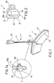
- . - figure 1 shows in isometric projection a probe of a wear-indicator of the known type and a brake pad on which it may be mounted;
- figure 1a shows a detail of figure 1 ;
- FIG. 2 shows in isometric projection a detail of the probe of the indicator according to the invention
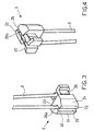
- FIG. 3 shows in isometric projection another detail of the probe of the indicator according to the invention.
- figure 4 shows in isometric projection the detail in figure 3 inverted and reversed compared with figure 3 ;
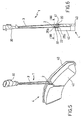
- FIG. 5 shows in isometric projection a probe according to the invention mounted on a brake pad
- figure 6 shows a section along the plane of symmetry in figure 5 ;
- FIG. 7a shows in section along the plane VII-VII in figure 6 a probe according to the invention in a first operating configuration
- FIG. 7b shows in section along the plane VII-VII in figure 6 a probe according to the invention in a second operating configuration
- FIG. 8a to 8d show four successive steps in the method of producing a probe.
- the number 1 indicates as a whole a probe for an indicator of wear of the friction material of the pads of a brake.
- the probe 1 comprises a block 2 and a conductor 3 which will be described in what follows.
- the block 2 comprises an engagement portion 20 and a wear portion 22 opposite the engagement portion 20.
- the engagement portion 20 is capable of being inserted into a recess 41 and remaining firmly housed in it until an operator takes deliberate action to remove it.
- the recess 41 is typically made in a plate 40 of a brake disc 4.
- the block 2 is produced in such a way that, once the engagement portion 20 is inserted into the recess 41, the wear portion 22 is surrounded by the friction material 42 of the pad 4.
- the wear portion 22 in turn comprises one or more wear surfaces 24 facing towards the friction face 50 of the brake.
- the wear surfaces 24 are arranged in such a way that a half-line (for example s or s' in figure 7a ) coming out perpendicularly from them meets the surface of the friction face 50.
- the seating 23 forms a path into which the wear segment 32 of the conductor 3 must fit.
- This path may be characterised conventionally as having an entrance 26a and an exit 26b opposite to it.
- the wear portion 22 also comprises a groove 25 providing access to the seating 23 and connecting the entrance 26a to the exit 26b.
- This groove 25 is formed in such a way as to allow the wear segment 32 to be in inserted into the associated seating 23 by means of a movement in a transverse direction relative to the seating 23.
- this groove 25 opens onto the wear surface 24.
- the block 2 is preferably produced from a polymer material of the polyimide type (for example Meldin ® 7001 marketed by Saint-Gobain ® ) capable of maintaining its own mechanical characteristics even at the high operating temperatures which are typically reached by the pad 4 during the braking action.
- a polymer material of the polyimide type for example Meldin ® 7001 marketed by Saint-Gobain ®
- the conductor 3 comprises means for electrical connection to an indicator circuit and a wear segment 32.
- the means for electrical connection comprise a connector 30 of known type.
- the wear segment 32 on the contrary is a length of the conductor 3 which provides electrical continuity of the circuit and which is designed to be exposed to wear together with the wear portion 22 of the block 2 within which the seating 23 is made and together with the friction material 42 which surrounds the wear portion 22.
- the conductor 3 can be inserted into its seating 23 inside the block 2, despite the presence of the terminals and the connector 30.
- the probe 1 in accordance with the invention is inserted into the recess 41 made in the plate 40 of a pad 4. In this way, the wear portion 22 of the block 2 is sunk in the friction material 42 of the pad 4.
- the braking action applied by the friction material 42 to the friction face 50 causes wear of the friction material and consequent reduction in its thickness h.
- any further wear of the friction material 42 involves simultaneous wear of the wear portion 22 of the block 2 of the probe 1.
- any further wear of the friction material 42 involves simultaneous wear of the wear segment 32 of the conductor 3 of the probe 1.
- the wear segment 32 of the conductor 3 breaks or in any case is no longer capable of ensuring the electrical continuity of the indicator circuit.
- the indicator circuit When the electrical continuity which was ensured by the integrity of the conductor 3 fails, the indicator circuit generates a warning signal directed to the user of the vehicle and regarding the state of wear of the brake pads.
- Determination of the three successive levels h', h" and h'" of wear of the friction material 42 may vary depending on specific requirements.
- the third wear level which determines the generation of the warning signal will be determined so as to reconcile the opposing requirements of utilising the full thickness of the friction material 42 and allowing a remaining mileage such as to ensure that the vehicle can be driven safely to a maintenance facility.
- the probe 1 according to the invention ensures that there is no possibility of the conductor 3 escaping from the seating 23 and that it remains intact independently of the level of wear of the friction material 42.
- connection of the probe 1 to the indicator circuit may be produced by any means suitable for providing electrical continuity of the circuit and considered adequate for the specific requirements.
Landscapes
- Engineering & Computer Science (AREA)
- General Engineering & Computer Science (AREA)
- Mechanical Engineering (AREA)
- Braking Arrangements (AREA)
Claims (9)
- Sonde (1) für einen Anzeiger des Verschleißes des Reibmaterials (42) der Klötze (4) einer Bremse, die eine Bremsscheibe (5) aufweist, umfassend:- einen Leiter (3), der mit einem Anzeigerschaltkreis verbunden werden kann und ein gerades Verschleißsegment (32) aufweist; und- einen Block (2) mit einem Eingriffsabschnitt (20), der in einen Bremsklotz (4) eingepasst werden kann; einen Verschleißabschnitt (22), der einer Reibfläche (50) der Bremsscheibe (5) zugewandt sein kann; und eine Aufnahme (23), die im Verschleißabschnitt (22) gebildet ist, wobei die Aufnahme eine Weg bildet, der einen Eingang (26a) und einen Ausgang (26b) bildet, wobei die Aufnahme derart gebildet ist, dass sie bei Verwerdung das gerade Verschleißsegment (32) des Leiters (3) in einer vorbestimmten radialen Richtung in Bezug auf die Bremsscheibe (5) enthält;bei dem der Verschleißabschnitt (22) eine Nut (25) aufweist, die Zugriff auf die Aufnahme (23) ermöglicht, wobei die Nut mit dem Eingang (26a) und dem Ausgang (26b) verbunden ist;
dadurch gekennzeichnet, dass der Eingriffsabschnitt (20) eine zweite Aufnahme umfasst, die einen Abschnitt des Leiters (3) enthält, der sich von dem Verschleißsegment (32) unterscheidet. - Sonde (1) nach Anspruch 1, bei der der Verschleißabschnitt (22) wenigstens eine Verschleißfläche (24) aufweist, die einer Reibfläche (50) der Bremse (5) zugewandt ist.
- Sonde (1) nach Anspruch 2, bei der die Nut (25), die Zugriff auf die Aufnahme (23) ermöglicht, sich auf die Verschleißfläche (24) hin öffnet.
- Sonde (1) nach Anspruch 1, weiter umfassend ein Mittel (30) zum elektrischen Verbinden mit einem Anzeigerschaltkreis.
- Sonde (1) nach Anspruch 4, bei der das Mittelt einen Verbinder (30) umfasst.
- Anzeiger des Verschleißes des Reibmaterials der Klötze einer Bremse, umfassend eine Sonde nach einem der Anspruche 1 bis 5.
- Sonde (1) nach Anspruch 1, bei der der Querschnitt der Nut (25) sich auf die Aufnahme (23) zu verjüngt und bei der die Minimalbreite der Nut (25) kleiner als der Innendurchmesser der Aufnahme (23) ist.
- Sonde (1) nach Anspruch 1, bei der der Eingriffsabschnitt (20) in eine Vertiefung (41) radial eingesetzt werden kann, die in der Platte (40) des Bremsklotzes (4) gebildet ist.
- Anzeiger des Verschleißes des Reibmaterials der Klötze einer Bremse, umfassend eine Sonde nach einem der Ansprüche 8 bis 10.
Applications Claiming Priority (1)
| Application Number | Priority Date | Filing Date | Title |
|---|---|---|---|
| PCT/IT2004/000238 WO2005106280A1 (en) | 2004-04-30 | 2004-04-30 | Probe of wear-indicator for brake pads |
Publications (2)
| Publication Number | Publication Date |
|---|---|
| EP1740846A1 EP1740846A1 (de) | 2007-01-10 |
| EP1740846B1 true EP1740846B1 (de) | 2008-12-10 |
Family
ID=34957724
Family Applications (1)
| Application Number | Title | Priority Date | Filing Date |
|---|---|---|---|
| EP04730626A Expired - Lifetime EP1740846B1 (de) | 2004-04-30 | 2004-04-30 | Fühler für verschleissanzeige für bremsbeläge |
Country Status (6)
| Country | Link |
|---|---|
| EP (1) | EP1740846B1 (de) |
| AT (1) | ATE417213T1 (de) |
| DE (1) | DE602004018394D1 (de) |
| ES (1) | ES2319528T3 (de) |
| IT (1) | ITMI20050758A1 (de) |
| WO (1) | WO2005106280A1 (de) |
Families Citing this family (4)
| Publication number | Priority date | Publication date | Assignee | Title |
|---|---|---|---|---|
| DE102008026104B4 (de) * | 2008-05-30 | 2012-02-09 | Knorr-Bremse Systeme für Nutzfahrzeuge GmbH | Einrichtung zur Verschleißerkennung eines Bremsbelages einer Scheibenbremse sowie Bremsbelag für eine Scheibenbremse |
| DE102013109183B4 (de) * | 2013-08-23 | 2017-03-23 | Pex Automotive Gmbh | Reibbelagsverschleisssensor |
| KR101977714B1 (ko) * | 2014-06-20 | 2019-05-13 | 주식회사 만도 | 브레이크 마찰 패드의 마모감지장치 |
| GB2557195A (en) * | 2016-11-30 | 2018-06-20 | Jaguar Land Rover Ltd | Controller for a braking system of a vehicle |
Family Cites Families (6)
| Publication number | Priority date | Publication date | Assignee | Title |
|---|---|---|---|---|
| DE3204305C1 (de) * | 1982-02-09 | 1983-09-29 | Leopold Kostal GmbH & Co KG, 5880 Lüdenscheid | Bremsbelagverschleiß-Überwachungsorgan |
| DE8206021U1 (de) * | 1982-03-04 | 1982-10-21 | Lucas Industries Ltd., Birmingham, West Midlands | Warnanzeigevorrichtung fuer belagverschleiss an bremsbacken |
| IT220458Z2 (it) * | 1990-06-22 | 1993-09-22 | Veglia Borletti Srl | Sensore di usura della pastiglia del freno per autoveicoli. |
| FR2697065B1 (fr) * | 1992-10-20 | 1994-12-02 | Cablage Cie Francaise | Témoin d'usure de plaquette de frein pour véhicule automobile. |
| FR2707719B1 (fr) * | 1993-07-12 | 1995-09-15 | Plastic Omnium Cie | Embout pour témoin d'usure de garniture de friction, notamment de plaquette de frein. |
| CN1111657C (zh) * | 1997-11-17 | 2003-06-18 | 住友电装株式会社 | 用于制动垫的磨损检测探头 |
-
2004
- 2004-04-30 ES ES04730626T patent/ES2319528T3/es not_active Expired - Lifetime
- 2004-04-30 DE DE602004018394T patent/DE602004018394D1/de not_active Expired - Lifetime
- 2004-04-30 AT AT04730626T patent/ATE417213T1/de not_active IP Right Cessation
- 2004-04-30 WO PCT/IT2004/000238 patent/WO2005106280A1/en not_active Application Discontinuation
- 2004-04-30 EP EP04730626A patent/EP1740846B1/de not_active Expired - Lifetime
-
2005
- 2005-04-27 IT IT000758A patent/ITMI20050758A1/it unknown
Also Published As
| Publication number | Publication date |
|---|---|
| DE602004018394D1 (de) | 2009-01-22 |
| ES2319528T3 (es) | 2009-05-08 |
| WO2005106280A1 (en) | 2005-11-10 |
| ATE417213T1 (de) | 2008-12-15 |
| ITMI20050758A1 (it) | 2005-11-01 |
| EP1740846A1 (de) | 2007-01-10 |
Similar Documents
| Publication | Publication Date | Title |
|---|---|---|
| US4869350A (en) | Wear indicator for a friction member of an automotive brake | |
| US5608376A (en) | Pad wear and pad wear indicator probe | |
| CA1245994A (en) | Brake lining wear sensor and indicator circuit | |
| US4298857A (en) | Brake wear indicator system | |
| GB2177170A (en) | Disc brake assembly having an electrical lining wear indicator | |
| US4832160A (en) | Wear indicator for a friction member of a motor-vehicle brake and friction member equipped with such an indicator | |
| JPH0559285B2 (de) | ||
| EP0992702A2 (de) | Bremsschuh mit resistivem Belagverschleisssensor | |
| CN109563897B (zh) | 磨损监控设备和具有这种磨损监控设备的盘式制动器 | |
| EP1740846B1 (de) | Fühler für verschleissanzeige für bremsbeläge | |
| GB1337358A (en) | Means for indicating brake-lining wear on vehicles | |
| US6719102B2 (en) | Wear detection probe for a braking member | |
| US3976167A (en) | Brake pad with wear indicator | |
| US4643277A (en) | Brake shoe arrangement and a method of manufacturing a brake shoe | |
| EP0610828B1 (de) | Belagverschleisssensor und Methode zur dessen Herstellung | |
| US4456098A (en) | Brake pad with electrical contacts for brake warning systems | |
| US5692585A (en) | Brake pad with a wear indicator | |
| GB2086501A (en) | Wear indicator | |
| JPH0550183U (ja) | ブレーキライニング材の摩耗検知用プローブ | |
| EP0510736A1 (de) | Brennverschleissanzeigevorrichtung | |
| US20050077122A1 (en) | Clip on electronic lining wear sensor | |
| DE102006039591B4 (de) | Brems- oder Kupplungsbelag mit Verschleiß- und Temperaturermittlungseinheit | |
| RU2758530C1 (ru) | Элемент тормозной системы мобильного транспортного средства | |
| JPH05172168A (ja) | 摩耗検知用プローブの製造方法 | |
| EP4249335A1 (de) | Bremssattel, entsprechende verschleissanzeigevorrichtung und fahrzeugbremse |
Legal Events
| Date | Code | Title | Description |
|---|---|---|---|
| PUAI | Public reference made under article 153(3) epc to a published international application that has entered the european phase |
Free format text: ORIGINAL CODE: 0009012 |
|
| 17P | Request for examination filed |
Effective date: 20061030 |
|
| AK | Designated contracting states |
Kind code of ref document: A1 Designated state(s): AT BE BG CH CY CZ DE DK EE ES FI FR GB GR HU IE IT LI LU MC NL PL PT RO SE SI SK TR |
|
| RIN1 | Information on inventor provided before grant (corrected) |
Inventor name: CANOVA, WALTER Inventor name: BOSIS, ALBERTO |
|
| 17Q | First examination report despatched |
Effective date: 20070330 |
|
| DAX | Request for extension of the european patent (deleted) | ||
| GRAP | Despatch of communication of intention to grant a patent |
Free format text: ORIGINAL CODE: EPIDOSNIGR1 |
|
| GRAS | Grant fee paid |
Free format text: ORIGINAL CODE: EPIDOSNIGR3 |
|
| GRAA | (expected) grant |
Free format text: ORIGINAL CODE: 0009210 |
|
| RIN1 | Information on inventor provided before grant (corrected) |
Inventor name: BOSIS, ALBERTO Inventor name: CANOVA, WALTER |
|
| AK | Designated contracting states |
Kind code of ref document: B1 Designated state(s): AT BE BG CH CY CZ DE DK EE ES FI FR GB GR HU IE IT LI LU MC NL PL PT RO SE SI SK TR |
|
| REG | Reference to a national code |
Ref country code: GB Ref legal event code: FG4D |
|
| REG | Reference to a national code |
Ref country code: CH Ref legal event code: EP |
|
| REG | Reference to a national code |
Ref country code: IE Ref legal event code: FG4D |
|
| REF | Corresponds to: |
Ref document number: 602004018394 Country of ref document: DE Date of ref document: 20090122 Kind code of ref document: P |
|
| REG | Reference to a national code |
Ref country code: ES Ref legal event code: FG2A Ref document number: 2319528 Country of ref document: ES Kind code of ref document: T3 |
|
| PG25 | Lapsed in a contracting state [announced via postgrant information from national office to epo] |
Ref country code: PL Free format text: LAPSE BECAUSE OF FAILURE TO SUBMIT A TRANSLATION OF THE DESCRIPTION OR TO PAY THE FEE WITHIN THE PRESCRIBED TIME-LIMIT Effective date: 20081210 Ref country code: NL Free format text: LAPSE BECAUSE OF FAILURE TO SUBMIT A TRANSLATION OF THE DESCRIPTION OR TO PAY THE FEE WITHIN THE PRESCRIBED TIME-LIMIT Effective date: 20081210 Ref country code: FI Free format text: LAPSE BECAUSE OF FAILURE TO SUBMIT A TRANSLATION OF THE DESCRIPTION OR TO PAY THE FEE WITHIN THE PRESCRIBED TIME-LIMIT Effective date: 20081210 Ref country code: SI Free format text: LAPSE BECAUSE OF FAILURE TO SUBMIT A TRANSLATION OF THE DESCRIPTION OR TO PAY THE FEE WITHIN THE PRESCRIBED TIME-LIMIT Effective date: 20081210 |
|
| NLV1 | Nl: lapsed or annulled due to failure to fulfill the requirements of art. 29p and 29m of the patents act | ||
| PG25 | Lapsed in a contracting state [announced via postgrant information from national office to epo] |
Ref country code: BG Free format text: LAPSE BECAUSE OF FAILURE TO SUBMIT A TRANSLATION OF THE DESCRIPTION OR TO PAY THE FEE WITHIN THE PRESCRIBED TIME-LIMIT Effective date: 20090310 Ref country code: BE Free format text: LAPSE BECAUSE OF FAILURE TO SUBMIT A TRANSLATION OF THE DESCRIPTION OR TO PAY THE FEE WITHIN THE PRESCRIBED TIME-LIMIT Effective date: 20081210 Ref country code: EE Free format text: LAPSE BECAUSE OF FAILURE TO SUBMIT A TRANSLATION OF THE DESCRIPTION OR TO PAY THE FEE WITHIN THE PRESCRIBED TIME-LIMIT Effective date: 20081210 Ref country code: RO Free format text: LAPSE BECAUSE OF FAILURE TO SUBMIT A TRANSLATION OF THE DESCRIPTION OR TO PAY THE FEE WITHIN THE PRESCRIBED TIME-LIMIT Effective date: 20081210 |
|
| PG25 | Lapsed in a contracting state [announced via postgrant information from national office to epo] |
Ref country code: AT Free format text: LAPSE BECAUSE OF FAILURE TO SUBMIT A TRANSLATION OF THE DESCRIPTION OR TO PAY THE FEE WITHIN THE PRESCRIBED TIME-LIMIT Effective date: 20081210 Ref country code: SE Free format text: LAPSE BECAUSE OF FAILURE TO SUBMIT A TRANSLATION OF THE DESCRIPTION OR TO PAY THE FEE WITHIN THE PRESCRIBED TIME-LIMIT Effective date: 20090310 Ref country code: CZ Free format text: LAPSE BECAUSE OF FAILURE TO SUBMIT A TRANSLATION OF THE DESCRIPTION OR TO PAY THE FEE WITHIN THE PRESCRIBED TIME-LIMIT Effective date: 20081210 Ref country code: PT Free format text: LAPSE BECAUSE OF FAILURE TO SUBMIT A TRANSLATION OF THE DESCRIPTION OR TO PAY THE FEE WITHIN THE PRESCRIBED TIME-LIMIT Effective date: 20090511 |
|
| PG25 | Lapsed in a contracting state [announced via postgrant information from national office to epo] |
Ref country code: SK Free format text: LAPSE BECAUSE OF FAILURE TO SUBMIT A TRANSLATION OF THE DESCRIPTION OR TO PAY THE FEE WITHIN THE PRESCRIBED TIME-LIMIT Effective date: 20081210 |
|
| PLBE | No opposition filed within time limit |
Free format text: ORIGINAL CODE: 0009261 |
|
| STAA | Information on the status of an ep patent application or granted ep patent |
Free format text: STATUS: NO OPPOSITION FILED WITHIN TIME LIMIT |
|
| PG25 | Lapsed in a contracting state [announced via postgrant information from national office to epo] |
Ref country code: DK Free format text: LAPSE BECAUSE OF FAILURE TO SUBMIT A TRANSLATION OF THE DESCRIPTION OR TO PAY THE FEE WITHIN THE PRESCRIBED TIME-LIMIT Effective date: 20081210 |
|
| 26N | No opposition filed |
Effective date: 20090911 |
|
| REG | Reference to a national code |
Ref country code: CH Ref legal event code: PL |
|
| REG | Reference to a national code |
Ref country code: FR Ref legal event code: ST Effective date: 20091231 |
|
| PG25 | Lapsed in a contracting state [announced via postgrant information from national office to epo] |
Ref country code: CH Free format text: LAPSE BECAUSE OF NON-PAYMENT OF DUE FEES Effective date: 20090430 Ref country code: LI Free format text: LAPSE BECAUSE OF NON-PAYMENT OF DUE FEES Effective date: 20090430 |
|
| REG | Reference to a national code |
Ref country code: IE Ref legal event code: MM4A |
|
| PG25 | Lapsed in a contracting state [announced via postgrant information from national office to epo] |
Ref country code: MC Free format text: LAPSE BECAUSE OF NON-PAYMENT OF DUE FEES Effective date: 20090430 Ref country code: FR Free format text: LAPSE BECAUSE OF NON-PAYMENT OF DUE FEES Effective date: 20091222 Ref country code: IE Free format text: LAPSE BECAUSE OF NON-PAYMENT OF DUE FEES Effective date: 20090430 |
|
| PG25 | Lapsed in a contracting state [announced via postgrant information from national office to epo] |
Ref country code: GR Free format text: LAPSE BECAUSE OF FAILURE TO SUBMIT A TRANSLATION OF THE DESCRIPTION OR TO PAY THE FEE WITHIN THE PRESCRIBED TIME-LIMIT Effective date: 20090311 |
|
| PG25 | Lapsed in a contracting state [announced via postgrant information from national office to epo] |
Ref country code: LU Free format text: LAPSE BECAUSE OF NON-PAYMENT OF DUE FEES Effective date: 20090430 |
|
| PG25 | Lapsed in a contracting state [announced via postgrant information from national office to epo] |
Ref country code: HU Free format text: LAPSE BECAUSE OF FAILURE TO SUBMIT A TRANSLATION OF THE DESCRIPTION OR TO PAY THE FEE WITHIN THE PRESCRIBED TIME-LIMIT Effective date: 20090611 |
|
| PG25 | Lapsed in a contracting state [announced via postgrant information from national office to epo] |
Ref country code: TR Free format text: LAPSE BECAUSE OF FAILURE TO SUBMIT A TRANSLATION OF THE DESCRIPTION OR TO PAY THE FEE WITHIN THE PRESCRIBED TIME-LIMIT Effective date: 20081210 |
|
| PG25 | Lapsed in a contracting state [announced via postgrant information from national office to epo] |
Ref country code: CY Free format text: LAPSE BECAUSE OF FAILURE TO SUBMIT A TRANSLATION OF THE DESCRIPTION OR TO PAY THE FEE WITHIN THE PRESCRIBED TIME-LIMIT Effective date: 20081210 |
|
| PGFP | Annual fee paid to national office [announced via postgrant information from national office to epo] |
Ref country code: GB Payment date: 20120419 Year of fee payment: 9 |
|
| PGFP | Annual fee paid to national office [announced via postgrant information from national office to epo] |
Ref country code: ES Payment date: 20120420 Year of fee payment: 9 |
|
| GBPC | Gb: european patent ceased through non-payment of renewal fee |
Effective date: 20130430 |
|
| PG25 | Lapsed in a contracting state [announced via postgrant information from national office to epo] |
Ref country code: GB Free format text: LAPSE BECAUSE OF NON-PAYMENT OF DUE FEES Effective date: 20130430 |
|
| REG | Reference to a national code |
Ref country code: ES Ref legal event code: FD2A Effective date: 20140613 |
|
| PG25 | Lapsed in a contracting state [announced via postgrant information from national office to epo] |
Ref country code: ES Free format text: LAPSE BECAUSE OF NON-PAYMENT OF DUE FEES Effective date: 20130501 |
|
| PGFP | Annual fee paid to national office [announced via postgrant information from national office to epo] |
Ref country code: IT Payment date: 20230306 Year of fee payment: 20 |
|
| REG | Reference to a national code |
Ref country code: DE Ref legal event code: R081 Ref document number: 602004018394 Country of ref document: DE Owner name: BREMBO S.P.A., CURNO, IT Free format text: FORMER OWNER: FRENI BREMBO S.P.A., CURNO, BERGAMO, IT |
|
| P01 | Opt-out of the competence of the unified patent court (upc) registered |
Effective date: 20230526 |
|
| PGFP | Annual fee paid to national office [announced via postgrant information from national office to epo] |
Ref country code: DE Payment date: 20230420 Year of fee payment: 20 |
|
| REG | Reference to a national code |
Ref country code: DE Ref legal event code: R071 Ref document number: 602004018394 Country of ref document: DE |