EP1739445B1 - Kernresonanz unter Verwendung von digitaler Quadraturdetektion mit Referenzsignalen variierender Frequenz - Google Patents
Kernresonanz unter Verwendung von digitaler Quadraturdetektion mit Referenzsignalen variierender Frequenz Download PDFInfo
- Publication number
- EP1739445B1 EP1739445B1 EP06253112A EP06253112A EP1739445B1 EP 1739445 B1 EP1739445 B1 EP 1739445B1 EP 06253112 A EP06253112 A EP 06253112A EP 06253112 A EP06253112 A EP 06253112A EP 1739445 B1 EP1739445 B1 EP 1739445B1
- Authority
- EP
- European Patent Office
- Prior art keywords
- signal
- digital
- detection
- magnetic resonance
- resonance signal
- Prior art date
- Legal status (The legal status is an assumption and is not a legal conclusion. Google has not performed a legal analysis and makes no representation as to the accuracy of the status listed.)
- Expired - Fee Related
Links
- 238000001514 detection method Methods 0.000 title claims description 38
- 238000000034 method Methods 0.000 claims description 16
- 238000004435 EPR spectroscopy Methods 0.000 claims description 7
- 230000003595 spectral effect Effects 0.000 claims description 5
- 230000006870 function Effects 0.000 claims description 4
- 238000001914 filtration Methods 0.000 claims 1
- 238000005481 NMR spectroscopy Methods 0.000 description 20
- 239000000872 buffer Substances 0.000 description 14
- 238000010586 diagram Methods 0.000 description 11
- 230000035945 sensitivity Effects 0.000 description 5
- 239000000523 sample Substances 0.000 description 4
- 238000005070 sampling Methods 0.000 description 4
- 230000006698 induction Effects 0.000 description 2
- 238000002595 magnetic resonance imaging Methods 0.000 description 2
- 238000000655 nuclear magnetic resonance spectrum Methods 0.000 description 2
- 238000012565 NMR experiment Methods 0.000 description 1
- 238000005259 measurement Methods 0.000 description 1
- 238000004611 spectroscopical analysis Methods 0.000 description 1
Images



Classifications
-
- G—PHYSICS
- G01—MEASURING; TESTING
- G01R—MEASURING ELECTRIC VARIABLES; MEASURING MAGNETIC VARIABLES
- G01R33/00—Arrangements or instruments for measuring magnetic variables
- G01R33/20—Arrangements or instruments for measuring magnetic variables involving magnetic resonance
- G01R33/28—Details of apparatus provided for in groups G01R33/44 - G01R33/64
- G01R33/32—Excitation or detection systems, e.g. using radio frequency signals
- G01R33/36—Electrical details, e.g. matching or coupling of the coil to the receiver
- G01R33/3621—NMR receivers or demodulators, e.g. preamplifiers, means for frequency modulation of the MR signal using a digital down converter, means for analog to digital conversion [ADC] or for filtering or processing of the MR signal such as bandpass filtering, resampling, decimation or interpolation
Definitions
- the present invention relates to a method and apparatus for digital quadrature lock-in detection in magnetic resonance.
- Fig. 7 is a block diagram showing an example of the configuration of an NMR (nuclear magnetic resonance) spectrometer.
- the spectrometer has a pulse sequencer 1 producing RF (Radio Frequency) pulse that enters a direct digital synthesizer (DDS) daughter card 2, where given processing is performed.
- the daughter card 2 consists of a digital direct synthesizer (DDS) 2a, a D/A (digital to analog) converter (DAC) 2b, and a low-pass filter 2c.
- DDS digital direct synthesizer
- DAC digital to analog converter
- the DDS daughter card 2 produces pulses of 9 to 12 MHz.
- the RF pulse then enters a following transmitter 3.
- the transmitter 3 includes a mixer (SSB mixer) 3a and an attenuator (ATT) 3c for attenuating the output from the mixer 3a, which mixes the output from the DDS daughter card 2 and the output from a distributor 3b.
- the output from the attenuator 3c is amplified by a following power amplifier 4 and applied to a probe 6.
- An NMR signal detected by the probe 6 is passed to an OBS receiver 10 via a duplexer (DPLX) 5 and a preamplifier 7.
- DPLX duplexer
- the NMR signal is mixed with a locally generated (LO) signal from a frequency synthesizer (FSY) 20 by an image reject mixer (IRM) 11.
- the signal from the synthesizer 20 is selected by an FSY selector 12 and applied to the image reject mixer 11, where the signal is mixed with the signal from the preamplifier 7.
- the output signal from the mixer 11 has an intermediate frequency (IF) .
- the output from the image reject mixer 11 is passed through a bandpass filter 13 that passes only frequencies of 9 to 12 MHz.
- the output signal from the filter 13 is split into two by a splitter 14.
- An intermediate frequency (IF) is generated by a digital direct synthesizer (DDS) 15 and passed to mixers 17a and 17b through D/A (Digital to Analog) converters (DACs) 16a and 16b, respectively.
- the two signals from the splitter 14 are mixed with intermediate-frequency (IF) signals which are 90° out of phase at the mixers 17a and 17b, respectively.
- the output signals from the mixers 17a and 17b are passed through AF (audio frequency) filters 18a and 18b, respectively, to remove unwanted RF components.
- the output signals from the filters 18a and 18b are converted into digital signals by A/D (Analog to digital) converters (ADCs) 31a and 31b, respectively.
- ADCs Analog to digital converters
- Fig. 8 is a block diagram showing a second example of the configuration of an NMR spectrometer. Like components are indicated by like reference numerals in both Figs. 7 and 8 .
- analog quadrature detection shown in Fig. 7 two signals which originate from the digital direct synthesizer (DDS) 15 and are applied as IF signals to the mixers are out of phase.
- DDS digital direct synthesizer
- one phase signal is converted into an analog signal by a DAC 16b and then mixed with an NMR signal at a mixer 17b.
- the signal is accepted into the ADC 31b, it is necessary that the signal be oversampled at a frequency more than twice as high as the required spectral width SW.
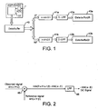
- Fig. 1 is a conceptual diagram illustrating digital quadrature detection underlying the concept of the present invention, and depicts subsequent processing on digital data obtained by the signal processing portion 32.
- Time domain data stored in a data buffer 40 are copied as two data sets. One data set is multiplied by sin ⁇ t, while the other is multiplied by cos ⁇ t.
- the products are passed through digital low-pass filters (D-LPFs) 42a and 42b, respectively, and stored in data buffers 2R and 2I, respectively.
- the stored data sets are taken as real and imaginary data, respectively.
- the data buffers 2R and 2I are indicated by 43a and 43b, respectively.
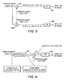
- Fig. 2 illustrates lock-in detection and the principle of a lock-in amplifier. It is assumed that an observed signal consists of a single frequency. The observed signal can be given by sin ( ⁇ t + ⁇ ) . A case is discussed in which a reference signal is prepared and brought into coincidence with the observed signal in terms of frequency or the frequency is swept for coincidence.
- the reference signal can be given by sin ( ⁇ t + ⁇ ). If the product of the reference signal sin ( ⁇ t + ⁇ ) and observed signal sin ( ⁇ t + ⁇ ) is calculated by a multiplier 45, formulas of products and sums of trigonometric functions state that the output from the multiplier 45 is given by cos 2 ⁇ ⁇ ⁇ t + ⁇ + ⁇ - cos ⁇ - ⁇ Of this formula, the former term is an AC component varying with time. The latter term is a DC component not varying with time.
- Quadrature lock-in detection is next described.
- the reference signal shown in Fig. 2 is sin ( ⁇ t + ⁇ ).
- the phase is not definite. The signal cannot be observed depending on the value of ⁇ and thus the phase of the observed signal cannot be known. (Usually, the phase is to be optimized.) To avoid this, a quadrature lock-in amplifier is available.
- Fig. 3 illustrates quadrature lock-in detection. Like components are indicated by like reference numerals in both Figs. 2 and 3 .
- an observed signal is multiplied by reference signals by means of multipliers 45 and 45a, respectively.
- the observed signal is split into two parts which are multiplied by reference signals which are 90° out of phase (e.g., sine wave and cosine wave, respectively).
- the products are passed through low-pass filters 46 and 46a, respectively, in the same way as in the above-described example. They are observed as two out of phase signals.
- the reference signal is sin ( ⁇ t + ⁇ )
- the DC output signal from the low-pass filter 46 is - cos ( ⁇ - ⁇ )
- the reference signal is cos ( ⁇ t + ⁇ )
- the DC output signal from the low-pass filter 46a is sin ( ⁇ - ⁇ ).
- signals can be received with at least one of the two channels without depending on the phases of the observed signal ⁇ and reference signal ⁇ . Furthermore, the phase of the observed signal relative to the reference signal can be known. Note that symbols and coefficient 1/2 are omitted in Figs. 2 and 3 .
- FIG. 4 illustrates digital lock-in detection.
- An analog observed signal sin ( ⁇ t + ⁇ ) is entered.
- An A/D converter 47 converts the observed signal into a sequence of digital numerical values varying with time.
- the converted observed signal is input to one input terminal of a multiplier 48.
- a digital reference signal sin ( ⁇ t + ⁇ ) is input to the other input terminal of the multiplier 48.
- the reference signal is multiplied by a sequence of numerical values corresponding to a sine wave.
- the obtained sequence of numerical values is passed through a digital low-pass filter 49.
- a sequence of digital numerical values - cos ( ⁇ - ⁇ ) corresponding to a DC signal can be obtained.
- a lock-in amplifier that has been digitized in this way can also be available.
- a digital quadrature lock-in amplifier can also be achieved by combination with the circuit shown in Fig. 3 .
- Patent reference 1 An apparatus of this kind is known as disclosed, for example, in Patent reference 1.
- real and imaginary part data are obtained by DPSD complex detection based on a 4-fold oversampling technique, and the difference in amplitude between the real and imaginary part data is reduced.
- a technique regarding improvement of a quadrature phase detection technique for performing quadrature phase detection of a signal from the receiver coil of a magnetic resonance imaging apparatus is known (see, for example, Patent reference 2).
- Patent reference 3 Another technique for reconstructing a magnetic resonance signal is also known as disclosed, for example, in Patent reference 3.
- the magnetic resonance signal is separated into two signals by detection using two reference waves having resonance frequencies that are 90° out of phase.
- the detected signals are Fourier transformed and corrected in the Fourier space, thus removing noise. Then, the signal is reconstructed.
- Patent reference 1 Japanese Patent Laid-Open No. H10-99293 (paragraphs 0008-0012; Figs. 1 and 2 )
- Patent reference 2 Japanese Patent Laid-Open No. H5-317285 (paragraphs 0016-0034; Figs. 1 and 3 ).
- Patent reference 3 Japanese Patent Laid-Open No. H4-357937 (paragraphs 0015-0022; Fig. 6 ).
- US 2005/0099182 discloses an NMR apparatus having an analog-to-digital converter, a quadrature detector and a storage device for preserving the voltage signal.
- US 2005/0093545 discloses a quadrature detector wherein unnecessary frequency components are not produced.
- JP04327835 discloses an NMR apparatus having a orthogonal detector to mix detection signals with a reference signal, thereby obtaining the low frequency component of the signal.
- Rev Sci lustrum 70 1511-1513, 1999 discloses a method of digital quadrature detection in accordance with the preamble of claim 1.
- the present invention has been made. It would be desirable to provide a method and apparatus for digital quadrature lock-in detection permitting high-sensitivity observation of signals in magnetic resonance spectroscopy.
- a first aspect of the present invention provides a method of receiving a magnetic resonance signal or electron spin resonance signal by a digital quadrature detection technique according to claim 1.
- a second aspect of the present invention provides an apparatus for receiving a magnetic resonance signal or electron spin resonance signal by a digital quadrature detection technique according to claim 4.
- magnetic resonance signals can be received at higher sensitivity than heretofore.
- FIG. 5 is a block diagram showing main portions of an apparatus which may be used for carrying out the present invention.
- An observed signal can be given by sin ( ⁇ t + ⁇ ).
- the observed signal enters an ADC 60, where the signal is converted into digital data.
- the digital data are passed as a sequence of digital numerical values into multipliers 61a and 61b.
- Reference signals cos ( ⁇ t + ⁇ ) and sin ( ⁇ t + ⁇ ) are applied to the multipliers 61a and 61b, respectively.
- the multipliers 61a and 61b split parts of the observed signals are multiplied by the reference signals cos ( ⁇ t + ⁇ ) and sin ( ⁇ t + ⁇ ), respectively.
- the output signals from the multipliers 61a and 61b are passed through digital low-pass filters (LPFs) 62a and62b, respectively, so thathigh-frequency components are removed.
- LPFs digital low-pass filters
- the output signals from the filters 62a and 62b are DC signals sin ( ⁇ - ⁇ ) and - cos ( ⁇ - ⁇ ), respectively.
- the output from the multiplier 61a is given by sin (2 ⁇ t + ⁇ + ⁇ ) + sin ( ⁇ - ⁇ ).
- the output from the multiplier 61b is given by cos (2 ⁇ t + ⁇ + ⁇ ) - cos ( ⁇ - ⁇ ) .
- the hardware configuration of an apparatus according to an embodiment of the present invention is similar to the configuration shown in Figs. 7 and 8 except that audio filters 18a, 18b, A/D converters 31a, 31b, signal processing portion 32, and other components cope with sampling at high frequencies above approximately 2 MHz.
- Digital data accepted by the signal processing portion 32 are computed as shown in Fig. 1 .
- the computation is performed serially every one NMR data set obtained by sampling.
- a high-speed board computer or digital signal processor (DSP) is required as the signal processing portion of relatively high computational speed.
- the signal processing portion is a device for processing data that the spectrometer receives. Serial detection NMR instrument can be implemented in this embodiment.
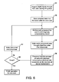
- Fig. 6 is a flowchart illustrating one example of sequence of operations of the apparatus according to the present invention.
- magnetic resonance signals can be received at higher sensitivity than heretofore.
- the hardware configuration of an apparatus according to the present embodiment of the invention is similar to the configuration shown in Figs. 7 and 8 except that audio filters 18a, 18b, A/D converters 31a, 31b, signal processing portion 32, and other components cope with sampling at high frequencies above approximately 2 MHz.
- Digital data accepted by the signal processing portion 32 are computed as shown in Fig. 1 .
- the computation is performed serially every one NMR data set obtained by sampling.
- a high-speed board computer or digital signal processor (DSP) is required as the signal processing portion of relatively high computational speed.
- the signal processing portion is a device for processing data that the spectrometer receives. Batch detectionNMR instrument canbe implemented in this embodiment. The sequence of operations of the instrument constructed in this way is described by referring to the flowchart of Fig. 6 .
- magnetic resonance signals can be received at higher sensitivity than heretofore.
Landscapes
- Physics & Mathematics (AREA)
- Condensed Matter Physics & Semiconductors (AREA)
- General Physics & Mathematics (AREA)
- Magnetic Resonance Imaging Apparatus (AREA)
Claims (4)
- Verfahren zur digitalen Quadratur-Lock-in-Detektion zum Empfangen eines Magnetresonanzsignals oder eines Elektronenspinresonanzsignals durch eine digitale Quadratur-Lock-in-Detektionstechnik,
wobei das Verfahren die Schritte umfasst:Digitalisieren eines beobachteten Magnetresonanzsignals oder Elektronenspinresonanzsignals;dadurch gekennzeichnet,a) Multiplizieren des digitalisierten Signals durch digitalisierte Referenzsignale von Sinus- und Kosinusfunktionen einer Frequenz Ω, um Signale von Real- und Imaginärteilen zu erhalten, welche 90° phasenverschoben sind;b) digitale Tiefpassfilterung der erhaltenen Signale durch ein Tiefpassfilter (42a, 42b);c) Erfassen der Intensität der digital tiefpassgefilterten Signale;
dass im Schritt b) das Tiefpassfilter (42a, 42b) eine Grenzfrequenz aufweist, welche angepasst ist, um gleich der oder kleiner als die digitale Auflösung zu sein, welche durch Dividieren der Spektralbreite SW des beobachteten Signals durch die Anzahl von Datenpunkten NP erhalten wird; und
dass das Verfahren ferner umfasst:Wiederholen der Schritte a), b) und c) NP-mal, wobei die Frequenz Ω der digitalisierten Referenzsignale von Sinus- und Kosinusfunktionen durch einen Betrag ΔΩ variiert wird, wobei NP x ΔΩ = SW, wodurch die Intensität des digitalisieren Signals von einem Ende zum anderen Ende der Spektralbreite SW erfasst wird. - Verfahren zur digitalen Quadratur-Lock-in-Detektion nach Anspruch 1, wobei der Schritt des Digitalisierens des beobachteten Magnetresonanzsignals oder Elektronenspinresonanzsignals unter Verwendung eines einzelnen Analog-zu-Digital-Wandlers (60) ausgeführt wird.
- Verfahren zur digitalen Quadratur-Lock-in-Detektion nach Anspruch 2, wobei das beobachtete Magnetresonanzsignal oder Elektronenspinresonanzsignal, welches durch den einzelnen Analog-zu-Digital-Wandler (60) digitalisiert wurde, in eine Signalwelle für einen Realteil und eine Signalwelle für einen Imaginärteil aufgeteilt wird, und danach diese Signalwellen jeweils mit den digitalisierten Referenzwellen von Sinus- und Kosinusfunktionen multipliziert werden.
- Vorrichtung zur digitalen Quadratur-Lock-in-Detektion,
welche dazu eingerichtet ist, ein Magnetresonanzsignal oder ein Elektronenspinresonanzsignal mittels einer digitalen Quadraturdetektionstechnik zu empfangen,
wobei die Vorrichtung Mittel zum Durchführen des in einem der Ansprüche 1 bis 3 definierten Verfahrens umfasst.
Applications Claiming Priority (1)
| Application Number | Priority Date | Filing Date | Title |
|---|---|---|---|
| JP2005186367A JP2007003458A (ja) | 2005-06-27 | 2005-06-27 | ディジタル直交ロックイン検出方法及び装置 |
Publications (2)
| Publication Number | Publication Date |
|---|---|
| EP1739445A1 EP1739445A1 (de) | 2007-01-03 |
| EP1739445B1 true EP1739445B1 (de) | 2010-12-29 |
Family
ID=36954253
Family Applications (1)
| Application Number | Title | Priority Date | Filing Date |
|---|---|---|---|
| EP06253112A Expired - Fee Related EP1739445B1 (de) | 2005-06-27 | 2006-06-15 | Kernresonanz unter Verwendung von digitaler Quadraturdetektion mit Referenzsignalen variierender Frequenz |
Country Status (4)
| Country | Link |
|---|---|
| US (1) | US7405568B2 (de) |
| EP (1) | EP1739445B1 (de) |
| JP (1) | JP2007003458A (de) |
| DE (1) | DE602006019173D1 (de) |
Families Citing this family (4)
| Publication number | Priority date | Publication date | Assignee | Title |
|---|---|---|---|---|
| DE102010041571B4 (de) * | 2010-09-28 | 2012-11-22 | Hauni Maschinenbau Ag | Vorrichtung und Verfahren zur Verarbeitung und Messung von Eigenschaften eines bewegten Materialstrangs |
| JP5890129B2 (ja) * | 2011-09-07 | 2016-03-22 | 株式会社 Jeol Resonance | パルスesr装置 |
| DE102014206311B3 (de) * | 2014-04-02 | 2015-10-08 | Siemens Aktiengesellschaft | Empfangssystem für Lokalspulen eines Magnetresonanztomographiesystems |
| JP6304761B2 (ja) * | 2014-07-23 | 2018-04-04 | 日本電子株式会社 | 磁気共鳴測定装置 |
Family Cites Families (17)
| Publication number | Priority date | Publication date | Assignee | Title |
|---|---|---|---|---|
| GB2176356A (en) * | 1985-06-12 | 1986-12-17 | Philips Electronic Associated | Method of, and demodulator for, digitally demodulating an ssb signal |
| JPS63302841A (ja) * | 1987-06-03 | 1988-12-09 | Fuji Electric Co Ltd | 核磁気共鳴映像装置の計測デ−タ誤差補償方法 |
| JPS648959A (en) * | 1987-06-30 | 1989-01-12 | Yokogawa Medical Syst | Nuclear magnetic resonance tomographic imaging apparatus |
| US4992736A (en) * | 1989-08-04 | 1991-02-12 | General Electric Company | Radio frequency receiver for a NMR instrument |
| US5170123A (en) * | 1989-08-11 | 1992-12-08 | Picker International, Inc. | Magnetic resonance imager with digital transmitter/receiver |
| JPH04327835A (ja) * | 1991-04-26 | 1992-11-17 | Hitachi Ltd | 磁気共鳴イメージング装置 |
| JPH0771552B2 (ja) * | 1991-05-17 | 1995-08-02 | 株式会社東芝 | 核磁気共鳴装置 |
| JPH05317285A (ja) | 1992-05-25 | 1993-12-03 | Hitachi Medical Corp | 磁気共鳴イメージング装置 |
| JP3274891B2 (ja) * | 1992-09-21 | 2002-04-15 | 株式会社日立メディコ | 核磁気共鳴検査装置 |
| JP3114955B2 (ja) * | 1993-08-05 | 2000-12-04 | 株式会社日立製作所 | 核磁気共鳴装置 |
| JP3478924B2 (ja) * | 1995-06-23 | 2003-12-15 | 日本電子株式会社 | 核磁気共鳴スペクトルの自動位相補正装置 |
| EP0774850B1 (de) * | 1995-11-16 | 2004-10-27 | Ntt Mobile Communications Network Inc. | Verfahren zum Erfassen eines digitalen Signals und Detektor |
| JPH1099293A (ja) | 1996-09-30 | 1998-04-21 | Shimadzu Corp | 核磁気共鳴検査装置 |
| JP2001108640A (ja) * | 1999-10-12 | 2001-04-20 | Agency Of Ind Science & Technol | Nmr装置 |
| EP1193506A3 (de) * | 2000-09-29 | 2004-07-21 | Siemens Aktiengesellschaft | Verfahren zum Abtasten eines hochfrequenten Empfangssignals, insbesondere eines Hochfrequenzsignals einer Empfangsspule eines Magnetresonanzgeräts |
| JP4076490B2 (ja) * | 2003-10-30 | 2008-04-16 | ジーイー・メディカル・システムズ・グローバル・テクノロジー・カンパニー・エルエルシー | 直交検波方法および装置並びにmri装置 |
| JP4021402B2 (ja) * | 2003-11-11 | 2007-12-12 | 株式会社日立製作所 | 制御可能な検波部を有する核磁気共鳴装置 |
-
2005
- 2005-06-27 JP JP2005186367A patent/JP2007003458A/ja active Pending
-
2006
- 2006-06-15 DE DE602006019173T patent/DE602006019173D1/de not_active Expired - Lifetime
- 2006-06-15 EP EP06253112A patent/EP1739445B1/de not_active Expired - Fee Related
- 2006-06-23 US US11/474,100 patent/US7405568B2/en not_active Expired - Fee Related
Also Published As
| Publication number | Publication date |
|---|---|
| EP1739445A1 (de) | 2007-01-03 |
| US7405568B2 (en) | 2008-07-29 |
| JP2007003458A (ja) | 2007-01-11 |
| DE602006019173D1 (de) | 2011-02-10 |
| US20070010733A1 (en) | 2007-01-11 |
Similar Documents
| Publication | Publication Date | Title |
|---|---|---|
| EP0412747B1 (de) | Magnetresonanzsysteme | |
| Michal et al. | A high performance digital receiver for home-built nuclear magnetic resonance spectrometers | |
| US6653833B2 (en) | Method for sampling a received radio-frequency signal, in particular a radio-frequency signal from a receiving coil in a magnetic resonance apparatus | |
| EP0104781B1 (de) | Gerät zur Verarbeitung von Empfangssignalen in einem mittels magnetischer Kernresonanz arbeitenden Diagnostikapparat | |
| US6633162B2 (en) | System and method for filtering frequency encoded imaging signals | |
| US4949040A (en) | Magnetic resonance spectrometer | |
| US7405568B2 (en) | Method and apparatus for digital quadrature lock-in detection in magnetic resonance | |
| JP3122144B2 (ja) | 計器の中間周波数応答特性を得る方法 | |
| US7747403B2 (en) | Method for measuring the phase jitter of a high-frequency signal and a measuring device for the implementation of this method | |
| US7504828B2 (en) | Frequency synthesizer for RF pulses, MRI apparatus and RF pulse generating method | |
| Kozioł et al. | Continuous wave electron paramagnetic resonance L-band spectrometer with direct digitalization using time-locked subsampling | |
| Pérez et al. | Potential use of the undersampling technique in the acquisition of nuclear magnetic resonance signals | |
| D. Traficante | Phase‐sensitive detection. Part II: quadrature phase detection | |
| JP2006017486A (ja) | 核磁気共鳴を用いるスペクトル分析方法および核磁気共鳴装置 | |
| US4873486A (en) | Magnetic resonance spectrometer | |
| CN108988967B (zh) | 防止由镜频导致的干扰的方法和系统 | |
| Kasal et al. | Signal processing in transceivers for nuclear magnetic resonance and imaging | |
| CN100565224C (zh) | 用于频谱分析仪的频率转换器中实际谱线和影像谱线区分 | |
| JP3111419B2 (ja) | 核磁気共鳴検査装置 | |
| JPH10126217A (ja) | デシメーションフィルタ | |
| US5652518A (en) | Digital filter pre-charging | |
| Hyde et al. | Digital detection by time-locked sampling in EPR | |
| Perez et al. | Applying undersampling to the nuclear magnetic resonance signal | |
| JPH09117424A (ja) | 核磁気共鳴検査装置 | |
| JPH1099293A (ja) | 核磁気共鳴検査装置 |
Legal Events
| Date | Code | Title | Description |
|---|---|---|---|
| PUAI | Public reference made under article 153(3) epc to a published international application that has entered the european phase |
Free format text: ORIGINAL CODE: 0009012 |
|
| AK | Designated contracting states |
Kind code of ref document: A1 Designated state(s): AT BE BG CH CY CZ DE DK EE ES FI FR GB GR HU IE IS IT LI LT LU LV MC NL PL PT RO SE SI SK TR |
|
| AX | Request for extension of the european patent |
Extension state: AL BA HR MK YU |
|
| 17P | Request for examination filed |
Effective date: 20070511 |
|
| 17Q | First examination report despatched |
Effective date: 20070619 |
|
| AKX | Designation fees paid |
Designated state(s): DE GB |
|
| GRAP | Despatch of communication of intention to grant a patent |
Free format text: ORIGINAL CODE: EPIDOSNIGR1 |
|
| GRAS | Grant fee paid |
Free format text: ORIGINAL CODE: EPIDOSNIGR3 |
|
| GRAA | (expected) grant |
Free format text: ORIGINAL CODE: 0009210 |
|
| AK | Designated contracting states |
Kind code of ref document: B1 Designated state(s): DE GB |
|
| REG | Reference to a national code |
Ref country code: GB Ref legal event code: FG4D |
|
| REF | Corresponds to: |
Ref document number: 602006019173 Country of ref document: DE Date of ref document: 20110210 Kind code of ref document: P |
|
| REG | Reference to a national code |
Ref country code: DE Ref legal event code: R096 Ref document number: 602006019173 Country of ref document: DE Effective date: 20110210 |
|
| PGFP | Annual fee paid to national office [announced via postgrant information from national office to epo] |
Ref country code: GB Payment date: 20110615 Year of fee payment: 6 |
|
| PGFP | Annual fee paid to national office [announced via postgrant information from national office to epo] |
Ref country code: DE Payment date: 20110608 Year of fee payment: 6 |
|
| PLBE | No opposition filed within time limit |
Free format text: ORIGINAL CODE: 0009261 |
|
| STAA | Information on the status of an ep patent application or granted ep patent |
Free format text: STATUS: NO OPPOSITION FILED WITHIN TIME LIMIT |
|
| 26N | No opposition filed |
Effective date: 20110930 |
|
| REG | Reference to a national code |
Ref country code: DE Ref legal event code: R097 Ref document number: 602006019173 Country of ref document: DE Effective date: 20110930 |
|
| GBPC | Gb: european patent ceased through non-payment of renewal fee |
Effective date: 20120615 |
|
| REG | Reference to a national code |
Ref country code: DE Ref legal event code: R119 Ref document number: 602006019173 Country of ref document: DE Effective date: 20130101 |
|
| PG25 | Lapsed in a contracting state [announced via postgrant information from national office to epo] |
Ref country code: DE Free format text: LAPSE BECAUSE OF NON-PAYMENT OF DUE FEES Effective date: 20130101 Ref country code: GB Free format text: LAPSE BECAUSE OF NON-PAYMENT OF DUE FEES Effective date: 20120615 |