EP1738968A1 - Gassack - Google Patents
Gassack Download PDFInfo
- Publication number
- EP1738968A1 EP1738968A1 EP06012726A EP06012726A EP1738968A1 EP 1738968 A1 EP1738968 A1 EP 1738968A1 EP 06012726 A EP06012726 A EP 06012726A EP 06012726 A EP06012726 A EP 06012726A EP 1738968 A1 EP1738968 A1 EP 1738968A1
- Authority
- EP
- European Patent Office
- Prior art keywords
- wall
- wall part
- section
- airbag
- gas bag
- Prior art date
- Legal status (The legal status is an assumption and is not a legal conclusion. Google has not performed a legal analysis and makes no representation as to the accuracy of the status listed.)
- Granted
Links
Images




Classifications
-
- B—PERFORMING OPERATIONS; TRANSPORTING
- B60—VEHICLES IN GENERAL
- B60R—VEHICLES, VEHICLE FITTINGS, OR VEHICLE PARTS, NOT OTHERWISE PROVIDED FOR
- B60R21/00—Arrangements or fittings on vehicles for protecting or preventing injuries to occupants or pedestrians in case of accidents or other traffic risks
- B60R21/02—Occupant safety arrangements or fittings, e.g. crash pads
- B60R21/16—Inflatable occupant restraints or confinements designed to inflate upon impact or impending impact, e.g. air bags
- B60R21/23—Inflatable members
- B60R21/231—Inflatable members characterised by their shape, construction or spatial configuration
-
- B—PERFORMING OPERATIONS; TRANSPORTING
- B60—VEHICLES IN GENERAL
- B60R—VEHICLES, VEHICLE FITTINGS, OR VEHICLE PARTS, NOT OTHERWISE PROVIDED FOR
- B60R21/00—Arrangements or fittings on vehicles for protecting or preventing injuries to occupants or pedestrians in case of accidents or other traffic risks
- B60R21/02—Occupant safety arrangements or fittings, e.g. crash pads
- B60R21/16—Inflatable occupant restraints or confinements designed to inflate upon impact or impending impact, e.g. air bags
- B60R21/23—Inflatable members
- B60R21/235—Inflatable members characterised by their material
- B60R2021/23533—Inflatable members characterised by their material characterised by the manufacturing process
- B60R2021/23538—Sewing
-
- B—PERFORMING OPERATIONS; TRANSPORTING
- B60—VEHICLES IN GENERAL
- B60R—VEHICLES, VEHICLE FITTINGS, OR VEHICLE PARTS, NOT OTHERWISE PROVIDED FOR
- B60R21/00—Arrangements or fittings on vehicles for protecting or preventing injuries to occupants or pedestrians in case of accidents or other traffic risks
- B60R21/02—Occupant safety arrangements or fittings, e.g. crash pads
- B60R21/16—Inflatable occupant restraints or confinements designed to inflate upon impact or impending impact, e.g. air bags
- B60R21/23—Inflatable members
- B60R21/239—Inflatable members characterised by their venting means
Definitions
- the invention relates to a gas bag.
- the object of the invention is to provide a gas bag, the wall parts can be sewn by means of flat seams and thus the wall parts can be sewn automatically.
- the invention provides an airbag, comprising a first wall part, a second wall part and a third wall part, wherein the first wall part has a first portion which is generally triangular, and an adjoining portion having a curved outer contour wherein the second wall portion has a first portion which is congruent with the first portion of the first wall portion, and an adjoining second portion which is a first portion a curved outer contour, wherein the third wall part has a first portion which is congruent with the second portion of the first wall part, and an adjoining second portion, which is congruent with the second portion of the second wall part.
- An airbag should have a pronounced three-dimensional shape in the unfolded state, so that on the one hand a vehicle occupant restrained faces as large a surface as possible, which provides a retention effect for the head, the upper body and possibly also for the knees or thighs, and on the other hand great depth is achieved, which allows a large retention path.
- Such a pronounced three-dimensional shape is achieved in the invention in that the first wall part réellerechtrecht from the dashboard, then the third wall part on the side facing the vehicle occupant forward and down and finally the second wall part extends back to the dashboard. Due to the possible variation of the curved sections of the wall parts, depending on the type of vehicle, the extension from the dashboard upwards or back to the dashboard can be varied.
- the third wall portion can be sewn to the first and second wall portions by means of a circumferential, planar seam around the third wall portion, whereby automated sewing is possible.
- the second portion of the first wall portion on rectilinear portions, wherein the first portion of the third wall portion has corresponding rectilinear portions. Due to the rectilinear areas of the gas bag waste is reduced.
- the second portion of the first wall portion may have a greater height than the second portion of the second wall portion.
- the second portions of the first and second wall portions have indentations, wherein the first and second portions of the third wall portion having corresponding notches, whereby a mutual alignment is possible, which prevents a false assembly.
- the first wall part and the second wall part are in particular made in one piece with each other, so that a two-part airbag is present, the has less items. Furthermore, the parts are asymmetrical in order to prevent misincorporation.
- the first and second wall part are sewn to the third wall part by means of a continuous seam.
- This seam can be manufactured automatically, which is inexpensive.
- the tip remote from the second portion of the first portion of the first and second wall portion is cut off, so that an opening is formed. It must therefore be subsequently cut no opening.
- the wall parts are made of polyamide, for example. This material is already used in gas bags because it has sufficient flexibility and can be used for any known folding method.
- heat protection is generally trapezoidal.
- the trapezoidal shape allows the heat protection can be turned funnel-shaped, so that it leans against the wall parts during inflation of the airbag and protects them from the heat of the outflowing gas.
- the heat protection on a recess so that an opening is formed. It must be cut no subsequent opening.
- Seams of the heat protection are preferably located outside of a blowing area.
- the seams, which are particularly susceptible to heat, are therefore not exposed to thermal stresses.
- the heat protection may be, for example, a coated fabric such as polypropylene.
- a coated fabric such as polypropylene.
- polyamide could be used, which has a high strength and temperature resistance.
- FIG. 1 shows an airbag 10, which consists of a first wall part 12, a second wall part 14 and a third wall part 16.
- the wall parts 12, 14, 16 are made of polypropylene.
- the gas bag 10 is shown here without an attached gas generator.
- an opening 18 (FIG. 2) is provided, through which a gas deflector 19 extends before attaching the gas generator.
- the gas deflection is placed together with the gas generator inside the airbag 10, so that the gas generator is surrounded by the gas deflection.
- an outlet opening 22 is provided, which allows an outflow of the gas.
- An external protective cover is designated 20, which is intended to prevent the ingress of dirt and moisture into a housing, not shown.
- first and second wall portion 12, 14 is shown, which are integral with each other.
- first wall part 12 and the second wall part 14 could each be in one piece and sewn together on a line F or otherwise connected.
- the wall parts 12, 14, 16 are notionally divided into sections.
- Both the first wall part 12 and the second wall part 14 have a generally triangular first portion 24, 26, which are formed congruent.
- the first wall part 12 has, subsequent to the first section 24, a second section 28 which is axisymmetric to a height H 1 and consists of two rectilinear regions 30 and a curved outer contour 32.
- the second wall portion 14 also has a second portion 34 which has a curved outer contour 36 and is axisymmetric to a height H 2 .
- the outlet opening 22 is disposed in the second wall portion 14, partially in the first portion 26 and partially in the second portion 34th
- a tip of the wall remote from the second section 28 of the first wall part 12 and a tip of the wall facing away from the second section 34 of the second wall part 14 are cut off, so that the opening 18 is formed.
- sections 38 are provided, which serve to receive and contacting a detonator, not shown.
- the seam shown has sewing reasons.
- the second wall portion 14 has no rectilinear portions and the curvature of the outer contour 36 is less than that of the first wall portion 12, the height H 2 of the second wall portion is less than the height H 1 of the first wall portion 12, thereby sewn on wall parts and inflated airbag 10 is an oblique impact surface for a vehicle occupant.
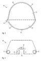
- FIG. 3 shows the third wall part 16, which has a first section 40 and a second section 42.
- the first portion 40 of the third wall portion 16 is congruent with the second portion 28 of the first wall portion 12, while the second portion 42 of the third wall portion 16 is congruent with the second portion 34 of the second wall portion 14.
- the second portion 42 of the third wall portion 16 has a tongue 44, which is helpful in sewing.
- Both the second portion 28 of the first wall portion 12, the second portion 34 of the second wall portion 14 and the first and second portions 40, 42 of the third wall portion 16 have notches 46, which are aligned with the notches 46 of the corresponding sections during sewing, so that a wrong installation is prevented.
- a heat shield 48 is shown, which is generally trapezoidal.
- the heat shield 48 is in one piece and a coated fabric, which here - as the wall parts 12, 14, 16 - is made of polypropylene.
- the heat shield 48 could be made of polyamide.
- the heat shield 48 has a generally rectangular recess 50 which forms the opening 18.
- the recess 50 or the opening 18 has - like the first and second wall part 12, 14 - the sections 38th
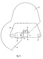
- FIG. 5 shows the first sewing step for producing the airbag 10.
- the integrally formed first and second wall portion 12, 14 is just laid out and the heat shield 48 and the protective cover 20 just laid on it.
- the heat shield 48 is sewn to the first wall portion 12.
- the seams at the portions 38 provide a further connection between the heat shield 48 and the first wall portion 12 and the protective cover 20, the heat shield 48 and the second wall portion 14 ago.
- the gas deflection 19, which directs a gas stream flowing out of the gas generator, is hereby cemented.
- FIG. 6 shows the second sewing step for producing the airbag 10.
- the second wall part 14 is first folded along the line F (FIG. 2) and placed on the first wall part 12 so that the lateral edges of the generally triangular, congruently formed first sections 24 , 26 of the first and second wall parts 12, 14 come to cover.
- the internal heat shield 48 is thereby folded, so that the outlet openings 22 of the heat shield 48 are aligned with the outlet opening 22 of the second wall part 14.
- the heat shield 48 is funnel-shaped after folding and has two fold lines.
- the outlet opening 22 formed by the heat shield 48 and the second wall part 14 is sewn. It is also the protective cover 20 with the heat shield 48 and the second wall part 14 sewn.
- FIG. 7 shows the third sewing step for producing the airbag 10.
- the third wall part is laid flat against the second wall part 14 such that the tongue 44 projects in the direction of the diffuser 20.
- On the tongue 44 of the third wall part of the sewing process is started, which can be done in one step and can be automated, since only a flat seam is necessary.
- the seam course is shown in FIG. 7 with arrows. The start is denoted by S, while the end of the seam is denoted by E.
- the notches 46 of the third wall portion 16 are aligned during sewing so that they lie on those of the first and second wall portion 12, 14.
- the third wall portion 16 is first flat with the second portion 34 of the second wall portion 14 and sewn flat.
- the third wall portion 16 can be sewn to the second portion 28 of the first wall portion 12 and then flat along the side of the generally triangular first sections 24, 26 of the first and second wall portion 12, 14 are sewn flat.
- the beginning of the seam is sewed, whereby at the beginning S of the seam is a double seam.
- the finished gas bag 10 is shown in FIG.
- the gas When activating a gas generator, the gas is deflected by the gas deflector 19.
- the funnel-shaped heat shield 48 leans against the first and second wall part 12, 14 when the gas flows in, thereby protecting the wall parts 12, 14, 16 from thermal stresses.
- the seam with which the heat shield 48 is connected to the first wall part 12, lies outside the outflow region of the gas generator, so that this seam is not thermally stressed.
Landscapes
- Engineering & Computer Science (AREA)
- Mechanical Engineering (AREA)
- Air Bags (AREA)
Abstract
Description
- Die Erfindung betrifft einen Gassack.
- Das Nähen eines Gassacks ist einer der arbeitsaufwendigsten und damit teuersten Herstellungsschritte bei der Fertigung eines Gassacks. Vor allem bei Gassäcken, die ihre dreidimensionale Gestalt im aufgeblasenen Zustand dadurch erhalten, daß ihre äußere Hülle nicht nur aus zwei flach aufeinandergenähten Wandungsteilen besteht, müssen oft Nähte geschlossen werden, für die sich die Wandungsteile nicht vollständig flach auf einem Tisch ausbreiten lassen. Diese Art der Verarbeitung ist umständlich und teuer, da die Wandungsteile nicht automatisiert vernäht werden können, sondern manuell vernäht werden müssen. Daher ist man bestrebt, Wandungsteile auch für dreidimensionale Gassäcke zu schaffen, bei denen alle Nahtvorgänge bei flach auf einer Unterlage liegenden Wandungsteilen mit sogenannten "zweidimensionalen Nähten" erfolgen können, also Nähten, die vollständig auf einer ebenen Unterlage genäht werden können.
- Die Aufgabe der Erfindung besteht darin, einen Gassack bereitzustellen, dessen Wandungsteile mittels ebener Nähte vernäht werden können und somit die Wandungsteile automatisiert vernäht werden können.
- Zu diesem Zweck sieht die Erfindung einen Gassack vor, bestehend aus einem ersten Wandungsteil, einem zweiten Wandungsteil und einem dritten Wandungsteil, wobei das erste Wandungsteil einen ersten Abschnitt aufweist, der allgemein dreieckig ist, sowie einen sich daran anschließenden Abschnitt, der eine gekrümmte Außenkontur aufweist, wobei das zweite Wandungsteil einen ersten Abschnitt aufweist, der mit dem ersten Abschnitt des ersten Wandungsteils kongruent ist, und einen sich daran anschließenden zweiten Abschnitt, der eine gekrümmte Außenkontur aufweist, wobei das dritte Wandungsteil einen ersten Abschnitt aufweist, der mit dem zweiten Abschnitt des ersten Wandungsteils kongruent ist, und einen sich daran anschließenden zweiten Abschnitt, der mit dem zweiten Abschnitt des zweiten Wandungsteils kongruent ist. Ein Gassack sollte im entfalteten Zustand eine ausgeprägt dreidimensionale Form haben, so daß zum einen einem zurückzuhaltenden Fahrzeuginsassen eine möglichst große Fläche zugewandt ist, die eine Rückhaltewirkung für den Kopf, den Oberkörper und möglichst auch für die Knie bzw. Oberschenkel bietet, und zum anderen eine große Tiefe erreicht wird, die einen großen Rückhalteweg ermöglicht. Eine solche ausgeprägt dreidimensionale Form wird bei der Erfindung dadurch erreicht, daß das erste Wandungsteil sich vom Armaturenbrett nach oben erstrecht, daran anschließend das dritte Wandungsteil auf der dem Fahrzeuginsassen zugewandten Seite nach vorne und unten und schließlich das zweite Wandungsteil zurück zum Armaturenbrett erstreckt. Aufgrund der möglichen Variation der gekrümmten Abschnitte der Wandungsteile kann je nach Fahrzeugtyp die Erstreckung vom Armaturenbrett nach oben bzw. zurück zum Armaturenbrett variiert werden. Da die gekrümmten Abschnitte des ersten und zweiten Wandungsteils kongruent mit den jeweiligen Abschnitten des dritten Wandungsteils sind, kann das dritte Wandungsteil an dem ersten und zweiten Wandungsteil mittels einer umlaufenden, ebenen Naht um das dritte Wandungsteil angenäht werden, wodurch ein automatisiertes Vernähen möglich ist.
- Vorzugsweise weist der zweite Abschnitt des ersten Wandungsteils geradlinige Bereiche auf, wobei der erste Abschnitt des dritten Wandungsteils dementsprechende geradlinige Bereiche aufweist. Aufgrund der geradlinigen Bereiche wird der Gassackverschnitt verringert.
- Der zweite Abschnitt des ersten Wandungsteils kann eine größere Höhe haben als der zweite Abschnitt des zweiten Wandungsteils. Dadurch wird eine variierbare, schräge Aufprallfläche für den Fahrzeuginsassen bereitgestellt.
- Gemäß einer Ausführungsform weisen die zweiten Abschnitte des ersten und zweiten Wandungsteils Einkerbungen auf, wobei der erste und zweite Abschnitt des dritten Wandungsteils dementsprechende Einkerbungen aufweist, wodurch ein gegenseitiges Ausrichten möglich ist, was einen Falschverbau verhindert.
- Das erste Wandungsteil und das zweite Wandungsteil sind insbesondere einstückig miteinander ausgeführt, so daß ein zweiteiliger Gassack vorliegt, der weniger Einzelteile hat. Ferner sind die Teile asymmetrisch, um einen Falschverbau zu verhindern.
- Vorzugsweise sind das erste und zweite Wandungsteil mit dem dritten Wandungsteil mittels einer durchgehenden Naht vernäht. Diese Naht kann automatisiert hergestellt werden, was kostengünstig ist.
- Vorzugsweise ist die vom zweiten Abschnitt abgewandte Spitze des ersten Abschnittes des ersten und des zweiten Wandungsteils abgeschnitten, so daß eine Öffnung gebildet ist. Es muß also nachträglich keine Öffnung ausgeschnitten werden.
- Die Wandungsteile sind zum Beispiel aus Polyamid. Dieses Material wird bereits in Gassäcken verwendet, da es eine ausreichende Flexibilität aufweist und für jede bekannte Faltmethode angewendet werden kann.
- Vorzugsweise ist ein Hitzeschutz allgemein trapezförmig ausgebildet. Die trapezförmige Form ermöglicht, daß der Hitzeschutz trichterförmig umgelegt werden kann, so daß er sich beim Aufblasen des Gassacks an die Wandungsteile anlehnt und diese vor der Hitze des ausströmenden Gases schützt.
- Gemäß einer Ausführungsform weist der Hitzeschutz eine Aussparung auf, so daß eine Öffnung gebildet ist. Es muß keine nachträgliche Öffnung ausgeschnitten werden.
- Nähte des Hitzeschutzes befinden sich bevorzugt außerhalb eines Einblasbereiches. Die Nähte, die besonders hitzeanfällig sind, sind somit keinen thermischen Belastungen ausgesetzt.
- Der Hitzeschutz kann zum Beispiel ein beschichtetes Gewebe wie Polypropylen sein. Genausogut könnte Polyamid verwendet werden, das eine hohe Festigkeit und Temperaturbeständigkeit hat.
- Weitere Merkmale und Vorteile ergeben sich aus den Unteransprüchen.
- Die Erfindung wird nachfolgend anhand der bevorzugten Ausführungsform beschrieben, die in den Zeichnungen dargestellt ist. In den Zeichnungen zeigen:
- Figur 1 eine Seitenansicht eines erfindungsgemäßen Gassacks,
- Figur 2 eine Ansicht eines ersten und zweiten Wandungsteils des Gassacks,
- Figur 3 eine Ansicht eines dritten Wandungsteils des Gassacks,
- Figur 4 eine Ansicht eines Hitzeschutzes des Gassacks,
- Figur 5 eine Ansicht eines ersten Nähschritts des Gassacks,
- Figur 6 eine Ansicht eines zweiten Nähschritts des Gassacks, und
- Figur 7 eine Ansicht eines dritten Nähschritts des Gassacks.
- In Figur 1 ist ein Gassack 10 gezeigt, der aus einem ersten Wandungsteil 12, einem zweiten Wandungsteil 14 und einem dritten Wandungsteil 16 besteht. Die Wandungsteile 12, 14, 16 sind aus Polypropylen. Der Gassack 10 ist hier ohne einen angebrachten Gasgenerator gezeigt.
- Am gemäß Figur 1 unteren Rand ist eine Öffnung 18 (Figur 2) vorgesehen, durch die sich vor dem Anbringen des Gasgenerators eine Gasumlenkung 19 erstreckt. Nach dem Einlegen des Gasgenerators wird die Gasumlenkung zusammen mit dem Gasgenerator ins Innere des Gassacks 10 gestülpt, so daß der Gasgenerator von der Gasumlenkung umgeben ist. Am zweiten Wandungsteil 14 ist eine Auslaßöffnung 22 vorgesehen, die ein Ausströmen des Gases zuläßt. Eine außenliegende Schutzabdeckung ist mit 20 bezeichnet, die ein Eindringen von Schmutz und Feuchtigkeit in ein nicht gezeigtes Gehäuse verhindern soll.
- In Figur 2 ist das erste und zweite Wandungsteil 12, 14 gezeigt, die einstückig miteinander ausgeführt sind. Genausogut könnte das erste Wandungsteil 12 und das zweite Wandungsteil 14 jeweils einteilig sein und an einer Linie F miteinander vernäht oder anderweitig verbunden werden.
- Zur Erleichterung der nachfolgenden Beschreibung sind die Wandungsteile 12, 14, 16 fiktiv in Abschnitte unterteilt.
- Sowohl das erste Wandungsteil 12 als auch das zweite Wandungsteil 14 weisen einen allgemein dreieckigen ersten Abschnitt 24, 26 auf, die kongruent ausgebildet sind. Das erste Wandungsteil 12 hat anschließend an den ersten Abschnitt 24 einen zweiten Abschnitt 28, der achsensymmetrisch zu einer Höhe H1 ist und aus zwei geradlinigen Bereichen 30 und einer gekrümmten Außenkontur 32 besteht.
- Das zweite Wandungsteil 14 hat ebenfalls einen zweiten Abschnitt 34, der eine gekrümmte Außenkontur 36 hat und achsensymmetrisch zu einer Höhe H2 ist.
- Die Auslaßöffnung 22 ist im zweiten Wandungsteil 14 angeordnet, und zwar teilweise im ersten Abschnitt 26 und teilweise im zweiten Abschnitt 34.
- Eine vom zweiten Abschnitt 28 des ersten Wandungsteils 12 abgewandte Spitze der Wandung und eine vom zweiten Abschnitt 34 des zweiten Wandungsteils 14 abgewandte Spitze der Wandung ist abgeschnitten, so daß die Öffnung 18 gebildet ist. Im Bereich der Öffnung 18 sind Abschnitte 38 vorgesehen, die der Aufnahme und Kontaktierung eines nicht gezeigten Zünders dienen. Der gezeigte Nahtverlauf hat nähtechnische Gründe.
- Da das zweite Wandungsteil 14 keine geradlinigen Bereiche aufweist und die Krümmung der Außenkontur 36 geringer ist als die des ersten Wandungsteils 12, ist die Höhe H2 des zweiten Wandungsteils geringer als die Höhe H1 des ersten Wandungsteils 12, wodurch bei vernähten Wandungsteilen und aufgeblasenen Gassack 10 eine schräge Aufprallfläche für einen Fahrzeuginsassen vorliegt.
- In Figur 3 ist das dritte Wandungsteil 16 gezeigt, das einen ersten Abschnitt 40 und einen zweiten Abschnitt 42 aufweist. Der erste Abschnitt 40 des dritten Wandungsteils 16 ist kongruent zum zweiten Abschnitt 28 des ersten Wandungsteils 12, während der zweite Abschnitt 42 des dritten Wandungsteils 16 kongruent mit dem zweiten Abschnitt 34 des zweiten Wandungsteils 14 ist. Zudem weist der zweite Abschnitt 42 des dritten Wandungsteils 16 eine Zunge 44 auf, die beim Vernähen hilfreich ist.
- Sowohl der zweite Abschnitt 28 des ersten Wandungsteils 12, der zweite Abschnitt 34 des zweiten Wandungsteils 14 und der erste und zweite Abschnitt 40, 42 des dritten Wandungsteils 16 weisen Einkerbungen 46 auf, die beim Vernähen mit den Einkerbungen 46 der entsprechenden Abschnitte ausgerichtet werden, so daß ein Falschverbau verhindert wird.
- In Figur 4 ist ein Hitzeschutz 48 gezeigt, der im allgemeinen trapezförmig ausgebildet ist. Der Hitzeschutz 48 ist einteilig und ein beschichtetes Gewebe, das hier ― wie die Wandungsteile 12, 14, 16 - aus Polypropylen ist. Genausogut könnte der Hitzeschutz 48 aus Polyamid sein.
- An der gemäß Figur 4 unteren Kante, die länger als die obere Kante ist, hat der Hitzeschutz 48 eine allgemein rechteckige Aussparung 50, die die Öffnung 18 bildet. Die Aussparung 50 bzw. die Öffnung 18 hat - wie das erste und zweite Wandungsteil 12, 14 - die Abschnitte 38.
- An den gemäß Figur 4 unteren Ecken sind zwei Auslaßöffnungen 22 vorgesehen, die nach dem Falten des Hitzeschutzes 48 zusammen mit dem ersten und zweiten Wandungsteil 12, 14 in einer Flucht mit der Auslaßöffnung 22 des zweiten Wandungsteils 14 liegen.
- In Figur 5 ist der erste Nähschritt zur Herstellung des Gassacks 10 gezeigt. Das einstückig ausgebildete erste und zweite Wandungsteil 12, 14 wird eben ausgebreitet und der Hitzeschutz 48 und die Schutzabdeckung 20 eben darauf gelegt. Mittels einer gemäß Figur 5 waagrechten Naht wird der Hitzeschutz 48 mit dem ersten Wandungsteil 12 vernäht. Die Nähte an den Abschnitten 38 stellen eine weitere Verbindung zwischen dem Hitzeschutz 48 und dem ersten Wandungsteil 12 bzw. der Schutzabdeckung 20, dem Hitzeschutz 48 und dem zweiten Wandungsteil 14 her. Die Gasumlenkung 19, die einen aus dem Gasgenerator ausströmenden Gasstrom lenkt, wird hierbei mitangenäht.
- Figur 6 zeigt den zweiten Nähschritt zur Herstellung des Gassacks 10. Das zweite Wandungsteil 14 wird zunächst entlang der Linie F (Figur 2) gefaltet und auf das erste Wandungsteil 12 gelegt, so daß die seitlichen Kanten der im allgemeinen dreieckigen, kongruent ausgebildeten ersten Abschnitte 24, 26 des ersten und zweiten Wandungsteils 12, 14 zur Deckung gelangen. Der innenliegende Hitzeschutz 48 wird dabei mitgefaltet, so daß die Auslaßöffnungen 22 des Hitzeschutzes 48 zur Auslaßöffnung 22 des zweiten Wandungsteils 14 fluchten. Der Hitzeschutz 48 ist nach dem Falten trichterförmig und hat zwei Faltlinien. Die vom Hitzeschutz 48 und dem zweiten Wandungsteil 14 gebildete Auslaßöffnung 22 wird vernäht. Es wird auch die Schutzabdeckung 20 mit dem Hitzeschutz 48 und dem zweiten Wandungsteil 14 vernäht.
- In Figur 7 ist der dritte Nähschritt zur Herstellung des Gassacks 10 gezeigt. Das dritte Wandungsteil wird so an dem zweiten Wandungsteil 14 flach angelegt, daß die Zunge 44 in Richtung des Diffusors 20 übersteht. An der Zunge 44 des dritten Wandungsteils wird der Nähvorgang begonnen, der in einem Schritt erfolgen kann und automatisiert werden kann, da nur eine ebene Naht notwendig ist. Der Nahtverlauf ist in Figur 7 mit Pfeilen dargestellt. Der Start ist mit einem S bezeichnet, während das Ende der Naht mit einem E bezeichnet ist.
- Die Einkerbungen 46 des dritten Wandungsteils 16 werden beim Vernähen so ausgerichtet, daß sie auf denen des ersten und zweiten Wandungsteils 12, 14 liegen. So wird das dritte Wandungsteil 16 zuerst mit dem zweiten Abschnitt 34 des zweiten Wandungsteils 14 flach aufeinanderliegend und eben vernäht. Nach einem Drehen der Wandungsteile kann das dritte Wandungsteil 16 mit dem zweiten Abschnitt 28 des ersten Wandungsteils 12 eben vernäht werden und daraufhin entlang der Seite der im allgemeinen dreieckigen ersten Abschnitte 24, 26 des ersten und zweiten Wandungsteils 12, 14 eben vernäht werden. Dabei wird der Anfang der Naht übernäht, wodurch am Anfang S der Naht eine doppelte Naht vorliegt.
- Der fertiggestellte Gassack 10 ist in Figur 1 gezeigt.
- Nach dem Anbringen des Gasgenerators und nachdem der Gasgenerator zusammen mit der Gasumlenkung in das Innere des Gassacks 10 umgestülpt ist, ist die Funktionsweise der Rückhalteeinrichtung folgendermaßen:
- Bei einem Aktivieren eines Gasgenerators wird das Gas durch die Gasumlenkung 19 umgelenkt. Der trichterförmige Hitzeschutz 48 lehnt sich an das erste und zweite Wandungsteil 12, 14 an, wenn das Gas einströmt und schützt dabei die Wandungsteile 12, 14, 16 vor thermischen Belastungen. Die Naht, mit der der Hitzeschutz 48 mit dem ersten Wandungsteil 12 verbunden ist, liegt außerhalb des Abströmbereichs des Gasgenerators, so daß diese Naht nicht thermisch belastet ist.
Claims (13)
- Gassack bestehend aus einem ersten Wandungsteil (12), einem zweiten Wandungsteil (14) und einem dritten Wandungsteil (16), wobei das erste Wandungsteil (12) einen ersten Abschnitt (24) aufweist, der allgemein dreieckig ist, sowie einen sich daran anschließenden Abschnitt (28), der eine gekrümmte Außenkontur (32) aufweist, wobei das zweite Wandungsteil (14) einen ersten Abschnitt (26) aufweist, der mit dem ersten Abschnitt (24) des ersten Wandungsteils (12) kongruent ist, und einen sich daran anschließenden zweiten Abschnitt (34), der eine gekrümmte Außenkontur (36) aufweist, wobei das dritte Wandungsteil (16) einen ersten Abschnitt (40) aufweist, der mit dem zweiten Abschnitt (28) des ersten Wandungsteils (12) kongruent ist, und einen sich daran anschließenden zweiten Abschnitt (42), der mit dem zweiten Abschnitt (34) des zweiten Wandungsteils (14) kongruent ist.
- Gassack nach Anspruch 1, dadurch gekennzeichnet, daß der zweite Abschnitt (28) des ersten Wandungsteils (12) geradlinige Bereiche (30) aufweist, wobei der erste Abschnitt (40) des dritten Wandungsteils (16) dementsprechende geradlinige Bereiche aufweist.
- Gassack nach Anspruch 1 oder 2, dadurch gekennzeichnet, daß der zweite Abschnitt (28) des ersten Wandungsteils (12) eine größere Höhe H hat als der zweite Abschnitt (34) des zweiten Wandungsteils (14).
- Gassack nach einem der vorhergehenden Ansprüchen, dadurch gekennzeichnet, daß die zweiten Abschnitte (28, 34) des ersten und zweiten Wandungsteils (12, 14) Einkerbungen (46) aufweisen, wobei der erste und zweite Abschnitt (40, 42) des dritten Wandungsteils (16) dementsprechende Einkerbungen (46) aufweist.
- Gassack nach einem der vorhergehenden Ansprüchen, dadurch gekennzeichnet, daß das erste Wandungsteil (12) und das zweite Wandungsteil (14) einstückig miteinander ausgeführt sind.
- Gassack nach einem der vorhergehenden Ansprüchen, dadurch gekennzeichnet, daß das erste und zweite Wandungsteil (12, 14) mit dem dritten Wandungsteil (16) mittels einer durchgehenden Naht vernäht sind.
- Gassack nach einem der vorhergehenden Ansprüchen, dadurch gekennzeichnet, daß die vom zweiten Abschnitt (28, 34) abgewandte Spitze des ersten Abschnittes (24, 26) des ersten und des zweiten Wandungsteils (12, 14) abgeschnitten ist, so daß eine Öffnung (18) gebildet ist.
- Gassack nach einem der vorhergehenden Ansprüchen, dadurch gekennzeichnet, daß die Wandungsteile (12, 14, 16) aus Polyamid sind.
- Gassack nach einem der vorhergehenden Ansprüchen, dadurch gekennzeichnet, daß der Gassack (10) einen einteiligen Hitzeschutz (48) hat.
- Gassack nach Anspruch 9, dadurch gekennzeichnet, daß der Hitzeschutz (48) allgemein trapezförmig ausgebildet ist.
- Gassack nach Anspruch 9 oder 10, dadurch gekennzeichnet, daß der Hitzeschutz (48) eine Aussparung (50) aufweist, so daß eine Öffnung (18) gebildet ist.
- Gassack nach Anspruch 11, dadurch gekennzeichnet, daß sich Nähte des Hitzeschutzes (48) außerhalb des direkten Gasstroms befinden.
- Gassack nach einem der Ansprüchen 9 bis 12, dadurch gekennzeichnet, daß der Hitzeschutz (48) ein beschichtetes Gewebe ist.
Applications Claiming Priority (1)
| Application Number | Priority Date | Filing Date | Title |
|---|---|---|---|
| DE200510030873 DE102005030873A1 (de) | 2005-07-01 | 2005-07-01 | Gassack |
Publications (2)
| Publication Number | Publication Date |
|---|---|
| EP1738968A1 true EP1738968A1 (de) | 2007-01-03 |
| EP1738968B1 EP1738968B1 (de) | 2009-04-22 |
Family
ID=36972698
Family Applications (1)
| Application Number | Title | Priority Date | Filing Date |
|---|---|---|---|
| EP20060012726 Not-in-force EP1738968B1 (de) | 2005-07-01 | 2006-06-21 | Gassack |
Country Status (4)
| Country | Link |
|---|---|
| EP (1) | EP1738968B1 (de) |
| JP (1) | JP4928174B2 (de) |
| DE (2) | DE102005030873A1 (de) |
| ES (1) | ES2324364T3 (de) |
Cited By (1)
| Publication number | Priority date | Publication date | Assignee | Title |
|---|---|---|---|---|
| WO2013020642A1 (de) * | 2011-08-05 | 2013-02-14 | Trw Automotive Gmbh | Verfahren zur herstellung eines dreidimensionalen gassacks und dreidimensionaler gassack für eine fahrzeuginsassen-rückhaltevorrichtung |
Citations (3)
| Publication number | Priority date | Publication date | Assignee | Title |
|---|---|---|---|---|
| EP1024060A1 (de) | 1999-01-28 | 2000-08-02 | Breed Automotive Technology, Inc. | Verfahren zur Herstellung eines Airbags und Airbag |
| US20010040368A1 (en) | 1999-12-07 | 2001-11-15 | Yasushi Okada | Three-dimensional air bags for vehicles |
| US20030201631A1 (en) | 2002-04-30 | 2003-10-30 | Trw Occupant Restraint Systems Gmbh & Co. Kg | Gas bag for a vehicle occupant restraint system |
Family Cites Families (4)
| Publication number | Priority date | Publication date | Assignee | Title |
|---|---|---|---|---|
| ES2104345T3 (es) * | 1993-02-02 | 1997-10-01 | Johann Berger | Airbag y procedimiento para su fabricacion. |
| US5405166A (en) * | 1993-07-30 | 1995-04-11 | Alliedsignal Inc. | Air bag with inflation limiter |
| JP3443902B2 (ja) * | 1993-10-27 | 2003-09-08 | 豊田合成株式会社 | エアバッグ用布及び該布を用いたエアバッグの製造方法 |
| EP0966352B1 (de) * | 1997-03-14 | 2002-08-28 | E.I. Dupont de Nemours and Company, Inc. | Verbundschichtmaterial aus einem polyamidfilm und einem gewebe |
-
2005
- 2005-07-01 DE DE200510030873 patent/DE102005030873A1/de not_active Ceased
-
2006
- 2006-06-21 EP EP20060012726 patent/EP1738968B1/de not_active Not-in-force
- 2006-06-21 ES ES06012726T patent/ES2324364T3/es active Active
- 2006-06-21 DE DE200650003516 patent/DE502006003516D1/de active Active
- 2006-06-26 JP JP2006174775A patent/JP4928174B2/ja active Active
Patent Citations (3)
| Publication number | Priority date | Publication date | Assignee | Title |
|---|---|---|---|---|
| EP1024060A1 (de) | 1999-01-28 | 2000-08-02 | Breed Automotive Technology, Inc. | Verfahren zur Herstellung eines Airbags und Airbag |
| US20010040368A1 (en) | 1999-12-07 | 2001-11-15 | Yasushi Okada | Three-dimensional air bags for vehicles |
| US20030201631A1 (en) | 2002-04-30 | 2003-10-30 | Trw Occupant Restraint Systems Gmbh & Co. Kg | Gas bag for a vehicle occupant restraint system |
Cited By (1)
| Publication number | Priority date | Publication date | Assignee | Title |
|---|---|---|---|---|
| WO2013020642A1 (de) * | 2011-08-05 | 2013-02-14 | Trw Automotive Gmbh | Verfahren zur herstellung eines dreidimensionalen gassacks und dreidimensionaler gassack für eine fahrzeuginsassen-rückhaltevorrichtung |
Also Published As
| Publication number | Publication date |
|---|---|
| DE502006003516D1 (de) | 2009-06-04 |
| EP1738968B1 (de) | 2009-04-22 |
| ES2324364T3 (es) | 2009-08-05 |
| JP4928174B2 (ja) | 2012-05-09 |
| DE102005030873A1 (de) | 2007-01-04 |
| JP2007008457A (ja) | 2007-01-18 |
Similar Documents
| Publication | Publication Date | Title |
|---|---|---|
| EP2535229B1 (de) | Gassackanordnung für ein Fahrzeuginsassen-Rückhaltesystem | |
| DE102007056137B4 (de) | Gassack mit einem Einfüllstutzen und Gassackanordnung mit einem Gassack und einem Gasgenerator | |
| EP0995642A2 (de) | Gassack für ein Fahrzeuginsassen- Rückhaltesystem | |
| DE19946413A1 (de) | Gassack für ein Fahrzeuginsassen-Rückhaltesystem | |
| DE19858690A1 (de) | Luftsack | |
| DE10060667A1 (de) | Dreidimensionale Airbags für Kraftfahrzeuge | |
| DE102007016038A1 (de) | Airbag mit Gasdiffusor | |
| EP3107767B1 (de) | Seitenairbag für fahrzeuge | |
| WO2016070976A1 (de) | Frontgassack | |
| DE10122838A1 (de) | Luftsack für ein Curtain-Airbag Modul sowie ein entsprechendes Curtain-Airbag-Modul und ein Verfahren zur Herstellung des Luftsacks | |
| EP1062126B1 (de) | Airbagmodul, insbesondere beifahrerairbagmodul | |
| DE69910125T2 (de) | Aufblasbarer Sicherheitsgurt für Kraftfahrzeuge | |
| DE69900715T2 (de) | Verfahren zur Herstellung eines Airbags und Airbag | |
| DE102020134796B4 (de) | Airbagkissen für ein Fahrzeug | |
| DE60308840T2 (de) | Airbag | |
| DE102004006317B4 (de) | Gassack und Gssackmodul | |
| EP1738968B1 (de) | Gassack | |
| EP1922232B1 (de) | Gassack, insbesondere zum schutz des kniebereichs eines fahrzeuginsassen | |
| DE10355487B4 (de) | Gassack für ein Fahrzeuginsassen-Rückhaltesystem | |
| EP0992403A2 (de) | Gewebeteil zur Anordnung im Inneren eines Gassacks eines Fahrzeuginsassen-Rückhaltesystems | |
| EP1359060B1 (de) | Gassack für ein Fahrzeuginsassen-Rückhaltesystem | |
| EP0820904B1 (de) | Verfahren zur Herstellung eines Gassacks für ein Fahrzeuginsassen-Rückhaltesystem sowie Gassack | |
| DE10065461C2 (de) | Beifahrerairbagmodul | |
| EP1757493A1 (de) | Gassack für ein Fahrzeuginsassen- Rückhaltesystem | |
| WO2019215092A1 (de) | Vorhang-seitengassack |
Legal Events
| Date | Code | Title | Description |
|---|---|---|---|
| PUAI | Public reference made under article 153(3) epc to a published international application that has entered the european phase |
Free format text: ORIGINAL CODE: 0009012 |
|
| AK | Designated contracting states |
Kind code of ref document: A1 Designated state(s): AT BE BG CH CY CZ DE DK EE ES FI FR GB GR HU IE IS IT LI LT LU LV MC NL PL PT RO SE SI SK TR |
|
| AX | Request for extension of the european patent |
Extension state: AL BA HR MK YU |
|
| 17P | Request for examination filed |
Effective date: 20070511 |
|
| AKX | Designation fees paid |
Designated state(s): DE ES FR IT |
|
| 17Q | First examination report despatched |
Effective date: 20070813 |
|
| GRAP | Despatch of communication of intention to grant a patent |
Free format text: ORIGINAL CODE: EPIDOSNIGR1 |
|
| GRAS | Grant fee paid |
Free format text: ORIGINAL CODE: EPIDOSNIGR3 |
|
| GRAA | (expected) grant |
Free format text: ORIGINAL CODE: 0009210 |
|
| AK | Designated contracting states |
Kind code of ref document: B1 Designated state(s): DE ES FR IT |
|
| REF | Corresponds to: |
Ref document number: 502006003516 Country of ref document: DE Date of ref document: 20090604 Kind code of ref document: P |
|
| REG | Reference to a national code |
Ref country code: DE Ref legal event code: R096 Ref document number: 502006003516 Country of ref document: DE Effective date: 20090604 |
|
| REG | Reference to a national code |
Ref country code: ES Ref legal event code: FG2A Ref document number: 2324364 Country of ref document: ES Kind code of ref document: T3 |
|
| PLBE | No opposition filed within time limit |
Free format text: ORIGINAL CODE: 0009261 |
|
| STAA | Information on the status of an ep patent application or granted ep patent |
Free format text: STATUS: NO OPPOSITION FILED WITHIN TIME LIMIT |
|
| 26N | No opposition filed |
Effective date: 20100125 |
|
| REG | Reference to a national code |
Ref country code: DE Ref legal event code: R097 Ref document number: 502006003516 Country of ref document: DE Effective date: 20100125 |
|
| PGFP | Annual fee paid to national office [announced via postgrant information from national office to epo] |
Ref country code: ES Payment date: 20110628 Year of fee payment: 6 |
|
| REG | Reference to a national code |
Ref country code: ES Ref legal event code: FD2A Effective date: 20131023 |
|
| PG25 | Lapsed in a contracting state [announced via postgrant information from national office to epo] |
Ref country code: ES Free format text: LAPSE BECAUSE OF NON-PAYMENT OF DUE FEES Effective date: 20120622 |
|
| REG | Reference to a national code |
Ref country code: FR Ref legal event code: PLFP Year of fee payment: 11 |
|
| REG | Reference to a national code |
Ref country code: FR Ref legal event code: PLFP Year of fee payment: 12 |
|
| REG | Reference to a national code |
Ref country code: FR Ref legal event code: PLFP Year of fee payment: 13 |
|
| REG | Reference to a national code |
Ref country code: DE Ref legal event code: R081 Ref document number: 502006003516 Country of ref document: DE Owner name: ZF AUTOMOTIVE GERMANY GMBH, DE Free format text: FORMER OWNER: TRW AUTOMOTIVE GMBH, 73553 ALFDORF, DE Ref country code: DE Ref legal event code: R082 Ref document number: 502006003516 Country of ref document: DE Representative=s name: PRINZ & PARTNER MBB PATENTANWAELTE RECHTSANWAE, DE |
|
| P01 | Opt-out of the competence of the unified patent court (upc) registered |
Effective date: 20230628 |
|
| PGFP | Annual fee paid to national office [announced via postgrant information from national office to epo] |
Ref country code: DE Payment date: 20240630 Year of fee payment: 19 |
|
| PGFP | Annual fee paid to national office [announced via postgrant information from national office to epo] |
Ref country code: IT Payment date: 20240513 Year of fee payment: 19 Ref country code: FR Payment date: 20240408 Year of fee payment: 19 |
|
| REG | Reference to a national code |
Ref country code: DE Ref legal event code: R119 Ref document number: 502006003516 Country of ref document: DE |
|
| PG25 | Lapsed in a contracting state [announced via postgrant information from national office to epo] |
Ref country code: DE Free format text: LAPSE BECAUSE OF NON-PAYMENT OF DUE FEES Effective date: 20260101 |
|
| PG25 | Lapsed in a contracting state [announced via postgrant information from national office to epo] |
Ref country code: IT Free format text: LAPSE BECAUSE OF NON-PAYMENT OF DUE FEES Effective date: 20250621 |
|
| PG25 | Lapsed in a contracting state [announced via postgrant information from national office to epo] |
Ref country code: FR Free format text: LAPSE BECAUSE OF NON-PAYMENT OF DUE FEES Effective date: 20250630 |