EP1738141B1 - Flow meter for use with high pressure process fluid - Google Patents
Flow meter for use with high pressure process fluid Download PDFInfo
- Publication number
- EP1738141B1 EP1738141B1 EP05733073.0A EP05733073A EP1738141B1 EP 1738141 B1 EP1738141 B1 EP 1738141B1 EP 05733073 A EP05733073 A EP 05733073A EP 1738141 B1 EP1738141 B1 EP 1738141B1
- Authority
- EP
- European Patent Office
- Prior art keywords
- flow meter
- vortex flow
- reinforcing rib
- region
- reduced thickness
- Prior art date
- Legal status (The legal status is an assumption and is not a legal conclusion. Google has not performed a legal analysis and makes no representation as to the accuracy of the status listed.)
- Ceased
Links
- 239000012530 fluid Substances 0.000 title claims description 23
- 238000000034 method Methods 0.000 title description 5
- 230000008569 process Effects 0.000 title description 3
- 230000003014 reinforcing effect Effects 0.000 claims description 60
- 230000033001 locomotion Effects 0.000 claims description 14
- 230000004044 response Effects 0.000 claims description 5
- 230000001953 sensory effect Effects 0.000 claims 1
- 238000012360 testing method Methods 0.000 description 9
- 230000035945 sensitivity Effects 0.000 description 6
- 239000000463 material Substances 0.000 description 5
- 238000004364 calculation method Methods 0.000 description 4
- 238000013461 design Methods 0.000 description 4
- 238000005266 casting Methods 0.000 description 3
- 238000011144 upstream manufacturing Methods 0.000 description 3
- 239000007788 liquid Substances 0.000 description 2
- 230000014759 maintenance of location Effects 0.000 description 2
- 238000004458 analytical method Methods 0.000 description 1
- 230000005540 biological transmission Effects 0.000 description 1
- 230000008859 change Effects 0.000 description 1
- 238000006073 displacement reaction Methods 0.000 description 1
- 230000006872 improvement Effects 0.000 description 1
- 238000011065 in-situ storage Methods 0.000 description 1
- 238000004519 manufacturing process Methods 0.000 description 1
- 238000005259 measurement Methods 0.000 description 1
- 238000012986 modification Methods 0.000 description 1
- 230000004048 modification Effects 0.000 description 1
- 238000012545 processing Methods 0.000 description 1
Images

Classifications
-
- G—PHYSICS
- G01—MEASURING; TESTING
- G01F—MEASURING VOLUME, VOLUME FLOW, MASS FLOW OR LIQUID LEVEL; METERING BY VOLUME
- G01F1/00—Measuring the volume flow or mass flow of fluid or fluent solid material wherein the fluid passes through a meter in a continuous flow
- G01F1/05—Measuring the volume flow or mass flow of fluid or fluent solid material wherein the fluid passes through a meter in a continuous flow by using mechanical effects
- G01F1/20—Measuring the volume flow or mass flow of fluid or fluent solid material wherein the fluid passes through a meter in a continuous flow by using mechanical effects by detection of dynamic effects of the flow
- G01F1/32—Measuring the volume flow or mass flow of fluid or fluent solid material wherein the fluid passes through a meter in a continuous flow by using mechanical effects by detection of dynamic effects of the flow using swirl flowmeters
- G01F1/3209—Measuring the volume flow or mass flow of fluid or fluent solid material wherein the fluid passes through a meter in a continuous flow by using mechanical effects by detection of dynamic effects of the flow using swirl flowmeters using Karman vortices
- G01F1/3218—Measuring the volume flow or mass flow of fluid or fluent solid material wherein the fluid passes through a meter in a continuous flow by using mechanical effects by detection of dynamic effects of the flow using swirl flowmeters using Karman vortices bluff body design
-
- G—PHYSICS
- G01—MEASURING; TESTING
- G01F—MEASURING VOLUME, VOLUME FLOW, MASS FLOW OR LIQUID LEVEL; METERING BY VOLUME
- G01F1/00—Measuring the volume flow or mass flow of fluid or fluent solid material wherein the fluid passes through a meter in a continuous flow
- G01F1/05—Measuring the volume flow or mass flow of fluid or fluent solid material wherein the fluid passes through a meter in a continuous flow by using mechanical effects
- G01F1/20—Measuring the volume flow or mass flow of fluid or fluent solid material wherein the fluid passes through a meter in a continuous flow by using mechanical effects by detection of dynamic effects of the flow
- G01F1/32—Measuring the volume flow or mass flow of fluid or fluent solid material wherein the fluid passes through a meter in a continuous flow by using mechanical effects by detection of dynamic effects of the flow using swirl flowmeters
- G01F1/325—Means for detecting quantities used as proxy variables for swirl
- G01F1/3259—Means for detecting quantities used as proxy variables for swirl for detecting fluid pressure oscillations
- G01F1/3266—Means for detecting quantities used as proxy variables for swirl for detecting fluid pressure oscillations by sensing mechanical vibrations
Definitions
- the present invention relates to a vortex flow meter for measuring fluid flow, and more particularly, a flow meter for use with high pressure process fluid.
- Vortex flow meters are known in the prior art, and examples of vortex flow meter implementations can be found in U.S. Patent No. 4,926,695 issued to Kleven et al. on May 2, 1990 , U.S. Patent No. 5,343,762 issued to Beulke on September 6, 1994 , which are incorporated herein by reference.
- a vortex flow meter for measuring fluid flow includes a conduit having a wall surrounding a bore for carrying the fluid.
- the wall has a wall region of reduced thickness formed therein.
- the wall region of reduced thickness is sometimes referred to as a "region of reduced stiffness" or a "flexure”.
- a shedding bar is disposed in the bore.
- the shedding bar includes an upstream extremity, a downstream extremity and an intermediate portion connecting the upstream and downstream extremities.
- the intermediate portion includes a region of reduced stiffness which flexes in response to disturbances or vortices within the fluid created by fluid flow around the upstream extremity to promote motion of at least a portion of the downstream extremity.
- Such flow meters further include sensing means coupled to the downstream extremity for sensing the motion and providing an output as a function thereof.
- the sensing means senses lateral motion, and is removably attached to a post extending from the wall region away from the bore, wherein the post transmits the motion to the sensing means.
- the flexure For higher pressures, the flexure often presents a weak point in the structure, which can tear or burst open when exposed to higher pressures. Since the flexure must be designed to be thin enough to permit movement of the post that is coupled to the buff body or shedding bar, conventional flexures have difficulting providing the required safety factor at high pressures.
- a vortex flow meter for measuring fluid flow has a conduit for carrying a fluid.
- a region of reduced thickness is formed in a portion of the conduit.
- a shedder bar disposed in the conduit is coupled to the region of reduced thickness and is configured to apply a rocking motion to the region of reduced thickness about a pivot line in response to flow of the fluid.
- At least one reinforcing rib spaced from the pivot line on the reduced thickness portion extends parallel to flow of the fluid.
- burst > safety factor ⁇ PR FxR where PR is the maximum operating pressure for a pressure rating, F is a casting quality factor, and R is the ratio of actual to minimum tensile strength of the material utilized in the particular implementation.
- the safety factor may depend on the specific usage and the implementation.
- the present invention includes a modification to conventional flexures (sometimes referred to as regions of reduced wall thickness) to include a rib to extend across the flexure in the direction of flow on either side of the center line of the flexure. Additionally, the size of a center rib disposed on the center line of the flexure is increased. With these enhancements, the flexure is able to retain (withstand) a pressure that is approximately 150% that of a conventional meter. Additionally, the side ribs increase the sensitivity of the meter to alternating pressure created by the shedding bar, by reducing the countervailing force on the sensor due to pressure on the rigid center flexure of the meter.
- FIG. 1 illustrates an embodiment of a vortex flow meter of the present invention.
- Flowmeter 10 includes a conduit 12 having a wall 14 surrounding a bore 16. Bore 16 carries a fluid, which may be a liquid or a gas, generally along a bore axis 18.
- Shedding bar 20 is a vortex-generating obstruction.
- Pivoting member 22 extends from a hole 24 formed in wall 14 into bore 16. Fluctuating fluid pressures act on the shedding bar and on pivoting member 22, such that pivoting member 22 moves in response to the fluctuating pressures.
- a center rib 26 is disposed in hole 24 and coupled to flexure 28.
- the flexure 28 is generally coupled to wall 14.
- Post 30 extends from the flexure 28.
- a sensing device 32 (shown in phantom) is coupled to the flexure 28, preferably by attachment to the post 30, and senses the motion of pivoting member 22. The sensing device 32 generates an output indicative of the sensed motion and communicates the output via lead 34 to circuitry 36.
- circuitry 36 is adapted to communicate the sensed motion to a control center 38 via a communications link 40 (which may be a two-wire, three-wire or four-wire loop, or which may be a wireless communications link 40).
- reinforcing ribs 42 are disposed on the flexure on either side of centerline 27 (or pivot line) of the flexure 28 (reference numeral 27 is shown in FIGS. 2 and 5 ).
- centerline 27 or pivot line
- the center rib 26 and the reinforcing ribs 42 extend parallel to the direction to the bore axis 18 (parallel to the direction of flow).
- the reinforcing ribs 42 are positioned on the flexure between a center of the center rib 26 and the outside edge of the flexure 28.
- the position may be quantified by considering a flexure 28 of diameter D, where the reinforcing ribs 42 are positioned at approximately 0.25D on either side of the center rib 26.
- the reinforcing ribs 42 are centered between the edge of the center rib 26 and the outside edge of the flexure 28 (at approximately 0.22D, for example, relative to the edge of the flexure 28).
- the center rib 26 is approximately the same width as the post 30 and extends the entire diameter of the flexure 28.
- the center rib 26 is a fraction of an inch wider than the post 30 and extends the full diameter of the flexure.
- the reinforcing ribs are approximately the same relative height and width. In one embodiment, the reinforcing ribs have a height and a width that are approximately the same as the thickness of the flexure. It will be understood by a worker skilled in the art that the flexure 28 is curved so as to match the wall of the pipe. Thus, the height of the reinforcing ribs 42 is relative to the surface of the flexure 28, but varies relative to a fixed point according to a radius of curvature of the pipe.
- the rib size may be adjusted to account for different pressures and different flexure sizes. Additionally, the location of the reinforcing ribs 42 may be adjusted toward or away from the center line. In a preferred embodiment, the reinforcing ribs 42 are substantially centered between the center line of the flexure 28 and the outer edge of the flexure 28.
- reinforcing ribs 42 add to the burst pressure strength of the meter. Adding the reinforcing ribs 42 to a meter typically increases the burst pressure of the meter by 50%. Additionally, the reinforcing ribs 42 increase the sensitivity of the flow meter to the alternating pressure from the fluidic vortices, by reducing the countervailing force on the sensor due to pressure on the flexure 28 of the meter 10.
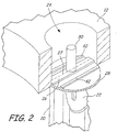
- FIG. 2 shows an expanded view of the flexure 28 of FIG. 1 .
- the conduit 12 has an opening 24 in which a flexure 28 is disposed.
- Center rib 26 extends a full diameter of the flexure, and is positioned on a center line 27 of the flexure 28.
- reinforcing ribs 42 are disposed on either side of the center rib 26 and extend to the outer edge of the flexure 28.
- the reinforcing ribs 42 are positioned at approximately a midpoint between the center line 27 and the outer edge of the flexure 28.
- Post 30 extends from the center rib 26 and away from the conduit 12.
- the sensor is coupled to the shedding bar via the post 30.
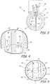
- FIG. 3 shows a cross sectional view of the vortex flow meter 10 of FIG. 1 taken along line 3-3.
- Flowmeter 10 includes a conduit 12 having a wall 14 surrounding a bore 16.
- Bore 16 carries a fluid, which may be a liquid or a gas, generally along a bore axis 18.
- Shedding bar 20 is a vortex-generating obstruction.
- Pivoting member 22 (shown in FIG. 1 ) extends from the wetted side of the flexure 28. Fluctuating fluid pressures act on the shedding bar and on pivoting member 22, such that pivoting member 22 moves in response to the fluctuating pressures.
- center rib 26 is disposed in hole 24 and coupled to flexure 28.
- the flexure 28 is generally coupled to wall 14.
- Post 30 extends from the flexure 28.
- Reinforcing ribs 42 are disposed on the flexure on either side of the center rib 26 on either side of a centerline of the flexure 28.
- the center rib 26 and the reinforcing ribs 42 extend parallel to the direction to the bore axis 18 (parallel to the direction of flow).
- Flange element 46 couples a transmitter housing 48 (shown in phantom) to the meter body.
- the transmitter housing 48 may also contain circuitry for processing sensed data into a signal for transmission to a control center.
- FIG. 4 illustrates an expanded cross-sectional view of the flexure 28.
- Flexure 28 is disposed in opening 24 within conduit 12.
- Center rib 26 is centered on the flexure 28, and reinforcing ribs 42 are approximately centered between the center rib 42 and the outer circumferential edge of the flexure 28.
- the center rib 26 and the reinforcing ribs 42 extend in parallel to each other and to the direction of fluid flow.
- Pivoting member 22 is disposed on shedding bar 20 and is coupled to the post 30 to cause the post 30 to move responsive to fluidic pressures experienced by the pivoting member 22 and the shedding bar 20.
- the flexure 28 (region of reduced thickness) has a thickness T.
- the reinforcing ribs 42 have a width W and a height H. It should be understood that the flexure 28 is curved to match the curvature of the pipe wall, such that the height H of the reinforcing ribs 42 is relative to the curved surface of the flexure 28. In a preferred embodiment, the width W and the height H are approximately equal to the thickness T.
- FIG. 5 shows the flexure 28 from a top view looking into opening 24.
- the flexure 28 has a diameter D, which can be measured from edge to edge along the outer (non-wetted) surface of the flexure 28.
- the position of the reinforcing ribs 42 may be determined relative to the centerline (pivot line) 27 of the flexure 28, such that the reinforcing ribs 42 are centered at approximately 0.25D.
- the primary method of determining the pressure rating for a meter is a burst pressure test.
- the flow meter is connected to a testing device and then pressurized until the meter fails because it can no longer retain the pressure.
- failures occurred in the flexure area, which is the thinnest wall section.
- SF the safety factor
- F is a casting quality factor
- BP burst pressure
- P r rated pressure
- T s is the material's tensile strength specification
- T a is actual tensile strength of the material tested as determined by a test specimen from the heat the casting is taken from.
- the reinforcing ribs were approximately 0.035 inches wide and 0.070 inches tall and extended parallel to the center rib 26.
- the reinforcing ribs 42 were positioned at the area where the maximum total displacement occurred in the prior art design. Calculations predicted a greater than 30 percent increase in burst pressure. The tested device showed improvement in burst pressure of 50 percent.
- center rib contributes to a restorative force tending to restore pivoting member 22 to its equilibrium position.
- the restoring force tends to increase the natural frequency of vibration of the pivoting member, which ensures that the natural frequency of the pivoting member 22 is greater than the highest vortex frequency encountered during operation.
- the reinforcing ribs may actually improve this restorative force.
- the reinforcing ribs are offset from a pivot line of the region of reduced thickness.
- the reinforcing ribs are approximately centered between a pivot line and an edge of the region of reduced thickness, making the offset distance approximately the same.
- the position of the reinforcing ribs may be offset from the midpoint between the pivot line and the edge, by approximately the same distance.
- the reinforcing ribs may be spaced from the pivot line by slightly different distances so as to locate the reinforcing rib in a particular location on the region of reduced thickness.
- the reinforcing ribs may be desirable to change the angle of reinforcing ribs relative to the center line. For example, in one embodiment, it may be desirable to position the reinforcing rib on the flexure adjacent to the pivot line and extending at an angle from the pivot line. In such an embodiment, the position of the reinforcing rib relative to the pivot line or the circumferential edge would vary depending on where the measurement was taken. By changing the angle, it may be possible to adjust the sensitivity of the meter while maintaining the improved pressure retention advantages.
- the present invention has been described with reference to preferred embodiments, as disclosed in the claims.
Landscapes
- Physics & Mathematics (AREA)
- Fluid Mechanics (AREA)
- General Physics & Mathematics (AREA)
- Measuring Volume Flow (AREA)
Applications Claiming Priority (2)
| Application Number | Priority Date | Filing Date | Title |
|---|---|---|---|
| US10/826,510 US6973841B2 (en) | 2004-04-16 | 2004-04-16 | High pressure retention vortex flow meter with reinforced flexure |
| PCT/US2005/010338 WO2005106399A1 (en) | 2004-04-16 | 2005-03-28 | Flow meter for use with high pressure process fluid |
Publications (2)
| Publication Number | Publication Date |
|---|---|
| EP1738141A1 EP1738141A1 (en) | 2007-01-03 |
| EP1738141B1 true EP1738141B1 (en) | 2018-01-03 |
Family
ID=34965096
Family Applications (1)
| Application Number | Title | Priority Date | Filing Date |
|---|---|---|---|
| EP05733073.0A Ceased EP1738141B1 (en) | 2004-04-16 | 2005-03-28 | Flow meter for use with high pressure process fluid |
Country Status (5)
| Country | Link |
|---|---|
| US (1) | US6973841B2 (enExample) |
| EP (1) | EP1738141B1 (enExample) |
| JP (1) | JP4740230B2 (enExample) |
| CN (1) | CN100510652C (enExample) |
| WO (1) | WO2005106399A1 (enExample) |
Families Citing this family (7)
| Publication number | Priority date | Publication date | Assignee | Title |
|---|---|---|---|---|
| ATE478326T1 (de) | 2006-09-15 | 2010-09-15 | Rosemount Inc | Lecküberprüfungsvorrichtung für wirbelsensorersatz |
| JP5394506B2 (ja) * | 2009-12-24 | 2014-01-22 | ローズマウント インコーポレイテッド | 渦振動センサプレートを持つ渦流量計 |
| US8714028B2 (en) * | 2010-03-01 | 2014-05-06 | Cla-Val Co. | Insertion vortex fluid flow meter with adjustable geometry |
| WO2011119420A2 (en) * | 2010-03-23 | 2011-09-29 | Avgi Engineering, Inc. | Vortex flow meter |
| US9032815B2 (en) | 2011-10-05 | 2015-05-19 | Saudi Arabian Oil Company | Pulsating flow meter having a bluff body and an orifice plate to produce a pulsating flow |
| CN105333893A (zh) * | 2014-08-12 | 2016-02-17 | 丹东东方测控技术股份有限公司 | 一种应用于自流式流体超声测量的结构装置 |
| CA3031515C (en) | 2016-07-21 | 2021-06-15 | Micro Motion Inc. | Vortex flowmeter with reduced process intrusion |
Family Cites Families (43)
| Publication number | Priority date | Publication date | Assignee | Title |
|---|---|---|---|---|
| BE394587A (enExample) | 1932-02-25 | |||
| GB823684A (en) | 1954-07-20 | 1959-11-18 | William George Bird | Improvements in or relating to apparatus for the measurement and integration of fluid-velocities |
| US3946608A (en) | 1974-02-26 | 1976-03-30 | Fischer & Porter Company | Vortex flowmeter with external sensor |
| US4033189A (en) | 1976-03-26 | 1977-07-05 | Fischer & Porter Co. | External-sensor vortex-type flowmeter |
| GB2008752B (en) | 1977-11-14 | 1982-03-31 | Yokogawa Electric Works Ltd | Vortex flow meter |
| US4169376A (en) | 1978-06-26 | 1979-10-02 | Fischer & Porter Company | External sensing system for vortex-type flowmeters |
| JPS55101815A (en) * | 1979-01-30 | 1980-08-04 | Oval Eng Co Ltd | Vortex flowmeter |
| US4339957A (en) | 1980-08-14 | 1982-07-20 | Fischer & Porter Company | Vortex-shedding flowmeter with unitary shedder/sensor |
| US4464939A (en) | 1982-03-12 | 1984-08-14 | Rosemount Inc. | Vortex flowmeter bluff body |
| JPS58160813A (ja) | 1982-03-17 | 1983-09-24 | Yokogawa Hokushin Electric Corp | 渦流量計 |
| JPS5918422A (ja) | 1982-07-22 | 1984-01-30 | Oval Eng Co Ltd | 渦流量計用振動補償装置 |
| US4520678A (en) | 1983-09-13 | 1985-06-04 | The Foxboro Company | Small line-size vortex meter |
| EP0144937B1 (en) | 1983-12-02 | 1991-06-05 | Oval Engineering Co., Ltd. | Vortex flow meter |
| JPH0450493Y2 (enExample) * | 1985-02-20 | 1992-11-27 | ||
| US4633713A (en) | 1985-08-23 | 1987-01-06 | Dieterich Standard Corp. | Insert/retract mechanism for flow measurement probes |
| US4645242A (en) | 1985-08-26 | 1987-02-24 | Dieterich Standard Corp. | High pressure mounting with positive lock |
| US4699012A (en) | 1985-10-18 | 1987-10-13 | Engineering Measurements Company | Vortex shedding flow meter with stress concentration signal enhancement |
| US4703659A (en) | 1985-10-18 | 1987-11-03 | Engineering Measurements Company | Vortex shedding flow meter with noise suppressing and signal enhancing means |
| US4782710A (en) | 1986-04-30 | 1988-11-08 | Fuji Electric Co., Ltd. | Karman vortex flow meter |
| US4717159A (en) | 1986-06-06 | 1988-01-05 | Dieterich Standard Corp. | Method and apparatus for seating and sealing a pitot tube type flow meter in a pipe |
| US4803870A (en) | 1987-02-09 | 1989-02-14 | Lew Hyok S | Vortex shedding flowmeter with mechanically amplifying pressure sensor |
| US4911019A (en) | 1986-10-30 | 1990-03-27 | Lew Hyok S | High sensitivity-high resonance frequency vortex shedding flowmeter |
| US4884458A (en) | 1986-10-20 | 1989-12-05 | Lew Hyok S | High sensitivity vortex shedding flowmeter |
| US4973062A (en) | 1986-10-30 | 1990-11-27 | Lew Hyok S | Vortex flowmeter |
| US4706503A (en) | 1987-01-30 | 1987-11-17 | Itt Corporation | Vortex meter sensor |
| US4972723A (en) | 1987-02-09 | 1990-11-27 | Lew Hyok S | Vortex generator-sensor |
| US4926532A (en) | 1987-06-03 | 1990-05-22 | Phipps Jackie M | Method of manufacturing a flow meter |
| US4791818A (en) | 1987-07-20 | 1988-12-20 | Itt Corporation | Cantilever beam, insertable, vortex meter sensor |
| US4926695A (en) | 1987-09-15 | 1990-05-22 | Rosemount Inc. | Rocking beam vortex sensor |
| US4891990A (en) | 1987-12-04 | 1990-01-09 | Schlumberger Industries, Inc. | Vortex flowmeter transducer |
| US4835436A (en) * | 1988-03-21 | 1989-05-30 | Lew Hyok S | Piezoelectric impulse sensor |
| US4884441A (en) | 1988-05-11 | 1989-12-05 | Lew Hyok S | Variable capacity flowmeter |
| US5095760A (en) | 1989-05-08 | 1992-03-17 | Lew Hyok S | Vortex flowmeter with dual sensors |
| US5036040A (en) * | 1989-06-20 | 1991-07-30 | Eastman Kodak Company | Infrared absorbing nickel-dithiolene dye complexes for dye-donor element used in laser-induced thermal dye transfer |
| US4984471A (en) | 1989-09-08 | 1991-01-15 | Fisher Controls International, Inc. | Force transmitting mechanism for a vortex flowmeter |
| US5076105A (en) | 1989-09-26 | 1991-12-31 | Lew Hyok S | Vortex flowmeter |
| US5109704A (en) | 1989-09-26 | 1992-05-05 | Lew Hyok S | Vortex flowmeter with balanced vortex sensor |
| US5197336A (en) | 1990-01-29 | 1993-03-30 | Fuji Electric Co., Ltd. | Karman vortex flow meter |
| US5343762A (en) * | 1992-10-05 | 1994-09-06 | Rosemount Inc. | Vortex flowmeter |
| CN2272577Y (zh) * | 1995-09-01 | 1998-01-14 | 哈尔滨市司迈科仪表厂 | 磁电式涡街差压流量传感器 |
| US6170338B1 (en) | 1997-03-27 | 2001-01-09 | Rosemont Inc. | Vortex flowmeter with signal processing |
| US6053053A (en) | 1998-03-13 | 2000-04-25 | Rosemount Inc. | Multiple vortex flowmeter system |
| CN2442239Y (zh) * | 2000-08-08 | 2001-08-08 | 胜利油田胜利石油仪表厂 | 一种旋涡流量计 |
-
2004
- 2004-04-16 US US10/826,510 patent/US6973841B2/en not_active Expired - Lifetime
-
2005
- 2005-03-28 EP EP05733073.0A patent/EP1738141B1/en not_active Ceased
- 2005-03-28 WO PCT/US2005/010338 patent/WO2005106399A1/en not_active Ceased
- 2005-03-28 JP JP2007508368A patent/JP4740230B2/ja not_active Expired - Fee Related
- 2005-03-28 CN CNB2005800113973A patent/CN100510652C/zh not_active Expired - Fee Related
Also Published As
| Publication number | Publication date |
|---|---|
| WO2005106399A1 (en) | 2005-11-10 |
| EP1738141A1 (en) | 2007-01-03 |
| JP4740230B2 (ja) | 2011-08-03 |
| CN100510652C (zh) | 2009-07-08 |
| JP2007532900A (ja) | 2007-11-15 |
| US20050229715A1 (en) | 2005-10-20 |
| US6973841B2 (en) | 2005-12-13 |
| CN1942741A (zh) | 2007-04-04 |
Similar Documents
| Publication | Publication Date | Title |
|---|---|---|
| EP2372315B1 (en) | Vortex flow meter with vortex oscillation sensor plate | |
| EP0048588B1 (en) | Vortex-shedding flowmeter and method of measuring fluid flow | |
| JP3554347B2 (ja) | 流量計 | |
| EP1733192B1 (en) | Scalable averaging insertion vortex flow meter | |
| US8056409B2 (en) | Hybrid flowmeter that includes an integral vortex flowmeter and a differential flow meter | |
| EP0152451B1 (en) | Planar-measuring vortex-shedding mass flowmeter | |
| EP2028456B1 (en) | Multi-vortex flowmeter employing mass flow rate or volume flow rate as switching point | |
| EP1738141B1 (en) | Flow meter for use with high pressure process fluid | |
| US4003253A (en) | Multi-range vortex-shedding flowmeter | |
| US7318356B2 (en) | Method for operating a mass flow meter | |
| US7201067B2 (en) | System and method for determining flow characteristics | |
| CN108548573B (zh) | 差压式流量计 | |
| US5913247A (en) | Transducer for a vortex flowmeter | |
| US8601883B2 (en) | Acoustic sensor for averaging pitot tube installation | |
| EP3164679B1 (en) | Fluid momentum detection method and related apparatus | |
| US7487686B2 (en) | High-precision vortex flow meter | |
| US7194920B2 (en) | Sensor probe and pipeline construction and method | |
| CN101512297B (zh) | 用于涡流检测器更换的泄漏检查装置 | |
| EP0130653B1 (en) | Flow meter and densitometer apparatus and method of operation | |
| CN216899081U (zh) | 一种抗压力冲击型流量计 | |
| US20240019285A1 (en) | Vortex flowmeter providing extended flow rate measurement | |
| US11815377B2 (en) | Vortex flowmeter providing extended flow rate measurement | |
| CN112833969A (zh) | 一种高精度涡街流量计 | |
| RU2310169C2 (ru) | Вихревой расходомер с малым телом обтекания | |
| RU53437U1 (ru) | Вихревой расходомер с малым телом обтекания |
Legal Events
| Date | Code | Title | Description |
|---|---|---|---|
| PUAI | Public reference made under article 153(3) epc to a published international application that has entered the european phase |
Free format text: ORIGINAL CODE: 0009012 |
|
| 17P | Request for examination filed |
Effective date: 20061109 |
|
| AK | Designated contracting states |
Kind code of ref document: A1 Designated state(s): CH DE LI |
|
| 17Q | First examination report despatched |
Effective date: 20070220 |
|
| DAX | Request for extension of the european patent (deleted) | ||
| RBV | Designated contracting states (corrected) |
Designated state(s): CH DE LI |
|
| RIN1 | Information on inventor provided before grant (corrected) |
Inventor name: FOSTER, JEFFRY, D. |
|
| RAP1 | Party data changed (applicant data changed or rights of an application transferred) |
Owner name: MICRO MOTION, INC. |
|
| GRAP | Despatch of communication of intention to grant a patent |
Free format text: ORIGINAL CODE: EPIDOSNIGR1 |
|
| INTG | Intention to grant announced |
Effective date: 20170724 |
|
| GRAS | Grant fee paid |
Free format text: ORIGINAL CODE: EPIDOSNIGR3 |
|
| GRAA | (expected) grant |
Free format text: ORIGINAL CODE: 0009210 |
|
| AK | Designated contracting states |
Kind code of ref document: B1 Designated state(s): CH DE LI |
|
| REG | Reference to a national code |
Ref country code: CH Ref legal event code: EP |
|
| REG | Reference to a national code |
Ref country code: CH Ref legal event code: NV Representative=s name: VOSSIUS AND PARTNER PATENTANWAELTE RECHTSANWAE, CH |
|
| REG | Reference to a national code |
Ref country code: DE Ref legal event code: R096 Ref document number: 602005053314 Country of ref document: DE |
|
| REG | Reference to a national code |
Ref country code: DE Ref legal event code: R097 Ref document number: 602005053314 Country of ref document: DE |
|
| PLBE | No opposition filed within time limit |
Free format text: ORIGINAL CODE: 0009261 |
|
| STAA | Information on the status of an ep patent application or granted ep patent |
Free format text: STATUS: NO OPPOSITION FILED WITHIN TIME LIMIT |
|
| 26N | No opposition filed |
Effective date: 20181005 |
|
| PGFP | Annual fee paid to national office [announced via postgrant information from national office to epo] |
Ref country code: CH Payment date: 20200401 Year of fee payment: 16 |
|
| REG | Reference to a national code |
Ref country code: CH Ref legal event code: PL |
|
| PG25 | Lapsed in a contracting state [announced via postgrant information from national office to epo] |
Ref country code: CH Free format text: LAPSE BECAUSE OF NON-PAYMENT OF DUE FEES Effective date: 20210331 Ref country code: LI Free format text: LAPSE BECAUSE OF NON-PAYMENT OF DUE FEES Effective date: 20210331 |
|
| PGFP | Annual fee paid to national office [announced via postgrant information from national office to epo] |
Ref country code: DE Payment date: 20230221 Year of fee payment: 19 |
|
| REG | Reference to a national code |
Ref country code: DE Ref legal event code: R119 Ref document number: 602005053314 Country of ref document: DE |
|
| PG25 | Lapsed in a contracting state [announced via postgrant information from national office to epo] |
Ref country code: DE Free format text: LAPSE BECAUSE OF NON-PAYMENT OF DUE FEES Effective date: 20241001 |
|
| PG25 | Lapsed in a contracting state [announced via postgrant information from national office to epo] |
Ref country code: DE Free format text: LAPSE BECAUSE OF NON-PAYMENT OF DUE FEES Effective date: 20241001 |