EP1738112B1 - Moteur de fusée avec amortissement de vibrations de la chambre de combustion au moyen de resonateurs - Google Patents
Moteur de fusée avec amortissement de vibrations de la chambre de combustion au moyen de resonateurs Download PDFInfo
- Publication number
- EP1738112B1 EP1738112B1 EP05732027.7A EP05732027A EP1738112B1 EP 1738112 B1 EP1738112 B1 EP 1738112B1 EP 05732027 A EP05732027 A EP 05732027A EP 1738112 B1 EP1738112 B1 EP 1738112B1
- Authority
- EP
- European Patent Office
- Prior art keywords
- combustion chamber
- chamber
- resonators
- injection
- resonator
- Prior art date
- Legal status (The legal status is an assumption and is not a legal conclusion. Google has not performed a legal analysis and makes no representation as to the accuracy of the status listed.)
- Active
Links
- 238000002485 combustion reaction Methods 0.000 title claims description 74
- 238000013016 damping Methods 0.000 title claims description 20
- 238000002347 injection Methods 0.000 claims description 55
- 239000007924 injection Substances 0.000 claims description 55
- 239000000446 fuel Substances 0.000 claims description 36
- 230000010355 oscillation Effects 0.000 claims description 6
- 238000011144 upstream manufacturing Methods 0.000 claims description 6
- 239000012530 fluid Substances 0.000 claims 4
- 239000007789 gas Substances 0.000 description 7
- 238000001816 cooling Methods 0.000 description 6
- 239000000567 combustion gas Substances 0.000 description 3
- 230000006378 damage Effects 0.000 description 3
- 238000005516 engineering process Methods 0.000 description 3
- 239000001257 hydrogen Substances 0.000 description 3
- 150000002431 hydrogen Chemical class 0.000 description 3
- 229910052739 hydrogen Inorganic materials 0.000 description 3
- 230000002238 attenuated effect Effects 0.000 description 2
- 238000010276 construction Methods 0.000 description 2
- 230000000694 effects Effects 0.000 description 2
- 239000007788 liquid Substances 0.000 description 2
- MYMOFIZGZYHOMD-UHFFFAOYSA-N Dioxygen Chemical compound O=O MYMOFIZGZYHOMD-UHFFFAOYSA-N 0.000 description 1
- UFHFLCQGNIYNRP-UHFFFAOYSA-N Hydrogen Chemical compound [H][H] UFHFLCQGNIYNRP-UHFFFAOYSA-N 0.000 description 1
- 239000006096 absorbing agent Substances 0.000 description 1
- 238000010521 absorption reaction Methods 0.000 description 1
- 230000006978 adaptation Effects 0.000 description 1
- 238000004891 communication Methods 0.000 description 1
- 230000006735 deficit Effects 0.000 description 1
- 239000002737 fuel gas Substances 0.000 description 1
- 238000010438 heat treatment Methods 0.000 description 1
- 238000000034 method Methods 0.000 description 1
- 238000013021 overheating Methods 0.000 description 1
Images

Classifications
-
- F—MECHANICAL ENGINEERING; LIGHTING; HEATING; WEAPONS; BLASTING
- F23—COMBUSTION APPARATUS; COMBUSTION PROCESSES
- F23R—GENERATING COMBUSTION PRODUCTS OF HIGH PRESSURE OR HIGH VELOCITY, e.g. GAS-TURBINE COMBUSTION CHAMBERS
- F23R3/00—Continuous combustion chambers using liquid or gaseous fuel
- F23R3/28—Continuous combustion chambers using liquid or gaseous fuel characterised by the fuel supply
-
- F—MECHANICAL ENGINEERING; LIGHTING; HEATING; WEAPONS; BLASTING
- F23—COMBUSTION APPARATUS; COMBUSTION PROCESSES
- F23M—CASINGS, LININGS, WALLS OR DOORS SPECIALLY ADAPTED FOR COMBUSTION CHAMBERS, e.g. FIREBRIDGES; DEVICES FOR DEFLECTING AIR, FLAMES OR COMBUSTION PRODUCTS IN COMBUSTION CHAMBERS; SAFETY ARRANGEMENTS SPECIALLY ADAPTED FOR COMBUSTION APPARATUS; DETAILS OF COMBUSTION CHAMBERS, NOT OTHERWISE PROVIDED FOR
- F23M20/00—Details of combustion chambers, not otherwise provided for, e.g. means for storing heat from flames
- F23M20/005—Noise absorbing means
-
- F—MECHANICAL ENGINEERING; LIGHTING; HEATING; WEAPONS; BLASTING
- F23—COMBUSTION APPARATUS; COMBUSTION PROCESSES
- F23C—METHODS OR APPARATUS FOR COMBUSTION USING FLUID FUEL OR SOLID FUEL SUSPENDED IN A CARRIER GAS OR AIR
- F23C2900/00—Special features of, or arrangements for combustion apparatus using fluid fuels or solid fuels suspended in air; Combustion processes therefor
- F23C2900/9901—Combustion process using hydrogen, hydrogen peroxide water or brown gas as fuel
-
- F—MECHANICAL ENGINEERING; LIGHTING; HEATING; WEAPONS; BLASTING
- F23—COMBUSTION APPARATUS; COMBUSTION PROCESSES
- F23R—GENERATING COMBUSTION PRODUCTS OF HIGH PRESSURE OR HIGH VELOCITY, e.g. GAS-TURBINE COMBUSTION CHAMBERS
- F23R2900/00—Special features of, or arrangements for continuous combustion chambers; Combustion processes therefor
- F23R2900/00014—Reducing thermo-acoustic vibrations by passive means, e.g. by Helmholtz resonators
Definitions
- the present invention relates to a rocket engine with a device for damping vibrations of a combustion chamber, wherein at least one resonator is vibrationally connected to the combustion chamber.
- Damping chambers are arranged in the region of the injection head in a fuel distribution space and connected via passage channels with the combustion chamber vibration technology.
- the fuel distribution space which serves for example for the distribution of hydrogen, although an active cooling of the damping chambers is ensured.
- this relatively complex design measures are necessary. Nevertheless, it can not be ruled out that hot combustion chamber combustion gases penetrate directly into the damping chambers via the passage channels and lead to impairment or even destruction of the damping chambers.
- the apparatus includes a resonator positioned between a diffuser outlet and fuel-air mixers disposed within the combustor.
- the resonator is formed by a plurality of resonator tubes disposed around the combustor and each having an end open toward the interior of the combustor.
- DE 101 63 561 A1 discloses a rocket engine comprising a combustion chamber, means for damping vibrations of the combustion chamber and an antechamber, the vibration damping means comprising at least one resonator vibrationally connected to the combustion chamber, the combustion chamber being upstream of an injection head; wherein in the injection head at least one injection element for introducing a fuel flow is provided in the combustion chamber, and wherein the prechamber is connected via at least one passage passage with the combustion chamber vibration technology.
- the object of the present invention is therefore to provide an improved possibility for damping vibrations of a combustion chamber with the aid of resonators.
- the invention relates to a device for damping vibrations of a combustion chamber, wherein at least one resonator is vibrationally connected to the combustion chamber.
- the at least one resonator is vibrationally connected to an antechamber and the prechamber is connected in terms of vibration technology via at least one passage channel to the combustion chamber.
- This ensures that the one or more resonators that are used to dampen the vibrations, no longer directly with the combustion chamber, or with the interior of the combustion chamber in communication. Rather, there is only an indirect connection via the intermediate antechamber.
- the resonators can be arranged in areas that are subjected to a lower temperature load or lower temperature changes. Nevertheless, the vibrations of the combustion chamber via the passage channel and the antechamber can reach up to the resonators and thus the vibrations of the combustion chamber can be effectively damped.
- a first embodiment of the invention provides that the combustion chamber adjoins an injection head with at least one injection element, which is designed to introduce a gaseous fuel flow into the combustion chamber, and the pre-chamber is arranged in terms of flow before the at least one injection element. It can be provided a single fuel stream, which is supplied to the combustion chamber. It is also possible to provide two or more fuel streams which are supplied to the combustion chamber through the injection elements and, if appropriate, are already mixed in or immediately after the injection elements.
- the pre-chamber is arranged in this alternative in an area that passes at least one of the fuel streams before it flows through the injector or the injection elements. So that are the injection elements between the combustion chamber or the interior of the combustion chamber and the antechamber.
- the combustion chamber adjoins an injection head with at least one injection element, which is designed to introduce a fuel flow into the combustion chamber, and the pre-chamber is arranged in terms of flow in the region of the at least one injection element.
- the pre-chamber is in an area that passes at least one of the fuel streams, while it flows through the injection element or elements.
- the injection elements and the pre-chamber are fluidly arranged side by side in front of the combustion chamber or the interior of the combustion chamber.
- At least one of the fuel streams can serve to keep the temperature of the resonators largely constant by actively cooling the resonators.
- the prechamber fluidly communicate with a fuel flow before it reaches the interior of the combustion chamber.
- the fuel flow is thereby not only diverted around a resonator as in the case of DE 34 32 607 A1 but it reaches the interior of the resonator, so that the resonance volume of the resonator itself can be kept substantially constant at the temperature of the fuel flow.
- the resonator as well as the antechamber with a gaseous fuel flow in conjunction since then on the fuel flow, a particularly good vibration control connection between the resonator and the combustion chamber can be ensured.
- the passage channel is formed as part of an injection element. In principle, however, it is also possible to provide separate passageways which guarantee a vibration-technical connection between the interior of the combustion chamber and the prechamber.
- the resonators can be designed, for example, as Helmholtz resonators or as ⁇ / 4 resonators. Such resonators are basically well known from the prior art.
- acoustic resonators known from the cited prior art.
- Helmoltz resonators Both resonator types consist of small volumes, which are directly connected to the chamber in the prior art devices. In these resonators, a dissipation of the vibration energy takes place when the excited frequency of the chamber coincides with the natural frequency of the resonator.
- Resonators are narrow-band absorbers and must therefore be tuned to the frequency to be damped.
- Helmholtz resonators are used for attenuation in a wider frequency range compared to the ⁇ / 4 resonators, which must be tuned to a discrete frequency.
- arranged resonators in the region of the injection head form undesirable sudströmzonen in this area, whereby an additional heat flow in the direction of the injection head is formed, which may affect the stability of the injection head.
- the present invention provides a resonator assembly which is independent of the hot combustion gases and thus the temperature in the combustion chamber. At the same time a negative influence on the arrangement of the injection elements and the combustion chamber cooling is avoided.
- the invention is particularly applicable to mainstream engines and other gaseous injection engines of one or two or more fuel components.
- mainstream propulsion systems gaseous exhaust gases from a fuel turbine are returned to a fuel stream (main stream) and sent into the combustion chamber along with the fuel stream.
- a gaseous fuel such as hydrogen.
- the fuel is passed in liquid form through cooling channels of the rocket engine and converted into gaseous state due to the heat absorption.
- gaseous fuel streams which are passed through injection elements in the interior of a combustion chamber and burned there.
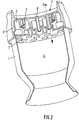
- Fig. 1 to 3 show examples of a mainstream rocket engine.
- the engine each has a combustion chamber 1, which is bounded upstream by an injection plate 2 of an injection head 3.
- injection elements 4 are arranged, which serve to direct one or more fuel flows into the interior 9 of the combustion chamber 1.
- the injection head 3 is bounded upstream by a cover plate 6.
- the injection elements 4 are either tubular, but they can also be formed by a combination of tubes and one or more coaxial sleeves.
- the injection elements 4 or the tubes or sleeves are connected to the injection plate 2 and / or the cover plate 6.
- the main flow of a gaseous fuel and turbine exhaust gases (gas) reach an antechamber 7 in front of the injection head and are then passed through the injection elements 4 into the interior 9 of the combustion chamber 1.
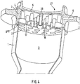
- Fig. 4 shows an expander-cycle engine, in which a gaseous fuel stream such as hydrogen (gH2) is passed into an antechamber 17 and from there via annular gaps 8 between a pipe 28 and a sleeve of a coaxial injection element 4 in the interior 9 of the combustion chamber passes , Via another chamber 27 and the tube 28, another, for example, liquid fuel stream such as liquid oxygen enters the interior 9 of the combustion chamber first
- a gaseous fuel stream such as hydrogen (gH2)
- Fig. 1 shows an arrangement of a Helmholtz resonator 5 in the wall of the antechamber 7.
- the Helmholtz resonator 5 as a circular circumferential Chamber may be formed in the wall of the prechamber 7, which is connected via an annular passage gap with the prechamber 7, as in Fig. 1 shown.
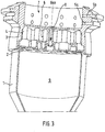
- Fig. 2 shows an alternative embodiment, wherein ⁇ / 4 resonators 5 are arranged in the form of unilaterally open cylinders in the cover plate 6 of the injection head 3. As in Fig. 2 shown, a plurality of ⁇ / 4 resonators 5 may be arranged uniformly distributed. In the case of Fig. 2 the ⁇ / 4 resonators 5 are arranged annularly around the central axis of the cover plate 6.
- ⁇ / 4 resonators 5a, 5b in the wall of the prechamber 7 is provided.
- the ⁇ / 4 resonators 5a, 5b are formed as holes in the wall of the prechamber 7. These ⁇ / 4 resonators 5a, 5b can also be distributed uniformly.
- the ⁇ / 4 resonators 5a, 5b are arranged in two superimposed rings in the wall of the prechamber 7.
- ⁇ / 4 resonators 5, 5a, 5b are basically identical in design, in order to damp exactly one defined oscillation frequency.
- the ⁇ / 4 resonators 5, 5a, 5b may be formed differently, so that in each case a group of ⁇ / 4 resonators 5, 5a, 5b is adapted to a specific oscillation frequency.
- the lower ⁇ / 4 resonators 5a are formed as shorter holes and thus adapted to higher vibration frequencies than the upper ⁇ / 4 resonators 5b, which are formed as longer holes.
- the determination of the geometrical dimensions has to take into account the respective temperature conditions of the gas in the region of the resonators, since this has a direct influence on the speed of sound and thus also on the frequency.
- ⁇ / 4 resonators 5 are provided as holes in the wall of the injection head 3 in the region of an antechamber 17, which encloses the injection elements 4.
- the ⁇ / 4 resonators 5 can be uniformly distributed, for example, annularly, be arranged in the wall of the injection head 3 and there may also be several groups of ⁇ / 4 resonators 5 with different adaptation to different vibration frequencies.
- gaseous fuel such as gH2 enters the pre-chamber 17 and is introduced via annular gaps 8 into the interior 9 of the combustion chamber 1.
- This flow path of the gaseous fuel is a vibration connection between the interior 9 of the combustion chamber 1 and the antechamber 17, analogous to the above statements to the FIGS. 1 to 3 ,
- these vibrations reach the ⁇ / 4 resonators 5 in the wall of the antechamber 17 and can be effectively attenuated there by the resonator effect of the ⁇ / 4 resonators 5.
- the essential advantage of the invention is the largely constant temperature of the gas in the resonators 5, 5a, 5b during the entire duration of the operation of the engine. Furthermore, there is a simplification of the construction in the high-temperature region of the combustion chamber 1, since in the region of the wall of the combustion chamber 1 and in the injection plate in addition to the usual cooling no further arrangements such as resonators more must be provided. In addition, the construction according to the present invention enables a much higher number of resonator examples to be accommodated, since the individual embodiments according to FIGS FIGS.
- Helmholtz resonators 5 and / or ⁇ / 4 resonators 5a, 5b in the wall of the prechamber 7 and / or ⁇ / 4 resonators 5 can be provided in the cover plate 6.
Landscapes
- Engineering & Computer Science (AREA)
- Chemical & Material Sciences (AREA)
- Combustion & Propulsion (AREA)
- Mechanical Engineering (AREA)
- General Engineering & Computer Science (AREA)
- Combustion Methods Of Internal-Combustion Engines (AREA)
Claims (3)
- Moteur de fusée, comprenant une chambre de combustion (1), un moyen pour amortir les vibrations de la chambre de combustion (1) et une préchambre (7),
dans lequel le moyen pour amortir les vibrations comprend au moins un résonateur (5, 5a, 5b) relié de manière vibratoire à la chambre de combustion (1),
dans lequel la chambre de combustion (1) est contiguë, du côté amont, à une plaque d'injection (2) d'une tête d'injection (3), au moins un élément d'injection (4) étant prévu dans la tête d'injection (3) pour introduire un flux de combustible gazeux dans la chambre de combustion (1),
dans lequel ledit au moins un résonateur (5, 5a, 5b) est disposé en liaison fluidique avec la préchambre (7) et relié de manière vibratoire à la préchambre (7),
et dans lequel la préchambre (7) est reliée de manière vibratoire à la chambre de combustion (1) par au moins un canal de passage (8),
dans lequel la préchambre (7) qui est reliée fluidiquement au flux de combustible gazeux et à partir de laquelle le flux de combustible gazeux est conduit dans la chambre de combustion (1), est prévue en amont dudit au moins un élément d'injection (4) dans la direction du flux. - Moteur de fusée, comprenant une chambre de combustion (1), une préchambre (17), une autre chambre (27) et un moyen pour amortir les vibrations de la chambre de combustion (1),
dans lequel le moyen pour amortir les vibrations comprend au moins un résonateur (5) relié de manière vibratoire à la chambre de combustion (1),
dans lequel la chambre de combustion (1) est contiguë, du côté amont, à une tête d'injection (3) qui comprend au moins un élément d'injection (4) pour introduire un premier flux de combustible dans la chambre de combustion (1),
dans lequel l'autre chambre (27) est reliée à la chambre de combustion (1) par l'élément d'injection (4) pour conduire le premier flux de combustible dans la chambre de combustion,
dans lequel ledit au moins un résonateur (5) est disposé en liaison fluidique avec la préchambre (17) et relié de manière vibratoire à la préchambre (17),
et dans lequel la préchambre (17) est reliée de manière vibratoire à la chambre de combustion (1) par au moins un canal de passage (18),
dans lequel ledit au moins un élément d'injection (4) et la préchambre (17) sont disposés fluidiquement l'un à côté de l'autre en amont de la chambre de combustion (1), et un second flux de combustible gazeux est conduit à partir de la préchambre (17) dans la chambre de combustion (1). - Moteur de fusée selon la revendication 1 ou 2,
caractérisé en ce que
le canal de passage (8, 18) est conçu comme une partie d'un élément d'injection (4).
Applications Claiming Priority (2)
| Application Number | Priority Date | Filing Date | Title |
|---|---|---|---|
| DE102004018725.8A DE102004018725B4 (de) | 2004-04-17 | 2004-04-17 | Dämpfung von Schwingungen einer Brennkammer durch Resonatoren |
| PCT/DE2005/000622 WO2005100858A1 (fr) | 2004-04-17 | 2005-04-07 | Amortissement de vibrations d'une chambre de combustion au moyen de resonateurs |
Publications (2)
| Publication Number | Publication Date |
|---|---|
| EP1738112A1 EP1738112A1 (fr) | 2007-01-03 |
| EP1738112B1 true EP1738112B1 (fr) | 2019-07-03 |
Family
ID=34964533
Family Applications (1)
| Application Number | Title | Priority Date | Filing Date |
|---|---|---|---|
| EP05732027.7A Active EP1738112B1 (fr) | 2004-04-17 | 2005-04-07 | Moteur de fusée avec amortissement de vibrations de la chambre de combustion au moyen de resonateurs |
Country Status (4)
| Country | Link |
|---|---|
| US (1) | US8033111B2 (fr) |
| EP (1) | EP1738112B1 (fr) |
| DE (1) | DE102004018725B4 (fr) |
| WO (1) | WO2005100858A1 (fr) |
Families Citing this family (14)
| Publication number | Priority date | Publication date | Assignee | Title |
|---|---|---|---|---|
| EP2187125A1 (fr) * | 2008-09-24 | 2010-05-19 | Siemens Aktiengesellschaft | Dispositif et procédé destinés à l'amortissement d'oscillations de combustion |
| US8733106B2 (en) * | 2011-05-03 | 2014-05-27 | General Electric Company | Fuel injector and support plate |
| WO2013043078A1 (fr) * | 2011-09-22 | 2013-03-28 | General Electric Company | Capuchon de chambre de combustion pour amortissement de dynamiques à basse fréquence |
| US8532847B1 (en) * | 2012-09-28 | 2013-09-10 | Fukashi Andoh | Vibration suppressing device for spacecraft |
| DE102013213860A1 (de) * | 2013-07-16 | 2015-01-22 | Siemens Aktiengesellschaft | Brennerdüsenträger mit Resonatoren |
| CN106461222B (zh) | 2014-05-19 | 2019-03-15 | 西门子公司 | 具有共振器的燃烧器装置 |
| DE102015218687A1 (de) * | 2015-09-29 | 2017-04-13 | Siemens Aktiengesellschaft | Brenneranordnung für eine Ringbrennkammer mit Resonatoren |
| DE102016209650B4 (de) | 2016-06-02 | 2019-03-14 | Arianegroup Gmbh | Einspritzvorrichtung für ein raketentriebwerk |
| DE102017127831A1 (de) | 2017-11-24 | 2019-05-29 | Arianegroup Gmbh | Einspritzkopf für ein triebwerk, triebwerk und rakete |
| DE102019110258A1 (de) | 2019-04-15 | 2020-10-15 | Deutsches Zentrum für Luft- und Raumfahrt e.V. | Injektorvorrichtung für eine Triebwerksvorrichtung, Triebwerksvorrichtung und Luft- und/oder Raumfahrzeug |
| RU2738391C2 (ru) * | 2019-04-30 | 2020-12-11 | Акционерное общество "Государственный космический научно-производственный центр имени М.В. Хруничева" | Камера сгорания |
| EP3916212B1 (fr) | 2020-05-28 | 2022-09-28 | ArianeGroup GmbH | Élément d'injection pour moteur, plaque avant pour une tête d'injecteur et procédé de fabrication d'un élément d'injection |
| CN112746910A (zh) * | 2020-10-29 | 2021-05-04 | 北京航天动力研究所 | 一种抑制高频不稳定燃烧的喷注器 |
| US11988113B2 (en) * | 2020-12-18 | 2024-05-21 | The Boeing Company | Ducted inlet for reducing flow oscillations |
Family Cites Families (17)
| Publication number | Priority date | Publication date | Assignee | Title |
|---|---|---|---|---|
| US2738781A (en) * | 1951-07-02 | 1956-03-20 | Jr Albert G Bodine | Engine detonation control by acoustic methods and apparatus |
| US3200589A (en) * | 1961-11-03 | 1965-08-17 | North American Aviation Inc | Two stage baffled injector |
| US3426409A (en) * | 1965-01-26 | 1969-02-11 | United Aircraft Corp | Method of making a tubular walled chamber |
| US3483698A (en) * | 1966-11-22 | 1969-12-16 | United Aircraft Corp | Combustion instability reduction device |
| US3782116A (en) * | 1971-03-10 | 1974-01-01 | Trw Inc | Foam cooling and acoustic damping for internal combustion engines |
| JPS52148839A (en) * | 1976-06-04 | 1977-12-10 | Hitachi Ltd | Gas burner |
| DE3432607A1 (de) * | 1984-09-05 | 1986-03-13 | Messerschmitt-Bölkow-Blohm GmbH, 8012 Ottobrunn | Einrichtung zum daempfen von brennkammerschwingungen bei fluessigkeitsraketentriebwerken |
| US4621492A (en) * | 1985-01-10 | 1986-11-11 | The United States Of America As Represented By The Administrator Of The National Aeronautics And Space Administration | Low loss injector for liquid propellant rocket engines |
| FR2685386B1 (fr) * | 1991-12-20 | 1994-03-25 | Propulsion Ste Europeenne | Systeme d'amortissement des instabilites de combustion haute frequence dans une chambre de combustion. |
| US5349813A (en) * | 1992-11-09 | 1994-09-27 | Foster Wheeler Energy Corporation | Vibration of systems comprised of hot and cold components |
| FR2698914B1 (fr) * | 1992-12-09 | 1995-03-03 | Europ Propulsion | Moteur-fusée à ergols liquides à flux dérivé et générateur de gaz intégré. |
| FR2712030B1 (fr) * | 1993-11-03 | 1996-01-26 | Europ Propulsion | Système d'injection et éléments d'injection tricoaxiaux associés. |
| US5685157A (en) * | 1995-05-26 | 1997-11-11 | General Electric Company | Acoustic damper for a gas turbine engine combustor |
| JP3962554B2 (ja) * | 2001-04-19 | 2007-08-22 | 三菱重工業株式会社 | ガスタービン燃焼器及びガスタービン |
| DE10163561B4 (de) * | 2001-12-21 | 2008-09-11 | Eads Space Transportation Gmbh | Verfahren zur Messung des dynamischen Dämpfungsverhaltens eines Raketentriebwerkes |
| US6918243B2 (en) * | 2003-05-19 | 2005-07-19 | The Boeing Company | Bi-propellant injector with flame-holding zone igniter |
| US7334408B2 (en) * | 2004-09-21 | 2008-02-26 | Siemens Aktiengesellschaft | Combustion chamber for a gas turbine with at least two resonator devices |
-
2004
- 2004-04-17 DE DE102004018725.8A patent/DE102004018725B4/de not_active Expired - Fee Related
-
2005
- 2005-04-07 WO PCT/DE2005/000622 patent/WO2005100858A1/fr active Application Filing
- 2005-04-07 EP EP05732027.7A patent/EP1738112B1/fr active Active
- 2005-04-07 US US10/599,983 patent/US8033111B2/en active Active
Non-Patent Citations (1)
| Title |
|---|
| None * |
Also Published As
| Publication number | Publication date |
|---|---|
| WO2005100858A1 (fr) | 2005-10-27 |
| DE102004018725B4 (de) | 2015-02-12 |
| EP1738112A1 (fr) | 2007-01-03 |
| US8033111B2 (en) | 2011-10-11 |
| US20080245072A1 (en) | 2008-10-09 |
| DE102004018725A1 (de) | 2005-11-10 |
Similar Documents
| Publication | Publication Date | Title |
|---|---|---|
| EP1738112B1 (fr) | Moteur de fusée avec amortissement de vibrations de la chambre de combustion au moyen de resonateurs | |
| DE102010016547B4 (de) | Injektor mit integriertem Resonator | |
| EP2340397B1 (fr) | Pièce du brûleur pour une chambre de combustion d'une turbine à gaz et turbine à gaz | |
| DE102005062284B4 (de) | Brennkammer für eine Gasturbine | |
| EP1483536B1 (fr) | Turbine a gaz | |
| DE102010017289A1 (de) | Resonatorbaugruppe zum Abschwächen dynamischer Prozesse in Gasturbinen | |
| CH701454B1 (de) | Brenner mit einem Strömungskonditionierer. | |
| DE112019004946B4 (de) | Brennerkomponente, Brenner, Gasturbine und Herstellungsverfahren für Brennerkomponente | |
| DE102010037411A1 (de) | Brennkammer-zu-Brennkammer-Modenentkopplung mittels Brennstoffaufteilungen auf Brennkammerrohrebene | |
| CH707580A2 (de) | Brennkammer mit einer Luft-Bypassanlage. | |
| EP0892217B1 (fr) | Dispositif d'atténuation des vibrations d'une chambre de combustion | |
| DE102008016931A1 (de) | System zur Reduktion der Brennkammerdynamik | |
| DE2344240A1 (de) | Treibstoff-verteilungssystem | |
| EP0971172B1 (fr) | Chambre de combustion pour turbine à gaz avec paroi à structure silencieuse | |
| WO2013029984A2 (fr) | Chambre de combustion pour une installation de turbine à gaz | |
| CH698570B1 (de) | Brennstoffdüse für eine Brennkammer. | |
| EP1605209A1 (fr) | Chambre de combustion avec dispositif d'amortissement des vibrations thermo-acoustiques | |
| DE102004041272B4 (de) | Hybridbrennerlanze | |
| DE60225411T2 (de) | Flammrohr oder Bekleidung für die Brennkammer einer Gasturbine mit niedriger Schadstoffemission | |
| DE102015113146A1 (de) | Systeme und Vorrichtungen im Zusammenhang mit Gasturbinenbrennkammern | |
| EP2187125A1 (fr) | Dispositif et procédé destinés à l'amortissement d'oscillations de combustion | |
| EP1010939B1 (fr) | Chambre de combustion avec système d'alimentation en carburant amorti acoustiquement | |
| EP0974788A1 (fr) | Dispositif d'atténuation adaptée de bruit dans une turbomachine | |
| DE69932318T2 (de) | Brennstoffeinspritzvorrichtung für eine gasturbinenbrennkammer | |
| EP2092245B1 (fr) | Brûleur pour turbine à gaz avec un écran thermique pour l'alimentation de combustible |
Legal Events
| Date | Code | Title | Description |
|---|---|---|---|
| PUAI | Public reference made under article 153(3) epc to a published international application that has entered the european phase |
Free format text: ORIGINAL CODE: 0009012 |
|
| AK | Designated contracting states |
Kind code of ref document: A1 Designated state(s): AT BE BG CH CY CZ DE DK EE ES FI FR GB GR HU IE IS IT LI LT LU MC NL PL PT RO SE SI SK TR |
|
| 17P | Request for examination filed |
Effective date: 20060811 |
|
| DAX | Request for extension of the european patent (deleted) | ||
| 17Q | First examination report despatched |
Effective date: 20160331 |
|
| RAP1 | Party data changed (applicant data changed or rights of an application transferred) |
Owner name: ARIANEGROUP GMBH |
|
| STAA | Information on the status of an ep patent application or granted ep patent |
Free format text: STATUS: EXAMINATION IS IN PROGRESS |
|
| REG | Reference to a national code |
Ref country code: DE Ref legal event code: R079 Ref document number: 502005016057 Country of ref document: DE Free format text: PREVIOUS MAIN CLASS: F23M0013000000 Ipc: F23M0020000000 |
|
| GRAP | Despatch of communication of intention to grant a patent |
Free format text: ORIGINAL CODE: EPIDOSNIGR1 |
|
| STAA | Information on the status of an ep patent application or granted ep patent |
Free format text: STATUS: GRANT OF PATENT IS INTENDED |
|
| RIC1 | Information provided on ipc code assigned before grant |
Ipc: F02K 9/62 20060101ALI20190109BHEP Ipc: F23M 20/00 20140101AFI20190109BHEP Ipc: G10K 11/172 20060101ALI20190109BHEP Ipc: F23R 3/28 20060101ALI20190109BHEP Ipc: F02K 1/82 20060101ALI20190109BHEP |
|
| INTG | Intention to grant announced |
Effective date: 20190125 |
|
| GRAS | Grant fee paid |
Free format text: ORIGINAL CODE: EPIDOSNIGR3 |
|
| GRAA | (expected) grant |
Free format text: ORIGINAL CODE: 0009210 |
|
| STAA | Information on the status of an ep patent application or granted ep patent |
Free format text: STATUS: THE PATENT HAS BEEN GRANTED |
|
| AK | Designated contracting states |
Kind code of ref document: B1 Designated state(s): AT BE BG CH CY CZ DE DK EE ES FI FR GB GR HU IE IS IT LI LT LU MC NL PL PT RO SE SI SK TR |
|
| REG | Reference to a national code |
Ref country code: GB Ref legal event code: FG4D Free format text: NOT ENGLISH |
|
| REG | Reference to a national code |
Ref country code: CH Ref legal event code: EP Ref country code: AT Ref legal event code: REF Ref document number: 1151475 Country of ref document: AT Kind code of ref document: T Effective date: 20190715 |
|
| REG | Reference to a national code |
Ref country code: DE Ref legal event code: R096 Ref document number: 502005016057 Country of ref document: DE |
|
| REG | Reference to a national code |
Ref country code: IE Ref legal event code: FG4D Free format text: LANGUAGE OF EP DOCUMENT: GERMAN |
|
| REG | Reference to a national code |
Ref country code: NL Ref legal event code: MP Effective date: 20190703 |
|
| REG | Reference to a national code |
Ref country code: LT Ref legal event code: MG4D |
|
| PG25 | Lapsed in a contracting state [announced via postgrant information from national office to epo] |
Ref country code: BG Free format text: LAPSE BECAUSE OF FAILURE TO SUBMIT A TRANSLATION OF THE DESCRIPTION OR TO PAY THE FEE WITHIN THE PRESCRIBED TIME-LIMIT Effective date: 20191003 Ref country code: PT Free format text: LAPSE BECAUSE OF FAILURE TO SUBMIT A TRANSLATION OF THE DESCRIPTION OR TO PAY THE FEE WITHIN THE PRESCRIBED TIME-LIMIT Effective date: 20191104 Ref country code: NL Free format text: LAPSE BECAUSE OF FAILURE TO SUBMIT A TRANSLATION OF THE DESCRIPTION OR TO PAY THE FEE WITHIN THE PRESCRIBED TIME-LIMIT Effective date: 20190703 Ref country code: CZ Free format text: LAPSE BECAUSE OF FAILURE TO SUBMIT A TRANSLATION OF THE DESCRIPTION OR TO PAY THE FEE WITHIN THE PRESCRIBED TIME-LIMIT Effective date: 20190703 Ref country code: LT Free format text: LAPSE BECAUSE OF FAILURE TO SUBMIT A TRANSLATION OF THE DESCRIPTION OR TO PAY THE FEE WITHIN THE PRESCRIBED TIME-LIMIT Effective date: 20190703 Ref country code: SE Free format text: LAPSE BECAUSE OF FAILURE TO SUBMIT A TRANSLATION OF THE DESCRIPTION OR TO PAY THE FEE WITHIN THE PRESCRIBED TIME-LIMIT Effective date: 20190703 Ref country code: FI Free format text: LAPSE BECAUSE OF FAILURE TO SUBMIT A TRANSLATION OF THE DESCRIPTION OR TO PAY THE FEE WITHIN THE PRESCRIBED TIME-LIMIT Effective date: 20190703 |
|
| PG25 | Lapsed in a contracting state [announced via postgrant information from national office to epo] |
Ref country code: ES Free format text: LAPSE BECAUSE OF FAILURE TO SUBMIT A TRANSLATION OF THE DESCRIPTION OR TO PAY THE FEE WITHIN THE PRESCRIBED TIME-LIMIT Effective date: 20190703 Ref country code: GR Free format text: LAPSE BECAUSE OF FAILURE TO SUBMIT A TRANSLATION OF THE DESCRIPTION OR TO PAY THE FEE WITHIN THE PRESCRIBED TIME-LIMIT Effective date: 20191004 Ref country code: IS Free format text: LAPSE BECAUSE OF FAILURE TO SUBMIT A TRANSLATION OF THE DESCRIPTION OR TO PAY THE FEE WITHIN THE PRESCRIBED TIME-LIMIT Effective date: 20191103 |
|
| PG25 | Lapsed in a contracting state [announced via postgrant information from national office to epo] |
Ref country code: TR Free format text: LAPSE BECAUSE OF FAILURE TO SUBMIT A TRANSLATION OF THE DESCRIPTION OR TO PAY THE FEE WITHIN THE PRESCRIBED TIME-LIMIT Effective date: 20190703 |
|
| PG25 | Lapsed in a contracting state [announced via postgrant information from national office to epo] |
Ref country code: RO Free format text: LAPSE BECAUSE OF FAILURE TO SUBMIT A TRANSLATION OF THE DESCRIPTION OR TO PAY THE FEE WITHIN THE PRESCRIBED TIME-LIMIT Effective date: 20190703 Ref country code: EE Free format text: LAPSE BECAUSE OF FAILURE TO SUBMIT A TRANSLATION OF THE DESCRIPTION OR TO PAY THE FEE WITHIN THE PRESCRIBED TIME-LIMIT Effective date: 20190703 Ref country code: DK Free format text: LAPSE BECAUSE OF FAILURE TO SUBMIT A TRANSLATION OF THE DESCRIPTION OR TO PAY THE FEE WITHIN THE PRESCRIBED TIME-LIMIT Effective date: 20190703 Ref country code: PL Free format text: LAPSE BECAUSE OF FAILURE TO SUBMIT A TRANSLATION OF THE DESCRIPTION OR TO PAY THE FEE WITHIN THE PRESCRIBED TIME-LIMIT Effective date: 20190703 |
|
| PG25 | Lapsed in a contracting state [announced via postgrant information from national office to epo] |
Ref country code: SK Free format text: LAPSE BECAUSE OF FAILURE TO SUBMIT A TRANSLATION OF THE DESCRIPTION OR TO PAY THE FEE WITHIN THE PRESCRIBED TIME-LIMIT Effective date: 20190703 Ref country code: IS Free format text: LAPSE BECAUSE OF FAILURE TO SUBMIT A TRANSLATION OF THE DESCRIPTION OR TO PAY THE FEE WITHIN THE PRESCRIBED TIME-LIMIT Effective date: 20200224 |
|
| REG | Reference to a national code |
Ref country code: DE Ref legal event code: R097 Ref document number: 502005016057 Country of ref document: DE |
|
| PLBE | No opposition filed within time limit |
Free format text: ORIGINAL CODE: 0009261 |
|
| STAA | Information on the status of an ep patent application or granted ep patent |
Free format text: STATUS: NO OPPOSITION FILED WITHIN TIME LIMIT |
|
| PG2D | Information on lapse in contracting state deleted |
Ref country code: IS |
|
| 26N | No opposition filed |
Effective date: 20200603 |
|
| PG25 | Lapsed in a contracting state [announced via postgrant information from national office to epo] |
Ref country code: SI Free format text: LAPSE BECAUSE OF FAILURE TO SUBMIT A TRANSLATION OF THE DESCRIPTION OR TO PAY THE FEE WITHIN THE PRESCRIBED TIME-LIMIT Effective date: 20190703 |
|
| PG25 | Lapsed in a contracting state [announced via postgrant information from national office to epo] |
Ref country code: MC Free format text: LAPSE BECAUSE OF FAILURE TO SUBMIT A TRANSLATION OF THE DESCRIPTION OR TO PAY THE FEE WITHIN THE PRESCRIBED TIME-LIMIT Effective date: 20190703 |
|
| REG | Reference to a national code |
Ref country code: CH Ref legal event code: PL |
|
| PG25 | Lapsed in a contracting state [announced via postgrant information from national office to epo] |
Ref country code: CH Free format text: LAPSE BECAUSE OF NON-PAYMENT OF DUE FEES Effective date: 20200430 Ref country code: LU Free format text: LAPSE BECAUSE OF NON-PAYMENT OF DUE FEES Effective date: 20200407 Ref country code: LI Free format text: LAPSE BECAUSE OF NON-PAYMENT OF DUE FEES Effective date: 20200430 |
|
| REG | Reference to a national code |
Ref country code: BE Ref legal event code: MM Effective date: 20200430 |
|
| PG25 | Lapsed in a contracting state [announced via postgrant information from national office to epo] |
Ref country code: BE Free format text: LAPSE BECAUSE OF NON-PAYMENT OF DUE FEES Effective date: 20200430 |
|
| PG25 | Lapsed in a contracting state [announced via postgrant information from national office to epo] |
Ref country code: IE Free format text: LAPSE BECAUSE OF NON-PAYMENT OF DUE FEES Effective date: 20200407 |
|
| REG | Reference to a national code |
Ref country code: AT Ref legal event code: MM01 Ref document number: 1151475 Country of ref document: AT Kind code of ref document: T Effective date: 20200407 |
|
| PG25 | Lapsed in a contracting state [announced via postgrant information from national office to epo] |
Ref country code: AT Free format text: LAPSE BECAUSE OF NON-PAYMENT OF DUE FEES Effective date: 20200407 |
|
| PG25 | Lapsed in a contracting state [announced via postgrant information from national office to epo] |
Ref country code: CY Free format text: LAPSE BECAUSE OF FAILURE TO SUBMIT A TRANSLATION OF THE DESCRIPTION OR TO PAY THE FEE WITHIN THE PRESCRIBED TIME-LIMIT Effective date: 20190703 |
|
| PGFP | Annual fee paid to national office [announced via postgrant information from national office to epo] |
Ref country code: IT Payment date: 20220420 Year of fee payment: 18 Ref country code: GB Payment date: 20220420 Year of fee payment: 18 Ref country code: FR Payment date: 20220421 Year of fee payment: 18 |
|
| P01 | Opt-out of the competence of the unified patent court (upc) registered |
Effective date: 20230612 |
|
| PGFP | Annual fee paid to national office [announced via postgrant information from national office to epo] |
Ref country code: DE Payment date: 20230420 Year of fee payment: 19 |
|
| GBPC | Gb: european patent ceased through non-payment of renewal fee |
Effective date: 20230407 |
|
| PG25 | Lapsed in a contracting state [announced via postgrant information from national office to epo] |
Ref country code: GB Free format text: LAPSE BECAUSE OF NON-PAYMENT OF DUE FEES Effective date: 20230407 |
|
| PG25 | Lapsed in a contracting state [announced via postgrant information from national office to epo] |
Ref country code: GB Free format text: LAPSE BECAUSE OF NON-PAYMENT OF DUE FEES Effective date: 20230407 Ref country code: FR Free format text: LAPSE BECAUSE OF NON-PAYMENT OF DUE FEES Effective date: 20230430 |
|
| PG25 | Lapsed in a contracting state [announced via postgrant information from national office to epo] |
Ref country code: IT Free format text: LAPSE BECAUSE OF NON-PAYMENT OF DUE FEES Effective date: 20230407 |