EP1737927B1 - Werkzeug zum zerkleinern von koks - Google Patents
Werkzeug zum zerkleinern von koks Download PDFInfo
- Publication number
- EP1737927B1 EP1737927B1 EP20050729841 EP05729841A EP1737927B1 EP 1737927 B1 EP1737927 B1 EP 1737927B1 EP 20050729841 EP20050729841 EP 20050729841 EP 05729841 A EP05729841 A EP 05729841A EP 1737927 B1 EP1737927 B1 EP 1737927B1
- Authority
- EP
- European Patent Office
- Prior art keywords
- valve
- tool
- cutting
- drilling
- tool according
- Prior art date
- Legal status (The legal status is an assumption and is not a legal conclusion. Google has not performed a legal analysis and makes no representation as to the accuracy of the status listed.)
- Expired - Lifetime
Links
Images


Classifications
-
- C—CHEMISTRY; METALLURGY
- C10—PETROLEUM, GAS OR COKE INDUSTRIES; TECHNICAL GASES CONTAINING CARBON MONOXIDE; FUELS; LUBRICANTS; PEAT
- C10B—DESTRUCTIVE DISTILLATION OF CARBONACEOUS MATERIALS FOR PRODUCTION OF GAS, COKE, TAR, OR SIMILAR MATERIALS
- C10B33/00—Discharging devices; Coke guides
- C10B33/006—Decoking tools, e.g. hydraulic coke removing tools with boring or cutting nozzles
-
- B—PERFORMING OPERATIONS; TRANSPORTING
- B26—HAND CUTTING TOOLS; CUTTING; SEVERING
- B26F—PERFORATING; PUNCHING; CUTTING-OUT; STAMPING-OUT; SEVERING BY MEANS OTHER THAN CUTTING
- B26F3/00—Severing by means other than cutting; Apparatus therefor
- B26F3/004—Severing by means other than cutting; Apparatus therefor by means of a fluid jet
-
- Y—GENERAL TAGGING OF NEW TECHNOLOGICAL DEVELOPMENTS; GENERAL TAGGING OF CROSS-SECTIONAL TECHNOLOGIES SPANNING OVER SEVERAL SECTIONS OF THE IPC; TECHNICAL SUBJECTS COVERED BY FORMER USPC CROSS-REFERENCE ART COLLECTIONS [XRACs] AND DIGESTS
- Y10—TECHNICAL SUBJECTS COVERED BY FORMER USPC
- Y10T—TECHNICAL SUBJECTS COVERED BY FORMER US CLASSIFICATION
- Y10T137/00—Fluid handling
- Y10T137/8593—Systems
- Y10T137/86493—Multi-way valve unit
- Y10T137/86718—Dividing into parallel flow paths with recombining
- Y10T137/86743—Rotary
-
- Y—GENERAL TAGGING OF NEW TECHNOLOGICAL DEVELOPMENTS; GENERAL TAGGING OF CROSS-SECTIONAL TECHNOLOGIES SPANNING OVER SEVERAL SECTIONS OF THE IPC; TECHNICAL SUBJECTS COVERED BY FORMER USPC CROSS-REFERENCE ART COLLECTIONS [XRACs] AND DIGESTS
- Y10—TECHNICAL SUBJECTS COVERED BY FORMER USPC
- Y10T—TECHNICAL SUBJECTS COVERED BY FORMER US CLASSIFICATION
- Y10T137/00—Fluid handling
- Y10T137/8593—Systems
- Y10T137/87056—With selective motion for plural valve actuator
Definitions
- This so-called “de-coking” is usually carried out with high-pressure water jets, which crush the coke and wash out of the drums.
- the tool for generating these high-pressure water jets is introduced via a drill string from above into the drum.
- the “de-coking” is carried out in two sections. First, an opening is drilled through the tool in the drum from top to bottom, then the tool is returned to the top of the drum and the coke is then crushed by high pressure jets of water generated by the cutting nozzles at approximately right angles to the axis ,
- the tool for example, from the generic WO 03/014261 A1
- the drilling nozzles send high pressure water jets substantially parallel or at an acute angle to an axis formed by the boring bar and the opening created during drilling.
- the cutting nozzles produce high pressure water jets which are oriented substantially at right angles or at a shallow angle to the axis formed by the drill rod and the opening in the drum.
- the changeover between the operating states drilling and cutting must be quick and easy.
- the nozzles used in the tool due to the high water pressure, wear and tear and must be replaced regularly. Accordingly, the tool must be designed so that replacement of the nozzles can be made quickly and safely.
- Increases the wear of the nozzles are characterized by the fact that the water is pressed in known tools of the type mentioned under high pressure in an associated with all nozzles annulus, from where the water passes undirected into the respective open nozzles, with no alignment the flow takes place in the direction of the respective nozzles.
- the invention has for its object to provide a tool for Zerldeinern coke, which has a particularly simple structure and safe to use and to maintain.
- Characteristic of the tool according to the invention are at least two flow channels formed within the housing, each extending between each of the respective flow channel associated inflow openings and the respective cutting and drilling nozzles.
- the valve for controlling the direction of flow of the water to the cutting nozzles or the drilling nozzles is arranged in the region of the inflow opening and closes depending on the operating condition, usually cutting or drilling, the corresponding inflow openings of the individual flow channels.
- the flow channels which in the context of the invention are self-contained regions which extend between the inflow openings and the outlet openings arranged in the region of the associated nozzles, make it possible to supply the water to the respective nozzles with only very small flow losses. Due to the associated reduction of the disturbing influences acting on the nozzles, the service life of the individual nozzles compared to conventional tools can be significantly increased.
- the inventive design also allows the increase in the life of the associated with the tool parts, such. B. a supply pump by reducing the pump power.
- Another advantage of the tool according to the invention results from the fact that the closed to control the direction of flow of the water inflow can be combined at any constructive advantageous point of the tool, so that a plurality of independently arrangeable nozzles can be controlled using a single valve ,
- this is advantageously designed for the two operating states cutting and drilling, wherein in the operating state cutting the inflow openings to the drilling nozzle and in the operating state drilling the inflow opening is closed to the cutting nozzle through the valve.
- This development of the invention makes it possible to reduce the number of valves required to close the inflow valve body in the valve, so that the valve can be particularly simple, which in particular leads to a complementary reduction in manufacturing costs and increases the reliability of the tool in a complementary manner.
- the arrangement of the flow channels and the inflow openings in the tool can be freely selected according to the design and hydrodynamic specifications.
- the inflow openings are arranged substantially perpendicular to the flow direction of the water flowing through the drill rod and the housing.
- the flow direction will correspond to the longitudinal axis of the tool and the boring bar, so that the inflow openings then extend transversely to the longitudinal axis of the tool.
- the flow channels can be formed integrally with the housing.
- a simplification of the production is, however, according to an advantageous embodiment of the invention achieved in that the flow channels are formed in an insertable into the housing insert.
- the arrangement of the insert is preferably carried out so that no water between the Insert and the housing inner wall flows past and possibly leads to a disturbance of the main flow. This is preferably achieved by a positive and positive connection of the insert and the housing of the tool using screws or the like.
- a separate insert also makes it possible to use a deviating from the material for the housing material, which is particularly suitable for the design of the flow channels, but is used due to possibly higher costs only to a limited extent for the production of the housing.
- An additional improvement of the flow through the housing can be achieved in that at the nozzle-facing ends of the flow channels flow straightener are arranged, which improve the flow behavior of the water through the nozzles in a complementary manner.
- the valve for regulating the flow through the inflow openings can basically have arbitrarily designed valve bodies. According to an advantageous development of the invention, however, the valve has, at least in sections, a spherically formed valve body closing the inflow openings in the respective selected operating state.
- the spherical formation of the surface sections ensures that the access to the respective inflow opening to be closed is securely sealed against the passage of liquids.
- a circular disc whose one side is spherically curved would, for example, fully meet the requirements of closing the inflow openings.
- the valve body has at least two spherical surface portions and are preferably formed symmetrically.
- these spherical surface sections are opposite each other, z. B. as domes, which adjoin each other with their maximum extent.
- the symmetrical design of the valve body has the advantage that they can be performed in the valve simply because of the symmetry.
- they have the advantage that, should a first spherical surface section z. B. wear traces, the symmetrical valve body can be easily turned. Then, in each case a different dome with a second spherical surface portion can be used to seal the inflow openings.
- valve body which can be omitted due to the complete symmetry on a positional security of the valve body
- the symmetrical valve bodies then give preference when the diameter of the valve body direct impact on the dimensions of Tool has, since such valve body have a smaller thickness than spherical valve body.
- the valve is mounted inside the housing and has means for guiding, in particular half-shells, which surround the valve bodies, which are in engagement with the inflow openings.
- the means for guiding the valve body are arranged in the valve, which, however, does not generally completely fill the housing. Accordingly, there are free spaces between the valve and the housing. According to an advantageous development of the invention, these free spaces are in connection with the interior of the tool, so that the liquid flowing through the tool in the operating state can also flow through these free spaces.
- the advantage of this arrangement is that there is no pressure gradient between the interior and the free spaces between the housing and the valve in the tool. Accordingly, the valve can be designed to save material, because no pressure differences with the corresponding pressure and tensile forces must be absorbed. In addition, the avoidance of pressure differences ensures smooth operation operate the valve.
- the arrangement of the valve can be carried out in a preferred manner in the form that the valve body are automatically pressed by the pressure prevailing in the housing internal pressure on the inflow openings to be closed.
- the valve bodies are biased by a spring element in the direction of the inflow opening.
- the changeover from the operating state "drilling" to the other operating state “cutting” takes place manually with most known tools.
- the tool is withdrawn from the drum after the first operation, and a device disposed inside the tool is actuated, which closes the downwardly directed drilling nozzles after the completion of drilling and opens the cutting nozzles.
- This device for closing one or more nozzles is on the one hand with the valve in engagement and on the other hand has a receiving opening for a control element which is to be actuated from outside the tool.
- the device for actuating the valve in the boring bar facing area namely arranged above the nozzle, so that even in case of failure of any control and warning devices the operator can safely approach the tool without the risk of serious injury.
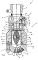
- Fig. 1 shows a tool 2 with a housing 4, four nozzles 34, 41 - two nozzles 41 for drilling coke, two nozzles 34 for cutting coke - only two of which are shown, a four flow channels 31, 47 having insert 30 and a valve 20 for opening and closing arranged on the insert 30 inflow openings 32, 37 (see. Fig. 4 ).
- the tool 2 hangs in the operating state on a drill rod, not shown, and is introduced into a filled with coke drum.
- Information such as “above” or “below” refer to the in the Fig. 1 and 3 shown tool 2 and in the in the Fig. 2 and the Fig. 4-12 shown items on the longitudinal axis A, which is aligned with the boring bar (top) and one of the tool 2 to be produced bore (bottom, not shown).
- the housing 4 is formed in two parts and consists of the upper housing half 4a and the lower housing half 4b, which are interconnected by using screws 7 extending through the lower housing half 4b and engaging in tapped holes in the upper housing half 4a.
- a cavity 50 in the lower housing half 4b ensures the unimpeded flow of fluid through the flow channels 31 to the drilling nozzles 41, which are arranged in corresponding bores 48 in the lower housing half 4b and secured by screws 42 in position.
- the upper housing half 4a is attached with a flange 5 with the interposition of a ring seal 6 liquid-tight to the drill rod.
- the upper housing half 4a extends from there as a substantially cylindrical hollow body to the lower housing half 4b.
- a circular shoulder 51 is formed at the end of the upper casing half 4a, which faces the lower casing half 4b.
- 51 is located in the lower region of the upper housing half 4a arranged insert 30 with a flange 27 on the upper housing half 4a.
- annular seals 36 for sealing the interior and for sealing the connection of the lower half of the housing 4b and the upper half of the housing 4a arranged in corresponding grooves 29 (see. Fig. 5 ).
- a seal 35 is inserted into an annular groove 28 extending in the upper region of the insert 30 and seals the arrangement of the insert 30 in the upper housing half 4a in its upper region.
- a bore 39 for receiving a positioning pin 38 is further arranged, which is arranged in the installed position of the insert 30 in the upper housing half 4a partially in a corresponding bore in the upper housing half 4a.
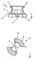
- insert 30 has at its end facing the drill rod four inflow openings 32, 37, each offset by 90 ° the circular end of the insert 30 are arranged. In each case two opposite inflow openings 32, 37 lead to the cutting nozzles 34, or to the cavity 50 arranged in front of the drilling nozzles 41.
- the inflow openings 32 form the beginning of two flow channels 47, which have a curved course and terminate at outlet openings 33 arranged in front of the cutting nozzles 34 arranged diametrically on the tool 2.
- the insert 30 in the area behind the outlet openings 33 - also viewed in the flow direction - a correspondingly shaped receiving opening 49.
- the cutting nozzles 34 themselves are arranged in corresponding bores 45 in the upper housing half 4a and secured by screws 46.
- the inflow openings 37 form the beginning of two further flow channels 31, which extend separately and opposite to the cavity 50.
- the flow channels 31 in this case have a rounded cross-section, which tapers and widened from the inflow openings 37 to the cavity 50.
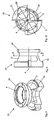
- Fig. 3 and 6 illustrated sectional view in the plane of the cutting nozzles 34 shows the location of the approximately smallest cross-section of the flow channels 31st
- valve 20 is rotatably disposed in the housing upper part 4a.
- the valve 20 rests with an annular shoulder 54 on its peripheral surface on a correspondingly formed contact surface 52 in the upper housing part 4a and is thus fixed in the direction of the boring bar (see. Fig. 8-12 ).
- the valve housing 21 is formed at its end facing the insert 30 in the form of a cylindrical hollow body in which a half-shell support 8 is formed, which extends substantially perpendicular to the longitudinal axis of the tool 2.
- the half-shell support 8 has two half shells 25 arranged opposite one another for receiving valve bodies 26, the half shells 25 embracing the valve bodies 26 in the upper region and thus securing the position of the valve bodies 26 in the radial direction of the tool 2.
- the valve bodies 26 are disc-shaped and have opposing spherical surface portions, which are adapted to the shape of the inflow openings 32, 37.
- the half-shell support 8 itself is shaped such that in a plane transverse to the longitudinal axis of the housing 4, two opposing regions adjoining the half-shells 25 each release an approximately 90 ° wide angular range for the flow through the valve 20.
- the valve housing 21 has an upwardly tapered annular portion, to which a cylindrically shaped annular flange 19 connects, which has eight holes 9 for connection to a bevel gear 22, which are designed to receive screws 24, which extend through the holes 9 in correspondingly formed thread in the bevel gear 22, and so connect this firmly with the valve housing 21.
- FIG. 1 shown tool 2 is in the operating state "drilling" (drilling state).
- the valve body 26 of the valve 20 lock the inflow openings 32 on the insert 30.
- the diameter of the valve body 26 is dimensioned so that the inflow openings 32 are reliably and completely covered.
- the inflow openings 37 of the insert 30 are freely accessible. Water, which shoots into the tool 2 under high pressure from the drill rod, flows through the interior in the tool 2 above the valve 20, through this and the inflow openings 37 and the subsequent flow channels 31, then passes through the cavity 50 in the lower housing half 4b to finally exit through the drilling nozzles 41 into a non-illustrated, coke-filled drum.
- an actuating device 10 for actuating the valve 20 in the tool 2 is provided.
- the actuator 10 has a perpendicular to the axis A through the upper housing half 4b extending shaft 12, at whose arranged in the interior of the tool 2 end a bevel gear 11 is arranged, which is in engagement with the bevel gear 22 at the top of the valve 20.
- the shaft 12 has a tool receiving opening 13 which is adapted to receive a hand lever, by means of which the shaft 12 and the bevel gear 11 can be rotated.
- the shaft 12 itself is mounted in an insert member 18 which is secured in a bore 17 in the upper housing half 4a using a ring seal 15 and screws 14 extending through the insert member 18 into the upper housing half 4a on the upper housing half 4a.
- Another seal 16 seals off the shaft 13 in the insert element 18.
- the bevel gear 11 is actuated by rotating the shaft 12 using a hand lever adapted to the tool receiving opening 13.
- the standing with the gear 11 via the gear 22 in engagement valve 20 is rotated by the gear 11 in the upper housing half 4a about the axis A. Together with the valve housing 21, the bevel gear 22 and thus also the valve body 26 of the valve 20 is rotated.
- valve bodies 26 By turning the valve 20 on the upper end of the insert 30, the valve bodies 26, which closed the inflow openings 32 to the flow channels 47 leading to the cutting nozzles 34, are released.
- the valve body 26 migrate by operating the tool receiving opening 13 on a circular arc by 90 ° until the inflow openings 37 are completely closed.
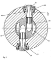
- Fig. 2 shows the tool 2 in the operating state of the cutting. From the boring bar, water and the high pressure flow into the interior of the upper housing half 4a and now pass through the inflow openings 32 into the flow channels 47 and then through the cutting nozzles 34.
- the inflow openings 37 are securely and completely closed by the valve bodies 26 arranged above them.
- the closing action of the valve body 26 is secured in this position as well as when closing the access openings 32 in that the extremely high water pressure, which is well above 100 bar, the valve body 26 into the inflow openings 32, 37 hineinpreßt.
Landscapes
- Chemical & Material Sciences (AREA)
- Engineering & Computer Science (AREA)
- Forests & Forestry (AREA)
- Mechanical Engineering (AREA)
- Materials Engineering (AREA)
- Oil, Petroleum & Natural Gas (AREA)
- Organic Chemistry (AREA)
- Life Sciences & Earth Sciences (AREA)
- Earth Drilling (AREA)
- Coke Industry (AREA)
- Nozzles (AREA)
- Cutting Tools, Boring Holders, And Turrets (AREA)
- Drilling Tools (AREA)
- Lift Valve (AREA)
- Crushing And Grinding (AREA)
- Disintegrating Or Milling (AREA)
- Working-Up Tar And Pitch (AREA)
Applications Claiming Priority (2)
| Application Number | Priority Date | Filing Date | Title |
|---|---|---|---|
| DE200410020013 DE102004020013B3 (de) | 2004-04-21 | 2004-04-21 | Werkzeug zum Zerkleinern von Koks |
| PCT/EP2005/003727 WO2005105953A1 (de) | 2004-04-21 | 2005-04-08 | Wekzeug zum zerkleinern von koks |
Publications (2)
| Publication Number | Publication Date |
|---|---|
| EP1737927A1 EP1737927A1 (de) | 2007-01-03 |
| EP1737927B1 true EP1737927B1 (de) | 2008-09-24 |
Family
ID=34965304
Family Applications (1)
| Application Number | Title | Priority Date | Filing Date |
|---|---|---|---|
| EP20050729841 Expired - Lifetime EP1737927B1 (de) | 2004-04-21 | 2005-04-08 | Werkzeug zum zerkleinern von koks |
Country Status (13)
| Country | Link |
|---|---|
| US (2) | US8074745B2 (enExample) |
| EP (1) | EP1737927B1 (enExample) |
| JP (1) | JP2007533803A (enExample) |
| CN (1) | CN1954045B (enExample) |
| AT (1) | ATE409216T1 (enExample) |
| BR (1) | BRPI0510120A (enExample) |
| CA (1) | CA2563813C (enExample) |
| DE (2) | DE102004020013B3 (enExample) |
| EA (1) | EA008917B1 (enExample) |
| ES (1) | ES2313320T3 (enExample) |
| HR (1) | HRP20080675T3 (enExample) |
| MX (1) | MXPA06012063A (enExample) |
| WO (1) | WO2005105953A1 (enExample) |
Families Citing this family (10)
| Publication number | Priority date | Publication date | Assignee | Title |
|---|---|---|---|---|
| DE102007063329B3 (de) * | 2007-12-28 | 2009-06-04 | Ruhrpumpen Gmbh | Werkzeug zum Zerkleinern von Koks |
| DE102007063330B4 (de) * | 2007-12-28 | 2009-09-24 | Ruhrpumpen Gmbh | Werkzeug zum Zerkleinern von Koks |
| US8002204B2 (en) | 2007-12-31 | 2011-08-23 | Ruhrpumpen Gmbh | Decoking tool |
| US7819343B2 (en) | 2007-12-31 | 2010-10-26 | Ruhrpumpen Gmbh | Decoking tool |
| DE202009006232U1 (de) | 2009-04-30 | 2009-08-13 | Ruhrpumpen Gmbh | Werkzeug zum Schneiden von Koks und anderem harten Material in Behältern |
| US10077403B2 (en) * | 2009-05-04 | 2018-09-18 | Flowserve Management Company | Nozzles for a fluid jet decoking tool |
| US8066334B2 (en) | 2009-07-17 | 2011-11-29 | Ruhrpumpen Gmbh | Tool for cutting coke and other hard materials in drums |
| RU2534078C2 (ru) | 2010-09-23 | 2014-11-27 | Рурпумпен Гмбх | Инструмент для измельчения кокса |
| CN102517048B (zh) * | 2012-01-10 | 2013-06-19 | 洛阳涧光石化设备有限公司 | 一种回转体型结构的自动除焦器 |
| CN110645380B (zh) * | 2019-11-07 | 2025-07-22 | 天地科技股份有限公司上海分公司 | 水阀 |
Family Cites Families (8)
| Publication number | Priority date | Publication date | Assignee | Title |
|---|---|---|---|---|
| US3804186A (en) * | 1973-04-20 | 1974-04-16 | W Schoeffler | Valved jet device for well drills |
| SU1120693A1 (ru) * | 1982-04-23 | 1985-05-30 | Предприятие П/Я В-2223 | Гидравлический резак ГРУ-3М |
| SU1234414A2 (ru) * | 1984-12-25 | 1986-05-30 | Предприятие П/Я В-2223 | Гидравлический резак |
| FR2640992B1 (enExample) * | 1988-12-26 | 1993-07-02 | Inst Francais Du Petrole | |
| US4923021A (en) * | 1988-12-30 | 1990-05-08 | Conoco Inc. | Combination bit for coking oven |
| US5816505A (en) * | 1997-04-17 | 1998-10-06 | Ingersoll-Dresser Pump Company | Fluid jet decoking tool |
| US6349763B1 (en) * | 1999-08-20 | 2002-02-26 | Halliburton Energy Services, Inc. | Electrical surface activated downhole circulating sub |
| WO2003014261A1 (de) * | 2001-07-23 | 2003-02-20 | Ruhrpumpen Gmbh | Entkokungswerkzeug |
-
2004
- 2004-04-21 DE DE200410020013 patent/DE102004020013B3/de not_active Expired - Fee Related
-
2005
- 2005-04-08 DE DE200550005470 patent/DE502005005470D1/de not_active Expired - Lifetime
- 2005-04-08 CN CN2005800124643A patent/CN1954045B/zh not_active Expired - Fee Related
- 2005-04-08 ES ES05729841T patent/ES2313320T3/es not_active Expired - Lifetime
- 2005-04-08 WO PCT/EP2005/003727 patent/WO2005105953A1/de not_active Ceased
- 2005-04-08 MX MXPA06012063A patent/MXPA06012063A/es unknown
- 2005-04-08 HR HR20080675T patent/HRP20080675T3/xx unknown
- 2005-04-08 US US11/578,456 patent/US8074745B2/en active Active
- 2005-04-08 JP JP2007508760A patent/JP2007533803A/ja not_active Abandoned
- 2005-04-08 AT AT05729841T patent/ATE409216T1/de not_active IP Right Cessation
- 2005-04-08 CA CA 2563813 patent/CA2563813C/en not_active Expired - Fee Related
- 2005-04-08 BR BRPI0510120-4A patent/BRPI0510120A/pt not_active IP Right Cessation
- 2005-04-08 EP EP20050729841 patent/EP1737927B1/de not_active Expired - Lifetime
- 2005-04-08 EA EA200601928A patent/EA008917B1/ru not_active IP Right Cessation
-
2008
- 2008-04-30 US US12/112,066 patent/US8074746B2/en not_active Expired - Lifetime
Also Published As
| Publication number | Publication date |
|---|---|
| HRP20080675T3 (en) | 2009-02-28 |
| JP2007533803A (ja) | 2007-11-22 |
| DE102004020013B3 (de) | 2005-12-22 |
| EA008917B1 (ru) | 2007-08-31 |
| CN1954045B (zh) | 2010-06-02 |
| CA2563813A1 (en) | 2005-11-10 |
| MXPA06012063A (es) | 2007-01-25 |
| US8074746B2 (en) | 2011-12-13 |
| US20080067858A1 (en) | 2008-03-20 |
| CA2563813C (en) | 2010-07-13 |
| EP1737927A1 (de) | 2007-01-03 |
| WO2005105953A1 (de) | 2005-11-10 |
| EA200601928A1 (ru) | 2007-02-27 |
| DE502005005470D1 (de) | 2008-11-06 |
| US8074745B2 (en) | 2011-12-13 |
| ATE409216T1 (de) | 2008-10-15 |
| BRPI0510120A (pt) | 2007-09-25 |
| ES2313320T3 (es) | 2009-03-01 |
| CN1954045A (zh) | 2007-04-25 |
| US20080271766A1 (en) | 2008-11-06 |
Similar Documents
| Publication | Publication Date | Title |
|---|---|---|
| DE102006043879B4 (de) | Vorrichtung zum absperren und steuern des wasserauslasses auseinem sprenger sowie betätigungsanordnung hierfür | |
| DE3126507A1 (de) | "armatur" | |
| EP1409608B1 (de) | Entkokungswerkzeug | |
| DE3139824A1 (de) | Kugelventil | |
| EP0715692B1 (de) | Pumpenschutzventil | |
| EP1737927B1 (de) | Werkzeug zum zerkleinern von koks | |
| EP3259506A1 (de) | Ventil zum steuern des wasserflusses in einer sanitärleitung | |
| EP0061415A1 (de) | Ventil für hydraulische Systeme | |
| EP0054602B1 (de) | Eigenmediumgesteuertes Absperrventil | |
| DE102007041753A1 (de) | Vorrichtung zur Drosselung des freien Querschnittes einer Dampfleitung oder dergleichen | |
| EP0622574A2 (de) | Betätigungsvorrichtung für ein drehbares Verschlussstück eines Ventils | |
| WO2007134702A1 (de) | Vorrichtung zum flüssigkeitsabrasivsuspensionsstrahlen | |
| EP2352938B1 (de) | Scheibenventil mit leckagesicherung | |
| DE3239930A1 (de) | Hydraulisch steuerbares sperrventil, insbesondere fuer die rohrbruchsicherung | |
| DE4234037C2 (de) | Ventilanordnung, insbesondere für mobile Arbeitsgeräte | |
| EP2400190B1 (de) | Drehkegelventil | |
| DE3003480C2 (enExample) | ||
| DE19729053B4 (de) | Düse zur Staubbekämpfung im untertägigen Berg- und Tunnelbau mit einer staubbindenden Flüssigkeit | |
| DE2458321B2 (de) | Stellventil | |
| DE102007063330B4 (de) | Werkzeug zum Zerkleinern von Koks | |
| WO2002092955A2 (de) | Erdbohrvorrichtung | |
| EP3916276B1 (de) | Ventileinrichtung und wasserabrasiv-suspensionsschneideeinrichtung | |
| DE2907565A1 (de) | Kombinierte selbstschluss- und mischarmatur | |
| DE2213587C3 (de) | Drosselklappe | |
| EP1078195A1 (de) | Anbohrarmatur für unter druck stehende rohrleitungen |
Legal Events
| Date | Code | Title | Description |
|---|---|---|---|
| PUAI | Public reference made under article 153(3) epc to a published international application that has entered the european phase |
Free format text: ORIGINAL CODE: 0009012 |
|
| 17P | Request for examination filed |
Effective date: 20061110 |
|
| AK | Designated contracting states |
Kind code of ref document: A1 Designated state(s): AT BE BG CH CY CZ DE DK EE ES FI FR GB GR HU IE IS IT LI LT LU MC NL PL PT RO SE SI SK TR |
|
| AX | Request for extension of the european patent |
Extension state: HR |
|
| RIN1 | Information on inventor provided before grant (corrected) |
Inventor name: OZIMEK, MATTHIAS, C/O RUHRPUMPEN EGYPT, Inventor name: PAUL, WOLFGANG Inventor name: HEIDEMANN, DIRK Inventor name: BARCIKOWSKI, MACIEJ |
|
| RAX | Requested extension states of the european patent have changed |
Extension state: HR Payment date: 20061115 |
|
| GRAP | Despatch of communication of intention to grant a patent |
Free format text: ORIGINAL CODE: EPIDOSNIGR1 |
|
| RIC1 | Information provided on ipc code assigned before grant |
Ipc: C10B 33/00 20060101AFI20080215BHEP |
|
| GRAS | Grant fee paid |
Free format text: ORIGINAL CODE: EPIDOSNIGR3 |
|
| GRAA | (expected) grant |
Free format text: ORIGINAL CODE: 0009210 |
|
| AK | Designated contracting states |
Kind code of ref document: B1 Designated state(s): AT BE BG CH CY CZ DE DK EE ES FI FR GB GR HU IE IS IT LI LT LU MC NL PL PT RO SE SI SK TR |
|
| AX | Request for extension of the european patent |
Extension state: HR |
|
| REG | Reference to a national code |
Ref country code: GB Ref legal event code: FG4D Free format text: NOT ENGLISH |
|
| REG | Reference to a national code |
Ref country code: CH Ref legal event code: EP |
|
| REG | Reference to a national code |
Ref country code: IE Ref legal event code: FG4D Free format text: LANGUAGE OF EP DOCUMENT: GERMAN |
|
| REF | Corresponds to: |
Ref document number: 502005005470 Country of ref document: DE Date of ref document: 20081106 Kind code of ref document: P |
|
| REG | Reference to a national code |
Ref country code: RO Ref legal event code: EPE |
|
| REG | Reference to a national code |
Ref country code: SE Ref legal event code: TRGR |
|
| REG | Reference to a national code |
Ref country code: HR Ref legal event code: TUEP Ref document number: P20080675 Country of ref document: HR |
|
| PG25 | Lapsed in a contracting state [announced via postgrant information from national office to epo] |
Ref country code: LT Free format text: LAPSE BECAUSE OF FAILURE TO SUBMIT A TRANSLATION OF THE DESCRIPTION OR TO PAY THE FEE WITHIN THE PRESCRIBED TIME-LIMIT Effective date: 20080924 |
|
| PG25 | Lapsed in a contracting state [announced via postgrant information from national office to epo] |
Ref country code: SI Free format text: LAPSE BECAUSE OF FAILURE TO SUBMIT A TRANSLATION OF THE DESCRIPTION OR TO PAY THE FEE WITHIN THE PRESCRIBED TIME-LIMIT Effective date: 20080924 |
|
| REG | Reference to a national code |
Ref country code: HR Ref legal event code: T1PR Ref document number: P20080675 Country of ref document: HR |
|
| REG | Reference to a national code |
Ref country code: ES Ref legal event code: FG2A Ref document number: 2313320 Country of ref document: ES Kind code of ref document: T3 |
|
| NLV1 | Nl: lapsed or annulled due to failure to fulfill the requirements of art. 29p and 29m of the patents act | ||
| REG | Reference to a national code |
Ref country code: IE Ref legal event code: FD4D |
|
| PG25 | Lapsed in a contracting state [announced via postgrant information from national office to epo] |
Ref country code: BG Free format text: LAPSE BECAUSE OF FAILURE TO SUBMIT A TRANSLATION OF THE DESCRIPTION OR TO PAY THE FEE WITHIN THE PRESCRIBED TIME-LIMIT Effective date: 20081224 |
|
| PG25 | Lapsed in a contracting state [announced via postgrant information from national office to epo] |
Ref country code: IS Free format text: LAPSE BECAUSE OF FAILURE TO SUBMIT A TRANSLATION OF THE DESCRIPTION OR TO PAY THE FEE WITHIN THE PRESCRIBED TIME-LIMIT Effective date: 20090124 Ref country code: CZ Free format text: LAPSE BECAUSE OF FAILURE TO SUBMIT A TRANSLATION OF THE DESCRIPTION OR TO PAY THE FEE WITHIN THE PRESCRIBED TIME-LIMIT Effective date: 20080924 Ref country code: PT Free format text: LAPSE BECAUSE OF FAILURE TO SUBMIT A TRANSLATION OF THE DESCRIPTION OR TO PAY THE FEE WITHIN THE PRESCRIBED TIME-LIMIT Effective date: 20090224 Ref country code: SK Free format text: LAPSE BECAUSE OF FAILURE TO SUBMIT A TRANSLATION OF THE DESCRIPTION OR TO PAY THE FEE WITHIN THE PRESCRIBED TIME-LIMIT Effective date: 20080924 Ref country code: NL Free format text: LAPSE BECAUSE OF FAILURE TO SUBMIT A TRANSLATION OF THE DESCRIPTION OR TO PAY THE FEE WITHIN THE PRESCRIBED TIME-LIMIT Effective date: 20080924 |
|
| PG25 | Lapsed in a contracting state [announced via postgrant information from national office to epo] |
Ref country code: DK Free format text: LAPSE BECAUSE OF FAILURE TO SUBMIT A TRANSLATION OF THE DESCRIPTION OR TO PAY THE FEE WITHIN THE PRESCRIBED TIME-LIMIT Effective date: 20080924 Ref country code: IE Free format text: LAPSE BECAUSE OF FAILURE TO SUBMIT A TRANSLATION OF THE DESCRIPTION OR TO PAY THE FEE WITHIN THE PRESCRIBED TIME-LIMIT Effective date: 20080924 Ref country code: EE Free format text: LAPSE BECAUSE OF FAILURE TO SUBMIT A TRANSLATION OF THE DESCRIPTION OR TO PAY THE FEE WITHIN THE PRESCRIBED TIME-LIMIT Effective date: 20080924 |
|
| PLBE | No opposition filed within time limit |
Free format text: ORIGINAL CODE: 0009261 |
|
| STAA | Information on the status of an ep patent application or granted ep patent |
Free format text: STATUS: NO OPPOSITION FILED WITHIN TIME LIMIT |
|
| 26N | No opposition filed |
Effective date: 20090625 |
|
| REG | Reference to a national code |
Ref country code: HR Ref legal event code: PBON Ref document number: P20080675 Country of ref document: HR Effective date: 20090409 |
|
| BERE | Be: lapsed |
Owner name: RUHRPUMPEN G.M.B.H. Effective date: 20090430 |
|
| REG | Reference to a national code |
Ref country code: CH Ref legal event code: PL |
|
| EUG | Se: european patent has lapsed | ||
| GBPC | Gb: european patent ceased through non-payment of renewal fee |
Effective date: 20090408 |
|
| REG | Reference to a national code |
Ref country code: FR Ref legal event code: ST Effective date: 20091231 |
|
| PG25 | Lapsed in a contracting state [announced via postgrant information from national office to epo] |
Ref country code: CH Free format text: LAPSE BECAUSE OF NON-PAYMENT OF DUE FEES Effective date: 20090430 Ref country code: LI Free format text: LAPSE BECAUSE OF NON-PAYMENT OF DUE FEES Effective date: 20090430 Ref country code: FI Free format text: LAPSE BECAUSE OF NON-PAYMENT OF DUE FEES Effective date: 20090408 |
|
| PG25 | Lapsed in a contracting state [announced via postgrant information from national office to epo] |
Ref country code: MC Free format text: LAPSE BECAUSE OF NON-PAYMENT OF DUE FEES Effective date: 20090430 Ref country code: GB Free format text: LAPSE BECAUSE OF NON-PAYMENT OF DUE FEES Effective date: 20090408 Ref country code: FR Free format text: LAPSE BECAUSE OF NON-PAYMENT OF DUE FEES Effective date: 20091222 Ref country code: RO Free format text: LAPSE BECAUSE OF NON-PAYMENT OF DUE FEES Effective date: 20080924 |
|
| PG25 | Lapsed in a contracting state [announced via postgrant information from national office to epo] |
Ref country code: BE Free format text: LAPSE BECAUSE OF NON-PAYMENT OF DUE FEES Effective date: 20090430 Ref country code: PL Free format text: LAPSE BECAUSE OF FAILURE TO SUBMIT A TRANSLATION OF THE DESCRIPTION OR TO PAY THE FEE WITHIN THE PRESCRIBED TIME-LIMIT Effective date: 20080924 |
|
| REG | Reference to a national code |
Ref country code: ES Ref legal event code: FD2A Effective date: 20090411 |
|
| PG25 | Lapsed in a contracting state [announced via postgrant information from national office to epo] |
Ref country code: ES Free format text: LAPSE BECAUSE OF NON-PAYMENT OF DUE FEES Effective date: 20090411 |
|
| PG25 | Lapsed in a contracting state [announced via postgrant information from national office to epo] |
Ref country code: AT Free format text: LAPSE BECAUSE OF NON-PAYMENT OF DUE FEES Effective date: 20090408 |
|
| PG25 | Lapsed in a contracting state [announced via postgrant information from national office to epo] |
Ref country code: GR Free format text: LAPSE BECAUSE OF FAILURE TO SUBMIT A TRANSLATION OF THE DESCRIPTION OR TO PAY THE FEE WITHIN THE PRESCRIBED TIME-LIMIT Effective date: 20081225 |
|
| PG25 | Lapsed in a contracting state [announced via postgrant information from national office to epo] |
Ref country code: IT Free format text: LAPSE BECAUSE OF NON-PAYMENT OF DUE FEES Effective date: 20090408 |
|
| PG25 | Lapsed in a contracting state [announced via postgrant information from national office to epo] |
Ref country code: LU Free format text: LAPSE BECAUSE OF NON-PAYMENT OF DUE FEES Effective date: 20090408 |
|
| PG25 | Lapsed in a contracting state [announced via postgrant information from national office to epo] |
Ref country code: SE Free format text: LAPSE BECAUSE OF NON-PAYMENT OF DUE FEES Effective date: 20090409 |
|
| PG25 | Lapsed in a contracting state [announced via postgrant information from national office to epo] |
Ref country code: HU Free format text: LAPSE BECAUSE OF FAILURE TO SUBMIT A TRANSLATION OF THE DESCRIPTION OR TO PAY THE FEE WITHIN THE PRESCRIBED TIME-LIMIT Effective date: 20090325 |
|
| PG25 | Lapsed in a contracting state [announced via postgrant information from national office to epo] |
Ref country code: TR Free format text: LAPSE BECAUSE OF FAILURE TO SUBMIT A TRANSLATION OF THE DESCRIPTION OR TO PAY THE FEE WITHIN THE PRESCRIBED TIME-LIMIT Effective date: 20080924 |
|
| PG25 | Lapsed in a contracting state [announced via postgrant information from national office to epo] |
Ref country code: CY Free format text: LAPSE BECAUSE OF FAILURE TO SUBMIT A TRANSLATION OF THE DESCRIPTION OR TO PAY THE FEE WITHIN THE PRESCRIBED TIME-LIMIT Effective date: 20080924 |
|
| PGFP | Annual fee paid to national office [announced via postgrant information from national office to epo] |
Ref country code: DE Payment date: 20170427 Year of fee payment: 13 |
|
| REG | Reference to a national code |
Ref country code: DE Ref legal event code: R119 Ref document number: 502005005470 Country of ref document: DE |
|
| PG25 | Lapsed in a contracting state [announced via postgrant information from national office to epo] |
Ref country code: DE Free format text: LAPSE BECAUSE OF NON-PAYMENT OF DUE FEES Effective date: 20181101 |