EP1737765B1 - Behälter zur aufnahme von medien sowie verfahren zur herstellung und zum überprüfen der dichtheit des behälters - Google Patents
Behälter zur aufnahme von medien sowie verfahren zur herstellung und zum überprüfen der dichtheit des behälters Download PDFInfo
- Publication number
- EP1737765B1 EP1737765B1 EP05736532A EP05736532A EP1737765B1 EP 1737765 B1 EP1737765 B1 EP 1737765B1 EP 05736532 A EP05736532 A EP 05736532A EP 05736532 A EP05736532 A EP 05736532A EP 1737765 B1 EP1737765 B1 EP 1737765B1
- Authority
- EP
- European Patent Office
- Prior art keywords
- container
- segments
- pressure
- wall
- segment
- Prior art date
- Legal status (The legal status is an assumption and is not a legal conclusion. Google has not performed a legal analysis and makes no representation as to the accuracy of the status listed.)
- Not-in-force
Links
Images


Classifications
-
- B—PERFORMING OPERATIONS; TRANSPORTING
- B29—WORKING OF PLASTICS; WORKING OF SUBSTANCES IN A PLASTIC STATE IN GENERAL
- B29C—SHAPING OR JOINING OF PLASTICS; SHAPING OF MATERIAL IN A PLASTIC STATE, NOT OTHERWISE PROVIDED FOR; AFTER-TREATMENT OF THE SHAPED PRODUCTS, e.g. REPAIRING
- B29C65/00—Joining or sealing of preformed parts, e.g. welding of plastics materials; Apparatus therefor
- B29C65/82—Testing the joint
-
- B—PERFORMING OPERATIONS; TRANSPORTING
- B29—WORKING OF PLASTICS; WORKING OF SUBSTANCES IN A PLASTIC STATE IN GENERAL
- B29C—SHAPING OR JOINING OF PLASTICS; SHAPING OF MATERIAL IN A PLASTIC STATE, NOT OTHERWISE PROVIDED FOR; AFTER-TREATMENT OF THE SHAPED PRODUCTS, e.g. REPAIRING
- B29C65/00—Joining or sealing of preformed parts, e.g. welding of plastics materials; Apparatus therefor
- B29C65/02—Joining or sealing of preformed parts, e.g. welding of plastics materials; Apparatus therefor by heating, with or without pressure
-
- B—PERFORMING OPERATIONS; TRANSPORTING
- B29—WORKING OF PLASTICS; WORKING OF SUBSTANCES IN A PLASTIC STATE IN GENERAL
- B29C—SHAPING OR JOINING OF PLASTICS; SHAPING OF MATERIAL IN A PLASTIC STATE, NOT OTHERWISE PROVIDED FOR; AFTER-TREATMENT OF THE SHAPED PRODUCTS, e.g. REPAIRING
- B29C65/00—Joining or sealing of preformed parts, e.g. welding of plastics materials; Apparatus therefor
- B29C65/48—Joining or sealing of preformed parts, e.g. welding of plastics materials; Apparatus therefor using adhesives, i.e. using supplementary joining material; solvent bonding
- B29C65/4805—Joining or sealing of preformed parts, e.g. welding of plastics materials; Apparatus therefor using adhesives, i.e. using supplementary joining material; solvent bonding characterised by the type of adhesives
- B29C65/481—Non-reactive adhesives, e.g. physically hardening adhesives
- B29C65/4815—Hot melt adhesives, e.g. thermoplastic adhesives
-
- B—PERFORMING OPERATIONS; TRANSPORTING
- B29—WORKING OF PLASTICS; WORKING OF SUBSTANCES IN A PLASTIC STATE IN GENERAL
- B29C—SHAPING OR JOINING OF PLASTICS; SHAPING OF MATERIAL IN A PLASTIC STATE, NOT OTHERWISE PROVIDED FOR; AFTER-TREATMENT OF THE SHAPED PRODUCTS, e.g. REPAIRING
- B29C65/00—Joining or sealing of preformed parts, e.g. welding of plastics materials; Apparatus therefor
- B29C65/82—Testing the joint
- B29C65/8207—Testing the joint by mechanical methods
- B29C65/8246—Pressure tests, e.g. hydrostatic pressure tests
-
- B—PERFORMING OPERATIONS; TRANSPORTING
- B29—WORKING OF PLASTICS; WORKING OF SUBSTANCES IN A PLASTIC STATE IN GENERAL
- B29C—SHAPING OR JOINING OF PLASTICS; SHAPING OF MATERIAL IN A PLASTIC STATE, NOT OTHERWISE PROVIDED FOR; AFTER-TREATMENT OF THE SHAPED PRODUCTS, e.g. REPAIRING
- B29C66/00—General aspects of processes or apparatus for joining preformed parts
- B29C66/01—General aspects dealing with the joint area or with the area to be joined
- B29C66/03—After-treatments in the joint area
- B29C66/038—Covering the joint by a coating material
-
- B—PERFORMING OPERATIONS; TRANSPORTING
- B29—WORKING OF PLASTICS; WORKING OF SUBSTANCES IN A PLASTIC STATE IN GENERAL
- B29C—SHAPING OR JOINING OF PLASTICS; SHAPING OF MATERIAL IN A PLASTIC STATE, NOT OTHERWISE PROVIDED FOR; AFTER-TREATMENT OF THE SHAPED PRODUCTS, e.g. REPAIRING
- B29C66/00—General aspects of processes or apparatus for joining preformed parts
- B29C66/01—General aspects dealing with the joint area or with the area to be joined
- B29C66/05—Particular design of joint configurations
- B29C66/10—Particular design of joint configurations particular design of the joint cross-sections
- B29C66/11—Joint cross-sections comprising a single joint-segment, i.e. one of the parts to be joined comprising a single joint-segment in the joint cross-section
- B29C66/114—Single butt joints
- B29C66/1142—Single butt to butt joints
-
- B—PERFORMING OPERATIONS; TRANSPORTING
- B29—WORKING OF PLASTICS; WORKING OF SUBSTANCES IN A PLASTIC STATE IN GENERAL
- B29C—SHAPING OR JOINING OF PLASTICS; SHAPING OF MATERIAL IN A PLASTIC STATE, NOT OTHERWISE PROVIDED FOR; AFTER-TREATMENT OF THE SHAPED PRODUCTS, e.g. REPAIRING
- B29C66/00—General aspects of processes or apparatus for joining preformed parts
- B29C66/50—General aspects of joining tubular articles; General aspects of joining long products, i.e. bars or profiled elements; General aspects of joining single elements to tubular articles, hollow articles or bars; General aspects of joining several hollow-preforms to form hollow or tubular articles
- B29C66/51—Joining tubular articles, profiled elements or bars; Joining single elements to tubular articles, hollow articles or bars; Joining several hollow-preforms to form hollow or tubular articles
- B29C66/54—Joining several hollow-preforms, e.g. half-shells, to form hollow articles, e.g. for making balls, containers; Joining several hollow-preforms, e.g. half-cylinders, to form tubular articles
-
- B—PERFORMING OPERATIONS; TRANSPORTING
- B29—WORKING OF PLASTICS; WORKING OF SUBSTANCES IN A PLASTIC STATE IN GENERAL
- B29C—SHAPING OR JOINING OF PLASTICS; SHAPING OF MATERIAL IN A PLASTIC STATE, NOT OTHERWISE PROVIDED FOR; AFTER-TREATMENT OF THE SHAPED PRODUCTS, e.g. REPAIRING
- B29C66/00—General aspects of processes or apparatus for joining preformed parts
- B29C66/70—General aspects of processes or apparatus for joining preformed parts characterised by the composition, physical properties or the structure of the material of the parts to be joined; Joining with non-plastics material
- B29C66/72—General aspects of processes or apparatus for joining preformed parts characterised by the composition, physical properties or the structure of the material of the parts to be joined; Joining with non-plastics material characterised by the structure of the material of the parts to be joined
- B29C66/723—General aspects of processes or apparatus for joining preformed parts characterised by the composition, physical properties or the structure of the material of the parts to be joined; Joining with non-plastics material characterised by the structure of the material of the parts to be joined being multi-layered
- B29C66/7234—General aspects of processes or apparatus for joining preformed parts characterised by the composition, physical properties or the structure of the material of the parts to be joined; Joining with non-plastics material characterised by the structure of the material of the parts to be joined being multi-layered comprising a barrier layer
-
- B—PERFORMING OPERATIONS; TRANSPORTING
- B29—WORKING OF PLASTICS; WORKING OF SUBSTANCES IN A PLASTIC STATE IN GENERAL
- B29C—SHAPING OR JOINING OF PLASTICS; SHAPING OF MATERIAL IN A PLASTIC STATE, NOT OTHERWISE PROVIDED FOR; AFTER-TREATMENT OF THE SHAPED PRODUCTS, e.g. REPAIRING
- B29C67/00—Shaping techniques not covered by groups B29C39/00 - B29C65/00, B29C70/00 or B29C73/00
- B29C67/004—Closing perforations or small holes, e.g. using additional moulding material
-
- B—PERFORMING OPERATIONS; TRANSPORTING
- B65—CONVEYING; PACKING; STORING; HANDLING THIN OR FILAMENTARY MATERIAL
- B65D—CONTAINERS FOR STORAGE OR TRANSPORT OF ARTICLES OR MATERIALS, e.g. BAGS, BARRELS, BOTTLES, BOXES, CANS, CARTONS, CRATES, DRUMS, JARS, TANKS, HOPPERS, FORWARDING CONTAINERS; ACCESSORIES, CLOSURES, OR FITTINGS THEREFOR; PACKAGING ELEMENTS; PACKAGES
- B65D88/00—Large containers
- B65D88/02—Large containers rigid
- B65D88/06—Large containers rigid cylindrical
-
- B—PERFORMING OPERATIONS; TRANSPORTING
- B65—CONVEYING; PACKING; STORING; HANDLING THIN OR FILAMENTARY MATERIAL
- B65D—CONTAINERS FOR STORAGE OR TRANSPORT OF ARTICLES OR MATERIALS, e.g. BAGS, BARRELS, BOTTLES, BOXES, CANS, CARTONS, CRATES, DRUMS, JARS, TANKS, HOPPERS, FORWARDING CONTAINERS; ACCESSORIES, CLOSURES, OR FITTINGS THEREFOR; PACKAGING ELEMENTS; PACKAGES
- B65D90/00—Component parts, details or accessories for large containers
- B65D90/02—Wall construction
- B65D90/08—Interconnections of wall parts; Sealing means therefor
-
- G—PHYSICS
- G01—MEASURING; TESTING
- G01M—TESTING STATIC OR DYNAMIC BALANCE OF MACHINES OR STRUCTURES; TESTING OF STRUCTURES OR APPARATUS, NOT OTHERWISE PROVIDED FOR
- G01M3/00—Investigating fluid-tightness of structures
- G01M3/02—Investigating fluid-tightness of structures by using fluid or vacuum
- G01M3/26—Investigating fluid-tightness of structures by using fluid or vacuum by measuring rate of loss or gain of fluid, e.g. by pressure-responsive devices, by flow detectors
- G01M3/32—Investigating fluid-tightness of structures by using fluid or vacuum by measuring rate of loss or gain of fluid, e.g. by pressure-responsive devices, by flow detectors for containers, e.g. radiators
- G01M3/3236—Investigating fluid-tightness of structures by using fluid or vacuum by measuring rate of loss or gain of fluid, e.g. by pressure-responsive devices, by flow detectors for containers, e.g. radiators by monitoring the interior space of the containers
- G01M3/3272—Investigating fluid-tightness of structures by using fluid or vacuum by measuring rate of loss or gain of fluid, e.g. by pressure-responsive devices, by flow detectors for containers, e.g. radiators by monitoring the interior space of the containers for verifying the internal pressure of closed containers
-
- B—PERFORMING OPERATIONS; TRANSPORTING
- B29—WORKING OF PLASTICS; WORKING OF SUBSTANCES IN A PLASTIC STATE IN GENERAL
- B29C—SHAPING OR JOINING OF PLASTICS; SHAPING OF MATERIAL IN A PLASTIC STATE, NOT OTHERWISE PROVIDED FOR; AFTER-TREATMENT OF THE SHAPED PRODUCTS, e.g. REPAIRING
- B29C59/00—Surface shaping of articles, e.g. embossing; Apparatus therefor
- B29C59/14—Surface shaping of articles, e.g. embossing; Apparatus therefor by plasma treatment
-
- B—PERFORMING OPERATIONS; TRANSPORTING
- B29—WORKING OF PLASTICS; WORKING OF SUBSTANCES IN A PLASTIC STATE IN GENERAL
- B29C—SHAPING OR JOINING OF PLASTICS; SHAPING OF MATERIAL IN A PLASTIC STATE, NOT OTHERWISE PROVIDED FOR; AFTER-TREATMENT OF THE SHAPED PRODUCTS, e.g. REPAIRING
- B29C65/00—Joining or sealing of preformed parts, e.g. welding of plastics materials; Apparatus therefor
- B29C65/48—Joining or sealing of preformed parts, e.g. welding of plastics materials; Apparatus therefor using adhesives, i.e. using supplementary joining material; solvent bonding
- B29C65/52—Joining or sealing of preformed parts, e.g. welding of plastics materials; Apparatus therefor using adhesives, i.e. using supplementary joining material; solvent bonding characterised by the way of applying the adhesive
- B29C65/54—Joining or sealing of preformed parts, e.g. welding of plastics materials; Apparatus therefor using adhesives, i.e. using supplementary joining material; solvent bonding characterised by the way of applying the adhesive between pre-assembled parts
-
- B—PERFORMING OPERATIONS; TRANSPORTING
- B29—WORKING OF PLASTICS; WORKING OF SUBSTANCES IN A PLASTIC STATE IN GENERAL
- B29C—SHAPING OR JOINING OF PLASTICS; SHAPING OF MATERIAL IN A PLASTIC STATE, NOT OTHERWISE PROVIDED FOR; AFTER-TREATMENT OF THE SHAPED PRODUCTS, e.g. REPAIRING
- B29C66/00—General aspects of processes or apparatus for joining preformed parts
- B29C66/01—General aspects dealing with the joint area or with the area to be joined
- B29C66/02—Preparation of the material, in the area to be joined, prior to joining or welding
- B29C66/022—Mechanical pre-treatments, e.g. reshaping
-
- B—PERFORMING OPERATIONS; TRANSPORTING
- B29—WORKING OF PLASTICS; WORKING OF SUBSTANCES IN A PLASTIC STATE IN GENERAL
- B29C—SHAPING OR JOINING OF PLASTICS; SHAPING OF MATERIAL IN A PLASTIC STATE, NOT OTHERWISE PROVIDED FOR; AFTER-TREATMENT OF THE SHAPED PRODUCTS, e.g. REPAIRING
- B29C66/00—General aspects of processes or apparatus for joining preformed parts
- B29C66/01—General aspects dealing with the joint area or with the area to be joined
- B29C66/05—Particular design of joint configurations
- B29C66/10—Particular design of joint configurations particular design of the joint cross-sections
- B29C66/11—Joint cross-sections comprising a single joint-segment, i.e. one of the parts to be joined comprising a single joint-segment in the joint cross-section
- B29C66/116—Single bevelled joints, i.e. one of the parts to be joined being bevelled in the joint area
-
- B—PERFORMING OPERATIONS; TRANSPORTING
- B29—WORKING OF PLASTICS; WORKING OF SUBSTANCES IN A PLASTIC STATE IN GENERAL
- B29C—SHAPING OR JOINING OF PLASTICS; SHAPING OF MATERIAL IN A PLASTIC STATE, NOT OTHERWISE PROVIDED FOR; AFTER-TREATMENT OF THE SHAPED PRODUCTS, e.g. REPAIRING
- B29C66/00—General aspects of processes or apparatus for joining preformed parts
- B29C66/01—General aspects dealing with the joint area or with the area to be joined
- B29C66/05—Particular design of joint configurations
- B29C66/10—Particular design of joint configurations particular design of the joint cross-sections
- B29C66/12—Joint cross-sections combining only two joint-segments; Tongue and groove joints; Tenon and mortise joints; Stepped joint cross-sections
- B29C66/122—Joint cross-sections combining only two joint-segments, i.e. one of the parts to be joined comprising only two joint-segments in the joint cross-section
- B29C66/1226—Joint cross-sections combining only two joint-segments, i.e. one of the parts to be joined comprising only two joint-segments in the joint cross-section comprising at least one bevelled joint-segment
- B29C66/12261—Joint cross-sections combining only two joint-segments, i.e. one of the parts to be joined comprising only two joint-segments in the joint cross-section comprising at least one bevelled joint-segment the two joint-segments being bevelled, e.g. the two joint-segments forming a V
-
- B—PERFORMING OPERATIONS; TRANSPORTING
- B29—WORKING OF PLASTICS; WORKING OF SUBSTANCES IN A PLASTIC STATE IN GENERAL
- B29C—SHAPING OR JOINING OF PLASTICS; SHAPING OF MATERIAL IN A PLASTIC STATE, NOT OTHERWISE PROVIDED FOR; AFTER-TREATMENT OF THE SHAPED PRODUCTS, e.g. REPAIRING
- B29C66/00—General aspects of processes or apparatus for joining preformed parts
- B29C66/40—General aspects of joining substantially flat articles, e.g. plates, sheets or web-like materials; Making flat seams in tubular or hollow articles; Joining single elements to substantially flat surfaces
- B29C66/41—Joining substantially flat articles ; Making flat seams in tubular or hollow articles
- B29C66/43—Joining a relatively small portion of the surface of said articles
-
- B—PERFORMING OPERATIONS; TRANSPORTING
- B29—WORKING OF PLASTICS; WORKING OF SUBSTANCES IN A PLASTIC STATE IN GENERAL
- B29C—SHAPING OR JOINING OF PLASTICS; SHAPING OF MATERIAL IN A PLASTIC STATE, NOT OTHERWISE PROVIDED FOR; AFTER-TREATMENT OF THE SHAPED PRODUCTS, e.g. REPAIRING
- B29C66/00—General aspects of processes or apparatus for joining preformed parts
- B29C66/70—General aspects of processes or apparatus for joining preformed parts characterised by the composition, physical properties or the structure of the material of the parts to be joined; Joining with non-plastics material
- B29C66/71—General aspects of processes or apparatus for joining preformed parts characterised by the composition, physical properties or the structure of the material of the parts to be joined; Joining with non-plastics material characterised by the composition of the plastics material of the parts to be joined
-
- B—PERFORMING OPERATIONS; TRANSPORTING
- B29—WORKING OF PLASTICS; WORKING OF SUBSTANCES IN A PLASTIC STATE IN GENERAL
- B29L—INDEXING SCHEME ASSOCIATED WITH SUBCLASS B29C, RELATING TO PARTICULAR ARTICLES
- B29L2009/00—Layered products
-
- B—PERFORMING OPERATIONS; TRANSPORTING
- B29—WORKING OF PLASTICS; WORKING OF SUBSTANCES IN A PLASTIC STATE IN GENERAL
- B29L—INDEXING SCHEME ASSOCIATED WITH SUBCLASS B29C, RELATING TO PARTICULAR ARTICLES
- B29L2024/00—Articles with hollow walls
-
- B—PERFORMING OPERATIONS; TRANSPORTING
- B29—WORKING OF PLASTICS; WORKING OF SUBSTANCES IN A PLASTIC STATE IN GENERAL
- B29L—INDEXING SCHEME ASSOCIATED WITH SUBCLASS B29C, RELATING TO PARTICULAR ARTICLES
- B29L2031/00—Other particular articles
- B29L2031/712—Containers; Packaging elements or accessories, Packages
- B29L2031/7126—Containers; Packaging elements or accessories, Packages large, e.g. for bulk storage
-
- Y—GENERAL TAGGING OF NEW TECHNOLOGICAL DEVELOPMENTS; GENERAL TAGGING OF CROSS-SECTIONAL TECHNOLOGIES SPANNING OVER SEVERAL SECTIONS OF THE IPC; TECHNICAL SUBJECTS COVERED BY FORMER USPC CROSS-REFERENCE ART COLLECTIONS [XRACs] AND DIGESTS
- Y10—TECHNICAL SUBJECTS COVERED BY FORMER USPC
- Y10T—TECHNICAL SUBJECTS COVERED BY FORMER US CLASSIFICATION
- Y10T156/00—Adhesive bonding and miscellaneous chemical manufacture
- Y10T156/10—Methods of surface bonding and/or assembly therefor
Definitions
- the invention relates to a double-walled container which is composed of at least two interconnected segments. Furthermore, the invention relates to a method for checking the tightness of a container for receiving preferably liquid media. This method is used to monitor the container, which is composed of at least two segments which are welded together at at least one joint. Furthermore, the invention relates to a container, the inside of which is coated with a barrier layer, and a method for producing such a container.
- the container comprises two shell-like end parts each having an annular, flat connection surface and at least one sleeve-like middle part composed of at least two ring segments, which also has two annular and planar connection surfaces and a filling and emptying opening. Both the end parts and the ring segments of the middle part are made by blow molding. In the area of their connection surfaces, the parts are connected to each other by an internal and external welding. Both the two end parts and the ring segments in the region of their connection surfaces have a circumferential chamber. The connecting surfaces merge at their peripheral boundary edges in receding ramps to form welding grooves between the end portions and / or ring segments of the middle part over.
- Containers with increased leakage requirements require a monitoring system to detect leaks.
- Containers with increased leakage requirements serve e.g. for the underground storage of dangerous goods.
- the monitoring system is used to detect leaks immediately after their occurrence and to initiate measures to minimize damage.
- such monitoring takes place at least in double-shell containers with the aid of a so-called vacuum monitoring device.
- vacuum monitoring device the production of double-walled blow-molded plastic containers, especially with a large volume, not possible with reasonable effort.
- Underground hazardous goods storage containers eg fuel oil storage containers
- underground hazardous goods storage containers must be resistant to permeation of volatile hydrocarbon compounds.
- a resistance is required in order not to contaminate the soil surrounding the container, in particular, with escaping hydrocarbon compounds.
- plastic containers with a Permeationssperre wherein the inner wall of the container is subjected to a fluorination process.
- fluorination takes place in fluorination chambers, wherein at least one fluorination chamber corresponding to the container size is required to fluorinate the container.
- the object of the invention is to provide a container, a method for producing a container and a method for monitoring the tightness of a container, wherein the container can be easily and inexpensively manufactured and the tightness of the container can be determined in a simple manner.
- the tightness of the welded joints can be controlled by monitoring the pressure rise.
- the correct execution of the welded joints and thus the tightness of the container is checked in a simple manner.
- a second aspect of the invention relates to a double-walled container, which preferably serves for the storage of dangerous goods.
- the container is composed of at least two interconnected segments.
- Each segment comprises a substantially rigid plastic molding having an inner shell and an outer shell.
- the inner shell of the plastic molded part of the segment is arranged at a distance from the outer shell of the plastic molded part such that an inner space is present between the two shells.
- the first and second plastic moldings are connected to each other such that at least one gas-tight sealed interior space between the inner shell and outer shell of the container is present.
- an apparatus is provided for generating and monitoring an internal pressure different from the ambient pressure in the at least one closed interior.
- the tightness of the inner and outer shells is monitored and / or monitored by monitoring the internal pressure.
- a continuous monitoring of the internal pressure and leaks can be detected, which occur only when using the container, which then immediately measures to minimize damage or to prevent damage can be initiated.
- this safety requirements for the storage of dangerous goods can be met.
- a third aspect of the invention relates to a method for monitoring the tightness of a container which is suitable for the storage of dangerous goods.
- the container is composed of at least two segments, each segment containing a substantially rigid plastic molded part with an inner shell and an outer shell.
- the inner shell of the plastic molded part of a segment is in each case arranged at a distance to the outer shell of the same plastic molded part.
- the segments are connected to one another in such a way that at least one gas-tight closed interior space is created between the inner shell and the outer shell of the container.
- An internal pressure different from the ambient pressure is applied in the at least one interior space. A change in the internal pressure is monitored.
- a fourth aspect of the invention relates to a further container, which preferably serves for the storage of hazardous substances.
- the container is made of at least two Segments assembled, each segment containing at least one plastic molding, which comprises at least one container wall. A part of the inner surface of the container is formed by the container walls.
- the container wall of the first segment and the container wall of the second segment each contain a gas-tight barrier layer.
- the container wall of the first and the container wall of the second segment are connected to each other by a welded joint, wherein in the supplied during welding filler material at least a portion of a barrier material for a gas-tight barrier layer is included.
- the welded connection is designed in such a way that the wall of the container formed by the container walls and the welded connection has a closed barrier layer.
- this plastic container is suitable for the storage of substances which require a barrier layer on the inner wall of the container, in particular to prevent a permeation of substances through the container wall.
- a fifth aspect of the invention relates to a method for producing a container, which preferably serves for the storage and transport of hazardous substances.
- the container is composed of at least two segments, each segment containing a plastic molding comprising at least one container wall. A part of the inner surface of the container is formed by the container walls.
- a gas-tight barrier layer is generated in each case through the container wall of the first segment and the container wall of the second segment.
- the container wall of the first and the container wall of the second segment is connected by means of a welded joint, wherein an additional material is supplied during welding, which contains at least a portion of a barrier material for a gas-tight barrier layer.
- the welded connection is carried out in such a way that the container walls with the welded connection have a closed barrier layer after the completion of the welded connection.
- a sixth aspect of the invention relates to a double-walled container, preferably for the storage of dangerous goods.
- the container has a first shell composed of at least two segments, each segment containing at least one plastic molding.
- the container has a second shell, which is arranged to the first shell, that between the shells a space is enclosed gas-tight. Furthermore, a device for monitoring the gas-tightness of the enclosed space is provided.
- Such a container is inexpensive to manufacture and can be relatively easily tested for leaks.
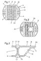
- FIGS 1 and 2 are views of a large-volume container for storage of liquid media, in particular of hazardous substances represented.
- a container can also be used for storage of rainwater or other non-hazardous media and for storage of particular powdered media.
- Large-volume containers have a volume of at least 0.5 m 3 .
- Large-volume containers with several m 3 volume up to several 10 m 3 volume are also referred to as a tank.
- the plastic container 1 has a cylindrical hollow central part 2, which is connected at its two end faces 3, each with an end portion 4, whereby the end portions 3 and the middle portion 2 form a closed container 1.
- the middle part 2 is composed of three ring segments 2a, 2b, 2c, wherein both the ring segments 2a, 2b, 2c and the two end parts 4 by means of welded joints are so firmly connected together that a closed, dense container 1 is generated.
- the three ring segments 2a, 2b, 2c and the two end portions 4 include stiffening ribs 5, which have substantially the same cross section. However, the length of the stiffening ribs 5 may be formed differently long depending on the position of the stiffening rib 5 on the container 1 and the static requirements of the container 1.
- a filling and emptying opening 6 is formed at the upper ring segment 2c of the middle part.
- the stiffening ribs 5 are arranged on the outer wall surfaces, whereby the inside of the container 1 has a substantially smooth surface. By the stiffening ribs 5 a deformation of the container 1 during filling and by external force, for example, after the introduction of the container 1 into the soil prevented.
- the smooth container inside allows easy emptying and easy cleaning of the container. 1
- FIG. 3 two abutting stiffening ribs 5 are shown, which are formed at the edges of abutting segments 2 and 4 of the container 1.
- the stiffening ribs 5 contain chambers 7, which have been produced in one piece with the respective segment 2a, 2b, 2c or with the end part 4 in the production of the ring segments 2a, 2b, 2c and the end parts 4 in the so-called blowing process.
- For the preparation of the ring segments 2a, 2b, 2c and the end parts 4 in the blow molding process is based on the already mentioned international patent application WO 01/07342 A1 which is hereby incorporated by reference into the present specification.
- the ring segment 2a and the end part 4 are fixedly connected to one another with the aid of an inner welded connection 16 and an outer welded connection 17, wherein at least the weld 16 is designed as a continuous weld seam and thus a tight connection exists between the ring segment 2a and the end part 4.
- the end portion 4 and the ring segment 2a each have an inner wall 10 and an outer wall 11.
- At the abutting edges of the stiffening ribs 5 of the end portion 4 and the ring segment 2a slopes are provided, the abutting the end portion 4 to the ring segment 2a respectively on the inside 10 and the outer side 11 form a V-shaped weld groove 14.
- the slopes have in FIG. 3 the reference numeral 13.
- the end part 4 and the ring segment 2a each have a connection surface 12 which abut each other when the end part 4 is joined to the ring segment 2a.
- an already described bevel 13 which then serves as a weld groove 14.
- the Slopes 13 of the weld groove 14 have an angle in the range of 15 to 45 °.
- the inner wall 10 has a greater wall thickness than the outer wall 11.
- an opening 15 is provided which serves as the introduction process for the blowing process required air or a required gas in the aforementioned blowing method and the later also Introduction of other substances, such as concrete or foam in the chamber 7 can be used.
- the container 1 is used as underground dangerous goods storage container.
- Underground dangerous goods storage containers must be designed in such a way that no permeation of volatile hydrocarbon compounds is possible.
- pressure differences between inner container and the surrounding soil is given the risk of permeation in plastic containers.
- a permeation i. Penetration of the container wall, of volatile hydrocarbon compounds, these would be discharged into the environment of the container 1, whereby it is contaminated.
- fluorination of the entire container is not economically viable, since the fluorination of the container must be carried out in a so-called "fluorination chamber" which currently is not available in dimensions suitable for such container sizes.
- Another way to treat the inner surface of the container 1 by means of a fluorination process consists of a so-called in-line fluorination of the individual container segments 2a, 2b, 2c, 4.
- a barrier layer at least on the inside the inner wall 10 of the container segments 2a, 2b, 2c, 4 generates.
- an additional material which contains at least a portion of a barrier material is supplied during the production of the welded connection 16.
- the welded joint 16 is designed such that the inner surface 10 of the container 1 after welding a closed Barrier layer has.
- the individual container segments 2a, 2b, 2c, 4 are fluorinated individually in the offline process. Subsequently, the barrier layer produced in the fluorination at the weld surfaces, ie on the slopes 13, ground.
- the welded joint 16, 17 between the individual segments 2a, 2b, 2c, 4 is produced by means of a melt-welding process, wherein the supplied filler material, ie the supplied melt material, consists of a material mixture containing a proportion of a barrier material.
- a barrier material is sold eg by the company Du Pont under the brand name "Selar".
- the remainder of the filler is a common filler used in the melt-welding process, preferably the same plastic from which the segments 2a, 2b, 2c, 4 are made.
- a closed barrier layer previously described for the single-layer container 1 can also be applied to containers in which the individual segments are multilayered.
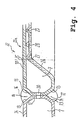
- FIG. 4 is a sectional view similar to the sectional view FIG. 3 shown, wherein the container after FIG. 4 in contrast to the container 1 after the FIGS. 1 to 3 is a double-walled container. Like elements have the same reference numerals.
- the double-walled container after FIG. 4 has similar to the container 1 after the FIGS. 1 to 3 a middle part 22, which is composed of a plurality of ring segments, of which a ring segment in FIG. 4 designated 22a.
- the ring segment 22a adjoins the connection surface 12 at an end portion 24, wherein both the ring member 22 and the end portion 24 each have a chamber 7 is formed circumferentially.
- a chamber 7 is provided in each case, whereby a connection surface 12 and by the bevels 13 welding grooves 14 are formed.
- a welded connection 16 is provided in the inner V-shaped welding groove, and a welded connection 17 is made in the V-shaped groove 14 on the container outer side 11.
- the welded joint 16 seals the Container inside to the pad 12 down and the weld 17 seals the outside 11 to the pad of the container down.
- the ring segment 22 a contains ei ne inner wall 25 and an outer wall 26, wherein in the outer wall formations 27, 28, 29 are formed, which serve as spacers between the inner wall 25 and outer wall 26.
- the spacers 27, 28, 29 formed in the outer wall 26 are at least after the filling of the container at points on the outside of the inner wall 25, wherein a gas located between the inner wall and outer wall can arbitrarily circulate between the spacers 27, 28, 29 and at the spacers 27, 28, 29 can flow past.
- connection surface 12 Between the chamber 7 of the ring member 22a and the chamber 7 of the end portion 24 at least one opening is provided in the connection surface 12 through which gas from the chamber 7 of the ring segment 22a in the chamber 7 of the end piece 24 can flow and vice versa. Also, between the pads of the ring segments with each other and other segments of the container such openings are provided so that a closed interior between the inner walls and the outer walls of all segments is made.
- a negative pressure ie, a vacuum generated in the interior.
- the vacuum warning device monitors an increase in pressure in the interior, and generates a warning message in the event of a pressure increase that indicates a leak.
- the double-walled container can easily be checked for leaks both during manufacture and during use of the container, in particular when storing hazardous substances, a continuous leak test is possible.
- a monitoring of the tightness of the container is ensured in a simple manner.
- Such monitoring which is particularly recommended for the storage of dangerous goods, is by a container according to the invention after Fig. 4 just possible.
- the Spacers can be introduced between the inner wall 25 and the outer wall 26 both in the chamber 7 and in the region of the spacers an open-cell plastic foam or an open-cell foam, which at least allows gas circulation. Through this open-cell plastic foam also monitoring using a Vakuu m-warning device is possible. Alternatively, the bore 30 between the individual segments can be omitted if each segment receives a separate vacuum warning device for monitoring the respective segment cavity.
- both spacers 27, 28, 29 and an open-pored plastic foam between the spacers 27, 28, 29 and in the chamber 7 are provided.
- neither a plastic foam in the cavities of the segments nor spacers 27, 28, 29 are provided.
- these containers have opposite to those in FIG. 4 shown embodiment and compared to a container, in whose cavities an open-cell plastic foam is introduced, a lower stability.
- FIG. 5 is a sectional view of a container portion shown, which has been made of double-walled plastic segments.
- an open-cell plastic foam 32 is introduced, which also serves as a spacer between the inner wall 25 and the outer wall 26 at least in an area outside the chamber 7.
- the open-cell plastic foam 32 as already associated with FIG. 4 also described a gas exchange at least within a segment 22a, 24 possible.
- the chambers 7 of the ring segment 22a and the chamber 7 of the end portion 24 are not connected to each other via an opening.
- the open-cell plastic foam 32 as already associated with FIG. 4 also described a gas exchange at least within a segment 22a, 24 possible.
- the weld 16 and the weld 17 are each designed to be circumferentially sealing in such a way that a gas-tight closed space is created in the area of the connection surfaces 12, each space being defined by the connection surface of the ring segment 22 a, the terminal surface of the end portion 24 and by the welds 16 and 17 is limited.
- a test bore 31 is provided at least at one point, is introduced by a negative pressure in the gas-tight closed space, which is monitored by means of a vacuum warning device. With the aid of this arrangement, both the gas-tightness of the welded joint 16 and the gas-tightness of the welded joint 17 are checked. After checking the test hole 31 is closed gas-tight again.
- Both the inner wall 25 and the outer wall 26 of the container are made of a material with the trade name "Selar", whereby both the inner wall 25 and the outer wall 26 serve as a barrier layer. Permeation in particular of volatile hydrocarbon compounds is thereby effectively prevented.
- the test hole is preferably attached to the outer weld 17. Alternatively, however, the test bore can also be provided on the inner weld joint 16. If the vacuum warning device detects an increase in pressure, an overpressure is then applied via the test bore 31 by introducing gas via the test bore 31 into the closed space between the connecting surfaces 12. Both the circumferential weld 17 and the circumferential weld 16 are wetted by means of a leak spray through which an escaping gas, in particular escaping air, can be easily visualized, whereby the leak / leaks can be easily located.
- openings between the individual cavities of the individual segments of the container present then only a test hole in one of the welds 16, 17 or in an inner or outer wall of the container is required to the tightness of all welds of the double-walled container safely in a test procedure to check.
- the vacuum is then introduced in all areas between the inner wall and the outer wall and penetrates via the opening 30 also in the region of the connection surfaces 12 to the welds 16, 17, so that the tightness the welded joints 16, 17 and in addition the tightness of the inner and outer walls 25, 26 checked at the same time with a scholarbohru ng, ie controlled, can be.
- an overpressure is applied and the pressure drop is detected with the aid of a suitable measuring and evaluation device.
- FIG. 6 is a sectional view of a section of the container wall of a double-walled container shown, which is preferably used for the storage of dangerous goods.
- the inner shell has essentially the same structure as the in FIG. 5 illustrated container.
- the container further has an outer shell 202 which is disposed on the outer wall of the inner shell of the container, wherein between the outer wall of the inner shell and the inner wall of the outer shell, a cavity 200 is formed.
- the inner shell and the outer shell are arranged such that the cavity 2 00 is sealed gas-tight to the environment.
- the gas-tightness of the cavity s 200 is monitored by means of a monitoring device, in particular a vacuum warning device.
- the welds 17 on the outer wall of the inner shell are executed or reworked so that they do not protrude substantially from the outside of the inner shell.
- FIG. 6 shown container Opposite the in FIG. 6 shown container is the double-walled container after FIG. 7 such that the shell 202 forms the inner shell and the shell composed by means of the segments 22a and 24 forms the outer shell of the container. This makes it possible to reduce the mechanical requirements for the inner shell 202.
- Spacers may be provided in the cavity 200 and / or an open-cell plastic foam.
Landscapes
- Engineering & Computer Science (AREA)
- Mechanical Engineering (AREA)
- Physics & Mathematics (AREA)
- General Physics & Mathematics (AREA)
- Lining Or Joining Of Plastics Or The Like (AREA)
- Packages (AREA)
- Cable Accessories (AREA)
- Examining Or Testing Airtightness (AREA)
Description
- Die Erfindung betrifft einen doppelwandigen Behälter, der aus zumindest zwei miteinander verbundenen Segmenten zusammengesetzt ist. Ferner betrifft die Erfindung ein Verfahren zum Überprüfen der Dichtheit eines Behälters zur Aufnahme von vorzugsweise flüssigen Medien. Dieses Verfahren dient zum Überwachen des Behälters, der aus mindestens zwei Segmenten zusammengesetzt ist, die an mindestens einer Stoßstelle miteinander verschweißt sind. Weiterhin betrifft die Erfindung einen Behälter, dessen Innenseite mit einer Barriereschicht überzogen ist, sowie ein Verfahren zum Herstellen eines solchen Behälters.
- Es sind großvolumige Behälter aus Kunststoff bekannt, die aus mehreren Segmenten zusammengesetzt sind. Die Segmente sind vorzugsweise mit Hilfe eines Blasverfahrens hergestellt worden
- Aus der Veröffentlichung der internationalen Patentanmeldung
WO 01/07342 A1 - Nach der Fertigung eines solchen Behälters muss die Dichtheit des Behälters überprüft und je nach Anforderung an den Behälter nachgewiesen werden. Jedoch ist bei Kunststoffbehältern eine Leckage nicht durch einfache Überwachung eines Druckabfalls beim Beaufschlagen des Behälters mit einem Überdruck möglich, da sich ein Kunststoffbehälter, insbesondere ein großvolumiger Kunststoffbehälter bei einer Druckbeaufschlagung weitet, wodurch ein Druckabfall auch ohne Leckage entsteht. Eine Leckage könnte auch durch Ein- bzw. Untertauchen des Behälters in einem flüssigen Medium ermittelt werden, was jedoch insbesondere bei großvolumigen Behältern schwer durchführbar und sehr aufwendig ist. Auch ein Befüllen der Behälter mit einem flüssigen Medium, wie z.B. Wasser, ist sehr aufwendig und schwer in den Produktionsablauf einzugliedern.
- Bei einigen Behältern mit erhöhten Anforderungen an die Dichtheit ist ein Überwachungssystem zum Ermitteln von Undichtigkeiten erforderlich. Behälter mit einer erhöhten Anforderung an die Dichtheit dienen z.B. zur unterirdischen Lagerung von Gefahrgütern. Das Überwachungssystem dient dazu, Leckagen unverzüglich nach ihrem Auftreten zu ermitteln und Maßnahmen zur Schadensminimieru ng einzuleiten. Bei bekannten Behältern erfolgt eine solche Überwachung zumindest bei zweischaligen Behältern mit Hilfe eines so genannten Vakuum-Überwachungsgerätes. Jedoch ist die Herstellung von doppelwandigen blasgeformten Kunststoffbehältern, insbesondere mit einem großen Volumen, nicht mit vertretbarem Aufwand möglich.
- Unterirdische Gefahrgut-Lagerbehälter, z.B. Heizöl-Lagerbehälter, müssen gegen Permeation von leichtflüchtigen Kohlenwasserstoffverbindungen beständig sein. Vor allem bei einer unterirdischen Anordnung des Gefahrgut-Lagerbehälters ist eine solche Beständigkeit erforderlich, um das den Behälter umgebende Erdreich insbesondere nicht mit austretenden Kohlenwasserstoffverbindungen zu kontaminieren. Es ist bekannt, insbesondere Kunststoffbehälter mit einer Permeationssperre zu versehen, wobei die Innenwand des Behälters einem Fluorierungs-Verfahren unterzogen wird. Eine solche Fluorierung erfolgt in Fluorierungskammern, wobei zumindest eine der Behältergröße entsprechende Fluorierungskammer erforderlich ist, um den Behälter zu fluorieren. Dieses ist auch insbesondere bei großvolumigen Behältern > 0,5 m3 Volumen mit einem erheblichen Kostenaufwand verbunden, wobei derzeit keine Fluorierungskammern für Behälter mit mehreren Kubikmetern Volumen zur Verfügung stehen. Eine weitere Möglichkeit besteht darin, die Innenwände einzelner Behältersegmente mit einer so genannten Inline-Fluorierung zu versehen, wobei nur die Innenfläche mit einer Sperrschicht versehen wird. An den Berührungskanten und Schweißnähten ist dann jedoch kein Schutz gegen Permeation gegeben.
- Aus dem Dokument
US-A-4 653 312 ist ein Verfahren bekannt, bei dem ein zum Umgebungsdruck verschiedener Innendruck in einem Zwischenraum zwischen einem Innenbehälter und einem Außenbehälter angelegt wird. Die Druckänderung des Innendrucks wird überwacht. - Aus dem Dokument
EP-A-1 184 157 ist bekannt, einen Behälter aus mindestens zwei Teilen zusammenzusetzen und diese zwei Teile mit Hilfe einer Schweißverbindung zu verbinden. Ferner ist aus diesem Dokument bekannt, auf der Innenseite des Behälters eine Barriereschicht aufzutragen. - Aus dem Dokument
DE 201 07 626 U1 ist bekannt, PTFE-Formkörper dadurch miteinander zu verbinden, dass an ihren Stoßflächen eine mit PTFE schmelzverbundene Schicht aus einem thermoplastischen Fluorpolymer vorgesehen ist. Die verbundenen PTFE-Formkörper dienen insbesondere zum Auskleiden eines Behälters. - Aufgabe der Erfindung ist es, einen Behälter, ein Verfahren zum Herstellen eines Behälters sowie ein Verfahren zum Überwachen der Dichtheit eines Behälters anzugeben, wobei der Behälter einfach und kostengünstig hergestellt werden kann sowie die Dichtheit des Behälters auf einfache Art und Weise ermittelt werden kann.
- Diese Aufgabe wird für ein Verfahren zum Überprüfen der Dichtheit eines Behälters zur Aufnahme von vorzugsweise flüssigen Medien mit den Merkmalen des Patentanspruchs 1 gelöst. Weitere vorteilhafte Ausgestaltungen der Erfindung sind in den Unteransprüchen angegeben.
- Vor allem durch das Vorsehen einer Prüföffnung in der Schweißverbindung kann durch das Überwachen des angelegten zur Umgebung verschiedenen Innendrucks die Dichtheit der Schweißverbindungen durch Überwachung des Druckanstiegs kontrolliert werden. Dadurch wird auf einfache Art und Weise das korrekte Ausführen der Schweißverbindungen und somit die Dichtheit des Behälters überprüft.
- Ein zweiter Aspekt der Erfindung betrifft einen doppelwandigen Behälter, der vorzugsweise zur Lagerung von Gefahrgut dient. Der Behälter ist aus mindestens zwei miteinander verbundenen Segmenten zusammengesetzt. Jedes Segment umfasst ein im Wesentlichen biegesteifes Kunststoffformteil, das eine Innenschale und eine Außenschale hat. Die Innenschale des Kunststoffformteils des Segments ist in einem Abstand zu der Außenschale des Kunststoffformteils derart angeordnet, dass ein Innenraum zwischen den beiden Schalen vorhanden ist. Die ersten und zweiten Kunststoffformteile sind derart miteinander verbunden, dass mindestens ein gasdicht abgeschlossener Innenraum zwischen Innenschale und Außenschale des Behälters vorhanden ist. Ferner ist eine Vorrichtung zum Erzeugen und Überwachen eines vom Umgebungsdruck verschiedenen Innendrucks in den mindestens einen abgeschlossenen Innenraum vorgesehen.
- Dadurch wird bei dem erfindungsgemäßen Behälter die Dichtheit der Innen- und Außenschale durch Überwachen des Innendrucks kontrolliert und/oder überwacht. Bei einer kontinuierlichen Überwachung des Innendrucks können auch Leckagen erkannt werden, die erst bei der Benutzung des Behälters auftreten, wodurch dann unverzüglich Maßnahmen zur Schadensminimierung bzw. zur Schadensverhinderung eingeleitet werden können. Ferner können dadurch Sicherheitsauflagen zur Lagerung von Gefahrgut erfüllt werden.
- Ein dritter Aspekt der Erfindung betrifft ein Verfahren zum Überwachen der Dichtheit eines Behälters, der zur Lagerung von Gefahrgut geeignet ist. Der Behälter wird aus mindestens zwei Segmenten zusammengesetzt, wobei jedes Segment ein im wesentlichen biegesteifes Kunststoffformteil mit einer Innenschale und einer Außenschale enthält. Die Innenschale des Kunststoffformteils eines Segments wird jeweils zur Außenschale desselben Kunststoffformteils in einem Abstand angeordnet. Die Segmente werden derart miteinander verbunden, dass mindestens ein gasdicht abgeschlossenes Innenraum zwischen Innenschale und Außenschale des Behälters erzeugt wird. Ein zum Umgebungsdruck verschiedener Innendruck wird in dem mindestens einen Innenraum angelegt. Eine Änderung des Innendrucks wird überwacht.
- Dadurch wird die Dichtheit des Behälters kontrolliert und beim permanenten Überwachen des Innendrucks kann die Dichtheit des Behälters dauerhaft überwacht werden. Somit können auch nachträglich auftretende Leckagestellen mit relativ geringem Aufwand festgestellt werden.
- Ein vierter Aspekt der Erfindung betrifft einen weiteren Behälter, der vorzugsweise zur Lagerung von Gefahrstoffen dient. Der Behälter ist aus mindestens zwei Segmenten zusammengesetzt, wobei jedes Segment mindestens ein Kunststoffformteil enthält, das mindestens eine Behälterwand umfasst. Ein Teil der inneren Oberfläche des Behälters ist durch die Behälterwände gebildet. Die Behälterwand des ersten Segments und die Behälterwand des zweiten Segments enthalten jeweils eine gasdichte Barriereschicht. Die Behälterwand des ersten und die Behälterwand des zweiten Segments sind durch eine Schweißverbindung miteinander verbunden, wobei in dem beim Schweißen zugeführten Zusatzwerkstoff zumindest ein Anteil eines Barrierematerials für eine gasdichte Barriereschicht enthalten ist. Die Schweißverbindung ist derart ausgeführt, dass die durch die Behälterwände und die Schweißverbindung gebildete Wandung des Behälters eine geschlossene Barriereschicht aufweist.
- Dadurch ist dieser Kunststoffbehälter zur Lagerung von Stoffen geeignet, die eine Barriereschicht an der inneren Wandung des Behälters erfordern, um insbesondere eine Permeation von Stoffen durch die Behälterwand zu verhindern.
- Ein fünfter Aspekt der Erfindung betrifft ein Verfahren zum Herstellen eines Behälters, der vorzugsweise zur Lagerung und zum Transport von Gefahrstoffen dient. Bei dem Verfahren wird der Behälter aus mindestens zwei Segmenten zusammengesetzt, wobei jedes Segment ein Kunststoffformteil enthält, das mindestens eine Behälterwand umfasst. Ein Teil der inneren Oberfläche des Behälters wird durch die Behälterwände gebildet. Durch die Behälterwand des ersten Segments und die Behälterwand des zweiten Segments wird jeweils eine gasdichte Barriereschicht erzeugt. Die Behälterwand des ersten und die Behälterwand des zweiten Segments wird mit Hilfe einer Schweißverbindung verbunden, wobei beim Schweißen ein Zusatzwerkstoff zugeführt wird, der zumindest einen Anteil eines Barrierematerials für eine gasdichte Barriereschicht enthält. Die Schweißverbindung wird derart ausgeführt, dass die Behälterwände mit der Schweißverbindung nach dem Fertigstellen der Schweißverbindung eine geschlossene Barriereschicht aufweisen.
- Durch dieses Verfahren ist es möglich, einen großvolumigen Kunststoffbehälter kostengünstig herzustellen, der auch zur Lagerung und zum Transport von Gefahrstoffen, wie z.B. Heizöl, geeignet ist.
- Ein sechster Aspekt der Erfindung betrifft einen doppelwandigen Behälter vorzugsweise zur Lagerung von Gefahrgut. Der Behälter hat eine erste Schale, die aus mindestens zwei Segmenten zusammengesetzt ist, wobei jedes Segment mindestens ein Kunststoffformteil enthält. Der Behälter hat eine zweite Schale, die derart zu der ersten Schale angeordnet ist, dass zwischen den Schalen ein Raum gasdicht umschlossen ist. Ferner ist eine Vorrichtung zum Überwachen der Gasdichtheit des umschlossenen Raums vorgesehen.
- Ein solcher Behälter ist kostengünstig herzustellen und kann relativ einfach auf Dichtheit geprüft werden.
- Zum besseren Verständnis der vorliegenden Erfindung wird im folgenden auf die in den Zeichnungen dargestellten bevorzugten Ausführungsbeispiele Bezug genommen, die anhand spezifischer Terminologie beschrieben sind. Es sei jedoch darauf hingewiesen, dass der Schutzumfang der Erfindung dadurch nicht eingeschränkt werden soll, da derartige Veränderungen und weitere Modifizierungen an den gezeigten Vorrichtungen und/oder den Verfahren sowie derartige weitere Anwendungen der Erfindung, wie sie darin aufgezweigt sind, als übliches derzeitiges oder künftiges Fachwissen eines zuständigen Fachmannes angesehen werden. Die Figuren zeigen Ausführungsbeispiele der Erfindung, nämlich:
- Figur 1
- eine Seitenansicht eines Kunststoffbehälters;
- Figur 2
- eine Draufsicht des Behälters nach
Figur 1 ; - Figur 3
- eine Schnittdarstellung einer Schweißverbindung zwischen zwei Segmenten des Kunststoffbehälters nach den
Figuren 1 und 2 gemäß einer ersten Ausführungsform der Erfindung; - Figur 4
- eine Schnittdarstellung der Schweißverbindung zwischen zwei Segmenten des Kunststoffbehälters nach den
Figuren 1 und 2 gemäß einer zweiten Ausführungsform der Erfindung; - Figur 5
- eine Schnittdarstellung einer Schweißverbindung zwischen zwei Segmenten des Kunststoffbehälters nach den
Figuren 1 und 2 gemäß einer dritten Ausführungsform der Erfindung; - Figur 6
- einen doppelwandigen Behälter, dessen Außenschale jeweils aus mindestens zwei Segmenten zusammengesetzt ist; und
- Figur 7
- einen doppelwandigen Behälter, dessen Innenschale aus mindestens zwei Segmenten zusammengesetzt ist.
- In den
Figuren 1 und 2 sind Ansichten eines großvolumigen Behälters zur Lagerung von flüssigen Medien, insbesondere von Gefahrstoffen, dargestellt. Jedoch kann ein solcher Behälter auch zur Lagerung von Regenwasser oder anderen ungefährlichen Medien sowie zur Lagerung von insbesondere pulverförmigen Medien genutzt werden. Großvolumige Behälter haben ein Volumen vom mindestens 0,5 m3. Großvolumige Behälter mit mehreren m3 Volumen bis zu mehreren 10 m3 Volumen werden auch als Tank bezeichnet. - Der Kunststoffbehälter 1 hat ein zylinderförmiges hohles Mittelteil 2, das an seinen beiden Stirnseiten 3 mit jeweils einem Endteil 4 verbunden ist, wodurch die Endteile 3 und das Mittelteil 2 einen geschlossenen Behälter 1 bilden. Das Mittelteil 2 ist aus drei Ringsegmenten 2a, 2b, 2c zusammengesetzt, wobei sowohl die Ringsegmente 2a, 2b, 2c als auch die beiden Endteile 4 mit Hilfe von Schweißverbindungen derart fest miteinander verbunden sind, dass ein geschlossener, dichter Behälter 1 erzeugt wird. Die drei Ringsegmente 2a, 2b, 2c und die zwei Endteile 4 enthalten Versteifungsrippen 5, die im wesentlichen den gleichen Querschnitt haben. Die Länge der Versteifungsrippen 5 kann jedoch je nach Position der Versteifungsrippe 5 am Behälter 1 und den statischen Anforderungen an den Behälter 1 unterschiedlich lang ausgebildet sein. An dem oberen Ringsegment 2c des Mittelteils ist eine Einfüll- und Entleerungsöffnung 6 angeformt. Die Versteifungsrippen 5 sind an den äußeren Wandflächen angeordnet, wodurch die Innenseite des Behälters 1 eine im wesentlichen glatte Oberfläche hat. Durch die Versteifungsrippen 5 wird einer Verformung des Behälters 1 beim Befüllen und durch äußere Krafteinwirkung, z.B. nach dem Einbringen des Behälters 1 ins Erdreich, verhindert. Die glatte Behälterinnenseite ermöglicht ein leichtes Entleeren sowie eine einfache Reinigung des Behälters 1.
- In
Figur 3 sind zwei aneinander stoßende Versteifungsrippen 5 dargestellt, die an den Rändern aneinander stoßender Segmente 2 und 4 des Behälters 1 ausgebildet sind. Die Versteifungsrippen 5 enthalten Kammern 7, die bei der Herstellung der Ringsegmente 2a, 2b, 2c und der Endteile 4 im so genannten Blasverfahren einstückig mit dem jeweiligen Segment 2a, 2b, 2c bzw. mit dem Endteil 4 hergestellt worden sind. Zur Herstellung der Ringsegmente 2a, 2b, 2c und der Endteile 4 im Blasformverfahren wird auf die bereits erwähnte internationale PatentanmeldungWO 01/07342 A1 - Das Ringsegment 2a und das Endteil 4 sind mit Hilfe einer inneren Schweißverbindung 16 und einer äußeren Schweißverbindung 17 fest miteinander verbunden, wobei zumindest die Schweißung 16 als durchgehende Schweißnaht ausgeführt ist und dadurch eine dichte Verbindung zwischen dem Ringsegment 2a und dem Endteil 4 besteht. Das Endteil 4 und das Ringsegment 2a haben jeweils eine innenwand 10 und eine Außenwand 11. An den aneinander stoßenden Kanten der Versteifungsrippen 5 des Endteils 4 und des Ringsegments 2a sind Schrägen vorgesehen, die beim Aneinanderstoßen des Endteils 4 an das Ringsegment 2a jeweils an der Innenseite 10 und der Außenseite 11 eine V-förmige Schweißnut 14 bilden. Die Schrägen haben in
Figur 3 das Bezugszeichen 13. - Das Endteil 4 und das Ringsegment 2a haben jeweils eine Anschlussfläche 12, die beim Aneinanderfügen des Endteils 4 an das Ringsegment 2a aneinander liegen. An die Anschlussfläche 12 schließt sich jeweils nach innen und außen eine bereits beschriebene Schräge 13 an, die dann als Schweißnut 14 dient. Die Schrägen 13 der Schweißnut 14 haben einen Winkel im Bereich von 15 bis 45°. Vorzugsweise hat die innere Wandung 10 eine größere Wandstärke als die äußere Wandung 11. Ferner ist in der Außenwand 11 eine Öffnung 15 vorgesehen, die beim bereits erwähnten Blasverfahren als Einbringöffnung für die beim Blasverfahren erforderliche Luft bzw. ein erforderliches Gas dient und die später auch zum Einbringen anderer Stoffe, wie z.B. Beton oder Schaum in die Kammer 7 genutzt werden kann.
- Der Behälter 1 wird als unterirdischer Gefahrgut-Lagerbehälter genutzt. Unterirdische Gefahrgut-Lagerbehälter müssen derart ausgeführt sine, dass keine Permeation von leicht flüchtigen Kohlenwasserstoffverbindungen möglich ist. Insbesondere bei Druckunterschieden zwischen Innenbehälter und dem umgebenden Erdreich ist bei Kunststoffbehältern die Gefahr von Permeation gegeben. Bei einer Permeation, d.h. Durchdringung der Behälterwand, von leicht flüchtigen Kohlenwasserstoffverbindungen würden diese in die Umgebung des Behälters 1 abgegeben werden, wodurch diese kontaminiert wird. Es ist bekannt, Kunststoffbehälter mit Hilfe eines Fluorierungs-Verfahrens mit einer Permeationssperre zu versehen. Aufgrund der vorliegenden Behältergröße des Behälters 1 ist jedoch eine Fluorierung des gesamten Behälters wirtschaftlich nicht vertretbar, da die Fluorierung des Behälters in einer so genannten "Fluorierungskammer" durchgeführt werden muss, die derzeit nicht in Abmessungen vorhanden sind, die für derartige Behältergrößen geeignet sind.
- Eine weitere Möglichkeit, die innere Oberfläche des Behälters 1 mit Hilfe eines Fluorierungs-Verfahrens zu behandeln, besteht durch eine so genannte Inline-Fluorierung der einzelnen Behältersegmente 2a, 2b, 2c, 4. Bei der Inline-Fluorierung wird eine Barriereschicht zumindest an der Innenseite der Innenwand 10 der Behältersegmente 2a, 2b, 2c, 4 erzeugt. An den Verbindungsstellen der Segmente, d.h. insbesondere an der Schweißnaht 16 ist jedoch dann keine Barriereschicht vorhanden. Erfindungsgemäß wird beim Herstellen der Schweißverbindung 16 ein Zusatzwerkstoff zugeführt, der zumindest einen Anteil eines Barrierematerials enthält. Die Schweißverbindung 16 ist dabei derart ausgeführt, dass die innere Oberfläche 10 des Behälters 1 nach dem Schweißen eine geschlossene Barriereschicht aufweist. Die einzelnen Behältersegmente 2a, 2b, 2c, 4 werden einzeln im Offline-Verfahren fluoriert. Anschließend wird die bei der Fluorierung erzeugte Barriereschicht an den Schweißnahtflächen, d.h. an den Schrägen 13, abgeschliffen. Die Schweißverbindung 16, 17 zwischen den einzelnen Segmenten 2a, 2b, 2c, 4 wird mit Hilfe eines Schmelz-Schweiß-Verfahrens hergestellt, wobei der zugeführte Zusatzwerkstoff, d.h. das zugeführte Schmelzmaterial, aus einem Materialgemisch besteht, das einen Anteil eines Barrierematerials enthält. So ein Barrierematerial wird z.B. unter dem Markennamen "Selar" von der Firma Du Pont vertrieben. Der übrige Bestandteil des Zusatzwerkstoffs ist ein übliche beim Schmelz-Schweiß-Verfahren verwendeter Zusatzwerkstoff, vorzugsweise der gleiche Kunststoff, aus dem die Segmente 2a, 2b, 2c, 4 bestehen.
- Das Ausbilden einer geschlossenen Barriereschicht, die zuvor für den einschichtigen Behälter 1 beschrieben worden ist, kann auch bei Behältern angewendet werden , bei denen die einzelnen Segmente mehrschichtig sind. Bei diesen Behältern ist zumindest eine der Schicht, vorzugsweise die Behälterinnenseite, als Barriereschicht ausgebildet.
- In
Figur 4 ist eine Schnittdarstellung ähnlich der Schnittdarstellung nachFigur 3 dargestellt, wobei der Behälter nachFigur 4 im Unterschied zu dem Behälter 1 nach denFiguren 1 bis 3 ein doppelwandiger Behälter ist. Gleiche Elemente haben gleiche Bezugszeichen. Der doppelwandige Behälter nachFigur 4 hat ähnlich dem Behälter 1 nach denFiguren 1 bis 3 ein Mittelteil 22, das aus mehreren Ringsegmenten zusammengesetzt ist, von denen ein Ringsegment inFigur 4 mit 22a bezeichnet ist. Das Ringsegment 22a grenzt an der Anschlussfläche 12 an ein Endteil 24, wobei sowohl am Ringelement 22 als auch am Endteil 24 jeweils eine Kammer 7 umlaufend ausgebildet ist. Zumindest an den Verbindungsstellen der Ringsegmente untereinander und der Ringsegmente mit den Endteilen 24 ist jeweils eine Kammer 7 vorgesehen, wodurch eine Anschlussfläche 12 sowie durch die Schrägen 13 Schweißnuten 14 gebildet sind. Von der Behälterinnenseite 10 her ist eine Schweißverbindung 16 in der inneren V-förmigen Schweißnut vorgesehen und an der Behälteraußenseite 11 ist eine Schweißverbindung 17 in der V-förmigen Nut 14 eingebracht. Die Schweißverbindung 16 dichtet das den Behälter innen zur Anschlussfläche 12 hin ab und die Schweißnaht 17 dichtet die Außenseite 11 zur Anschlussfläche des Behälters hin ab. - Im Unterschied zur Anordnung nach
Figur 3 ist die dort dargestellte Blasöffnung 15 bei dem Behälter nachFigur 4 gasdicht verschlossen worden. Das Ringsegment 22a enthält ei ne Innenwand 25 und eine Außenwand 26, wobei in der Außenwand Ausformungen 27, 28, 29 gebildet sind, die als Abstandshalter zwischen Innenwand 25 und Außenwand 26 dienen. Die in der Außenwand 26 gebildeten Abstandshalter 27, 28, 29 liegen zumindest nach dem Befüllen des Behälters punktuell an der Außenseite der Innenwand 25 an, wobei ein zwischen Innenwand und Außenwand befindliches Gas beliebig zwischen den Abstandshaltern 27, 28, 29 zirkulieren kann bzw. an den Abstandshaltern 27, 28, 29 vorbeiströmen kann. Zwischen der Kammer 7 des Ringelements 22a und der Kammer 7 des Endteils 24 ist in der Anschlussfläche 12 mindestens eine Öffnung vorgesehen, durch die Gas aus der Kammer 7 des Ringsegments 22a in die Kammer 7 des Endstücks 24 strömen kann und umgekehrt. Auch zwischen den Anschlussflächen der Ringsegmente untereinander und weiteren Segmenten des Behälters sind derartige Öffnungen vorgesehen, so dass ein geschlossener Innenraum zwischen den Innenwänden und den Außenwänden aller Segmente hergestellt ist. - Mit Hilfe eines Vakuum-Warngerätes, das mit diesem geschlossenen Innenraum aller Segmente 22a, 24 verbunden ist, wird im Innenraum ein Unterdruck, d.h. ein Vakuum, erzeugt. Das Vakuum-Warngerät überwacht einen Druckanstieg im innenraum, und erzeugt bei einem Druckanstieg, der auf eine Leckage schließen lässt, eine Warnmeldung. Dadurch kann der doppelwandige Behälter sowohl bei der Herstellung einfach auf Dichtheit überprüft werden, als auch während einer Benutzung des Behälters insbesondere bei der Lagerung von Gefahrstoffen, ist eine kontinuierliche Dichtheitsprüfung möglich. Dadurch ist eine Überwachung der Dichtheit des Behälters ist auf einfache Art und Weise gewährleistet. Eine solche Überwachung, die insbesondere bei der Lagerung von Gefahrgütern empfohlen ist, ist durch einen erfindungsgemäßen Behälter nach
Fig. 4 einfach möglich. Wird bei dieser Überprüfung eine Undichtigkeit des Behälters festgestellt, können sofort Maßnahmen zur Schadensminimierung durchgeführt werden. Alternativ zu den Abstandshaltern kann zwischen der Innenwand 25 und der Außenwand 26 sowohl in der Kammer 7 als auch im Bereich der Abstandshalter ein offenzelliger Kunststoffschaum bzw. ein offenzelliger Schaumstoff eingebracht werden, der eine Gaszirkulation zumindest zulässt. Durch diesen offenzelligen Kunststoffschaum ist auch eine Überwachung mit Hilfe eines Vakuu m-Warngerätes möglich. Alternativ kann auf die Bohrung 30 zwischen den einzelnen Segmenten verzichtet werden, wenn jedes Segment ein separates Vakuum-Warngerät zum Überwachen des jeweiligen Segmenthohlraums erhält. - Bei anderen Ausführungsbeispielen sind sowohl Abstandshalter 27, 28, 29 als auch ein offenporiger Kunststoffschaum zwischen den Abstandshaltern 27, 28, 29 und in der Kammer 7 vorgesehen. Bei alternativen Ausführungsbeispielen ist weder ein Kunststoffschaum in den Hohlräumen der Segmente noch sind Abstandshalter 27, 28, 29 vorgesehen. Jedoch haben diese Behälter gegenüber der in
Figur 4 gezeigten Ausführungsform und gegenüber einem Behälter, in dessen Hohlräumen ein offenporiger Kunststoffschaum eingebracht ist, eine geringere Stabilität. - In
Figur 5 ist eine Schnittdarstellung eines Behälterabschnitts gezeigt, der aus doppelwandigen Kunststoffsegmenten hergestellt worden ist. Bei dem Behälter nachFigur 5 ist anstatt der Abstandshalter 27, 28, 29 zwischen der Innenwand 27 und der Außenwand 26 ein offenzelliger Kunststoffschaum 32 eingebracht, der zumindest in einem Bereich außerhalb der Kammer 7 auch als Abstandshalter zwischen der innenwand 25 und der Außenwand 26 dient. Ferner ist durch den offenzelligen Kunststoffschaum 32, wie bereits im Zusammenhang mitFigur 4 beschrieben, auch ein Gasaustausch zumindest innerhalb eines Segments 22a, 24 möglich. Im Unterschied zu dem Behälter n achFigur 4 sind die Kammern 7 des Ringsegments 22a und die Kammer 7 des Endteils 24 nicht über eine Öffnung miteinander verbunden. Jedoch ist auch bei dem Behälter nachFigur 5 die Schweißung 16 und die Schweißung 17 jeweils derart umlaufend dichtend ausgeführt, dass im Bereich der Anschlussflächen 12 ein gasdicht abgeschlossener Raum entsteht, der jeweils von der Anschlussfläche des Ringsegments 22a, von der Anschlussfläche des Endteils 24 sowie durch die Schweißungen 16 und 17 begrenzt ist. - In der Schweißnaht 17 ist zumindest an einer Stelle eine Prüfbohrung 31 vorgesehen, durch die ein Unterdruck in den gasdicht abgeschlossenen Raum eingebracht wird, der mit Hilfe eines Vakuum-Warngeräts überwacht ist. Mit Hilfe dieser Anordnung wird sowohl die Gasdichtheit der Schweißverbindung 16 als auch die Gasdichtheit der Schweißverbindung 17 überprüft. Nach der Überprüfung wird die Prüfbohrung 31 wieder gasdicht verschlossen.
- Sowohl die Innenwand 25 als auch die Außenwand 26 des Behälters sind aus einem Werkstoff mit der Handelsbezeichnung "Selar" hergestellt, wodurch sowohl die Innenwand 25 als auch die Außenwand 26 als Barriereschicht dienen. Eine Permeation insbesondere von leicht flüchtigen Kohlenwasserstoffverbindungen wird dadurch wirkungsvoll verhindert. Die Prüfbohrung wird vorzugsweise an der äußeren Schweißverbindung 17 angebracht. Alternativ kann die Prüfbohrung jedoch auch an der inneren Schweißverbindung 16 vorgesehen werden. Erfasst das Vakuum-Warngerät einen Druckanstieg, wird anschließend über die Prüfbohrung 31 ein Überdruck angelegt, indem Gas über die Prüfbohrung 31 in den abgeschlossenen Raum zwischen den Anschlussflächen 12 eingebracht wird. Sowohl die umlaufende Schweißnaht 17 als auch die umlaufende Schweißnaht 16 werden mit Hilfe eines Lecksprays benetzt, durch das ein austretendes Gas, insbesondere austretende Luft, sehr einfach sichtbar gemacht werden kann, wodurch die Leckstelle / die Leckstellen leicht lokalisiert wird/werden können.
- Alternativ sind, wie in
Figur 4 gezeigt, Öffnungen zwischen den einzelnen Hohlräumen der einzelnen Segmente des Behälters vorhanden, wobei dann nur eine Prüfbohrung in einer der Schweißnähte 16, 17 oder in einer Innen- oder Außenwand des Behälters erforderlich ist, um die Dichtheit aller Schweißnähte des doppelwandigen Behälters sicher in einem Prüfvorgang zu überprüfen. In diesem Fall wird das Vakuum dann in allen Bereichen zwischen der Innenwand und der Außenwand eingebracht und dringt über die Öffnung 30 auch in den Bereich der Anschlussflächen 12 bis zu den Schweißnähten 16, 17 vor, so dass die Dichtheit der Schweißverbindungen 16, 17 und zusätzlich die Dichtheit der Innen- und Außenwände 25, 26 gleichzeitig mit der einen Prüfbohru ng überprüft, d.h. kontrolliert, werden kann. Alternativ wird bei anderen Ausführungsbeispielen anstatt des Unterdrucks ein Überdruck angelegt und der Druckabfall mit Hilfe einer geeigneten Mess- und Auswertevorrichtung erfasst. - In
Figur 6 ist eine Schnittdarstellung eines Ausschnitts der Behälterwand eines doppelwandigen Behälters dargestellt, der vorzugsweise zur Lagerung von Gefahrgut genutzt wird. Die Innenschale hat dabei im wesentlichen den gleichen Aufbau, wie der inFigur 5 dargestellte Behälter. Der Behälter hat ferner eine Außenschale 202, die an der Außenwand der Innenschale des Behälters angeordnet ist, wobei zwischen der Außenwand der Innenschale und der Innenwand der Außenschale ein Hohlraum 200 gebildet wird. Die Innenschale und die Außenschale sind derart angeordnet, dass der Hohlraum 2 00 gasdicht zur Umgebung abgeschlossen ist. Die Gasdichtheit des Hohlraum s 200 wird mit Hilfe einer Überwachungsvorrichtung, insbesondere einem Vakuum-Warngerät, überwacht. Die Schweißnähte 17 an der Außenwand der Innenschale sind derart ausgeführt bzw. nachbearbeitet, dass sie im wesentlichen nicht aus der Außenseite der Innenschale hervorstehen. - Gegenüber dem in
Figur 6 dargestellten Behälter ist der doppelwandige Behälter nachFigur 7 derart aufgebaut, dass die Schale 202 die Innenschale und die mit Hilfe der Segmente 22a und 24 zusammengesetzte Schale die Außenschale des Behälters bildet. Dadurch ist es möglich, die mechanischen Anforderungen an die Innenschale 202 zu verringern. - Auch bei den Behältern nach
Figur 6 undFigur 7 können Abstandshalter im Hohlraum 200 und/oder ein offenporiger Kunststoffschaum vorgesehen sein. - Obgleich in den Zeichnungen und in der vorhergehende n Beschreibung bevorzugte Ausführungsbeispiele aufgezeigt und detailliert besch rieben worden sind, soll sie lediglich als rein beispielhaft und die Erfindung nicht einschränkend angesehen werden. Es wird darauf hingewiesen, dass nur die bevorzugten Ausführungsbeispiele dargestellt und beschrieben sind und sämtliche Veränderungen und Modifizierungen, die derzeit und künftig im Schutzumfang der Erfindung liegen, geschützt werden sollen.
-
- 1
- Behälter
- 2, 22
- Mittelteil
- 2a, 2b, 2c, 22a
- Ringsegmente
- 4, 24
- Endteile
- 5
- Versteifungsrippen
- 6
- Befüll- und Entleerungsöffnung
- 7
- Kammer
- 10,25
- Innenwand
- 11, 26
- Außenwand
- 12
- Anschlussfläche
- 13
- Schrägen
- 14
- V-förmige Nut
- 15
- Blasöffnung
- 16, 17
- Schweißnaht
- 27, 28, 29
- Abstandshalter
- 30
- Öffnung
- 31
- Prüfbohrung
- 32
- offenporiger Kunststoffschaum
- 100,200
- Zwischenraum
- 202
- Schale
Claims (14)
- Verfahren zum Überprüfen der Dichtheit eines Behälters zur Aufnahme von Medien,
bei dem der Behälter (1) aus mindestens zwei Segmenten (2a, 4) zusammengesetzt wird, die an den Rändern ihrer Stirnflächen umlaufend mit je einer Schweißverbindung (16, 17) derart verbunden werden, dass ein abgeschlossener Raum zwischen den Stirnflächen gebildet wird, der von der Schweißverbindung und zumindest einem Bereich der Stirnflächen umschlossen wird,
in dem abgeschlossenen Raum ein zum Umgebungsdruck verschiedener Innendruck angelegt wird,
und bei dem eine Druckänderung des Innendrucks überwacht wird. - Verfahren nach Anspruch 1, dadurch gekennzeichnet, dass der abgeschlossene Raum ein ringförmiger Raum ist, der sich um den Behälterquerschnitt herum erstreckt
- Verfahren nach einem der vorhergehenden Ansprüche, dadurch gekennzeichnet, dass der Innendruck über eine Öffnung (31), insbesondere eine Bohrung, eingebracht und/oder überwacht wird.
- Verfahren nach einem der vorhergehenden Ansprüche, dadurch gekennzeichnet, dass als Innendruck ein Unterdruck gegenüber dem Umgebungsdruck angelegt wird, und dass eine Druckdifferenz des Innendrucks zum Umgebungsdruck überwacht wird.
- Verfahren nach Anspruch 4, dadurch gekennzeichnet, dass bei einer Änderung der Druckdifferenz, die auf eine Leckage schließen lässt, über die Öffnung (31) ein Überdruck angelegt wird, wobei ein Gas zum Erzeugen eines Überdrucks eingebracht wird,
und dass ein Mittel im Bereich der Schweißverbindung aufgebracht wird, durch dass die Leckagestelle bei einem Gasaustritt sichtbar gemacht wird. - Verfahren nach Anspruch 5, dadurch gekennzeichnet, dass als Mittel ein Leckspray aufgebracht wird.
- Verfahren nach einem der vorhergehenden Ansprüche, dadurch gekennzeichnet, dass die, Segmente (2a, 4) des Behälters (1) aus einem Kunststoffmaterial hergestellt sind.
- Verfahren nach einem der vorhergehenden Ansprüche, dadurch gekennzeichnet, dass mindestens ein Segment (2a, 4) im Blasformverfahren hergestellt wird.
- Verfahren nach einem der vorhergehenden Ansprüche, dadurch gekennzeichnet, dass der Behälter (1) mindestens zwei schalenartige Endsegmente (4) mit jeweils einer ringförmigen ebenen Anschlussfläche als Stirnfläche enthält, und
dass der Behälter (1) mindestens ein im wesentlichen zylinderförmiges Mittelsegment (2) mit ebenfalls ringförmigen, ebenen Anschlussflächen als Stirnflächen enthält, wobei die Anschlussflächen des Mittelsegments (2) im wesentlichen mit der Anschlussfläche eines der Endsegmente (4) deckungsgleich sind. - Verfahren nach Anspruch 8, dadurch gekennzeichnet, dass das Mittelsegment eine Befüll- und Entleerungsöffnung (6), vorzugsweise einen Dom, enthält.
- Verfahren nach Anspruch 8 oder 9, dadurch gekennzeichnet, dass zumindest das Mittelteil mit als Kammern (7) ausgebildete Versteifungsrippen (5) versehen ist, wobei zumindest eine Kammer (7) an eine Stirnseite angrenzt, die die Anschlussfläche (12) enthält.
- Verfahren nach einem der vorhergehenden Ansprüche, dadurch gekennzeichnet, dass jedes der Segmente (2a, 4) im Bereich ihrer Anschlussflächen mindestens eine umlaufende Kammer (7) hat, und dass
die Anschlussflächen (12) an ihren umlaufenden Begrenzungskanten in zurücklaufende Schrägen (13) zur Bildung von Schweißnuten (14) zwischen den Segmenten (2a, 4) übergehen. - Verfahren nach Anspruch 12, dadurch gekennzeichnet, dass die Schrägen (13) unter einem Winkel von etwa 10° bis 45° verlaufen.
- Verfahren nach einem der vorhergehenden Ansprüche, dadurch gekennzeichnet, dass die Öffnung (31) in einer außen am Behälter liegende Schweißnaht (17) eingebracht wird.
Applications Claiming Priority (2)
| Application Number | Priority Date | Filing Date | Title |
|---|---|---|---|
| DE200410017535 DE102004017535A1 (de) | 2004-04-08 | 2004-04-08 | Behälter zur Aufnahme von Medien sowie Verfahren zur Herstellung und zum Überprüfen der Dichtheit des Behälters |
| PCT/EP2005/003675 WO2005098390A2 (de) | 2004-04-08 | 2005-04-07 | Behälter zur aufnahme von medien sowie verfahren zur herstellung und zum überprüfen der dichtheit des behälters |
Publications (2)
| Publication Number | Publication Date |
|---|---|
| EP1737765A2 EP1737765A2 (de) | 2007-01-03 |
| EP1737765B1 true EP1737765B1 (de) | 2009-09-02 |
Family
ID=34965938
Family Applications (1)
| Application Number | Title | Priority Date | Filing Date |
|---|---|---|---|
| EP05736532A Not-in-force EP1737765B1 (de) | 2004-04-08 | 2005-04-07 | Behälter zur aufnahme von medien sowie verfahren zur herstellung und zum überprüfen der dichtheit des behälters |
Country Status (5)
| Country | Link |
|---|---|
| US (1) | US8096168B2 (de) |
| EP (1) | EP1737765B1 (de) |
| AT (1) | ATE441605T1 (de) |
| DE (2) | DE102004017535A1 (de) |
| WO (1) | WO2005098390A2 (de) |
Families Citing this family (9)
| Publication number | Priority date | Publication date | Assignee | Title |
|---|---|---|---|---|
| EP2374735B1 (de) * | 2010-04-12 | 2013-06-12 | Graf Plastics GmbH | Tank |
| DE202012103630U1 (de) * | 2012-09-21 | 2014-01-02 | Bodo Richter | Lagertank zum Aufnehmen von Flüssigkeiten |
| EP2969909B1 (de) * | 2013-03-14 | 2017-06-28 | Miroslav Zerdik | Mobile betankungsstation |
| DE102013103714B4 (de) * | 2013-04-12 | 2016-08-04 | Deutsches Zentrum für Luft- und Raumfahrt e.V. | Einrichtung und verfahren zum bereitstellen eines wärmekontaktes von einem gasspeicher auf einen kühlkörper |
| DE102013021287A1 (de) * | 2013-12-19 | 2015-06-25 | Stiebel Eltron Gmbh & Co. Kg | Fügebauteil zum Aufnehmen und/oder Führen eines Fluids |
| US10696448B1 (en) | 2016-01-22 | 2020-06-30 | Infiltrator Water Technologies Llc | Making a plastic tank with an integrity-verifiable weld joint |
| CN106500915A (zh) * | 2016-10-31 | 2017-03-15 | 哈尔滨电机厂有限责任公司 | 气密焊接结构的气密性测试方法 |
| CN108827542A (zh) * | 2018-03-15 | 2018-11-16 | 五冶集团上海有限公司 | 一种补强板焊缝检测方法 |
| DE102019107015B3 (de) * | 2019-03-19 | 2020-06-18 | Andreas Schmitt | Verfahren zur Prüfung der Dichtheit von einer Plattenrigole |
Family Cites Families (13)
| Publication number | Priority date | Publication date | Assignee | Title |
|---|---|---|---|---|
| FR1423402A (fr) * | 1964-04-06 | 1966-01-03 | Usines Ragheno Ancien Etabliss | Réservoir |
| BE795542A (fr) * | 1972-02-18 | 1973-06-18 | Dynamit Nobel Ag | Procede et dispositif pour controler sous vide l'etancheite des cordons de soudure des bandes en matiere plastique |
| US4653312A (en) * | 1983-10-21 | 1987-03-31 | Sharp Bruce R | Storage tanks having formed rigid jacket for secondary containment |
| US5170660A (en) * | 1987-10-28 | 1992-12-15 | Martin Lehmann | Process and apparatus for volume-testing a hollow body |
| DE3750043D1 (de) * | 1987-10-28 | 1994-07-14 | Martin Lehmann | Verfahren und Verwendung einer Anordnung zur Prüfung mindestens eines Hohlkörpers auf sein Volumenverhalten. |
| US5102481A (en) * | 1988-07-05 | 1992-04-07 | Sharp Bruce R | Method of building double walled fibrous reinforced resinous storage tanks with common rib supports |
| US5333491A (en) * | 1989-01-27 | 1994-08-02 | Martin Lehmann | Method for reducing test cycle time and for improving measuring accuracy at a leak testing process |
| AU635035B2 (en) | 1989-05-16 | 1993-03-11 | J.M. Huber Corporation | Endothermic blowing agents compositions and applications |
| US5054645A (en) * | 1990-05-02 | 1991-10-08 | Sharp Bruce R | Storage tank systems with enhanced strength having in situ formed inner tank |
| DE29912902U1 (de) | 1999-07-23 | 1999-11-18 | Richter Guenter | Großvolumiger Behälter zur Aufnahme von flüssigen Medien |
| DE10042121A1 (de) * | 2000-08-28 | 2002-03-14 | Basell Polyolefine Gmbh | Verfahren zur Herstellung von Kunststoffhohlkörpern |
| DE20107626U1 (de) * | 2001-05-04 | 2001-08-02 | Michel Wolfgang | Mit Fluorpolymeren verbundene Polytetrafluorethylen-Formkörper |
| US6886389B1 (en) * | 2003-12-10 | 2005-05-03 | The Boeing Company | Systems and methods for detecting and locating leaks in internal pressure vessels |
-
2004
- 2004-04-08 DE DE200410017535 patent/DE102004017535A1/de not_active Withdrawn
-
2005
- 2005-04-07 DE DE502005008049T patent/DE502005008049D1/de active Active
- 2005-04-07 WO PCT/EP2005/003675 patent/WO2005098390A2/de active Application Filing
- 2005-04-07 EP EP05736532A patent/EP1737765B1/de not_active Not-in-force
- 2005-04-07 AT AT05736532T patent/ATE441605T1/de not_active IP Right Cessation
- 2005-04-07 US US11/547,931 patent/US8096168B2/en not_active Expired - Fee Related
Also Published As
| Publication number | Publication date |
|---|---|
| US20090018381A1 (en) | 2009-01-15 |
| DE502005008049D1 (de) | 2009-10-15 |
| EP1737765A2 (de) | 2007-01-03 |
| WO2005098390A2 (de) | 2005-10-20 |
| US8096168B2 (en) | 2012-01-17 |
| WO2005098390A3 (de) | 2005-12-22 |
| DE102004017535A1 (de) | 2005-10-27 |
| ATE441605T1 (de) | 2009-09-15 |
Similar Documents
| Publication | Publication Date | Title |
|---|---|---|
| EP1737765B1 (de) | Behälter zur aufnahme von medien sowie verfahren zur herstellung und zum überprüfen der dichtheit des behälters | |
| EP3256656B1 (de) | Wiederverwendbare schutzvorrichtung gegen wasserfortleitung | |
| DE4236338C2 (de) | Faßdeckel | |
| EP2990711B1 (de) | Gehäuseanordnung für eine rohrverbindung sowie verfahren zum schutz von rohrverbindungen | |
| EP2603728B1 (de) | System zur abdichtung eines rohrleitungssystems | |
| DE3844045A1 (de) | Rohrverbindung | |
| DE19815679A1 (de) | Dichtungsvorrichtung für Rohrleitungen | |
| EP3500833B1 (de) | Verfahren zum überprüfen einer dichtheit eines flexiblen behälters | |
| EP3032146A1 (de) | Dichtungselement | |
| EP3146156B1 (de) | Schutzelement zum verbinden mit einem betonelement eines tunnelausbaus mit drainage | |
| EP2921643A1 (de) | Schutzelement, Betonelement und Verfahren zur Herstellung eines Betonelements | |
| CH614417A5 (en) | Method for producing a leak-proofing lining on an existing, single-walled steel tank, and tank produced according to the method | |
| DE3816066A1 (de) | Mehrwandiger, aus einer mehrzahl von bauelementen zusammensetzbarer lagerbehaelter und wand-bauelement zum aufbau solcher lagerbehaelter | |
| DE1243375B (de) | In das Erdreich einzubettender Lagerbehaelter | |
| DE4139565C2 (de) | Flüssigkeitsdichte Auskleidung von Kanalrohren | |
| EP0989946B1 (de) | Unterirdischer, mehrschichtiger behälter hergestellt durch rotationsverfahren | |
| DE102012022537B4 (de) | Verschlussanordnung für insbesondere aus Faserverbundwerkstoff hergestellte Behälter | |
| EP0511343A1 (de) | Vorrichtung zum überwachen der dichtheit von im freien und im erdreich verlegten rohren und rohrleitungen und bauwerken aus thermoplastischem kunststoff. | |
| DE10004695C1 (de) | Dichtsystem an einem Konstruktionselement mit einer verschliessbaren Durchlassöffnung und Verfahren zur Anwendung | |
| DE102019116131A1 (de) | Kreuzrollenlager | |
| DE4119125C1 (de) | ||
| EP3591166B1 (de) | Tunnelausbau zusammengesetzt aus wenigstens zwei betonelementen | |
| DE102021002321B3 (de) | Tank, insbesondere großvolumiger Erdtank | |
| EP1382438A1 (de) | Kunststoffrohr | |
| DE2843174A1 (de) | Doppelwandiger lagerbehaelter fuer fluessigkeiten, insbesondere fuer heizoel, sowie verfahren zu seiner herstellung |
Legal Events
| Date | Code | Title | Description |
|---|---|---|---|
| PUAI | Public reference made under article 153(3) epc to a published international application that has entered the european phase |
Free format text: ORIGINAL CODE: 0009012 |
|
| 17P | Request for examination filed |
Effective date: 20061106 |
|
| AK | Designated contracting states |
Kind code of ref document: A2 Designated state(s): AT BE BG CH CY CZ DE DK EE ES FI FR GB GR HU IE IS IT LI LT LU MC NL PL PT RO SE SI SK TR |
|
| 17Q | First examination report despatched |
Effective date: 20070207 |
|
| DAX | Request for extension of the european patent (deleted) | ||
| GRAP | Despatch of communication of intention to grant a patent |
Free format text: ORIGINAL CODE: EPIDOSNIGR1 |
|
| GRAS | Grant fee paid |
Free format text: ORIGINAL CODE: EPIDOSNIGR3 |
|
| GRAA | (expected) grant |
Free format text: ORIGINAL CODE: 0009210 |
|
| AK | Designated contracting states |
Kind code of ref document: B1 Designated state(s): AT BE BG CH CY CZ DE DK EE ES FI FR GB GR HU IE IS IT LI LT LU MC NL PL PT RO SE SI SK TR |
|
| REG | Reference to a national code |
Ref country code: CH Ref legal event code: EP |
|
| REG | Reference to a national code |
Ref country code: IE Ref legal event code: FG4D Free format text: LANGUAGE OF EP DOCUMENT: GERMAN |
|
| REF | Corresponds to: |
Ref document number: 502005008049 Country of ref document: DE Date of ref document: 20091015 Kind code of ref document: P |
|
| PG25 | Lapsed in a contracting state [announced via postgrant information from national office to epo] |
Ref country code: FI Free format text: LAPSE BECAUSE OF FAILURE TO SUBMIT A TRANSLATION OF THE DESCRIPTION OR TO PAY THE FEE WITHIN THE PRESCRIBED TIME-LIMIT Effective date: 20090902 Ref country code: SE Free format text: LAPSE BECAUSE OF FAILURE TO SUBMIT A TRANSLATION OF THE DESCRIPTION OR TO PAY THE FEE WITHIN THE PRESCRIBED TIME-LIMIT Effective date: 20090902 Ref country code: LT Free format text: LAPSE BECAUSE OF FAILURE TO SUBMIT A TRANSLATION OF THE DESCRIPTION OR TO PAY THE FEE WITHIN THE PRESCRIBED TIME-LIMIT Effective date: 20090902 |
|
| NLV1 | Nl: lapsed or annulled due to failure to fulfill the requirements of art. 29p and 29m of the patents act | ||
| LTIE | Lt: invalidation of european patent or patent extension |
Effective date: 20090902 |
|
| PG25 | Lapsed in a contracting state [announced via postgrant information from national office to epo] |
Ref country code: SI Free format text: LAPSE BECAUSE OF FAILURE TO SUBMIT A TRANSLATION OF THE DESCRIPTION OR TO PAY THE FEE WITHIN THE PRESCRIBED TIME-LIMIT Effective date: 20090902 Ref country code: PL Free format text: LAPSE BECAUSE OF FAILURE TO SUBMIT A TRANSLATION OF THE DESCRIPTION OR TO PAY THE FEE WITHIN THE PRESCRIBED TIME-LIMIT Effective date: 20090902 Ref country code: NL Free format text: LAPSE BECAUSE OF FAILURE TO SUBMIT A TRANSLATION OF THE DESCRIPTION OR TO PAY THE FEE WITHIN THE PRESCRIBED TIME-LIMIT Effective date: 20090902 |
|
| PG25 | Lapsed in a contracting state [announced via postgrant information from national office to epo] |
Ref country code: CY Free format text: LAPSE BECAUSE OF FAILURE TO SUBMIT A TRANSLATION OF THE DESCRIPTION OR TO PAY THE FEE WITHIN THE PRESCRIBED TIME-LIMIT Effective date: 20090902 |
|
| REG | Reference to a national code |
Ref country code: IE Ref legal event code: FD4D |
|
| PG25 | Lapsed in a contracting state [announced via postgrant information from national office to epo] |
Ref country code: PT Free format text: LAPSE BECAUSE OF FAILURE TO SUBMIT A TRANSLATION OF THE DESCRIPTION OR TO PAY THE FEE WITHIN THE PRESCRIBED TIME-LIMIT Effective date: 20100104 Ref country code: RO Free format text: LAPSE BECAUSE OF FAILURE TO SUBMIT A TRANSLATION OF THE DESCRIPTION OR TO PAY THE FEE WITHIN THE PRESCRIBED TIME-LIMIT Effective date: 20090902 Ref country code: CZ Free format text: LAPSE BECAUSE OF FAILURE TO SUBMIT A TRANSLATION OF THE DESCRIPTION OR TO PAY THE FEE WITHIN THE PRESCRIBED TIME-LIMIT Effective date: 20090902 Ref country code: IE Free format text: LAPSE BECAUSE OF FAILURE TO SUBMIT A TRANSLATION OF THE DESCRIPTION OR TO PAY THE FEE WITHIN THE PRESCRIBED TIME-LIMIT Effective date: 20090902 Ref country code: ES Free format text: LAPSE BECAUSE OF FAILURE TO SUBMIT A TRANSLATION OF THE DESCRIPTION OR TO PAY THE FEE WITHIN THE PRESCRIBED TIME-LIMIT Effective date: 20091213 Ref country code: EE Free format text: LAPSE BECAUSE OF FAILURE TO SUBMIT A TRANSLATION OF THE DESCRIPTION OR TO PAY THE FEE WITHIN THE PRESCRIBED TIME-LIMIT Effective date: 20090902 Ref country code: IS Free format text: LAPSE BECAUSE OF FAILURE TO SUBMIT A TRANSLATION OF THE DESCRIPTION OR TO PAY THE FEE WITHIN THE PRESCRIBED TIME-LIMIT Effective date: 20100102 |
|
| PG25 | Lapsed in a contracting state [announced via postgrant information from national office to epo] |
Ref country code: SK Free format text: LAPSE BECAUSE OF FAILURE TO SUBMIT A TRANSLATION OF THE DESCRIPTION OR TO PAY THE FEE WITHIN THE PRESCRIBED TIME-LIMIT Effective date: 20090902 |
|
| PLBE | No opposition filed within time limit |
Free format text: ORIGINAL CODE: 0009261 |
|
| STAA | Information on the status of an ep patent application or granted ep patent |
Free format text: STATUS: NO OPPOSITION FILED WITHIN TIME LIMIT |
|
| PG25 | Lapsed in a contracting state [announced via postgrant information from national office to epo] |
Ref country code: DK Free format text: LAPSE BECAUSE OF FAILURE TO SUBMIT A TRANSLATION OF THE DESCRIPTION OR TO PAY THE FEE WITHIN THE PRESCRIBED TIME-LIMIT Effective date: 20090902 |
|
| 26N | No opposition filed |
Effective date: 20100603 |
|
| PG25 | Lapsed in a contracting state [announced via postgrant information from national office to epo] |
Ref country code: GR Free format text: LAPSE BECAUSE OF FAILURE TO SUBMIT A TRANSLATION OF THE DESCRIPTION OR TO PAY THE FEE WITHIN THE PRESCRIBED TIME-LIMIT Effective date: 20091203 |
|
| BERE | Be: lapsed |
Owner name: RICHTER, GUNTER Effective date: 20100430 |
|
| PG25 | Lapsed in a contracting state [announced via postgrant information from national office to epo] |
Ref country code: MC Free format text: LAPSE BECAUSE OF NON-PAYMENT OF DUE FEES Effective date: 20100430 |
|
| REG | Reference to a national code |
Ref country code: CH Ref legal event code: PL |
|
| PG25 | Lapsed in a contracting state [announced via postgrant information from national office to epo] |
Ref country code: CH Free format text: LAPSE BECAUSE OF NON-PAYMENT OF DUE FEES Effective date: 20100430 Ref country code: LI Free format text: LAPSE BECAUSE OF NON-PAYMENT OF DUE FEES Effective date: 20100430 |
|
| PG25 | Lapsed in a contracting state [announced via postgrant information from national office to epo] |
Ref country code: BE Free format text: LAPSE BECAUSE OF NON-PAYMENT OF DUE FEES Effective date: 20100430 |
|
| PG25 | Lapsed in a contracting state [announced via postgrant information from national office to epo] |
Ref country code: AT Free format text: LAPSE BECAUSE OF NON-PAYMENT OF DUE FEES Effective date: 20100407 |
|
| PG25 | Lapsed in a contracting state [announced via postgrant information from national office to epo] |
Ref country code: HU Free format text: LAPSE BECAUSE OF FAILURE TO SUBMIT A TRANSLATION OF THE DESCRIPTION OR TO PAY THE FEE WITHIN THE PRESCRIBED TIME-LIMIT Effective date: 20100303 Ref country code: BG Free format text: LAPSE BECAUSE OF FAILURE TO SUBMIT A TRANSLATION OF THE DESCRIPTION OR TO PAY THE FEE WITHIN THE PRESCRIBED TIME-LIMIT Effective date: 20090902 Ref country code: LU Free format text: LAPSE BECAUSE OF NON-PAYMENT OF DUE FEES Effective date: 20100407 |
|
| REG | Reference to a national code |
Ref country code: DE Ref legal event code: R082 Ref document number: 502005008049 Country of ref document: DE Representative=s name: SCHAUMBURG & PARTNER PATENTANWAELTE GBR, DE Ref country code: DE Ref legal event code: R082 Ref document number: 502005008049 Country of ref document: DE Representative=s name: SCHAUMBURG UND PARTNER PATENTANWAELTE MBB, DE |
|
| REG | Reference to a national code |
Ref country code: FR Ref legal event code: PLFP Year of fee payment: 12 |
|
| REG | Reference to a national code |
Ref country code: FR Ref legal event code: PLFP Year of fee payment: 13 |
|
| REG | Reference to a national code |
Ref country code: FR Ref legal event code: PLFP Year of fee payment: 14 |
|
| PGFP | Annual fee paid to national office [announced via postgrant information from national office to epo] |
Ref country code: TR Payment date: 20180328 Year of fee payment: 14 |
|
| PGFP | Annual fee paid to national office [announced via postgrant information from national office to epo] |
Ref country code: DE Payment date: 20180529 Year of fee payment: 14 |
|
| PGFP | Annual fee paid to national office [announced via postgrant information from national office to epo] |
Ref country code: FR Payment date: 20180424 Year of fee payment: 14 Ref country code: IT Payment date: 20180420 Year of fee payment: 14 |
|
| PGFP | Annual fee paid to national office [announced via postgrant information from national office to epo] |
Ref country code: GB Payment date: 20180403 Year of fee payment: 14 |
|
| REG | Reference to a national code |
Ref country code: DE Ref legal event code: R119 Ref document number: 502005008049 Country of ref document: DE |
|
| GBPC | Gb: european patent ceased through non-payment of renewal fee |
Effective date: 20190407 |
|
| PG25 | Lapsed in a contracting state [announced via postgrant information from national office to epo] |
Ref country code: DE Free format text: LAPSE BECAUSE OF NON-PAYMENT OF DUE FEES Effective date: 20191101 Ref country code: GB Free format text: LAPSE BECAUSE OF NON-PAYMENT OF DUE FEES Effective date: 20190407 |
|
| PG25 | Lapsed in a contracting state [announced via postgrant information from national office to epo] |
Ref country code: FR Free format text: LAPSE BECAUSE OF NON-PAYMENT OF DUE FEES Effective date: 20190430 |
|
| PG25 | Lapsed in a contracting state [announced via postgrant information from national office to epo] |
Ref country code: IT Free format text: LAPSE BECAUSE OF NON-PAYMENT OF DUE FEES Effective date: 20190407 |
|
| PG25 | Lapsed in a contracting state [announced via postgrant information from national office to epo] |
Ref country code: TR Free format text: LAPSE BECAUSE OF NON-PAYMENT OF DUE FEES Effective date: 20190407 |