EP1737101B1 - Rotary electric machine and manufacturing method thereof - Google Patents
Rotary electric machine and manufacturing method thereof Download PDFInfo
- Publication number
- EP1737101B1 EP1737101B1 EP06020315A EP06020315A EP1737101B1 EP 1737101 B1 EP1737101 B1 EP 1737101B1 EP 06020315 A EP06020315 A EP 06020315A EP 06020315 A EP06020315 A EP 06020315A EP 1737101 B1 EP1737101 B1 EP 1737101B1
- Authority
- EP
- European Patent Office
- Prior art keywords
- stator core
- curve
- insert
- stator
- portions
- Prior art date
- Legal status (The legal status is an assumption and is not a legal conclusion. Google has not performed a legal analysis and makes no representation as to the accuracy of the status listed.)
- Expired - Fee Related
Links
Images


Classifications
-
- H—ELECTRICITY
- H02—GENERATION; CONVERSION OR DISTRIBUTION OF ELECTRIC POWER
- H02K—DYNAMO-ELECTRIC MACHINES
- H02K15/00—Methods or apparatus specially adapted for manufacturing, assembling, maintaining or repairing of dynamo-electric machines
- H02K15/04—Methods or apparatus specially adapted for manufacturing, assembling, maintaining or repairing of dynamo-electric machines of windings, prior to mounting into machines
- H02K15/0414—Windings consisting of separate elements, e.g. bars, hairpins, segments, half coils
- H02K15/0421—Windings consisting of separate elements, e.g. bars, hairpins, segments, half coils consisting of single conductors, e.g. hairpins
-
- H—ELECTRICITY
- H02—GENERATION; CONVERSION OR DISTRIBUTION OF ELECTRIC POWER
- H02K—DYNAMO-ELECTRIC MACHINES
- H02K3/00—Details of windings
- H02K3/04—Windings characterised by the conductor shape, form or construction, e.g. with bar conductors
- H02K3/12—Windings characterised by the conductor shape, form or construction, e.g. with bar conductors arranged in slots
Definitions
- the present invention relates to a rotary electric machine and its manufacturing method.
- a stator has a stator coil that is constructed of a plurality of U-shaped conductor segments. The segments are inserted into slots of a stator core from an axial end of the stator core and the ends of the segments are connected on the opposite axial end of the stator core. With this stator, a compact, efficient, and low cost alternator is provided.
- an insulation gap between legs of U-shaped conductor segment in a turn portion is larger than that of the insert portions of the U-shaped segment, which is located in the slot, in order to improve insulation in the turn portion.
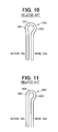
- a segment 500 having its original shape shown in Fig. 10 is used as the U-shaped segment of the stator coil.
- a turn portion 502 has a small curve portion 504, which is arranged adjacent to an outer diameter of the stator core in the slot, and a large curve portion 506, which is arranged adjacent to an inner diameter of the stator core in the slot.
- the inside diameter of the coil end is smaller than the outside diameter of a rotor, thereby improving insulation in the turn portion.
- the segment 600 is curved in a turn portion 602 such that a curve portion 606 that is arranged adjacent to the inner diameter of the stator core is curved and a portion 604 that is arranged adjacent to the outer diameter of the stator core is substantially flat.
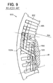
- Fig. 9 shows a part of a stator 900 in which large segments 1331 and small segments 1332 are inserted in slots 905 of a stator core 902.
- An angle 11 formed between the longitudinal centerline of the slot 905 coincident with a radius of the stator core 902 and the centerline of the large segment 1331 is approximately 110 deg..
- An angle 12 formed between the longitudinal centerline of the slot 905 coincident with a radius of the stator core 902 and the centerline of the large segment 1331 is approximately 90 deg..
- the angle 11 is larger than the angle 12.
- the turn portion 1331c is more curved on the inside of the stator core than the outside of the stator core.
- the smallest inside diameter R1 of the coil end is smaller than the inside diameter Rso of the stator core 902.
- multi-phase coil windings are inserted in a stator core and only the coil windings in one of the phases are curved toward an outer periphery of the stator core in a turn portion. Since only the coil windings in one of the phases are curved, the lengths of the coil windings and those of the coil windings in other phases are different. In other words, the resistances of the coil windings are different. As a result, the power generation performance decreases.
- EP 1 005 137 discloses a stator of a vehicle AC generator including a stator core, a multi-phase stator winding formed from a plurality of conductor members.
- the stator winding has coil-ends at opposite sides of said stator core, and portions of the conductor members in each of the coil-ends are radially aligned to have fixed radial clearances therebetween for introducing cooling air and ensuring insulation of the conductor members.
- the present invention therefore has an objective to provide a rotary electric machine that is advanced in size, power output, and cost, while power generation performance, low fan noise, and ease of production are maintained.
- the present invention has another objective to provide a manufacturing method for manufacturing the rotary electric machine.
- the objectives of the present invention are solved by the feature combination according to claim 1 and claim 13. Further advantageous developments and embodiments are subject to depended claims 2 to 12 and 14 to 16.
- a rotary electric machine that includes a rotor, a stator located radially outside the rotor, and a housing enclosing the rotor and the stator.
- the stator includes a stator core with a plurality of slots in its inner periphery, and a stator coil passing through the slots.
- the stator coil has insert portions located in the slots and connecting portions connecting the insert portions axially outside of the stator core.
- Each of the connecting portions has a first curve portion and a second curve portion.
- the first curve portion is located adjacent to an outer diameter of the stator core and the second curve portion is located adjacent to an inside diameter of the stator core.
- the first curve portion has a curvature larger than that of the second curve portion.
- the stator coil is constructed of U-shaped wires.
- the U-shaped wire is manufactured by cutting a longitudinal wire into a predetermined length, bending the wire into a substantially U-shape, and forming a first curve portion in a curved portion of the U-shape.
- the first curve portion is formed on a side which is arranged adjacent to the outer diameter of the stator core. Then, the U-shape wire is twisted in a predetermined shape prior to an installation in the slot.
- the manufacturing process of the rotary electric machine is simplified. Further, manufacturing costs of the same can be reduced.
- a vehicular alternator 1 shown in Fig. 1 is a three-phase generator and driven by an engine (not shown).
- the left side and the right side of the alternator 1 in FIG. 1 are referred to as a front end a rear end, respectively.
- the alternator 1 includes a stator 2, a rotor 3, a housing 4, and a rectifier 5.
- the rotor 3 rotates with a shaft 6, and functions as a field magnet.
- the rotor 3 includes a Lundell-type pole core 7, a field coil 8, slip rings 9, 10, a mixed flow fan 11, and a centrifugal fan 12.
- the shaft 6 is connected to a pulley 20, and rotated by the engine (not shown).
- the Lundell-type pole core 7 is constructed of a pair of pole cores. Each pole core includes a boss portion 71 fixed around the shaft 6 and a disc portion 72, which extends from the axial end of the boss portion 71 in the radial direction. Also, the pole core 7 includes sixteen claw poles 73. The field coil 8 is wound around the boss portions 71.
- the mixed flow fan 11 includes a base plate 111, inclined blades that are arranged at acute angles to the base plate 111 and right-angled blades that are arranged at right angles to the base plate 111.
- the base plate 111 is fixed to a front end surface of the pole core 7 by welding or other method, so that the mixed flow fan 11 rotates with the rotor 3.
- the centrifugal fan 12 includes a base plate 121, and blades that are arranged at right angles to the base plate 121.
- the base plate 121 is fixed to the rear end surface of the pole core 7 by welding or other method, so that the centrifugal fan 12 rotates with the rotor 3.
- the stator 2 functions as an armature.
- the stator 2 is located to surround the outer periphery of the rotor 3.
- the stator 2 includes a stator core 32 and a multi-phase stator coil 31.
- the stator coil 31 is constructed of a plurality of electric conductors.
- the electric conductors are arranged in slots 35 formed in the inner periphery of the stator core 32.
- the stator coil 31 protrudes from the rear and front ends of the stator core 32 in the axial direction and forms a first coil end 31a and a second coil end 31b.
- the housing 4 is constructed of a front housing 4a and a rear housing 4b.
- the housing 4 has air inlet holes 41 on its front and rear end surfaces.
- the housing 4 also has air outlet holes 42 in the portions opposed to the first coil end 31 a and the second coil end 31b.
- the front housing 4a has a step 4f on its inner periphery.
- the front housing 4a and the rear housing 4b are fastened with a stud bolt (fixing member) 4c such that the stator 2 and rotor 3 are held by the front and rear housings 4a and 4b.
- a stud bolt (fixing member) 4c such that the stator 2 and rotor 3 are held by the front and rear housings 4a and 4b.
- the axial front end of the stator core 32 is in press-contact with the step 4f by being pressed with a flange 4f of the stud bolt 4c in the axial direction, so that the stator core 32 is sandwiched between the step 4f and the flange 4g.
- the rectifier 5 is fixed to the end of the rear housing 4b and opposed to the first coil end 31a.
- the rectifier 5 rectifies an AC voltage outputted from the stator 2 to a DC voltage.
- stator 2 is described in detail.
- the stator core 32 has evenly spaced slots 35 opening radially inward of the stator core 32.
- the electric conductors of the stator coil 31 are arranged in the slots 35 through insulators 34.
- the insulators 34 provide electric insulation between the stator core 32 and the stator coil 31.
- the number of slots 35 is determined based on the number of poles of the rotor 3 and the number of the phases of the stator coil 31. In this embodiment, seventy-two slots are formed, for example.
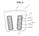
- Fig. 3 shows shapes of the electric conductor installed in the slots 35 of the stator core 32.
- the electric conductors 331, 332 are provided by shaping or twisting substantially U-shaped wires into predetermined shapes. Each conductor has substantially rectangular cross-section in even thickness.
- the conductors 331, 332 are arranged in a predetermined pattern to construct the stator coil 31.
- even-numbered electric conductors e.g. four conductors in this embodiment
- straight portions (insert portions) 331a, 332a, 332b, 331b of the conductors 331, 332 are arranged in line, forming the inner layer (first layer), the inner middle layer (second layer), the outer middle layer (third layer), and the outer layer (fourth layer) in the radially outward direction of the stator core 32.
- the first coil end 31a is constructed of connecting portions (turn portions) 331c, 332c of the conductors 331, 332 axially outside the stator core 32.
- the second coil end 31b is constructed by connecting ends 331d, 331e, 332d, 332e of conductors 331, 332 axially outside the stator core 32.
- One conductor of one layer in a slot 35 pairs up with one conductor of another layer in a slot 35 that is in one pole pitch next to the slot 35 to maintain spaces between the conductors and to arrange the conductors orderly.
- the insert portion 331a of the first layer pairs up with the insert portion 331b of the fourth layer in the slot 35 that is one pole pitch next to that the insert portion 331a passes.
- the insert portion 332a of the second layer pairs up with the insert portion 332b of the third layer in the slot 35 that is one pole pitch next to that the insert portion 332a passes.
- the insert portions 331a, 332a are connected to the insert portions 331b, 332b through the connecting portions 331c, 332c, respectively, at the axially outside the axial rear end of the stator core 32.
- the connecting portions 331c form outer layer coil ends and the turn portions 332c form middle layer coil ends.
- the outer layer coil ends and middle layer coil ends form the first coil end 31a.
- the insert portion 332a of the second layer also pairs up with the insert portion 331a' of the first layer in the slot 35 that is one pole pitch next to that the insert portion 332a passes.
- the insert portion 331b' of the fourth layer pairs up with the insert portion 332b of the third layer in the slot 35 that is one pole pitch next to that the insert portion 331b' passes.
- the end 332d of the insert portion 332a is connected to the end 331d' of the insert portion 331a' at the axially outside the axial front end of the stator core 32.
- the end 331e' of the insert portion 331b' is connected to the end 332e of the insert portion 332b at the axially outside the axial front end of the stator core 32.
- the connecting portion of the ends 331d' and 332d and the connecting portion of the ends 332e and 331e' are arranged in the radial direction of the stator core 32, so that adjacent layer coil ends are formed. In this way, the connecting portions of the conductor ends are arranged without overlapping at the axially outside the axial front end of the stator core 32, so that the second coil end 31b is formed.
- the conductor 331 including the insert portions 331a, 331b, connecting portion 331c and ends 331d, 331e is referred to as a large segment.
- the conductor 332 including the insert portions 332a, 332b, connecting portion 332c and ends 332d, 332e is referred to as a small segment.
- the large segments 331 and the small segments 332 are included in base segments 33.
- the base segments 33 are arranged in the slots 35 in specific patterns so that the stator coil 31 turning twice around the stator core 32 is formed.
- the segments forming lead-out wires of the stator coil 31 and turn portions connecting the first and second laps of the stator coil 31 are included in special shape segments.
- the stator coil 31 includes nine special shape segments.
- the special shaped coil end is formed by connecting the first lap and the second lap, that is, by connecting the inner layer coil end and the outer layer coil end.
- the base segments 33 are arranged such that the turn portions 331c of the large segments 331 pass outside the turn portions 332c of the small segments 332.
- the segments 33 are twisted so that the insert portion 331a and the insert portion 332a respectively correspond to be in the first layer and second layer in the slot (first slot) 35, and the conductor 332b and the conductor 331b respectively correspond to be in the third layer and the fourth layer in another slot (second slot) 35 that is one pole pitch from the first slot in the clockwise direction of the stator core 32.
- the twisted segments 33 are inserted into the slots 35 from the axial rear end of the stator core 32.
- the insert portions 331a, 331b, 332a, and 332b are arranged in the slots 35 in the manner described above.
- the ends of the segments 33 which protrude from the axial front end of the stator core 32, are bent. Specifically, the ends 331d and 331e of the large segments 331 are bent as the ends 331d become away from the ends 331e in the circumferential direction of the stator core 32. Each of the ends 331d, 331e of the large segments 331 reaches the point roughly one and a half slots away from the slot 35 that the segment 331 passes. The ends 332d and 332e of the small segments 332 are bent as the ends 332d become close to the end 332e. Each of the ends 332d, 332e reaches the point roughly one and a half slots away.
- the end 331e' of the fourth layer and the end 332e of the third layer are electrically connected by welding such as ultrasonic welding, arc welding, and brazing.
- the end 332d of the second layer and the end 331d' of the first layer are electrically connected.
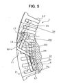
- An angle ⁇ 1 formed between the longitudinal centerline L1 of the slot 35 coincident with a radius of the stator core 32 and the centerline L2 of the segment 331 extending from the first layer is approximately 90 deg..
- An angle 2 formed between the longitudinal centerline L3 of the slot 35 coincident with a radius of the stator core 32 and the centerline L4 of the segment 331 extending from the fourth layer is approximately 100 deg.. That is, the angle 2 is larger than the angle 1.
- a curve adjacent to the inner diameter of the stator core 32 is smaller than a curve adjacent to the outer diameter of the stator core 32.
- the smallest inside diameter D1 of the first coil end 31 a is larger than the inside diameter Dso of the stator core 32.
- the turn portion 331c is folded, at a part adjacent to the inner diameter of the stator core 32, toward the outer diameter side of the stator core 32 with respect to an inside diameter contact line of the slot 35.
- the small segments 332 are arranged in the same manner.
- the smallest inside diameter D1 is larger than the outside diameter Dr of the rotor 3.
- the largest outside diameter D2 of the base segment 33 that is, the outer diameter of the first coil end 31a is larger than the outside diameter Ds of the stator core 32. This reduces interference in the coil ends 31a with the other components. Thus, the height of the coil ends can be reduced. This also reduces the fan noise because a space between the fan and the coil ends 31a is increased.
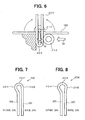
- the U-shaped wires for providing the segments 331, 332 are manufactured as shown in Fig 6 .
- a longitudinal wire is cut in a certain length to provide a straight wire 100 (step 1).
- the straight wire 100 is placed in a specified position, and bent substantially into a U-shape by moving a movable pin 210 downward (shown by an arrow A1) (step 2).
- a U-shaped wire 200 having a turn portion 202, a first straight portion 205, and a second straight portion 207 is made.
- a shaping roller 212 is moved in the horizontal direction (shown by an arrow A2), so that one side of the turn portion 202 is dented to form the curve portion (large curve portion) 204 (step 3), as shown in Fig. 7 .
- the turn portion 202 has a flattered portion 206 on a side opposite to the large curve portion 204.
- the large curve portion 204 is referred to as a first curve portion and the flattered portion 206 is referred to as a second curve portion.
- the turn portion 202 corresponds to the turn portion (connecting portion) 331c, 332c.
- the wires 200 are placed as the segments 33 such that the first curve portion 204 is to be adjacent to the outer diameter of the stator core 32 and the second curve portion 206 is to be adjacent to the inner diameter of the stator core 32 (adjacent to the rotor 3). Then, the wires 200 are twisted into the predetermined shape as described above and inserted in the slots 35, so the segments 33 are arranged as shown in FIG. 5 .
- a part of the first straight portion 205 corresponds to the insert portions 331b, 332b which are located in the slot 35 adjacent to the outer diameter of the stator core 32.
- a part of the second straight portion 207 corresponds to the insert portions 331a, 332a which are located in the slot 35 adjacent to the inner diameter of the stator core 32.
- the turn portions 331c, 332c of the segments 331, 332 have the large curve portions 204 on the outer diameter side of the stator core 32 and the flat portions 206 on the inner diameter side, evenness of an inner periphery of the first coil ends 31a improves. With this, the spaces between the coil ends 31a, 31b and the cooling air generating means, such as the mixed flow fan 11 and the centrifugal fan 12 are widened. Therefore, the fan noise is reduced.
- curves can be uniformly formed for all segments 33 other than the specific shaped segments.
- the segments 33 are produced in the same length (same resistance). As a result, power generation performance can be maintained.
- the largest outside diameter D2 of the first coil end 31a is larger than the outside diameter Ds of the stator core 32.
- the inner diameter of the rear housing 4b, which faces the first coil end 31a is larger than that of the front housing 4a.
- the rear housing 4b has the air holes 42 at a position facing the first coil end 31a. Therefore, the cooling performance is improved.
- the segment 33 has substantially rectangular shaped cross-sections at least at insert portions, so that the area of the slot 35 occupied by the segments 33 increases. Therefore, high power output can be gained while the size is reduced.
- the cooling efficiency can be improved at the coil ends 31a because the air passages in the centrifugal direction increases, as compared with segments having circular-shaped cross-sections in the same cross-sectional areas.
- stator 2 can be easier and reduced in cost by using the U-shaped wire 200 to form the stator coil 31.
- present invention should not be limited to the embodiment previously discussed and shown in the figures, but may be implemented in various ways falling within the terms of the claims.
- the second curve portion 206 may be slightly curved, as shown in Fig. 8 .
- a U-shaped wire 200A has the small curve portion 208 on a side arranged to be adjacent to the inner diameter of the stator core 32, and the large curve portion 204 on a side arranged adjacent to the outer diameter side of the stator core 32.
- the curvature of the first curve portion 204 is larger than that of the second curve portion 208.
- two shaping rollers 212 are used in the step 3.
- the first curve portion 204 and the second curve portion 208 are formed by applying forces with the two rollers 212 from both sides of the wire 200A.
- the present invention can be applied to any kind of rotor electric devices other than the one for vehicular power generators.
Landscapes
- Engineering & Computer Science (AREA)
- Power Engineering (AREA)
- Manufacturing & Machinery (AREA)
- Windings For Motors And Generators (AREA)
- Manufacture Of Motors, Generators (AREA)
- Insulation, Fastening Of Motor, Generator Windings (AREA)
- Synchronous Machinery (AREA)
Applications Claiming Priority (2)
| Application Number | Priority Date | Filing Date | Title |
|---|---|---|---|
| JP2001368683A JP3741037B2 (ja) | 2001-12-03 | 2001-12-03 | 回転電機およびその製造方法 |
| EP02026794A EP1317047B1 (en) | 2001-12-03 | 2002-12-02 | Rotary electric machine and manufacturing method thereof |
Related Parent Applications (2)
| Application Number | Title | Priority Date | Filing Date |
|---|---|---|---|
| EP02026794A Division EP1317047B1 (en) | 2001-12-03 | 2002-12-02 | Rotary electric machine and manufacturing method thereof |
| EP02026794.4 Division | 2002-12-02 |
Publications (2)
| Publication Number | Publication Date |
|---|---|
| EP1737101A1 EP1737101A1 (en) | 2006-12-27 |
| EP1737101B1 true EP1737101B1 (en) | 2011-06-29 |
Family
ID=19178233
Family Applications (2)
| Application Number | Title | Priority Date | Filing Date |
|---|---|---|---|
| EP06020315A Expired - Fee Related EP1737101B1 (en) | 2001-12-03 | 2002-12-02 | Rotary electric machine and manufacturing method thereof |
| EP02026794A Expired - Fee Related EP1317047B1 (en) | 2001-12-03 | 2002-12-02 | Rotary electric machine and manufacturing method thereof |
Family Applications After (1)
| Application Number | Title | Priority Date | Filing Date |
|---|---|---|---|
| EP02026794A Expired - Fee Related EP1317047B1 (en) | 2001-12-03 | 2002-12-02 | Rotary electric machine and manufacturing method thereof |
Country Status (4)
| Country | Link |
|---|---|
| US (1) | US6762528B2 (ja) |
| EP (2) | EP1737101B1 (ja) |
| JP (1) | JP3741037B2 (ja) |
| DE (1) | DE60218608T2 (ja) |
Families Citing this family (16)
| Publication number | Priority date | Publication date | Assignee | Title |
|---|---|---|---|---|
| JP3775349B2 (ja) * | 2002-06-03 | 2006-05-17 | 株式会社デンソー | 回転電機の固定子巻線の製造方法、巻線構造および巻線の製造方法 |
| JP2006149049A (ja) * | 2004-11-18 | 2006-06-08 | Denso Corp | 車両用回転電機 |
| US7911106B2 (en) * | 2007-03-29 | 2011-03-22 | Hitachi, Ltd. | Rotary electric machine |
| JP2009100590A (ja) * | 2007-10-18 | 2009-05-07 | Denso Corp | 車両用交流発電機およびその搭載方法 |
| JP4831125B2 (ja) * | 2008-05-21 | 2011-12-07 | トヨタ自動車株式会社 | 巻線方法、巻線装置、及び固定子 |
| JP5453913B2 (ja) * | 2009-05-13 | 2014-03-26 | 日産自動車株式会社 | 回転電機 |
| JP5278546B2 (ja) * | 2009-12-18 | 2013-09-04 | トヨタ自動車株式会社 | ステータ |
| WO2011128919A1 (en) * | 2010-04-14 | 2011-10-20 | Tecnomatic S.P.A. | Apparatus and method for pre-forming electrical bar conductors, in particular for bar windings of electrical machines |
| JP5751176B2 (ja) * | 2012-01-18 | 2015-07-22 | 株式会社デンソー | 車両用回転電機の固定子 |
| JP5850878B2 (ja) * | 2013-05-16 | 2016-02-03 | 本田技研工業株式会社 | セグメントコンダクタ型の回転電機のステータ及びその製造方法 |
| JP6299723B2 (ja) * | 2015-10-23 | 2018-03-28 | トヨタ自動車株式会社 | ステータコイル形成方法 |
| TWI622249B (zh) | 2016-11-25 | 2018-04-21 | 台達電子工業股份有限公司 | 定子 |
| DE102017004538A1 (de) | 2017-05-11 | 2018-11-15 | Gehring E-Tech Gmbh | Verfahren und Vorrichtung zum Umformen von U-förmigen elektrischen Leitern |
| JP6634431B2 (ja) * | 2017-12-26 | 2020-01-22 | 本田技研工業株式会社 | 回転電機のステータ |
| CN112491225B (zh) * | 2019-09-11 | 2024-03-01 | 博世汽车部件(苏州)有限公司 | 用于电导线的成形和嵌入装置和方法及定子制造设备 |
| DE102022207428A1 (de) | 2022-07-21 | 2024-02-01 | Zf Friedrichshafen Ag | Anordnung für eine elektrische Maschine und Rotor oder Stator für eine elektrische Maschine |
Family Cites Families (10)
| Publication number | Priority date | Publication date | Assignee | Title |
|---|---|---|---|---|
| JP3509302B2 (ja) | 1995-06-27 | 2004-03-22 | 株式会社デンソー | 車両用発電機 |
| WO1998054822A1 (fr) | 1997-05-26 | 1998-12-03 | Denso Corporation | Alternateur pour vehicule |
| WO1999021267A1 (fr) * | 1997-10-16 | 1999-04-29 | Denso Corporation | Procede et dispositif permettant de fabriquer un stator d'alternateur pour vehicule |
| JP3285534B2 (ja) * | 1998-04-08 | 2002-05-27 | 三菱電機株式会社 | 車両用交流発電機の固定子 |
| JP2000037132A (ja) | 1998-07-22 | 2000-02-08 | Iseki & Co Ltd | コンバインの排穀操作装置 |
| JP3427748B2 (ja) * | 1998-10-09 | 2003-07-22 | 株式会社デンソー | 車両用交流発電機 |
| JP3250533B2 (ja) * | 1998-11-25 | 2002-01-28 | 株式会社デンソー | 車両用交流発電機の固定子及びその製造方法 |
| JP3407676B2 (ja) * | 1998-11-26 | 2003-05-19 | 株式会社デンソー | 車両用交流発電機の固定子およびそれを用いた車両用交流発電機 |
| JP4114282B2 (ja) | 1999-07-15 | 2008-07-09 | 株式会社デンソー | 回転電機およびその製造方法 |
| JP2001231203A (ja) * | 2000-02-10 | 2001-08-24 | Mitsubishi Electric Corp | 車両用交流発電機 |
-
2001
- 2001-12-03 JP JP2001368683A patent/JP3741037B2/ja not_active Expired - Fee Related
-
2002
- 2002-12-02 EP EP06020315A patent/EP1737101B1/en not_active Expired - Fee Related
- 2002-12-02 US US10/307,305 patent/US6762528B2/en not_active Expired - Lifetime
- 2002-12-02 EP EP02026794A patent/EP1317047B1/en not_active Expired - Fee Related
- 2002-12-02 DE DE60218608T patent/DE60218608T2/de not_active Expired - Lifetime
Also Published As
| Publication number | Publication date |
|---|---|
| US6762528B2 (en) | 2004-07-13 |
| EP1737101A1 (en) | 2006-12-27 |
| EP1317047B1 (en) | 2007-03-07 |
| DE60218608D1 (de) | 2007-04-19 |
| EP1317047A2 (en) | 2003-06-04 |
| JP3741037B2 (ja) | 2006-02-01 |
| JP2003169432A (ja) | 2003-06-13 |
| DE60218608T2 (de) | 2007-11-08 |
| US20030102761A1 (en) | 2003-06-05 |
| EP1317047A3 (en) | 2004-03-24 |
Similar Documents
| Publication | Publication Date | Title |
|---|---|---|
| EP1381141B1 (en) | Rotary electric machine | |
| JP3250533B2 (ja) | 車両用交流発電機の固定子及びその製造方法 | |
| KR100542329B1 (ko) | 회전전기장치의 고정자권선 제조방법 | |
| EP1737101B1 (en) | Rotary electric machine and manufacturing method thereof | |
| US6858963B2 (en) | Stator winding having cascaded end loops | |
| US6770999B2 (en) | Stator of vehicle ac generator | |
| EP1347559B1 (en) | Manufacturing method for a wound stator of a rotary electric machine | |
| US6971153B2 (en) | Method of manufacturing winding of rotary electric machine | |
| JP2004274858A (ja) | 回転電機の巻線の製造方法 | |
| US20040187293A1 (en) | Radial insertion of stator hairpin windings | |
| US6949857B2 (en) | Stator of a rotary electric machine having stacked core teeth | |
| US20050046299A1 (en) | Windings for electric machines | |
| CN100449909C (zh) | 旋转电机及其制造方法 |
Legal Events
| Date | Code | Title | Description |
|---|---|---|---|
| PUAI | Public reference made under article 153(3) epc to a published international application that has entered the european phase |
Free format text: ORIGINAL CODE: 0009012 |
|
| 17P | Request for examination filed |
Effective date: 20060927 |
|
| AC | Divisional application: reference to earlier application |
Ref document number: 1317047 Country of ref document: EP Kind code of ref document: P |
|
| AK | Designated contracting states |
Kind code of ref document: A1 Designated state(s): DE FR GB IT |
|
| AKX | Designation fees paid |
Designated state(s): DE FR GB IT |
|
| 17Q | First examination report despatched |
Effective date: 20080310 |
|
| GRAP | Despatch of communication of intention to grant a patent |
Free format text: ORIGINAL CODE: EPIDOSNIGR1 |
|
| GRAS | Grant fee paid |
Free format text: ORIGINAL CODE: EPIDOSNIGR3 |
|
| GRAA | (expected) grant |
Free format text: ORIGINAL CODE: 0009210 |
|
| AC | Divisional application: reference to earlier application |
Ref document number: 1317047 Country of ref document: EP Kind code of ref document: P |
|
| AK | Designated contracting states |
Kind code of ref document: B1 Designated state(s): DE FR GB IT |
|
| REG | Reference to a national code |
Ref country code: GB Ref legal event code: FG4D |
|
| REG | Reference to a national code |
Ref country code: DE Ref legal event code: R096 Ref document number: 60240426 Country of ref document: DE Effective date: 20110818 |
|
| PLBE | No opposition filed within time limit |
Free format text: ORIGINAL CODE: 0009261 |
|
| STAA | Information on the status of an ep patent application or granted ep patent |
Free format text: STATUS: NO OPPOSITION FILED WITHIN TIME LIMIT |
|
| 26N | No opposition filed |
Effective date: 20120330 |
|
| REG | Reference to a national code |
Ref country code: DE Ref legal event code: R097 Ref document number: 60240426 Country of ref document: DE Effective date: 20120330 |
|
| REG | Reference to a national code |
Ref country code: FR Ref legal event code: PLFP Year of fee payment: 14 |
|
| REG | Reference to a national code |
Ref country code: FR Ref legal event code: PLFP Year of fee payment: 15 |
|
| PGFP | Annual fee paid to national office [announced via postgrant information from national office to epo] |
Ref country code: DE Payment date: 20161213 Year of fee payment: 15 Ref country code: GB Payment date: 20161222 Year of fee payment: 15 |
|
| PGFP | Annual fee paid to national office [announced via postgrant information from national office to epo] |
Ref country code: FR Payment date: 20161222 Year of fee payment: 15 |
|
| PGFP | Annual fee paid to national office [announced via postgrant information from national office to epo] |
Ref country code: IT Payment date: 20161223 Year of fee payment: 15 |
|
| REG | Reference to a national code |
Ref country code: DE Ref legal event code: R119 Ref document number: 60240426 Country of ref document: DE |
|
| GBPC | Gb: european patent ceased through non-payment of renewal fee |
Effective date: 20171202 |
|
| REG | Reference to a national code |
Ref country code: FR Ref legal event code: ST Effective date: 20180831 |
|
| PG25 | Lapsed in a contracting state [announced via postgrant information from national office to epo] |
Ref country code: IT Free format text: LAPSE BECAUSE OF NON-PAYMENT OF DUE FEES Effective date: 20171202 Ref country code: FR Free format text: LAPSE BECAUSE OF NON-PAYMENT OF DUE FEES Effective date: 20180102 Ref country code: DE Free format text: LAPSE BECAUSE OF NON-PAYMENT OF DUE FEES Effective date: 20180703 |
|
| PG25 | Lapsed in a contracting state [announced via postgrant information from national office to epo] |
Ref country code: GB Free format text: LAPSE BECAUSE OF NON-PAYMENT OF DUE FEES Effective date: 20171202 |