CROSS REFERENCE TO RELATED APPLICATION
This application is based on and incorporates herein by reference Japanese Patent Application No. 2001-368683 filed on Dec. 3, 2001.
FIELD OF THE INVENTION
The present invention relates to a rotary electric machine and its manufacturing method.
BACKGROUND OF THE INVENTION
In an alternator disclosed in WO98/54823, a stator has a stator coil that is constructed of a plurality of U-shaped conductor segments. The segments are inserted into slots of a stator core from an axial end of the stator core and the ends of the segments are connected on the opposite axial end of the stator core. With this stator, a compact, efficient, and low cost alternator is provided.
Further, in an alternator disclosed in JP-A-2000-37132, an insulation gap between legs of U-shaped conductor segment in a turn portion is larger than that of the insert portions of the U-shaped segment, which is located in the slot, in order to improve insulation in the turn portion.
As the U-shaped segment of the stator coil, a segment 500 having its original shape shown in FIG. 10 is used. A turn portion 502 has a small curve portion 504, which is arranged adjacent to an outer diameter of the stator core in the slot, and a large curve portion 506, which is arranged adjacent to an inner diameter of the stator core in the slot. When the segments 500 are installed in the slots, the inside diameter of the coil end is smaller than the outside diameter of a rotor, thereby improving insulation in the turn portion.
In this stator, however, unevenness of the inner periphery of the coil end increases. Also, the coil end is placed close to a cooling air generating member. As a result, air pressure fluctuations increase due to gaps between the magnetic poles of the rotor and noise of a fan increases. In addition, since the inside diameter of the coil end is smaller than the outside diameter of the rotor, the flexibility of the manufacturing process planning is limited. As a result, it is difficult to reduce manufacturing costs.
Furthermore, since the coil end is close to the magnetic poles of the rotor, the magnetic field generated in the poles is likely to affect the stator coil, resulting in degradation of the performance. The above problems may occur even in the cases using segments 600 shown in FIG. 11. The segment 600 is curved in a turn portion 602 such that a curve portion 606 that is arranged adjacent to the inner diameter of the stator core is curved and a portion 604 that is arranged adjacent to the outer diameter of the stator core is substantially flat.
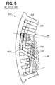
FIG. 9 shows a part of a stator 900 in which large segments 1331 and small segments 1332 are inserted in slots 905 of a stator core 902. An angle θ11 formed between the longitudinal centerline of the slot 905 coincident with a radius of the stator core 902 and the centerline of the large segment 1331 is approximately 110°. An angle θ12 formed between the longitudinal centerline of the slot 905 coincident with a radius of the stator core 902 and the centerline of the large segment 1331 is approximately 90°.
The angle θ11 is larger than the angle θ12. In other words, the turn portion 1331 c is more curved on the inside of the stator core than the outside of the stator core. As a result, the smallest inside diameter R1 of the coil end is smaller than the inside diameter Rso of the stator core 902.
In a stator disclosed in JP-A-9-19108, multi-phase coil windings are inserted in a stator core and only the coil windings in one of the phases are curved toward an outer periphery of the stator core in a turn portion. Since only the coil windings in one of the phases are curved, the lengths of the coil windings and those of the coil windings in other phases are different. In other words, the resistances of the coil windings are different. As a result, the power generation performance decreases.
SUMMARY OF THE INVENTION
The present invention therefore has an objective to provide a rotary electric machine that is advanced in size, power output, and cost, while power generation performance, low fan noise, and ease of production are maintained.
The present invention has another objective to provide a manufacturing method for manufacturing the rotary electric machine.
A rotary electric machine of the present invention includes a rotor, a stator located radially outside the rotor, and a housing enclosing the rotor and the stator. The stator includes a stator core with a plurality of slots in its inner periphery, and a stator coil passing through the slots. The stator coil has insert portions located in the slots and connecting portions connecting the insert portions axially outside of the stator core. Each of the connecting portions has a first curve portion and a second curve portion. The first curve portion is located adjacent to an outer diameter of the stator core and the second curve portion is located adjacent to an inside diameter of the stator core. The first curve portion has curvature larger than that of the second curve portion.
With this configuration, evenness of an inner periphery of a coil end formed by the connecting portions is improved. Also, spaces between the coil end and a cooling air generating member, such as a fan, can be increased. Therefore, noise caused by the cooling air generating member is reduced. Further, since the first and second curve portions are formed on all connecting portions, resistances of conductors forming the stator coil are substantially equal. Therefore, the power generation performance can be maintained.
The stator coil is constructed of U-shaped wires. The U-shaped wire is manufactured by cutting a longitudinal wire into a predetermined length, bending the wire into a substantially U-shape, and forming a first curve portion in a curved portion of the U-shape. The first curve portion is formed on a side which is arranged adjacent to the outer diameter of the stator core. Then, the U-shape wire is twisted in a predetermined shape prior to an installation in the slot.
Since the first curve portion is formed prior to the twist and installation in the slot, the manufacturing process of the rotary electric machine is simplified. Further, manufacturing costs of the same can be reduced.
BRIEF DESCRIPTION OF THE DRAWINGS
The above and other objectives, features and advantages of the present invention will become more apparent from the following detailed description made with reference to the accompanying drawings. In the drawings:
FIG. 1 is a schematic view of a vehicular alternator, partially includes cross-section, according to the embodiment of the present invention;
FIG. 2 is a cross-sectional view of a part of a stator according to the embodiment of the present invention;
FIG. 3 is a perspective view of conductor segments illustrating shapes installed in a stator core according to the embodiment of the present invention;
FIG. 4 is a perspective view of end portions of the conductor segments according to the embodiment of the present invention;
FIG. 5 is a partial end view of the stator core illustrating how the conductor segments are installed in slots according to the embodiment of the present invention;
FIG. 6 is a schematic diagram showing how to produce the conductor segments according to the embodiment of the present invention;
FIG. 7 is a schematic view of the conductor segment produced by the method shown in FIG. 6;
FIG. 8 is a schematic view of a modified conductor segment according to the embodiment of the present invention;
FIG. 9 is a partial end view of a stator core illustrating how conductor segments are installed in the slot, according to a vehicular alternator of a related art;
FIG. 10 is a schematic view of a conductor segment of a related art; and
FIG. 11 is a schematic view of a conductor segment of a related art.
DETAILED DESCRIPTION OF THE PREFERRED EMBODIMENT
The preferred embodiment of the present invention will be explained with reference to the accompanying drawings.
A vehicular alternator 1 shown in FIG. 1 is a three-phase generator and driven by an engine (not shown). The left side and the right side of the alternator 1 in FIG. 1 are referred to as a front end a rear end, respectively. The alternator 1 includes a stator 2, a rotor 3, a housing 4, and a rectifier 5. The rotor 3 rotates with a shaft 6, and functions as a field magnet. The rotor 3 includes a Lundell-type pole core 7, a field coil 8, slip rings 9, 10, a mixed flow fan 11, and a centrifugal fan 12. The shaft 6 is connected to a pulley 20, and rotated by the engine (not shown).
The Lundell-type pole core 7 is constructed of a pair of pole cores. Each pole core includes a boss portion 71 fixed around the shaft 6 and a disc portion 72, which extends from the axial end of the boss portion 71 in the radial direction. Also, the pole core 7 includes sixteen claw poles 73. The field coil 8 is wound around the boss portions 71.
The mixed flow fan 11 includes a base plate 111, inclined blades that are arranged at acute angles to the base plate 111 and right-angled blades that are arranged at right angles to the base plate 111. The base plate 111 is fixed to a front end surface of the pole core 7 by welding or other method, so that the mixed flow fan 11 rotates with the rotor 3. The centrifugal fan 12 includes a base plate 121, and blades that are arranged at right angles to the base plate 121. The base plate 121 is fixed to the rear end surface of the pole core 7 by welding or other method, so that the centrifugal fan 12 rotates with the rotor 3.
The stator 2 functions as an armature. The stator 2 is located to surround the outer periphery of the rotor 3. The stator 2 includes a stator core 32 and a multi-phase stator coil 31. The stator coil 31 is constructed of a plurality of electric conductors. The electric conductors are arranged in slots 35 formed in the inner periphery of the stator core 32. The stator coil 31 protrudes from the rear and front ends of the stator core 32 in the axial direction and forms a first coil end 31 a and a second coil end 31 b.
The housing 4 is constructed of a front housing 4 a and a rear housing 4 b. The housing 4 has air inlet holes 41 on its front and rear end surfaces. The housing 4 also has air outlet holes 42 in the portions opposed to the first coil end 31 a and the second coil end 31 b. The front housing 4 a has a step 4 f on its inner periphery.
The front housing 4 a and the rear housing 4 b are fastened with a stud bolt (fixing member) 4 c such that the stator 2 and rotor 3 are held by the front and rear housings 4 a and 4 b. Specifically, the axial front end of the stator core 32 is in press-contact with the step 4 f by being pressed with a flange 4 f of the stud bolt 4 c in the axial direction, so that the stator core 32 is sandwiched between the step 4 f and the flange 4 g.
The rectifier 5 is fixed to the end of the rear housing 4 b and opposed to the first coil end 31 a. The rectifier 5 rectifies an AC voltage outputted from the stator 2 to a DC voltage.
When rotating power is transferred from the engine to the pulley 20 via a belt and the like, the rotor 3 rotates in the predetermined direction. Under this condition, claw poles 73 of the pole core 7 are energized with application of an exiting voltage to the field coil 8. As a result, a three-phase voltage is generated at the stator coil 31, and a DC current appears at an output terminal 5 a of the rectifier 5.
Next, the stator 2 is described in detail.
As shown in FIG. 2, the stator core 32 has evenly spaced slots 35 opening radially inward of the stator core 32. The electric conductors of the stator coil 31 are arranged in the slots 35 through insulators 34. The insulators 34 provide electric insulation between the stator core 32 and the stator coil 31. The number of slots 35 is determined based on the number of poles of the rotor 3 and the number of the phases of the stator coil 31. In this embodiment, seventy-two slots are formed, for example.
FIG. 3 shows shapes of the electric conductor installed in the slots 35 of the stator core 32. The electric conductors 331, 332 are provided by shaping or twisting substantially U-shaped wires into predetermined shapes. Each conductor has substantially rectangular cross-section in even thickness. The conductors 331, 332 are arranged in a predetermined pattern to construct the stator coil 31.
In each slot 35, even-numbered electric conductors (e.g. four conductors in this embodiment) are installed to pass in the axial direction of the stator core 32. As shown in FIG. 2, straight portions (insert portions) 331 a, 332 a, 332 b, 331 b of the conductors 331, 332 are arranged in line, forming the inner layer (first layer), the inner middle layer (second layer), the outer middle layer (third layer), and the outer layer (fourth layer) in the radially outward direction of the stator core 32.
The first coil end 31 a is constructed of connecting portions (turn portions) 331 c, 332 c of the conductors 331, 332 axially outside the stator core 32. The second coil end 31 b is constructed by connecting ends 331 d, 331 e, 332 d, 332 e of conductors 331, 332 axially outside the stator core 32.
One conductor of one layer in a slot 35 pairs up with one conductor of another layer in a slot 35 that is in one pole pitch next to the slot 35 to maintain spaces between the conductors and to arrange the conductors orderly.
For example, the insert portion 331 a of the first layer pairs up with the insert portion 331 b of the fourth layer in the slot 35 that is one pole pitch next to that the insert portion 331 a passes. The insert portion 332 a of the second layer pairs up with the insert portion 332 b of the third layer in the slot 35 that is one pole pitch next to that the insert portion 332 a passes.
The insert portions 331 a, 332 a are connected to the insert portions 331 b, 332 b through the connecting portions 331 c, 332 c, respectively, at the axially outside the axial rear end of the stator core 32. At the axial end of the stator core 32, the turn portion 331 c located outside the turn portion 332 c. The connecting portions 331 c form outer layer coil ends and the turn portions 332 c form middle layer coil ends. The outer layer coil ends and middle layer coil ends form the first coil end 31 a.
The insert portion 332 a of the second layer also pairs up with the insert portion 331 a′ of the first layer in the slot 35 that is one pole pitch next to that the insert portion 332 a passes. The insert portion 331 b′ of the fourth layer pairs up with the insert portion 332 b of the third layer in the slot 35 that is one pole pitch next to that the insert portion 331 b′ passes. The end 332 d of the insert portion 332 a is connected to the end 331 d′ of the insert portion 331 a′ at the axially outside the axial front end of the stator core 32. The end 331 e′ of the insert portion 331 b′ is connected to the end 332 e of the insert portion 332 b at the axially outside the axial front end of the stator core 32.
The connecting portion of the ends 331 d′ and 332 d and the connecting portion of the ends 332 e and 331 e′ are arranged in the radial direction of the stator core 32, so that adjacent layer coil ends are formed. In this way, the connecting portions of the conductor ends are arranged without overlapping at the axially outside the axial front end of the stator core 32, so that the second coil end 31 b is formed.
Here, the conductor 331 including the insert portions 331 a, 331 b, connecting portion 331 c and ends 331 d, 331 e is referred to as a large segment. The conductor 332 including the insert portions 332 a, 332 b, connecting portion 332 c and ends 332 d, 332 e is referred to as a small segment.
The large segments 331 and the small segments 332 are included in base segments 33. The base segments 33 are arranged in the slots 35 in specific patterns so that the stator coil 31 turning twice around the stator core 32 is formed. However, the segments forming lead-out wires of the stator coil 31 and turn portions connecting the first and second laps of the stator coil 31 are included in special shape segments. The stator coil 31 includes nine special shape segments. The special shaped coil end is formed by connecting the first lap and the second lap, that is, by connecting the inner layer coil end and the outer layer coil end.
Next, the manufacturing process of the stator coil 31 is described.
First, the base segments 33 are arranged such that the turn portions 331 c of the large segments 331 pass outside the turn portions 332 c of the small segments 332. Before installation in the slots 35, the segments 33 are twisted so that the insert portion 331 a and the insert portion 332 a respectively correspond to be in the first layer and second layer in the slot (first slot) 35, and the conductor 332 b and the conductor 331 b respectively correspond to be in the third layer and the fourth layer in another slot (second slot) 35 that is one pole pitch from the first slot in the clockwise direction of the stator core 32. Then, the twisted segments 33 are inserted into the slots 35 from the axial rear end of the stator core 32. Thus, the insert portions 331 a, 331 b, 332 a, and 332 b are arranged in the slots 35 in the manner described above.
After the insertion of the segments 33, the ends of the segments 33, which protrude from the axial front end of the stator core 32, are bent. Specifically, the ends 331 d and 331 e of the large segments 331 are bent as the ends 331 d move from the ends 331 e in the circumferential direction of the stator core 32. Each of the ends 331 d, 331 e of the large segments 331 reaches the point roughly one and a half slots away from the slot 35 that the segment 331 passes. The ends 332 d and 332 e of the small segments 332 are bent as the ends 332 d become close to the end 332 e. Each of the ends 332 d, 332 e reaches the point roughly one and a half slots away.
After the above steps are performed all segments 33 in the slots 35, the end 331 e′ of the fourth layer and the end 332 e of the third layer are electrically connected by welding such as ultrasonic welding, arc welding, and brazing. Likewise, the end 332 d of the second layer and the end 331 d′ of the first layer are electrically connected. When the above steps are completed for all ends as shown in FIG. 4, the second coil end 31 b of the stator 2 is constructed.
When the stator core 2 is viewed from the axial rear end of the stator core 32, the large and small segments 331 and 332 are arranged as show in FIG. 5. An angle θ1 formed between the longitudinal centerline L1 of the slot 35 coincident with a radius of the stator core 32 and the centerline L2 of the segment 331 extending from the first layer is approximately 90°. An angle θ2 formed between the longitudinal centerline L3 of the slot 35 coincident with a radius of the stator core 32 and the centerline L4 of the segment 331 extending from the fourth layer is approximately 100°. That is, the angle θ2 is larger than the angle θ1.
Therefore, in the turn portion 331 c, a curve adjacent to the inner diameter of the stator core 32 is smaller than a curve adjacent to the outer diameter of the stator core 32. The smallest inside diameter D1 of the first coil end 31 a is larger than the inside diameter Dso of the stator core 32. The turn portion 331 c is folded, at a part adjacent to the inner diameter of the stator core 32, toward the outer diameter side of the stator core 32 with respect to an inside diameter contact line of the slot 35. The small segments 332 are arranged in the same manner.
In addition, the smallest inside diameter D1 is larger than the outside diameter Dr of the rotor 3. The largest outside diameter D2 of the base segment 33, that is, the outer diameter of the first coil end 31 a is larger than the outside diameter Ds of the stator core 32. This reduces interference in the coil ends 31 a with the other components. Thus, the height of the coil ends can be reduced. This also reduces the fan noise because a space between the fan and the coil ends 31 a is increased.
The U-shaped wires for providing the segments 331, 332 are manufactured as shown in FIG. 6. First, a longitudinal wire is cut in a certain length to provide a straight wire 100 (step 1). Then, the straight wire 100 is placed in a specified position, and bent substantially into a U-shape by moving a movable pin 210 downward (shown by an arrow A1) (step 2). Thus, a U-shaped wire 200 having a turn portion 202, a first straight portion 205, and a second straight portion 207 is made.
Next, a shaping roller 212 is moved in the horizontal direction (shown by an arrow A2), so that one side of the turn portion 202 is dented to form the curve portion (large curve portion) 204 (step 3), as shown in FIG. 7. The turn portion 202 has a flatter portion 206 on a side opposite to the large curve portion 204. Here, the large curve portion 204 is referred to as a first curve portion and the flatter portion 206 is referred to as a second curve portion. The turn portion 202 corresponds to the turn portion (connecting portion) 331 c, 332 c.
Before installation in the slots 35, the wires 200 are placed as the segments 33 such that the first curve portion 204 is to be adjacent to the outer diameter of the stator core 32 and the second curve portion 206 is to be adjacent to the inner diameter of the stator core 32 (adjacent to the rotor 3). Then, the wires 200 are twisted into the predetermined shape as described above and inserted in the slots 35, so the segments 33 are arranged as shown in FIG. 5.
A part of the first straight portion 205 corresponds to the insert portions 331 b, 332 b which are located in the slot 35 adjacent to the outer diameter of the stator core 32. A part of the second straight portion 207 corresponds to the insert portions 331 a, 332 a which are located in the slot 35 adjacent to the inner diameter of the stator core 32.
Since the turn portions 331 c, 332 c of the segments 331, 332 have the large curve portions 204 on the outer diameter side of the stator core 32 and the flat portions 206 on the inner diameter side, evenness of an inner periphery of the first coil ends 31 a improves. With this, the spaces between the coil ends 31 a, 31 b and the cooling air generating means, such as the mixed flow fan 11 and the centrifugal fan 12 are widened. Therefore, the fan noise is reduced.
Furthermore, curves can be uniformly formed for all segments 33 other than the specific shaped segments. In other words, the segments 33 are produced in the same length (same resistance). As a result, power generation performance can be maintained.
In addition, since the first curve portions 204 are arranged adjacent to the outer diameter side of the stator core 32, the largest outside diameter D2 of the first coil end 31 a is larger than the outside diameter Ds of the stator core 32. With this, the inner diameter H2 of the rear housing 4 b, which faces the first coil end 31 a is larger than the inner diameter H1 of the front housing 4 a. Further, the rear housing 4 b has the air holes 42 at a position facing the first coil end 31 a. Therefore, the cooling performance is improved.
The segment 33 has substantially rectangular shaped cross-sections at least at insert portions, so that the area of the slot 35 occupied by the segments 33 increases. Therefore, high power output can be gained while the size is reduced. The cooling efficiency can be improved at the coil ends 31 a because the air passages in the centrifugal direction increases, as compared with segments having circular-shaped cross-sections in the same cross-sectional areas.
The production of the stator 2 can be easier and reduced in cost by using the U-shaped wire 200 to form the stator coil 31. However, the present invention should not be limited to the embodiment previously discussed and shown in the figures, but may be implemented in various ways without departing from the spirit of the invention.
For instance, the second curve portion 206 may be slightly curved, as shown in FIG. 8. A U-shaped wire 200A has the small curve portion 208 on a side arranged to be adjacent to the inner diameter of the stator core 32, and the large curve portion 204 on a side arranged adjacent to the outer diameter side of the stator core 32. Curvature of the first curve portion 204 is larger than that of the second curve portion 208. To produce the U-shaped wire 200A, two shaping rollers 212 are used in the step 3. The first curve portion 204 and the second curve portion 208 are formed by applying forces with the two rollers 212 from both sides of the wire 200A.
The present invention can be applied to any kind of rotor electric devices other than the one for vehicular power generators.