EP1736715A1 - Tubes à vide pour collecteurs solaires avec transfert de chaleur amélioré - Google Patents
Tubes à vide pour collecteurs solaires avec transfert de chaleur amélioré Download PDFInfo
- Publication number
- EP1736715A1 EP1736715A1 EP05013591A EP05013591A EP1736715A1 EP 1736715 A1 EP1736715 A1 EP 1736715A1 EP 05013591 A EP05013591 A EP 05013591A EP 05013591 A EP05013591 A EP 05013591A EP 1736715 A1 EP1736715 A1 EP 1736715A1
- Authority
- EP
- European Patent Office
- Prior art keywords
- heat transfer
- tube
- heat
- vacuum tube
- heat exchanger
- Prior art date
- Legal status (The legal status is an assumption and is not a legal conclusion. Google has not performed a legal analysis and makes no representation as to the accuracy of the status listed.)
- Withdrawn
Links
- 229910002804 graphite Inorganic materials 0.000 claims abstract description 47
- 239000010439 graphite Substances 0.000 claims abstract description 47
- OKTJSMMVPCPJKN-UHFFFAOYSA-N Carbon Chemical compound [C] OKTJSMMVPCPJKN-UHFFFAOYSA-N 0.000 claims abstract description 46
- 239000006096 absorbing agent Substances 0.000 claims abstract description 24
- 239000011521 glass Substances 0.000 claims description 34
- 239000011888 foil Substances 0.000 claims description 12
- 230000002093 peripheral effect Effects 0.000 claims description 4
- 239000002131 composite material Substances 0.000 claims description 2
- 239000000306 component Substances 0.000 description 14
- 239000013529 heat transfer fluid Substances 0.000 description 9
- 238000000465 moulding Methods 0.000 description 9
- 239000000463 material Substances 0.000 description 6
- 238000000034 method Methods 0.000 description 6
- RYGMFSIKBFXOCR-UHFFFAOYSA-N Copper Chemical compound [Cu] RYGMFSIKBFXOCR-UHFFFAOYSA-N 0.000 description 5
- 229910052802 copper Inorganic materials 0.000 description 5
- 239000010949 copper Substances 0.000 description 5
- 238000004519 manufacturing process Methods 0.000 description 5
- 229910052782 aluminium Inorganic materials 0.000 description 4
- XAGFODPZIPBFFR-UHFFFAOYSA-N aluminium Chemical compound [Al] XAGFODPZIPBFFR-UHFFFAOYSA-N 0.000 description 4
- 239000007788 liquid Substances 0.000 description 4
- 238000010521 absorption reaction Methods 0.000 description 2
- 238000001704 evaporation Methods 0.000 description 2
- 238000007373 indentation Methods 0.000 description 2
- 229910052751 metal Inorganic materials 0.000 description 2
- 239000002184 metal Substances 0.000 description 2
- 230000005855 radiation Effects 0.000 description 2
- 229910001369 Brass Inorganic materials 0.000 description 1
- 229910002651 NO3 Inorganic materials 0.000 description 1
- NHNBFGGVMKEFGY-UHFFFAOYSA-N Nitrate Chemical compound [O-][N+]([O-])=O NHNBFGGVMKEFGY-UHFFFAOYSA-N 0.000 description 1
- 230000006978 adaptation Effects 0.000 description 1
- 239000000654 additive Substances 0.000 description 1
- 230000000996 additive effect Effects 0.000 description 1
- 239000011230 binding agent Substances 0.000 description 1
- 239000010951 brass Substances 0.000 description 1
- 230000015556 catabolic process Effects 0.000 description 1
- 150000001875 compounds Chemical class 0.000 description 1
- 230000005494 condensation Effects 0.000 description 1
- 238000009833 condensation Methods 0.000 description 1
- 238000010276 construction Methods 0.000 description 1
- 230000008602 contraction Effects 0.000 description 1
- PMHQVHHXPFUNSP-UHFFFAOYSA-M copper(1+);methylsulfanylmethane;bromide Chemical compound Br[Cu].CSC PMHQVHHXPFUNSP-UHFFFAOYSA-M 0.000 description 1
- 230000007423 decrease Effects 0.000 description 1
- 238000006731 degradation reaction Methods 0.000 description 1
- 230000000694 effects Effects 0.000 description 1
- 230000008020 evaporation Effects 0.000 description 1
- 239000004744 fabric Substances 0.000 description 1
- 239000007789 gas Substances 0.000 description 1
- -1 graphite salts Chemical class 0.000 description 1
- QAOWNCQODCNURD-UHFFFAOYSA-M hydrogensulfate Chemical compound OS([O-])(=O)=O QAOWNCQODCNURD-UHFFFAOYSA-M 0.000 description 1
- 230000002687 intercalation Effects 0.000 description 1
- 238000009830 intercalation Methods 0.000 description 1
- 239000012533 medium component Substances 0.000 description 1
- 239000002245 particle Substances 0.000 description 1
- 238000007789 sealing Methods 0.000 description 1
- 239000007787 solid Substances 0.000 description 1
- 239000013585 weight reducing agent Substances 0.000 description 1
- 238000009736 wetting Methods 0.000 description 1
Images


Classifications
-
- F—MECHANICAL ENGINEERING; LIGHTING; HEATING; WEAPONS; BLASTING
- F28—HEAT EXCHANGE IN GENERAL
- F28F—DETAILS OF HEAT-EXCHANGE AND HEAT-TRANSFER APPARATUS, OF GENERAL APPLICATION
- F28F21/00—Constructions of heat-exchange apparatus characterised by the selection of particular materials
- F28F21/02—Constructions of heat-exchange apparatus characterised by the selection of particular materials of carbon, e.g. graphite
-
- F—MECHANICAL ENGINEERING; LIGHTING; HEATING; WEAPONS; BLASTING
- F24—HEATING; RANGES; VENTILATING
- F24S—SOLAR HEAT COLLECTORS; SOLAR HEAT SYSTEMS
- F24S10/00—Solar heat collectors using working fluids
- F24S10/40—Solar heat collectors using working fluids in absorbing elements surrounded by transparent enclosures, e.g. evacuated solar collectors
- F24S10/45—Solar heat collectors using working fluids in absorbing elements surrounded by transparent enclosures, e.g. evacuated solar collectors the enclosure being cylindrical
-
- F—MECHANICAL ENGINEERING; LIGHTING; HEATING; WEAPONS; BLASTING
- F28—HEAT EXCHANGE IN GENERAL
- F28F—DETAILS OF HEAT-EXCHANGE AND HEAT-TRANSFER APPARATUS, OF GENERAL APPLICATION
- F28F13/00—Arrangements for modifying heat-transfer, e.g. increasing, decreasing
-
- F—MECHANICAL ENGINEERING; LIGHTING; HEATING; WEAPONS; BLASTING
- F24—HEATING; RANGES; VENTILATING
- F24S—SOLAR HEAT COLLECTORS; SOLAR HEAT SYSTEMS
- F24S80/00—Details, accessories or component parts of solar heat collectors not provided for in groups F24S10/00-F24S70/00
- F24S2080/01—Selection of particular materials
- F24S2080/014—Carbone, e.g. graphite
-
- Y—GENERAL TAGGING OF NEW TECHNOLOGICAL DEVELOPMENTS; GENERAL TAGGING OF CROSS-SECTIONAL TECHNOLOGIES SPANNING OVER SEVERAL SECTIONS OF THE IPC; TECHNICAL SUBJECTS COVERED BY FORMER USPC CROSS-REFERENCE ART COLLECTIONS [XRACs] AND DIGESTS
- Y02—TECHNOLOGIES OR APPLICATIONS FOR MITIGATION OR ADAPTATION AGAINST CLIMATE CHANGE
- Y02E—REDUCTION OF GREENHOUSE GAS [GHG] EMISSIONS, RELATED TO ENERGY GENERATION, TRANSMISSION OR DISTRIBUTION
- Y02E10/00—Energy generation through renewable energy sources
- Y02E10/40—Solar thermal energy, e.g. solar towers
- Y02E10/44—Heat exchange systems
Definitions
- the present invention relates to vacuum tubes for solar collectors.
- FIG. 1 A known type of vacuum tube solar collectors ( Figure 1) contains so-called Sydney tubes. These are like a Thennoskanne constructed double-walled glass vessels consisting of two concentric nested glass tubes 1 and 2, which are each hemispherical sealed at one end and fused together at the other end (not visible in the cross-sectional view of Figure 1).
- the hermetically sealed gap 3 between the glass tubes is evacuated to prevent heat loss.
- a support structure 4 heat transfer tube for example, a U-shaped tube, which is flowed through by a heat transfer fluid.
- FIG. 1 shows the two legs 5 ', 5''of the U-tube for the inflow of the heated and the outflow of the heated heat transfer fluid to the heat exchanger or storage.
- Most of the support structure contains 4 heat conducting plates 6 made of aluminum or copper, in which the usually made of copper or brass heat transfer tubes are embedded or folded.
- the U-shaped pipe guide are also other types of execution and Operation of the heat transfer tube known.
- the wetting carrier liquid may flow longitudinally through the collector tube, then the tube carrier tube is open at the top and at the bottom of the collector tube.
- the flow is located in a collection box at the lower end of the pipe, and at the upper end of the pipe there is a collection box for the return
- the heat carrier tube can also be flowed through coaxially.
- the heat transfer tube consists of two coaxially arranged tubes, wherein the open end of the inner coaxial tube (heat supply tube) is surmounted by the closed end of the outer coaxial tube.
- Such a guide of the heat transfer fluid is for example in the patent DE 198 21 137 described.
- the condensed liquid then flows back to the lower end of the heat pipe back, so that the described evaporation and condensation process can proceed, the tubes must be constructed with a minimum slope from the horizontal
- the inner glass tube (absorber tube) 2 is provided on its vacuum gap facing surface with a selective absorber layer 7, for example made of aluminum nitride.
- a highly reflective mirror 8 arranged behind the collector tubes causes the solar radiation to reach the rear side of the cylindrical absorber tube. From the incident solar radiation 7 heat is absorbed in the absorber layer. About theticianleitbleche 6, the heat is transferred to the heat transfer tubes.
- the heated heat transfer fluid flows to a heat exchanger in which the heat is decoupled for further use.
- the heat transfer resistance between the absorber tube 2 and the heat transfer tubes is relatively high, because in the known support structures 4 with politicians 6 is only a relatively limited contact surface for heat transfer available. Due to the rigidity of these materials and always existing unevenness and irregularities on the surfaces, it is not possible to realize a seamless fit between metallic components or metal and glass, so that always insulating air bridges are present. In addition, in the course of the life of the collector due to increasing material fatigue due to the frequent passage of temperature-induced expansion and contraction cycles to expect an increasing degradation of the positive connection. Another problem is the different thermal expansion of copper and aluminum, when heat conducting aluminum sheets and heat transfer tubes made of copper are used.
- heat-conducting elements made of pressed graphite expandate.
- Graphite expandate is characterized by a high thermal conductivity as well as an easy formability and excellent adaptation to adjacent surfaces. Therefore, by means of compressed graphite expander, it is possible to achieve a virtually complete full-surface positive connection between the heat-transferring components.
- a heat conducting element made of pressed graphite expander is arranged in the inner glass tube 2 with full-surface positive locking on the one hand to the Contact surfaces of thedaleleitelements with the inner wall of the inner glass tube 2 and on the other hand to the heat transfer tubes and possibly a heat carrier tubes receiving support structure.
- the invention is not bound to a specific type of pipe guide of the heat transfer medium, it is suitable both for U-shaped and flowed through from bottom to top and koxiale heat transfer tubes or heat pipes or combinations thereof. Therefore, the general term heat transfer tubes is used in the following, unless reference is made to a specific tube assembly. Due to the full-surface positive engagement between the inner wall of the inner glass tube 2 and the heat conducting element of expanded graphite, there are no friction points between glass and metal in the inventive arrangement, in contrast to the prior art. This will prevent damage to the glass tube. The thermal expansion of the expanded graphite is minimal, therefore no significant material fatigue of the heat conducting element is to be expected in the course of the service life of the solar collector.
- the heat-conducting element made of pressed graphite expanded material can be designed, for example, as a form-fitting intermediate layer between the absorber inner wall and the support structure accommodating the heat transfer tubes or as being fitted into the absorber tube Heat exchanger component, ie as a molded part, which receives the heat transfer tubes form-fitting and replaces the support structure with the rondleitblechen.
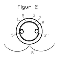
- the two basic variants of the invention are exemplified by, but not limited to, a Sydney collector with U-shaped heat transfer tube 5 ', 5 "
- the heat transfer fluid may also be through a coaxial tube or from below flowed upward pipe or a heat pipe is used.
- the support structure is wrapped with the heat transfer tubes on its inner wall of the absorber tube 2 facing surface with graphite foil, which produces a positive heat-conducting contact between the absorber tube 2 and the heat transfer tubes.
- the support structure itself is not shown in Figure 2 for the sake of clarity.
- graphite foil adapts easily to the surfaces to be sealed and thereby compensates for bumps or other irregularities in the surface of flanges
- the graphite foil 9 fits exactly the subsequent surfaces of the support structure and the heat transfer tubes on the one hand and the inner wall the inner glass tube 2 on the other hand, thus compensating existing irregularities of these surfaces. This facilitates the heat transfer.
- a graphite foil is to be selected which on the one hand is sufficiently tear-resistant, on the other hand sufficiently flexible so that it can be wound.
- Suitable graphite foil has a thickness between 0.1 and 1 mm, preferably up to 0.5 mm, and a density between 0.5 and 1.5 g / cm 3 .
- the support structure made of heat-conducting sheets, which accommodates the heat-transfer tubes, is substituted by a molded part made of pressed graphite expandate.
- This is referred to below as the heat transfer member 10.
- the heat exchanger components 10 according to the invention have a substantially cylindrical shape with recesses for receiving the heat transfer tubes.
- the planteübeannosbauteil 10 is dimensioned so that its peripheral surface at least partially positively connected to the inner wall of the inner glass tube 2 (absorber tube) connects.
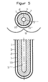
- the heat transfer tubes shown by way of example in FIG. 3 as a U-tube 5 ', 5 ", are in turn received in a form-fitting manner by the heat transfer member 10 of compressed graphite expandate.
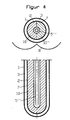
- the heat exchanger component 10 may be formed as a one-piece molded part, but for manufacturing reasons, it is, as shown in Figures 3-5, preferably composed of two half-molded parts 10 'and 10 ".
- Figure 4 shows in transverse and longitudinal section a double-walled glass tube 1, 2, in which the heat transfer fluid is passed through a coaxial tube 5 '''.
- the Kaxialrohr is between the two half-mold parts 10 ', 10 ", whose abutting surfaces have corresponding recesses, embedded form fit.
- Figure 5 shows a further alternative in transverse and longitudinal section a double-walled glass tube 1, 2, in which the heat transfer fluid through a heat pipe 5 '''' is performed.
- the heat-pipe is between the two half-mold parts 10 ', 10'', whose abutting surfaces have corresponding recesses, embedded form fit.
- graphite expandate and graphite foil The production of graphite expandate and graphite foil is known.
- Graphite intercalation compounds graphite salts
- graphite hydrogen sulfate or graphite nitrate are shock-heated in an oven or by means of microwaves.
- the volume of the particles increases by a factor of 200 to 400, and the bulk density drops to 2 to 20 g / l.
- the resulting graphite expandate consists of worm or ziehharnionika-shaped aggregates.
- the density of the graphite expandate in these moldings ranges between 0.02 and 0.5 g / cm 3 .
- the moldings can also be made by form extracting from prefabricated panels. If the heat exchanger component to be used in an already provided with heat transfer tubes vacuum tube, so must be provided in the molding recesses for receiving the heat transfer tubes or the heat pipe. Thanks to the easy workability of pressed pieces of expanded graphite, the recesses can be pressed into the molded part without difficulty or cut out of it. The molded part is then pushed from the open end into the vacuum tube, wherein the heat transfer tubes slide into the recesses provided for this purpose.
- a complete component comprising the heat carrier tube and the heat transfer medium component pressed from expanded graphite.
- the heat transfer tube is simply pressed into the molding, which may consist of two juxtaposed half moldings, or embedded between the two half moldings, so that it is received positively.
- the invention is optimally realized because of the full-surface fit over the entire available inner wall surface of the absorber tube 2. In principle, deviations from the cylindrical shape are conceivable, for example by recesses or indentations at the round cross-section of the cylinder.
- substantially cylindrical shaped parts are to be understood as having a geometry that can be regarded as derived from a cylinder such that its originally round cross section is provided with indentations or recesses , so that the peripheral surface of this structure corresponds only in limited areas of the peripheral surface of a cylinder.
- the surface of the heat exchanger component 10 facing the inner wall of the inner glass tube 2 is provided with an absorber layer. This variant has the advantage that the heat transfer through the glass wall of the tube 2 is eliminated.
- the absorption layer 7 can also be completely dispensed with and the absorption effect of the graphite can be utilized.
- Related loss of efficiency is compensated by savings in material and manufacturing costs, which also favors use in poorer countries, many of which are located in high-energy shores.
Landscapes
- Engineering & Computer Science (AREA)
- Physics & Mathematics (AREA)
- Thermal Sciences (AREA)
- Mechanical Engineering (AREA)
- General Engineering & Computer Science (AREA)
- Sustainable Development (AREA)
- Life Sciences & Earth Sciences (AREA)
- Sustainable Energy (AREA)
- Chemical & Material Sciences (AREA)
- Combustion & Propulsion (AREA)
- Rigid Pipes And Flexible Pipes (AREA)
- Joining Of Glass To Other Materials (AREA)
- Heat-Exchange Devices With Radiators And Conduit Assemblies (AREA)
Priority Applications (6)
| Application Number | Priority Date | Filing Date | Title |
|---|---|---|---|
| EP05013591A EP1736715A1 (fr) | 2005-06-23 | 2005-06-23 | Tubes à vide pour collecteurs solaires avec transfert de chaleur amélioré |
| KR1020087001756A KR20080031308A (ko) | 2005-06-23 | 2006-05-16 | 개선된 열 전달을 갖는 태양열 수집기 용 진공 튜브들 |
| PCT/EP2006/004602 WO2006136243A1 (fr) | 2005-06-23 | 2006-05-16 | Tubes a vide de collecteurs solaires au transfert de chaleur ameliore |
| JP2008517345A JP2008544206A (ja) | 2005-06-23 | 2006-05-16 | 改善された熱移行を伴う太陽集熱器に用いられる真空管 |
| CNA200680021135XA CN101198827A (zh) | 2005-06-23 | 2006-05-16 | 用于太阳能收集器的具有改善的传热的真空管 |
| US11/964,291 US20080156314A1 (en) | 2005-06-23 | 2007-12-26 | Vacuum tubes for solar collectors with improved heat transfer |
Applications Claiming Priority (1)
| Application Number | Priority Date | Filing Date | Title |
|---|---|---|---|
| EP05013591A EP1736715A1 (fr) | 2005-06-23 | 2005-06-23 | Tubes à vide pour collecteurs solaires avec transfert de chaleur amélioré |
Publications (1)
| Publication Number | Publication Date |
|---|---|
| EP1736715A1 true EP1736715A1 (fr) | 2006-12-27 |
Family
ID=35456069
Family Applications (1)
| Application Number | Title | Priority Date | Filing Date |
|---|---|---|---|
| EP05013591A Withdrawn EP1736715A1 (fr) | 2005-06-23 | 2005-06-23 | Tubes à vide pour collecteurs solaires avec transfert de chaleur amélioré |
Country Status (6)
| Country | Link |
|---|---|
| US (1) | US20080156314A1 (fr) |
| EP (1) | EP1736715A1 (fr) |
| JP (1) | JP2008544206A (fr) |
| KR (1) | KR20080031308A (fr) |
| CN (1) | CN101198827A (fr) |
| WO (1) | WO2006136243A1 (fr) |
Cited By (7)
| Publication number | Priority date | Publication date | Assignee | Title |
|---|---|---|---|---|
| FR2919712A1 (fr) * | 2007-08-02 | 2009-02-06 | Claude Alix Georges Pomero | Capteur solaire thermique avec absorbeur en forme de cylindre transparent a section ellipsoidale contenant de l'eau coloree |
| DE102008051905A1 (de) * | 2008-10-16 | 2010-07-15 | Sgl Carbon Se | Verfahren zur Herstellung von Wärmetauscherrohren |
| CN101813394A (zh) * | 2010-04-04 | 2010-08-25 | 姚德龙 | 一种太阳能热水器集热器高导热翅片 |
| CN101581508B (zh) * | 2009-06-29 | 2011-01-26 | 浙江高得乐新能源有限公司 | 带有热加速器的太阳能真空集热管 |
| CN103363689A (zh) * | 2013-08-09 | 2013-10-23 | 吴健 | 利用固体介质换热的热管式太阳能集热器 |
| EP2733438A1 (fr) * | 2012-11-19 | 2014-05-21 | Viessmann Werke GmbH & Co. KG | Collecteur solaire |
| EP2827078A1 (fr) * | 2013-07-17 | 2015-01-21 | Urs Furter | Collecteur solaire pour chauffer un fluide en circulation et procédé pour fabriquer un collecteur solaire |
Families Citing this family (21)
| Publication number | Priority date | Publication date | Assignee | Title |
|---|---|---|---|---|
| SK842007A3 (sk) * | 2007-06-19 | 2009-01-07 | Schener S. R. O. | Absorbér solárnej vákuovej trubice |
| US7971587B2 (en) | 2007-10-31 | 2011-07-05 | The Regents Of The University Of California | Apparatus and method for solar thermal energy collection |
| CN101387449B (zh) * | 2008-10-08 | 2010-06-02 | 大连理工大学 | 石墨填充真空玻璃管开式毛细管太阳能集热管 |
| CN101387447B (zh) * | 2008-10-08 | 2010-06-09 | 大连理工大学 | 石墨填充真空玻璃管闭环毛细管太阳能集热管 |
| KR101030691B1 (ko) * | 2008-12-05 | 2011-04-27 | (주)해빛에너지 | 진공관을 이용한 태양열 집열기의 전열판 |
| FR2942030B1 (fr) * | 2009-02-12 | 2012-10-19 | Sophia Antipolis En Dev | Ensemble de caloducs pour capteurs solaires |
| CA2673703C (fr) * | 2009-07-23 | 2015-05-05 | Huazi Lin | Appareils de cuisson solaire |
| CA2672760C (fr) * | 2009-07-23 | 2017-10-17 | Huazi Lin | Cafetiere/theiere et appareils de cuisson solaire |
| SE534515C2 (sv) * | 2009-12-09 | 2011-09-20 | Climatewell Ab Publ | Termisk solfångare med inbyggd kemisk värmepump |
| JP2012002484A (ja) * | 2010-06-21 | 2012-01-05 | Daiwa House Industry Co Ltd | 太陽熱集熱パネル構造 |
| KR101155691B1 (ko) * | 2010-07-19 | 2012-06-12 | 주식회사 써너지 | 태양열 집열판용 진공집열관 |
| KR101002413B1 (ko) | 2010-07-21 | 2010-12-17 | 삼신설계(주) | 태양열 에너지와 물의 이송 기술을 이용한 태양열 집열 시스템 |
| US20120073567A1 (en) * | 2010-09-23 | 2012-03-29 | Roland Winston | Solar thermal concentrator apparatus, system, and method |
| FR3034506B1 (fr) | 2015-03-31 | 2017-05-05 | Commissariat Energie Atomique | Conducteur thermique multi-elements pour tube sous vide d'un capteur solaire thermique a double tubes sous vide |
| WO2017002127A1 (fr) * | 2015-06-27 | 2017-01-05 | Indian Institute Of Technology Bombay | Collecteur solaire à stockage de chaleur intégré dans un absorbeur |
| WO2017210674A1 (fr) * | 2016-06-03 | 2017-12-07 | The Trustees Of Columbia University In The City Of New York | Chauffe-eau solaire sans réservoir utilisant des tubes à vide sans fond |
| KR101924418B1 (ko) | 2016-09-27 | 2019-02-20 | 강민수 | 태양광 집광집열관 |
| IT201700109097A1 (it) * | 2017-09-28 | 2019-03-28 | Archimede Sistemi Ind S R L S | Dispositivo convertitore di energia solare, reattore solare corrispondente, e relativo impianto |
| US11519655B2 (en) | 2020-07-31 | 2022-12-06 | Photon Vault, Llc | Thermal energy storage and retrieval systems and methods |
| US11428476B2 (en) | 2020-09-04 | 2022-08-30 | Photon Vault, Llc | Thermal energy storage and retrieval system |
| US20220146151A1 (en) * | 2020-11-09 | 2022-05-12 | Photon Vault, Llc | Multi-temperature heat collection system |
Citations (16)
| Publication number | Priority date | Publication date | Assignee | Title |
|---|---|---|---|---|
| US4031862A (en) * | 1976-03-10 | 1977-06-28 | Smith Frank J | Economizer |
| FR2365761A1 (fr) * | 1976-09-27 | 1978-04-21 | Gen Electric | Collecteur solaire |
| FR2444238A1 (fr) * | 1978-12-12 | 1980-07-11 | Lampes Sa | Element de transfert thermique place entre l'enveloppe d'un capteur et un circuit de circulation d'un fluide caloporteur, et capteur solaire ainsi equipe |
| US4432408A (en) * | 1982-07-19 | 1984-02-21 | The Dow Chemical Co. | Method and compressed vermicular expanded graphite apparatus for heat exchanging |
| US4440156A (en) * | 1981-07-06 | 1984-04-03 | Nitto Kohki Co., Ltd. | Solar heat collector |
| JPS6122572A (ja) * | 1984-07-09 | 1986-01-31 | Hitachi Ltd | 燃料電池の製造方法 |
| FR2600073A1 (fr) * | 1986-06-16 | 1987-12-18 | Lorraine Carbone | Contact thermique a fort coefficient de transfert et applications |
| FR2610088A1 (fr) * | 1987-01-23 | 1988-07-29 | Lorraine Carbone | Dispositif de refroidissement d'une structure soumise a un flux thermique intense et procede de realisation de ce dispositif |
| EP0458150A1 (fr) * | 1990-05-24 | 1991-11-27 | Bayer Ag | Procédé pour fabriquer des pièces moulées |
| EP0515891A1 (fr) * | 1991-05-25 | 1992-12-02 | Bayer Ag | Procédé pour la préparation de corps moulés en graphite expansé |
| DE29819832U1 (de) * | 1998-02-28 | 1999-01-28 | Thermomax Ltd | Vakkuum-Solarkollektor mit Reflektor |
| DE10022972A1 (de) * | 2000-05-11 | 2001-11-22 | Bosch Gmbh Robert | Mikrostruktur-Wärmetauscher und Verfahren zu dessen Herstellung |
| WO2003057475A1 (fr) * | 2001-12-26 | 2003-07-17 | Graftech Inc. | Materiau d'interface thermique ameliore |
| WO2004094924A2 (fr) * | 2003-04-22 | 2004-11-04 | Solargenix Energy Llc | Capteurs solaires avec recepteur sous vide et reflecteurs externes non imageurs |
| EP1512933A2 (fr) * | 2003-09-04 | 2005-03-09 | Sgl Carbon Ag | Plate conductrice de chaleur en graphite expansé et sa méthode de fabrication |
| FR2860512A1 (fr) * | 2003-10-06 | 2005-04-08 | Silva Serge Da | Procede de fabrication d'objets composites utilisant du graphite et de la vermiculite expanses |
Family Cites Families (58)
| Publication number | Priority date | Publication date | Assignee | Title |
|---|---|---|---|---|
| US915059A (en) * | 1908-06-17 | 1909-03-09 | Dennis O Brien | Protective covering for blow-off pipes of steam-boilers and the like. |
| US980505A (en) * | 1909-06-01 | 1911-01-03 | Gen Electric | Apparatus for utilizing solar heat. |
| US1345758A (en) * | 1919-02-14 | 1920-07-06 | Arthur V Folsom | Solar steam-generator |
| US1871508A (en) * | 1930-07-02 | 1932-08-16 | Henry A Gardner | Metallic conduit |
| US1989999A (en) * | 1933-06-07 | 1935-02-05 | Niederle Max | Solar water heater |
| US2205378A (en) * | 1938-03-12 | 1940-06-25 | Abbot Charles Greeley | Solar flash boiler |
| US2247830A (en) * | 1938-07-07 | 1941-07-01 | Charles G Abbot | Solar heater |
| US2460482A (en) * | 1945-02-20 | 1949-02-01 | Abbot Charles Greeley | Solar heat collector |
| US2856905A (en) * | 1955-04-04 | 1958-10-21 | Oxy Catalyst Inc | Heat generating and exchanging device |
| GB991581A (en) * | 1962-03-21 | 1965-05-12 | High Temperature Materials Inc | Expanded pyrolytic graphite and process for producing the same |
| US3323869A (en) * | 1963-12-19 | 1967-06-06 | Dow Chemical Co | Process for producing expanded graphite |
| US3322979A (en) * | 1964-03-31 | 1967-05-30 | Texas Instruments Inc | Thermionic energy converter |
| US3265124A (en) * | 1964-07-10 | 1966-08-09 | Falls Ind Inc | Coated graphite products |
| US3379394A (en) * | 1964-10-27 | 1968-04-23 | Navy Usa | Optical solar energy converter |
| US3327777A (en) * | 1964-11-09 | 1967-06-27 | Union Carbide Corp | Heat interchanger |
| US3389964A (en) * | 1966-04-04 | 1968-06-25 | Dow Chemical Co | Process for preparing low density graphite structrues |
| US3815574A (en) * | 1973-06-01 | 1974-06-11 | G Gaydos | Solar heating system |
| US4099514A (en) * | 1974-01-07 | 1978-07-11 | Mario Posnansky | Method and apparatus for heating a fluid medium by means of solar energy |
| US3952724A (en) * | 1974-06-24 | 1976-04-27 | Owens-Illinois, Inc. | Solar energy converter |
| US3914100A (en) * | 1974-07-29 | 1975-10-21 | Wheeling Pittsburgh Steel Corp | Pipe protective covering |
| US3964929A (en) * | 1975-07-21 | 1976-06-22 | United Technologies Corporation | Fuel cell cooling system with shunt current protection |
| US4067315A (en) * | 1975-10-24 | 1978-01-10 | Corning Glass Works | Solar heat pipe |
| US4120285A (en) * | 1976-11-01 | 1978-10-17 | Owens-Illinois, Inc. | Modular tubular solar energy collector apparatus |
| US4186724A (en) * | 1976-11-22 | 1980-02-05 | American Solar | Solar energy collector |
| US4153039A (en) * | 1977-01-07 | 1979-05-08 | Carroll John H | Focusing solar energy apparatus |
| US4233957A (en) * | 1978-02-16 | 1980-11-18 | Corning Glass Works | Solar energy collector |
| US4265952A (en) * | 1978-03-23 | 1981-05-05 | The Dow Chemical Company | Vermicular expanded graphite composite material |
| US4199628A (en) * | 1978-03-23 | 1980-04-22 | The Dow Chemical Company | Vermicular expanded graphite composite material |
| US4304267A (en) * | 1978-10-12 | 1981-12-08 | Campbell Frank Jun | Interlocking refractory for covering a pipe |
| US4355684A (en) * | 1979-06-13 | 1982-10-26 | The Dow Chemical Company | Uniaxially compressed vermicular expanded graphite for heat exchanging |
| US4349013A (en) * | 1979-06-25 | 1982-09-14 | Alpha Solarco Inc. | Solar energy receivers |
| US4250958A (en) * | 1979-07-16 | 1981-02-17 | Wasserman Kurt J | Double tubular thermal energy storage element |
| CA1161324A (fr) * | 1979-08-29 | 1984-01-31 | Jacques M. Hanlet | Collecteur d'energie electromagnetique |
| US4259946A (en) * | 1979-10-22 | 1981-04-07 | Thermacore, Inc. | Solar collector |
| US4233369A (en) * | 1979-10-29 | 1980-11-11 | United Technologies Corporation | Fuel cell cooler assembly and edge seal means therefor |
| US4340035A (en) * | 1980-04-24 | 1982-07-20 | Begun James A | Solar collector |
| US4324844A (en) * | 1980-04-28 | 1982-04-13 | Westinghouse Electric Corp. | Variable area fuel cell cooling |
| JPS5838708B2 (ja) * | 1981-03-06 | 1983-08-24 | 工業技術院長 | 太陽熱集熱器 |
| JPS5844284Y2 (ja) * | 1981-07-06 | 1983-10-07 | 日東工器株式会社 | 真空二重管型太陽熱集熱管 |
| US4471837A (en) * | 1981-12-28 | 1984-09-18 | Aavid Engineering, Inc. | Graphite heat-sink mountings |
| US4945010A (en) * | 1983-06-02 | 1990-07-31 | Engelhard Corporation | Cooling assembly for fuel cells |
| US4520795A (en) * | 1983-12-09 | 1985-06-04 | Parkyn William A | Solar collector having tank and glazing construction |
| JPH0328267Y2 (fr) * | 1986-05-30 | 1991-06-18 | ||
| JPS6343045U (fr) * | 1986-09-06 | 1988-03-22 | ||
| US4776790A (en) * | 1986-12-22 | 1988-10-11 | Norton Company | Refractory shields for curved and straight superheater tubes |
| US4993403A (en) * | 1988-03-11 | 1991-02-19 | Downs Charles W | Method and apparatus for trapping heat energy |
| JP2620606B2 (ja) * | 1990-05-16 | 1997-06-18 | 東洋炭素株式会社 | 高純度可撓性膨張黒鉛シート及びその製造方法 |
| US5074283A (en) * | 1990-08-10 | 1991-12-24 | The United States Department Of Energy | Thermal storage module for solar dynamic receivers |
| JPH0519861U (ja) * | 1991-08-21 | 1993-03-12 | シロキ工業株式会社 | 太陽熱温水装置における真空二重集熱管 |
| JP3087929B2 (ja) * | 1992-10-26 | 2000-09-18 | 日本電気硝子株式会社 | 真空式太陽熱集熱器 |
| US5523260A (en) * | 1993-08-02 | 1996-06-04 | Motorola, Inc. | Method for heatsinking a controlled collapse chip connection device |
| JPH07324826A (ja) * | 1994-05-30 | 1995-12-12 | Shiroki Corp | 真空二重ガラス管 |
| US5724923A (en) * | 1995-05-19 | 1998-03-10 | Saint-Gobain/Norton Industrial Ceramics Corp. | Refractory shield design for superheater tubes |
| US6503626B1 (en) * | 2000-02-25 | 2003-01-07 | Graftech Inc. | Graphite-based heat sink |
| US6538892B2 (en) * | 2001-05-02 | 2003-03-25 | Graftech Inc. | Radial finned heat sink |
| US6619283B2 (en) * | 2001-09-11 | 2003-09-16 | Manu Ghela | Solar collector pipe |
| US6771502B2 (en) * | 2002-06-28 | 2004-08-03 | Advanced Energy Technology Inc. | Heat sink made from longer and shorter graphite sheets |
| US20070158050A1 (en) * | 2006-01-06 | 2007-07-12 | Julian Norley | Microchannel heat sink manufactured from graphite materials |
-
2005
- 2005-06-23 EP EP05013591A patent/EP1736715A1/fr not_active Withdrawn
-
2006
- 2006-05-16 JP JP2008517345A patent/JP2008544206A/ja active Pending
- 2006-05-16 WO PCT/EP2006/004602 patent/WO2006136243A1/fr active Application Filing
- 2006-05-16 CN CNA200680021135XA patent/CN101198827A/zh active Pending
- 2006-05-16 KR KR1020087001756A patent/KR20080031308A/ko not_active Application Discontinuation
-
2007
- 2007-12-26 US US11/964,291 patent/US20080156314A1/en not_active Abandoned
Patent Citations (16)
| Publication number | Priority date | Publication date | Assignee | Title |
|---|---|---|---|---|
| US4031862A (en) * | 1976-03-10 | 1977-06-28 | Smith Frank J | Economizer |
| FR2365761A1 (fr) * | 1976-09-27 | 1978-04-21 | Gen Electric | Collecteur solaire |
| FR2444238A1 (fr) * | 1978-12-12 | 1980-07-11 | Lampes Sa | Element de transfert thermique place entre l'enveloppe d'un capteur et un circuit de circulation d'un fluide caloporteur, et capteur solaire ainsi equipe |
| US4440156A (en) * | 1981-07-06 | 1984-04-03 | Nitto Kohki Co., Ltd. | Solar heat collector |
| US4432408A (en) * | 1982-07-19 | 1984-02-21 | The Dow Chemical Co. | Method and compressed vermicular expanded graphite apparatus for heat exchanging |
| JPS6122572A (ja) * | 1984-07-09 | 1986-01-31 | Hitachi Ltd | 燃料電池の製造方法 |
| FR2600073A1 (fr) * | 1986-06-16 | 1987-12-18 | Lorraine Carbone | Contact thermique a fort coefficient de transfert et applications |
| FR2610088A1 (fr) * | 1987-01-23 | 1988-07-29 | Lorraine Carbone | Dispositif de refroidissement d'une structure soumise a un flux thermique intense et procede de realisation de ce dispositif |
| EP0458150A1 (fr) * | 1990-05-24 | 1991-11-27 | Bayer Ag | Procédé pour fabriquer des pièces moulées |
| EP0515891A1 (fr) * | 1991-05-25 | 1992-12-02 | Bayer Ag | Procédé pour la préparation de corps moulés en graphite expansé |
| DE29819832U1 (de) * | 1998-02-28 | 1999-01-28 | Thermomax Ltd | Vakkuum-Solarkollektor mit Reflektor |
| DE10022972A1 (de) * | 2000-05-11 | 2001-11-22 | Bosch Gmbh Robert | Mikrostruktur-Wärmetauscher und Verfahren zu dessen Herstellung |
| WO2003057475A1 (fr) * | 2001-12-26 | 2003-07-17 | Graftech Inc. | Materiau d'interface thermique ameliore |
| WO2004094924A2 (fr) * | 2003-04-22 | 2004-11-04 | Solargenix Energy Llc | Capteurs solaires avec recepteur sous vide et reflecteurs externes non imageurs |
| EP1512933A2 (fr) * | 2003-09-04 | 2005-03-09 | Sgl Carbon Ag | Plate conductrice de chaleur en graphite expansé et sa méthode de fabrication |
| FR2860512A1 (fr) * | 2003-10-06 | 2005-04-08 | Silva Serge Da | Procede de fabrication d'objets composites utilisant du graphite et de la vermiculite expanses |
Non-Patent Citations (1)
| Title |
|---|
| PATENT ABSTRACTS OF JAPAN vol. 010, no. 170 (E - 412) 17 June 1986 (1986-06-17) * |
Cited By (10)
| Publication number | Priority date | Publication date | Assignee | Title |
|---|---|---|---|---|
| FR2919712A1 (fr) * | 2007-08-02 | 2009-02-06 | Claude Alix Georges Pomero | Capteur solaire thermique avec absorbeur en forme de cylindre transparent a section ellipsoidale contenant de l'eau coloree |
| WO2009044017A2 (fr) * | 2007-08-02 | 2009-04-09 | Claude Pomero | Capteur solaire thermique avec absorbeur en forme de cylindre transparent a section ellipsoïdale contenant de l'eau coloree |
| WO2009044017A3 (fr) * | 2007-08-02 | 2011-05-19 | Claude Pomero | Capteur solaire thermique avec absorbeur en forme de cylindre transparent a section ellipsoïdale contenant de l'eau coloree |
| DE102008051905A1 (de) * | 2008-10-16 | 2010-07-15 | Sgl Carbon Se | Verfahren zur Herstellung von Wärmetauscherrohren |
| CN101581508B (zh) * | 2009-06-29 | 2011-01-26 | 浙江高得乐新能源有限公司 | 带有热加速器的太阳能真空集热管 |
| CN101813394A (zh) * | 2010-04-04 | 2010-08-25 | 姚德龙 | 一种太阳能热水器集热器高导热翅片 |
| EP2733438A1 (fr) * | 2012-11-19 | 2014-05-21 | Viessmann Werke GmbH & Co. KG | Collecteur solaire |
| EP2827078A1 (fr) * | 2013-07-17 | 2015-01-21 | Urs Furter | Collecteur solaire pour chauffer un fluide en circulation et procédé pour fabriquer un collecteur solaire |
| CN103363689A (zh) * | 2013-08-09 | 2013-10-23 | 吴健 | 利用固体介质换热的热管式太阳能集热器 |
| CN103363689B (zh) * | 2013-08-09 | 2016-01-20 | 合肥益用太阳能科技有限公司 | 利用固体介质换热的热管式太阳能集热器 |
Also Published As
| Publication number | Publication date |
|---|---|
| CN101198827A (zh) | 2008-06-11 |
| JP2008544206A (ja) | 2008-12-04 |
| US20080156314A1 (en) | 2008-07-03 |
| KR20080031308A (ko) | 2008-04-08 |
| WO2006136243A1 (fr) | 2006-12-28 |
Similar Documents
| Publication | Publication Date | Title |
|---|---|---|
| EP1736715A1 (fr) | Tubes à vide pour collecteurs solaires avec transfert de chaleur amélioré | |
| DE2654143A1 (de) | Rohrfoermiger sonnenenergiekollektor | |
| DE602006000906T2 (de) | Sonnenkollektor mit Konzentration | |
| EP2519798A2 (fr) | Dispositif et installation d'accumulation intermédiaire d'énergie thermique | |
| WO2010028818A2 (fr) | Capteur solaire plan | |
| EP0846245B1 (fr) | Collecteur de chaleur solaire | |
| DE102010060289A1 (de) | Solarkollektor, Verbund-System und Solaranlage | |
| DE202013101162U1 (de) | Tank für kryogene Fluide | |
| EP1571390A1 (fr) | Réservoir à double paroi et suspension magnétique | |
| EP2923155B1 (fr) | Bâtiment dans lequel est intégré un élément d'accumulation thermique et installation thermo-solaire | |
| EP2430374B1 (fr) | Dispositif pour échauffer de l'eau sanitaire | |
| DE202011050940U1 (de) | Solarkollektormodul | |
| DE10308993A1 (de) | Sonnenlichtkollektor mit Wärmerohr-Wärmeaustauscher | |
| DE3042557C2 (de) | Wärmetauscher, insbesondere für Sonnenkraftwerke | |
| DE102010019575A1 (de) | Modulares Kollektorsystem zur Erwärmung von Luft und/oder anderen niedrig viskosen Medien mittels Sonnenenergie | |
| DE112006004036T5 (de) | Sonnenkollektor mit Folienabsorber | |
| DE1901926A1 (de) | Doppelwandiges Isolationsgehaeuse fuer Waermespeichergeraete | |
| EP3027975A1 (fr) | Chauffe-eau | |
| DE102008027309A1 (de) | Solarkollektor | |
| EP0848799B1 (fr) | Collecteur solaire thermique a tubes | |
| DE102007055293A1 (de) | Solarwärme-Flachkollektor | |
| DE102009005637A1 (de) | Energiespeicher | |
| DE19702080A1 (de) | Wärmerohr-Wärmeaustauscher für Sonnenlichtkollektoren | |
| DE4407968A1 (de) | Kollektorsegment für einen Solarkollektor sowie Solarkollektor mit mehreren derartigen Kollektorsegmenten | |
| DE19535896C1 (de) | Absorber |
Legal Events
| Date | Code | Title | Description |
|---|---|---|---|
| PUAI | Public reference made under article 153(3) epc to a published international application that has entered the european phase |
Free format text: ORIGINAL CODE: 0009012 |
|
| AK | Designated contracting states |
Kind code of ref document: A1 Designated state(s): AT BE BG CH CY CZ DE DK EE ES FI FR GB GR HU IE IS IT LI LT LU MC NL PL PT RO SE SI SK TR |
|
| AX | Request for extension of the european patent |
Extension state: AL BA HR LV MK YU |
|
| 17P | Request for examination filed |
Effective date: 20070627 |
|
| AKX | Designation fees paid |
Designated state(s): AT BE BG CH CY CZ DE DK EE ES FI FR GB GR HU IE IS IT LI LT LU MC NL PL PT RO SE SI SK TR |
|
| 17Q | First examination report despatched |
Effective date: 20080617 |
|
| RAP1 | Party data changed (applicant data changed or rights of an application transferred) |
Owner name: SGL CARBON SE |
|
| RAP1 | Party data changed (applicant data changed or rights of an application transferred) |
Owner name: SGL CARBON SE |
|
| STAA | Information on the status of an ep patent application or granted ep patent |
Free format text: STATUS: THE APPLICATION IS DEEMED TO BE WITHDRAWN |
|
| 18D | Application deemed to be withdrawn |
Effective date: 20150106 |