EP1736715A1 - Vacuum tube for solar collectors with improved heat transfer - Google Patents
Vacuum tube for solar collectors with improved heat transfer Download PDFInfo
- Publication number
- EP1736715A1 EP1736715A1 EP05013591A EP05013591A EP1736715A1 EP 1736715 A1 EP1736715 A1 EP 1736715A1 EP 05013591 A EP05013591 A EP 05013591A EP 05013591 A EP05013591 A EP 05013591A EP 1736715 A1 EP1736715 A1 EP 1736715A1
- Authority
- EP
- European Patent Office
- Prior art keywords
- heat transfer
- tube
- heat
- vacuum tube
- heat exchanger
- Prior art date
- Legal status (The legal status is an assumption and is not a legal conclusion. Google has not performed a legal analysis and makes no representation as to the accuracy of the status listed.)
- Withdrawn
Links
- 229910002804 graphite Inorganic materials 0.000 claims abstract description 47
- 239000010439 graphite Substances 0.000 claims abstract description 47
- OKTJSMMVPCPJKN-UHFFFAOYSA-N Carbon Chemical compound [C] OKTJSMMVPCPJKN-UHFFFAOYSA-N 0.000 claims abstract description 46
- 239000006096 absorbing agent Substances 0.000 claims abstract description 24
- 239000011521 glass Substances 0.000 claims description 34
- 239000011888 foil Substances 0.000 claims description 12
- 230000002093 peripheral effect Effects 0.000 claims description 4
- 239000002131 composite material Substances 0.000 claims description 2
- 239000000306 component Substances 0.000 description 14
- 239000013529 heat transfer fluid Substances 0.000 description 9
- 238000000465 moulding Methods 0.000 description 9
- 239000000463 material Substances 0.000 description 6
- 238000000034 method Methods 0.000 description 6
- RYGMFSIKBFXOCR-UHFFFAOYSA-N Copper Chemical compound [Cu] RYGMFSIKBFXOCR-UHFFFAOYSA-N 0.000 description 5
- 229910052802 copper Inorganic materials 0.000 description 5
- 239000010949 copper Substances 0.000 description 5
- 238000004519 manufacturing process Methods 0.000 description 5
- 229910052782 aluminium Inorganic materials 0.000 description 4
- XAGFODPZIPBFFR-UHFFFAOYSA-N aluminium Chemical compound [Al] XAGFODPZIPBFFR-UHFFFAOYSA-N 0.000 description 4
- 239000007788 liquid Substances 0.000 description 4
- 238000010521 absorption reaction Methods 0.000 description 2
- 238000001704 evaporation Methods 0.000 description 2
- 238000007373 indentation Methods 0.000 description 2
- 229910052751 metal Inorganic materials 0.000 description 2
- 239000002184 metal Substances 0.000 description 2
- 230000005855 radiation Effects 0.000 description 2
- 229910001369 Brass Inorganic materials 0.000 description 1
- 229910002651 NO3 Inorganic materials 0.000 description 1
- NHNBFGGVMKEFGY-UHFFFAOYSA-N Nitrate Chemical compound [O-][N+]([O-])=O NHNBFGGVMKEFGY-UHFFFAOYSA-N 0.000 description 1
- 230000006978 adaptation Effects 0.000 description 1
- 239000000654 additive Substances 0.000 description 1
- 230000000996 additive effect Effects 0.000 description 1
- 239000011230 binding agent Substances 0.000 description 1
- 239000010951 brass Substances 0.000 description 1
- 230000015556 catabolic process Effects 0.000 description 1
- 150000001875 compounds Chemical class 0.000 description 1
- 230000005494 condensation Effects 0.000 description 1
- 238000009833 condensation Methods 0.000 description 1
- 238000010276 construction Methods 0.000 description 1
- 230000008602 contraction Effects 0.000 description 1
- PMHQVHHXPFUNSP-UHFFFAOYSA-M copper(1+);methylsulfanylmethane;bromide Chemical compound Br[Cu].CSC PMHQVHHXPFUNSP-UHFFFAOYSA-M 0.000 description 1
- 230000007423 decrease Effects 0.000 description 1
- 238000006731 degradation reaction Methods 0.000 description 1
- 230000000694 effects Effects 0.000 description 1
- 230000008020 evaporation Effects 0.000 description 1
- 239000004744 fabric Substances 0.000 description 1
- 239000007789 gas Substances 0.000 description 1
- -1 graphite salts Chemical class 0.000 description 1
- QAOWNCQODCNURD-UHFFFAOYSA-M hydrogensulfate Chemical compound OS([O-])(=O)=O QAOWNCQODCNURD-UHFFFAOYSA-M 0.000 description 1
- 230000002687 intercalation Effects 0.000 description 1
- 238000009830 intercalation Methods 0.000 description 1
- 239000012533 medium component Substances 0.000 description 1
- 239000002245 particle Substances 0.000 description 1
- 238000007789 sealing Methods 0.000 description 1
- 239000007787 solid Substances 0.000 description 1
- 239000013585 weight reducing agent Substances 0.000 description 1
- 238000009736 wetting Methods 0.000 description 1
Images


Classifications
-
- F—MECHANICAL ENGINEERING; LIGHTING; HEATING; WEAPONS; BLASTING
- F28—HEAT EXCHANGE IN GENERAL
- F28F—DETAILS OF HEAT-EXCHANGE AND HEAT-TRANSFER APPARATUS, OF GENERAL APPLICATION
- F28F21/00—Constructions of heat-exchange apparatus characterised by the selection of particular materials
- F28F21/02—Constructions of heat-exchange apparatus characterised by the selection of particular materials of carbon, e.g. graphite
-
- F—MECHANICAL ENGINEERING; LIGHTING; HEATING; WEAPONS; BLASTING
- F24—HEATING; RANGES; VENTILATING
- F24S—SOLAR HEAT COLLECTORS; SOLAR HEAT SYSTEMS
- F24S10/00—Solar heat collectors using working fluids
- F24S10/40—Solar heat collectors using working fluids in absorbing elements surrounded by transparent enclosures, e.g. evacuated solar collectors
- F24S10/45—Solar heat collectors using working fluids in absorbing elements surrounded by transparent enclosures, e.g. evacuated solar collectors the enclosure being cylindrical
-
- F—MECHANICAL ENGINEERING; LIGHTING; HEATING; WEAPONS; BLASTING
- F28—HEAT EXCHANGE IN GENERAL
- F28F—DETAILS OF HEAT-EXCHANGE AND HEAT-TRANSFER APPARATUS, OF GENERAL APPLICATION
- F28F13/00—Arrangements for modifying heat-transfer, e.g. increasing, decreasing
-
- F—MECHANICAL ENGINEERING; LIGHTING; HEATING; WEAPONS; BLASTING
- F24—HEATING; RANGES; VENTILATING
- F24S—SOLAR HEAT COLLECTORS; SOLAR HEAT SYSTEMS
- F24S80/00—Details, accessories or component parts of solar heat collectors not provided for in groups F24S10/00-F24S70/00
- F24S2080/01—Selection of particular materials
- F24S2080/014—Carbone, e.g. graphite
-
- Y—GENERAL TAGGING OF NEW TECHNOLOGICAL DEVELOPMENTS; GENERAL TAGGING OF CROSS-SECTIONAL TECHNOLOGIES SPANNING OVER SEVERAL SECTIONS OF THE IPC; TECHNICAL SUBJECTS COVERED BY FORMER USPC CROSS-REFERENCE ART COLLECTIONS [XRACs] AND DIGESTS
- Y02—TECHNOLOGIES OR APPLICATIONS FOR MITIGATION OR ADAPTATION AGAINST CLIMATE CHANGE
- Y02E—REDUCTION OF GREENHOUSE GAS [GHG] EMISSIONS, RELATED TO ENERGY GENERATION, TRANSMISSION OR DISTRIBUTION
- Y02E10/00—Energy generation through renewable energy sources
- Y02E10/40—Solar thermal energy, e.g. solar towers
- Y02E10/44—Heat exchange systems
Definitions
- the present invention relates to vacuum tubes for solar collectors.
- FIG. 1 A known type of vacuum tube solar collectors ( Figure 1) contains so-called Sydney tubes. These are like a Thennoskanne constructed double-walled glass vessels consisting of two concentric nested glass tubes 1 and 2, which are each hemispherical sealed at one end and fused together at the other end (not visible in the cross-sectional view of Figure 1).
- the hermetically sealed gap 3 between the glass tubes is evacuated to prevent heat loss.
- a support structure 4 heat transfer tube for example, a U-shaped tube, which is flowed through by a heat transfer fluid.
- FIG. 1 shows the two legs 5 ', 5''of the U-tube for the inflow of the heated and the outflow of the heated heat transfer fluid to the heat exchanger or storage.
- Most of the support structure contains 4 heat conducting plates 6 made of aluminum or copper, in which the usually made of copper or brass heat transfer tubes are embedded or folded.
- the U-shaped pipe guide are also other types of execution and Operation of the heat transfer tube known.
- the wetting carrier liquid may flow longitudinally through the collector tube, then the tube carrier tube is open at the top and at the bottom of the collector tube.
- the flow is located in a collection box at the lower end of the pipe, and at the upper end of the pipe there is a collection box for the return
- the heat carrier tube can also be flowed through coaxially.
- the heat transfer tube consists of two coaxially arranged tubes, wherein the open end of the inner coaxial tube (heat supply tube) is surmounted by the closed end of the outer coaxial tube.
- Such a guide of the heat transfer fluid is for example in the patent DE 198 21 137 described.
- the condensed liquid then flows back to the lower end of the heat pipe back, so that the described evaporation and condensation process can proceed, the tubes must be constructed with a minimum slope from the horizontal
- the inner glass tube (absorber tube) 2 is provided on its vacuum gap facing surface with a selective absorber layer 7, for example made of aluminum nitride.
- a highly reflective mirror 8 arranged behind the collector tubes causes the solar radiation to reach the rear side of the cylindrical absorber tube. From the incident solar radiation 7 heat is absorbed in the absorber layer. About theticianleitbleche 6, the heat is transferred to the heat transfer tubes.
- the heated heat transfer fluid flows to a heat exchanger in which the heat is decoupled for further use.
- the heat transfer resistance between the absorber tube 2 and the heat transfer tubes is relatively high, because in the known support structures 4 with politicians 6 is only a relatively limited contact surface for heat transfer available. Due to the rigidity of these materials and always existing unevenness and irregularities on the surfaces, it is not possible to realize a seamless fit between metallic components or metal and glass, so that always insulating air bridges are present. In addition, in the course of the life of the collector due to increasing material fatigue due to the frequent passage of temperature-induced expansion and contraction cycles to expect an increasing degradation of the positive connection. Another problem is the different thermal expansion of copper and aluminum, when heat conducting aluminum sheets and heat transfer tubes made of copper are used.
- heat-conducting elements made of pressed graphite expandate.
- Graphite expandate is characterized by a high thermal conductivity as well as an easy formability and excellent adaptation to adjacent surfaces. Therefore, by means of compressed graphite expander, it is possible to achieve a virtually complete full-surface positive connection between the heat-transferring components.
- a heat conducting element made of pressed graphite expander is arranged in the inner glass tube 2 with full-surface positive locking on the one hand to the Contact surfaces of thedaleleitelements with the inner wall of the inner glass tube 2 and on the other hand to the heat transfer tubes and possibly a heat carrier tubes receiving support structure.
- the invention is not bound to a specific type of pipe guide of the heat transfer medium, it is suitable both for U-shaped and flowed through from bottom to top and koxiale heat transfer tubes or heat pipes or combinations thereof. Therefore, the general term heat transfer tubes is used in the following, unless reference is made to a specific tube assembly. Due to the full-surface positive engagement between the inner wall of the inner glass tube 2 and the heat conducting element of expanded graphite, there are no friction points between glass and metal in the inventive arrangement, in contrast to the prior art. This will prevent damage to the glass tube. The thermal expansion of the expanded graphite is minimal, therefore no significant material fatigue of the heat conducting element is to be expected in the course of the service life of the solar collector.
- the heat-conducting element made of pressed graphite expanded material can be designed, for example, as a form-fitting intermediate layer between the absorber inner wall and the support structure accommodating the heat transfer tubes or as being fitted into the absorber tube Heat exchanger component, ie as a molded part, which receives the heat transfer tubes form-fitting and replaces the support structure with the rondleitblechen.
- the two basic variants of the invention are exemplified by, but not limited to, a Sydney collector with U-shaped heat transfer tube 5 ', 5 "
- the heat transfer fluid may also be through a coaxial tube or from below flowed upward pipe or a heat pipe is used.
- the support structure is wrapped with the heat transfer tubes on its inner wall of the absorber tube 2 facing surface with graphite foil, which produces a positive heat-conducting contact between the absorber tube 2 and the heat transfer tubes.
- the support structure itself is not shown in Figure 2 for the sake of clarity.
- graphite foil adapts easily to the surfaces to be sealed and thereby compensates for bumps or other irregularities in the surface of flanges
- the graphite foil 9 fits exactly the subsequent surfaces of the support structure and the heat transfer tubes on the one hand and the inner wall the inner glass tube 2 on the other hand, thus compensating existing irregularities of these surfaces. This facilitates the heat transfer.
- a graphite foil is to be selected which on the one hand is sufficiently tear-resistant, on the other hand sufficiently flexible so that it can be wound.
- Suitable graphite foil has a thickness between 0.1 and 1 mm, preferably up to 0.5 mm, and a density between 0.5 and 1.5 g / cm 3 .
- the support structure made of heat-conducting sheets, which accommodates the heat-transfer tubes, is substituted by a molded part made of pressed graphite expandate.
- This is referred to below as the heat transfer member 10.
- the heat exchanger components 10 according to the invention have a substantially cylindrical shape with recesses for receiving the heat transfer tubes.
- the planteübeannosbauteil 10 is dimensioned so that its peripheral surface at least partially positively connected to the inner wall of the inner glass tube 2 (absorber tube) connects.
- the heat transfer tubes shown by way of example in FIG. 3 as a U-tube 5 ', 5 ", are in turn received in a form-fitting manner by the heat transfer member 10 of compressed graphite expandate.
- the heat exchanger component 10 may be formed as a one-piece molded part, but for manufacturing reasons, it is, as shown in Figures 3-5, preferably composed of two half-molded parts 10 'and 10 ".
- Figure 4 shows in transverse and longitudinal section a double-walled glass tube 1, 2, in which the heat transfer fluid is passed through a coaxial tube 5 '''.
- the Kaxialrohr is between the two half-mold parts 10 ', 10 ", whose abutting surfaces have corresponding recesses, embedded form fit.
- Figure 5 shows a further alternative in transverse and longitudinal section a double-walled glass tube 1, 2, in which the heat transfer fluid through a heat pipe 5 '''' is performed.
- the heat-pipe is between the two half-mold parts 10 ', 10'', whose abutting surfaces have corresponding recesses, embedded form fit.
- graphite expandate and graphite foil The production of graphite expandate and graphite foil is known.
- Graphite intercalation compounds graphite salts
- graphite hydrogen sulfate or graphite nitrate are shock-heated in an oven or by means of microwaves.
- the volume of the particles increases by a factor of 200 to 400, and the bulk density drops to 2 to 20 g / l.
- the resulting graphite expandate consists of worm or ziehharnionika-shaped aggregates.
- the density of the graphite expandate in these moldings ranges between 0.02 and 0.5 g / cm 3 .
- the moldings can also be made by form extracting from prefabricated panels. If the heat exchanger component to be used in an already provided with heat transfer tubes vacuum tube, so must be provided in the molding recesses for receiving the heat transfer tubes or the heat pipe. Thanks to the easy workability of pressed pieces of expanded graphite, the recesses can be pressed into the molded part without difficulty or cut out of it. The molded part is then pushed from the open end into the vacuum tube, wherein the heat transfer tubes slide into the recesses provided for this purpose.
- a complete component comprising the heat carrier tube and the heat transfer medium component pressed from expanded graphite.
- the heat transfer tube is simply pressed into the molding, which may consist of two juxtaposed half moldings, or embedded between the two half moldings, so that it is received positively.
- the invention is optimally realized because of the full-surface fit over the entire available inner wall surface of the absorber tube 2. In principle, deviations from the cylindrical shape are conceivable, for example by recesses or indentations at the round cross-section of the cylinder.
- substantially cylindrical shaped parts are to be understood as having a geometry that can be regarded as derived from a cylinder such that its originally round cross section is provided with indentations or recesses , so that the peripheral surface of this structure corresponds only in limited areas of the peripheral surface of a cylinder.
- the surface of the heat exchanger component 10 facing the inner wall of the inner glass tube 2 is provided with an absorber layer. This variant has the advantage that the heat transfer through the glass wall of the tube 2 is eliminated.
- the absorption layer 7 can also be completely dispensed with and the absorption effect of the graphite can be utilized.
- Related loss of efficiency is compensated by savings in material and manufacturing costs, which also favors use in poorer countries, many of which are located in high-energy shores.
Landscapes
- Engineering & Computer Science (AREA)
- Physics & Mathematics (AREA)
- Thermal Sciences (AREA)
- Mechanical Engineering (AREA)
- General Engineering & Computer Science (AREA)
- Sustainable Development (AREA)
- Life Sciences & Earth Sciences (AREA)
- Sustainable Energy (AREA)
- Chemical & Material Sciences (AREA)
- Combustion & Propulsion (AREA)
- Rigid Pipes And Flexible Pipes (AREA)
- Heat-Exchange Devices With Radiators And Conduit Assemblies (AREA)
- Joining Of Glass To Other Materials (AREA)
Abstract
Description
Die vorliegende Erfindung betrifft Vakuumröhren für Solarkollektoren.The present invention relates to vacuum tubes for solar collectors.
Eine bekannte Bauart von Vakuumröhren-Solarkollektoren (Figur 1) enthält sogenannte Sydney-Röhren. Es handelt sich dabei um wie eine Thennoskanne aufgebaute doppelwandige Glasgefäße, bestehend aus zwei konzentrisch ineinander geschobenen Glasröhren 1 und 2, die jeweils an einem Ende halbkugelförmig verschlossen und am anderen Ende miteinander verschmolzen sind (in der Querschnittsdarstellung von Figur 1 nicht sichtbar). Der hermetisch verschlossene Spalt 3 zwischen den Glasröhren ist zur Vermeidung von Wärmeverlusten evakuiert.
Im nicht evakuierten Innenraum der inneren Glasröhre 2 befindet sich ein in einer Trägerkonstruktion 4 gelagertes Wärmeträgerrohr, beispielsweise ein U-förmiges Rohr, das von einer Wärmeträgerflüssigkeit durchströmt wird. Die Querschnittsdarstellung in Figur 1 zeigt die beiden Schenkel 5', 5'' des U-Rohrs für den Zufluss der zu erwärmenden und den Abfluss der erwärmten Wärmeträgerflüssigkeit zum Wärmetauscher bzw. -speicher. Meist enthält die Trägerkonstruktion 4 Wärmeleitbleche 6 aus Aluminium oder Kupfer, in welche die üblicherweise aus Kupfer oder Messing bestehenden Wärmeträgerrohre eingebettet oder eingefalzt sind.
Neben der U-förmigen Rohrführung sind auch andere Arten der Ausführung und
Funktionsweise des Wärmeträgerrohrs bekannt. Beispielsweise kann die Wänneträgerflussigkeit die Kollektorröhre der Länge nach durchströmen, dann ist das Wanneträgerrohr am oberen und am unteren Ende der Kollektorröhre offen. Der Vorlauf befindet sich in einem Sammelkasten am unteren Rohrende, und am oberen Rohrende befindet sich ein Sammelkasten für den Rücklauf
Das Wärmeträgerrohr kann auch koaxial durchströmt werden. In diesem Fall besteht das Wärmeträgerrohr aus zwei koaxial ineinander angeordneten Rohren, wobei das offene Ende des inneren Koaxialrohres (Wärmezuleitungsrohr) vom geschlossenen Ende des äußeren Koaxialrohrs überragt wird. Eine solche Führung der Wärmeträgerflüssigkeit wird beispielsweise in der Patentschrift
Daneben ist es auch bekannt, anstelle eines von einer Wärmeträgerflüssigkeit durchströmten Rohres eine sog, heat-pipe (Wärmerohr) vorzusehen, in welcher sich eine durch die absorbierte Wärme verdampfende Flüssigkeit befindet. Der Flüssigkeitsdampf steigt im Wärmerohr auf und gibt die aufgenommene Wärme über einen Wärmetauscher ab. Die kondensierte Flüssigkeit fließt anschließend wieder an das untere Ende des Wärmerohrs zurück, Damit der beschriebene Verdampfungs- und Kondensierungsprozess ablaufen kann, müssen die Röhren mit einer Mindestneigung von der Horizontalen aufgebaut sein
Die innere Glasröhre (Absorberröhre) 2 ist auf ihrer dem Vakuumspalt zugewandten Oberfläche mit einer selektiven Absorberschicht 7 beispielsweise aus Aluminiumnitrid versehen. Ein hinter den Kollektorröhren angeordneter hochreflektierender Spiegel 8 bewirkt, dass die Sonnenstrahlung auch die Rückseite der zylindrischen Absorberröhre erreicht.
Aus der auftreffenden Sonnenstrahlung wird in der Absorberschicht 7 Wärme absorbiert. Über die Wärmeleitbleche 6 wird die Wärme auf die Wärmeträgerrohre übertragen. Die erwärmte Wärmeträgerflüssigkeit strömt zu einem Wärmetauscher, in welchem die Wärme zur weiteren Nutzung ausgekoppelt wird.
In diesen Solarkollektor-Vakuumröhren nach dem Stand der Technik ist der Wärmeübergangswiderstand zwischen der Absorberröhre 2 und den Wärmeträgerrohren relativ hoch, denn in den bekannten Trägerkonstruktionen 4 mit Wärmeleitblechen 6 steht nur eine relativ begrenzte Kontaktfläche für die Wärmeübertragung zur Verfügung. Zwischen metallischen Bauteilen bzw. Metall und Glas lässt sich wegen der Starrheit dieser Materalien und stets vorhandener Unebenheiten und Unregelmäßigkeiten an den Oberflächen kein lückenloser Formschluss realisieren, so dass stets isolierende Luftbrücken vorhanden sind. Darüber hinaus ist im Laufe der Standzeit des Kollektors wegen zunehmender Materialermüdung aufgrund des häufigen Durchlaufens von temperaturbedingten Expansions- und Kontraktionszyklen eine zunehmenden Degradation des Formschlusses zu erwarten.
Ein weiteres Problem ist die unterschiedliche thermische Ausdehnung von Kupfer und Aluminium, wenn Wärmeleitbleche aus Aluminium und Wärmeträgerrohre aus Kupfer verwendet werden.A known type of vacuum tube solar collectors (Figure 1) contains so-called Sydney tubes. These are like a Thennoskanne constructed double-walled glass vessels consisting of two concentric
In non-evacuated interior of the
In addition to the U-shaped pipe guide are also other types of execution and
Operation of the heat transfer tube known. For example, the wetting carrier liquid may flow longitudinally through the collector tube, then the tube carrier tube is open at the top and at the bottom of the collector tube. The flow is located in a collection box at the lower end of the pipe, and at the upper end of the pipe there is a collection box for the return
The heat carrier tube can also be flowed through coaxially. In this case, the heat transfer tube consists of two coaxially arranged tubes, wherein the open end of the inner coaxial tube (heat supply tube) is surmounted by the closed end of the outer coaxial tube. Such a guide of the heat transfer fluid is for example in the patent
In addition, it is also known to provide a so-called heat pipe (heat pipe) instead of a pipe through which a heat transfer fluid flows, in which there is a liquid evaporating through the absorbed heat. The liquid vapor rises in the heat pipe and releases the absorbed heat via a heat exchanger. The condensed liquid then flows back to the lower end of the heat pipe back, so that the described evaporation and condensation process can proceed, the tubes must be constructed with a minimum slope from the horizontal
The inner glass tube (absorber tube) 2 is provided on its vacuum gap facing surface with a
From the incident
In these solar collector vacuum tubes according to the prior art, the heat transfer resistance between the
Another problem is the different thermal expansion of copper and aluminum, when heat conducting aluminum sheets and heat transfer tubes made of copper are used.
Erfindungsgemäß wird vorgeschlagen, zur Erleichterung des Wärmeübergangs zwischen der Absorberröhre 2 und den Wärmeträgerrohren Wärmeleitelemente aus verpresstem Graphitexpandat einzusetzen. Graphitexpandat zeichnet sich sowohl durch eine hohe Wärmeleitfähigkeit als auch durch eine leichte Formbarkeit und hervorragende Anpassung an benachbarte Oberflächen aus. Daher lässt sich mittels verpresstem Graphitexpandat ein nahezu lückenloser vollflächiger Formschluss zwischen den wärmeübertragenden Bauteilen erreichen.
Erfindungsgemäß wird in der inneren Glasröhre 2 ein Wärmeleitelement aus verpresstem Graphitexpandat angeordnet mit vollflächigen Formschluss einerseits an den Berührungsflächen des Wärmeleitelements mit der Innenwand der inneren Glasröhre 2 und andererseits zu den Wärmeträgerrohren und ggf. einer die Wärmeträgerxohre aufnehmenden Trägerkonstruktion. Die Erfindung ist dabei nicht an eine bestimmte Art der Rohrführung des Wärmeträgermediums gebunden, sie eignet sich sowohl für U-förmige als auch von unten nach oben durchströmte als auch koxiale Wärmeträgerrohre oder heat-pipes oder Kombinationen davon. Daher wird im folgenden der allgemeine Begriff Wärmeträgerrohre verwendet, sofern nicht auf eine spezielle Rohranordnung Bezug genommen wird.
Aufgrund des vollflächigen Formschlusses zwischen der Innenwand der inneren Glasröhre 2 und dem Wärmeleitelement aus expandiertem Graphit gibt es in der erfindungsgemäßen Anordnung im Gegensatz zum Stand der Technik keine Reibungspunkte zwischen Glas und Metall. Dadurch werden Beschädigungen der Glasröhre vermieden.
Die thermische Ausdehnung des expandierten Graphits ist minimal, daher ist im Laufe der Standzeit des Solarkollektors keine signifikante Materialermüdung des Wärmeleitelements zu erwarten.
Das Wärmeleitelement aus verpresstem Graphitexpandat kann beispielsweise als formschlüssige Zwischenschicht zwischen Absorberinnenwand und der die Wärmeträgerrohre aufnehmenden Trägerkonstruktion ausgebildet sein oder als in die Absorberröhre eingepasstes
Wärmeüberträgerbauteil, d.h. als Formteil, das die Wärmeträgerrohre formschlüssig aufnimmt und die Trägerkonstruktion mit den Wärmeleitblechen ersetzt.According to the invention, to facilitate the heat transfer between the
According to the invention, a heat conducting element made of pressed graphite expander is arranged in the
Due to the full-surface positive engagement between the inner wall of the
The thermal expansion of the expanded graphite is minimal, therefore no significant material fatigue of the heat conducting element is to be expected in the course of the service life of the solar collector.
The heat-conducting element made of pressed graphite expanded material can be designed, for example, as a form-fitting intermediate layer between the absorber inner wall and the support structure accommodating the heat transfer tubes or as being fitted into the absorber tube
Heat exchanger component, ie as a molded part, which receives the heat transfer tubes form-fitting and replaces the support structure with the Wärmeleitblechen.
Weitere Vorteile, Details und Varianten der Erfindung gehen aus der folgenden ausführlichen Beschreibung und den Figuren hervor.Further advantages, details and variants of the invention will become apparent from the following detailed description and the figures.
- Figur 1FIG. 1
- Querschnitt eines Sydney-Vakuumröhrenkollektors mit Wärmeleitblechen nach dem Stand der Technik mit U-Rohr für die WärmeträgerflüssigkeitCross section of a Sydney vacuum tube collector with Wärmeleitblechen according to the prior art with U-tube for the heat transfer fluid
- Figur 2FIG. 2
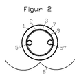
- Querschnitt eines Sydney-Vakuumröhrenkollektors gemäß einer ersten Variante der Erfindung mit einer Zwischenschicht aus GraphitfolieCross section of a Sydney vacuum tube collector according to a first variant of the invention with an intermediate layer of graphite foil
- Figur 3FIG. 3
- Querschnitt eines Sydney-Vakuumröhrenkollektors gemäß einer zweiten Variante der Erfindung mit einem Wärmeüberträgerbauteil aus expandiertem GraphitCross section of a Sydney vacuum tube collector according to a second variant of the invention with a heat transfer member of expanded graphite
- Figur 4FIG. 4
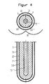
- Quer- und Längsschnitt einer Sydney-Vakuuumröhre gemäß der zweiten Variante der Erfindung mit einem in das Wärmeüberträgerbauteil eingebetteten KoaxialrohrCross and longitudinal section of a Sydney vacuum tube according to the second variant of the invention with a coaxial tube embedded in the heat exchanger component
- Figur 5FIG. 5
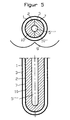
- Quer- und Längsschnitt einer Sydney-Vakuuumröhre gemäß der zweiten Variante der Erfindung mit einer in das Wärmeüberträgerbauteil eingebetteten heatpipeTransverse and longitudinal section of a Sydney vacuum tube according to the second variant of the invention with an embedded in the heat exchanger component heat pipe
- Figur 6FIG. 6
- ein erfindungsgemäßes Wärmeüberträgerbauteil mit abgewandeltem Querschnittan inventive heat exchanger component with a modified cross-section
In den Figuren 2 und 3 werden die beiden prinzipiellen Varianten die Erfindung beispielhaft anhand eines Sydney-Kollektors mit U-förmigem Wärmeträgerrohr 5', 5" dargestellt, sie sind jedoch nicht darauf beschränkt. Alternativ kann die Wärmeträgerflüssigkeit auch durch ein Koaxialrohr oder ein von unten nach oben durchströmtes Rohr geführt werden, oder es wird eine heatpipe benutzt.In Figures 2 and 3, the two basic variants of the invention are exemplified by, but not limited to, a Sydney collector with U-shaped
In einer ersten Variante der Erfindung (Figur 2) wird die Trägerkonstruktion mit den Wärmeträgerrohren an ihrer der Innenwand der Absorberröhre 2 zugewandten Oberfläche mit Graphitfolie umwickelt, welche einen formschlüssigen wärmeleitenden Kontakt zwischen der Absorberröhre 2 und den Wärmeträgerrohren herstellt. Die Trägerkonstruktion selbst ist der Übersicht halber in Figur 2 nicht dargestellt. Wärmeleitbleche werden hier nicht mehr benötigt, so dass das Gewicht der Kollektorröhre vermindert wird.
Aus der Dichtungstechnik ist bekannt, dass Graphitfolie sich leicht an die abzudichtenden Oberflächen anpasst und dadurch Unebenheiten oder andere Unregelmäßigkeiten in der Oberfläche von Flanschen ausgleicht, In der vorliegenden Erfindung passt sich die Graphitfolie 9 genau den anschließenden Oberflächen der Trägerkonstruktion und der Wärmeträgerrohre einerseits und der Innenwand der inneren Glasröhre 2 andererseits an und kompensiert so vorhandene Unregelmäßigkeiten dieser Oberflächen. Dadurch wird der Wärmeübergang erleichtert.
Hinsichtlich der Dicke ist eine Graphitfolie auszuwählen, die einerseits ausreichend reißfest, andererseits ausreichend flexibel ist so dass sie gewickelt werden kann. Geeignete Graphitfolie hat eine Dicke zwischen 0,1 und 1 mm, bevorzugt bis 0,5 mm, und eine Dichte zwischen 0,5 und 1,5 g/cm3.In a first variant of the invention (Figure 2), the support structure is wrapped with the heat transfer tubes on its inner wall of the
From the sealing technique is known that graphite foil adapts easily to the surfaces to be sealed and thereby compensates for bumps or other irregularities in the surface of flanges, In the present invention, the
With regard to the thickness, a graphite foil is to be selected which on the one hand is sufficiently tear-resistant, on the other hand sufficiently flexible so that it can be wound. Suitable graphite foil has a thickness between 0.1 and 1 mm, preferably up to 0.5 mm, and a density between 0.5 and 1.5 g / cm 3 .
In einer weiteren Variante der Erfindung (Figuren 3-5) wird die Trägerkonstruktion aus Wärmeleitblechen, welche die Wärmeträgerrohre aufnimmt, durch ein Formteil aus verpresstem Graphitexpandat substituiert. Dieses wird im folgenden als Wärmeüberträgerbauteil 10 bezeichnet. Die erfindungsgemäßen Wärmeüberträgerbauteile 10 haben eine im wesentlichen zylindrische Gestalt mit Aussparungen für die Aufnahme der Wärmeträgerrohre. Das Wärmeüberträgesbauteil 10 ist so dimensioniert, dass sich seine Umfangsfläche zumindest teilweise formschlüssig an die Innenwand der inneren Glasröhre 2 (Absorberröhre) anschließt. Die Wärmeträgerrohre, in Figur 3 beispielhaft als U-Rohr 5', 5" dargestellt, wiederum werden formschlüssig von dem Wärmeüberträgerbauteil 10 aus verpresstem Graphitexpandat aufgenommen.
Das Wärmeüberträgerbauteil 10 kann als einstückiges Formteil ausgebildet sein, aus fertigungstechnischen Gründen ist es jedoch, wie in den Figuren 3-5 dargestellt, bevorzugt aus zwei Halbformteilen 10' und 10" zusammengesetzt.In a further variant of the invention (FIGS. 3-5), the support structure made of heat-conducting sheets, which accommodates the heat-transfer tubes, is substituted by a molded part made of pressed graphite expandate. This is referred to below as the
The
Die folgenden Figuren zeigen dieselbe Variante der Erfindung mit anderen Arten von Wärmeträgerrohren.
Figur 4 zeigt im Quer und Längsschnitt eine doppelwandige Glasröhre 1, 2, in welcher die Wärmeträgerflüssigkeit durch ein Koaxialrohr 5''' geführt wird. Das Kaxialrohr ist zwischen den beiden Halbformteilen 10', 10", deren aneinander stoßende Oberflächen entsprechende Aussparungen aufweisen, formschlüssig eingebettet.
Figur 5 zeigt als weitere Alternative im Quer- und Längsschnitt eine doppelwandige Glasröhre 1, 2, in welcher die Wärmeträgerflüssigkeit durch eine heat-pipe 5'''' geführt wird. Die heat-pipe ist zwischen den beiden Halbformteilen 10', 10'', deren aneinander stoßende Oberflächen entsprechende Aussparungen aufweisen, formschlüssig eingebettet.
Ebenso kann ein von unten nach oben durchströmtes Wärmeträgerrohr formschlüssig zwischen den beiden das Wärmeträgerbauelement 10 bildenden Halbformteilen 10', 10" eingebettet werden, oder Kombinationen von verschiedenartigen Wärmeträgerrohren.The following figures show the same variant of the invention with other types of heat transfer tubes.
Figure 4 shows in transverse and longitudinal section a double-
Figure 5 shows a further alternative in transverse and longitudinal section a double-
Likewise, a through-flow from bottom to bottom heat transfer tube between the two the
Da Graphitexpandat sich durch eine hohe Anpassungsfähigkeit an benachbarte Oberflächen auszeichnet, ist ein formschlüssiger Verbund und damit ein geringer Wärmeübergangswiderstand zur Innenwand der inneren Glasröhre 2 einerseits und zu den Wärmeträgerrohren andererseits gewährleistet, Dadurch wird der Wärmeübergang erleichtert, und der Wärmeübergangswiderstand sinkt.
Außerdem wird durch den Formschluss des Wärmeüberträgerbauteils 10 mit der inneren Glasröhre 2 und den Wärmeträgerrohren die Stabilität des gesamten Aufbaus der Vakuumröhre erhöht.
Darüber hinaus eliminiert dieser erfindungsgemäße Aufbau das Problem der unterschiedlichen thermischen Ausdehnungen von Kupfer und Aluminium. Das Wärmeüberträgerbauteil 10 aus verpresstem Graphitexpandat besitzt aufgrund seiner Porosität eine Kompressionsreserve, so dass die thermische Ausdehnung des Kupferrohrs kompensiert werden kann, Ein weiterer Vorteil dieser Variante der Erfindung besteht in der Gewichtsreduzierung, da das Formteil 10 aus verpresstem Graphitexpandat wesentlich leichter ist als die herkömmliche metallische Trägerkonstruktion.Since Graphitexpandat is characterized by a high adaptability to adjacent surfaces, a positive bond and thus a low heat transfer resistance to the inner wall of the
In addition, the stability of the entire construction of the vacuum tube is increased by the positive connection of the
In addition, this structure of the invention eliminates the problem of different thermal expansion of copper and aluminum. The heat exchanger component A further advantage of this variant of the invention is the weight reduction, since the molded
Die Herstellung von Graphitexpandat und Graphitfolie ist bekannt. Graphiteinlagerungsverbindungen (Graphitsalze), z.B. Graphithydrogensulfat oder Graphitnitrat, werden schockartig in einem Ofen oder mittels Mikrowellen erhitzt. Dabei vergrößert sich das Volumen der Partikel um den Faktor 200 bis 400, und die Schüttdichte sinkt auf 2 bis 20 g/l. Das so erhaltene Graphitexpandat besteht aus wurm- oder ziehharnionikaförmigen Aggregaten. Bei Verdichtung verhaken sich die einzelnen Aggregate untereinander zu einem festen Verbund, so dass ohne Binderzusatz selbsttragende Flächengebilde, zB. Folien oder Bahnen, oder Formkörper, z.B. Platten, hergestellt werden können.
Eine weitere aus dem Stand der Technik bekannte Methode zur Herstellung von dreidimensionalen Formkörpern aus Graphitexpandat besteht darin, die thermische Expansion der Graphiteinlagerungsverbindung bzw. des Graphitsalzes in einem entsprechend ausgelegten Formwerkzeug durchzuführen. Dabei ist zu beachtea, dass das Formwerkzeug das Entweichen von Gasen zulassen muss. Wegen der aufwändigea Werkzeugauslegung ist diese Methode für die Herstellung der Formteile für die vorliegenden Erfindung jedoch nicht bevorzugt.
Stattdessen hat sich eine Methode bewährt, nach der zunächst Graphitexpandat in bekannter Weise zu einer Platte passender Dicke, typischerweise zwischen 5 und 50 mm, verpresst wird und aus dieser Platte Rohlinge ausgeschnitten werden, welche dann in einem Werkzeug in die gewünschte Form gepresst werden. Die im wesentlichen zylinderförmigen Formteile können einstückig sein oder durch Aneinanderlegen von zwei einzeln nach dieser Methode gefertigten halbzylindrischen Formteilen gebildet werden.
Die Dichte des Graphitexpandats in diesen Formteilen liegt im Bereich zwischen 0,02 und 0,5 g/cm3.
Alternativ können die Formteile auch durch Formextcudieren aus vorgefertigten Platten hergestellt werden.
Soll das Wärmeüberträgerbauteil in eine bereits mit Wärmeträgerrohren versehene Vakuumröhre eingesetzt werden, so müssen im Formteil Aussparungen für die Aufnahme der Wärmeträgerrohre oder der heat-pipe vorgesehen werden. Dank der leichten Bearbeitbarkeit von Presslingen aus Graphitexpandat lassen die Aussparungen sich ohne Schwierigkeiten in das Formteil einpressen oder aus ihm herausschneiden. Das Formteil wird anschließend von deren offenem Ende aus in die Vakuumröhre hinein geschoben, wobei die Wärmeträgerrohre in die dafür vorgesehenen Aussparungen gleiten.
In einer anderen Ausführungsform der Erfindung wird ein komplettes Bauteil hergestellt umfassend das Wärmeträgerrohr und das aus Graphitexpandat gepresste Wärmeträgerbauteil. Dazu wird das Wärmeträgerrohr einfach in das Formteil, das ggf. aus zwei aneinander gelegten Halbformteilen besteht, hinein gepresst bzw. zwischen den beiden Halbformteilen eingebettet, so dass es formschlüssig aufgenommen wird.
Mit einem zylindrischen Wärmeüberträgerbauteil, das an seinem gesamten Umfang den Innenabmessungen der Absorberröhre 2 entspricht, wird die Erfindung optimal verwirklicht wegen des vollflächigen Formschlusses über die gesamte verfügbare Innenwandfläche der Absorberröhre 2. Grundsätzlich sind auch Abweichungen von der zylindrischen Form denkbar, beispielsweise durch Aussparungen oder Einbuchtungen am runden Querschnitt des Zylinders. In diesen Bereichen besteht dann kein Formschluss zur Innenwand der Absorberröhre, der vollflächige Formschluss ist auf die Berührungsflächen des Wärmeüberträgerbauteils 10 mit der Innenwand der Absorberröhre 2 begrenzt. Letztendlich hängt es vom konkreten Anwendungsfall ab und ist vom Fachmann zu entscheiden, welcher Querschnitt des Wärmeüberträgerbauteils 10 gewählt wird, wobei die Wirkungsgradverluste bei verringerter Berührungsfläche zwischen Wärmeträgerbauteil 10 und Absorberröhre 2 einerseits und die durch Abweichungen von der Zylinderform andererseits möglichen Materialeinsparungen in Betracht zu ziehen sind.
Da also Abweichungen von der Zylinderform möglich sind, sollen im Sinne dieser Erfindung unter "im wesentlichen zylinderförmig" Formteile verstanden werden mit einer Geometrie, die man als von einem Zylinder abgeleitet betrachten kann, derart, dass sein ursprünglich runder Querschnitt mit Einbuchtungen oder Aussparungen versehen ist, so dass die Umfangsfläche dieses Gebildes nur noch in begrenzten Bereichen der Umfangsfläche eines Zylinders entspricht. Diese Bereiche bilden die Berührungsflächen zwischen dem Wärmeleitelement 10 und der Innenwand der inneren Glasröhre 2, und an diesen Berührungsflächen ist der Fonnschluss vollflächig.
Ein Beispiel für eine solche von der Zylinderform abweichende Gestalt des Formteils 10, hier mit eingebettetem Koaxialrohr 5''', zeigt Figur 6. Der formschlüssige Kontakt zur Absorberröhre 2 (die äußere Röhre 1 wurde der Einfachheit halber in der Darstellung weggelassen) beschränkt sich auf die Berührungsflächen 11, ist in diesen Bereichen jedoch aufgrund der hohen Anpassungsfähigkeit des verpressten Graphitexpandats nahezu vollflächig.The production of graphite expandate and graphite foil is known. Graphite intercalation compounds (graphite salts), for example graphite hydrogen sulfate or graphite nitrate, are shock-heated in an oven or by means of microwaves. The volume of the particles increases by a factor of 200 to 400, and the bulk density drops to 2 to 20 g / l. The resulting graphite expandate consists of worm or ziehharnionika-shaped aggregates. When compacting the individual units interlock with each other to form a solid composite, so that without binder additive self-supporting fabrics, eg. Films or webs, or shaped articles, such as plates can be produced.
Another known from the prior art method for the production of three-dimensional moldings of Graphitexpandat is to perform the thermal expansion of Graphiteinlagerungsverbindung or the graphite salt in a suitably designed mold. It should be noted that the mold must allow the escape of gases. However, because of the elaborate tool design, this method is not preferred for the production of moldings for the present invention.
Instead, a method has been proven, according to the first graphite expander in a known manner to a plate of appropriate thickness, typically between 5 and 50 mm, is pressed and cut out of this plate blanks, which are then pressed in a tool in the desired shape. The substantially cylindrical shaped parts may be in one piece or formed by juxtaposing two semi-cylindrical shaped parts produced individually by this method.
The density of the graphite expandate in these moldings ranges between 0.02 and 0.5 g / cm 3 .
Alternatively, the moldings can also be made by form extracting from prefabricated panels.
If the heat exchanger component to be used in an already provided with heat transfer tubes vacuum tube, so must be provided in the molding recesses for receiving the heat transfer tubes or the heat pipe. Thanks to the easy workability of pressed pieces of expanded graphite, the recesses can be pressed into the molded part without difficulty or cut out of it. The molded part is then pushed from the open end into the vacuum tube, wherein the heat transfer tubes slide into the recesses provided for this purpose.
In another embodiment of the invention, a complete component is produced, comprising the heat carrier tube and the heat transfer medium component pressed from expanded graphite. For this purpose, the heat transfer tube is simply pressed into the molding, which may consist of two juxtaposed half moldings, or embedded between the two half moldings, so that it is received positively.
With a cylindrical heat exchanger component, which corresponds to the inner dimensions of the
Since deviations from the cylindrical shape are therefore possible, for the purposes of this invention "substantially cylindrical" shaped parts are to be understood as having a geometry that can be regarded as derived from a cylinder such that its originally round cross section is provided with indentations or recesses , so that the peripheral surface of this structure corresponds only in limited areas of the peripheral surface of a cylinder. These areas form the contact surfaces between the heat-conducting
An example of such a deviating from the cylindrical shape shape of the
Die beiden erfindungsgemäßen Varianten gemäß Figur 2 und 3 - Graphitfolie 9 an der Innenseite der Absorberröhre 2 und Aufnahme der Wärmeträgerrohre in einem Formteil 10 aus verpresstem Graphitexpandat - können auch kombiniert werden, so dass die Wärmeträger-, rohre durch ein Formteil aus Graphitexpandat 10 aufgenommen werden, das seinerseits mit Graphitfolie 9 umwickelt ist.The two variants according to the invention according to FIGS. 2 and 3 -
In einer weiteren Variante der Erfindung wird anstelle der dem Vakuumspalt zugewandten Oberfläche der inneren Glasröhre 2 die der Innenwand der inneren Glasröhre 2 zugewandte Oberfläche des Wärmeüberträgerbauteils 10 mit einer Absorberschicht versehen. Diese Variante hat den Vorteil, dass der Wärmeübergang durch die Glaswand der Röhre 2 entfällt.In a further variant of the invention, instead of the surface of the
Für den Einsatz in Gegenden mit starker Sonneneinstrahlung, z.B. in südeuropäischen oder afrikanischen Ländern kann auch völlig auf die Absorptionsschicht 7 verzichtet und die Absorptionswirkung des Graphits genutzt werden. Damit verbundene Wirkungsgradeinbußen werden durch Einsparungen bei den Material- und Herstellungskosten kompensiert, was den Einsatz auch in ärmeren Ländern, von denen sich viele in Erdteilen mit starker Sonneneinstrahlung befinden, begünstigt.For use in areas of strong sunlight, e.g. in southern European or African countries, the
Claims (16)
dadurch gekennzeichnet, dass
in der inneren Glasröhre (2) ein Wärmeleitelement (9, 10) aus verpresstem Graphitexpandat angeordnet ist mit vollflächigem Formschluss einerseits an den Berührungsflächen des Wärmeleitelements mit der Innenwand der inneren Glasröhre (2) und andererseits zu den Wärmeträgerrohren (5', 5'', 5''', 5''') bzw. einer die Wärmeträgerrohre (5', 5'', 5''', 5''') aufnehmenden Trägerkonstruktion (4).Solar collector vacuum tube of two concentric nested glass tubes (1, 2), each hemispherical closed at one end and fused together at the other end, wherein the gap (3) between the glass tubes (1) and (2) is evacuated, with at least one tube (5 ', 5'',5''', 5 ''') through which a heat transfer medium flows in the interior of the inner glass tube (2) and optionally an absorber layer (7) on the surface of the vacuum gap (3) inner glass tube (2),
characterized in that
in the inner glass tube (2) a Wärmeleitelement (9, 10) of compressed graphite expanate is arranged with full-surface fit on the one hand at the contact surfaces of the Wärmeleitelements with the inner wall of the inner glass tube (2) and on the other hand to the heat transfer tubes (5 ', 5'', 5 ''',5''') or one of the heat transfer tubes (5 ', 5'',5''', 5 ''') receiving support structure (4).
die vom Wärmeträgermedium durchströmten Rohre als U-förmige (5', 5''), als von unten nach oben durchströmte, als koxiale Wärmeträgerrohre (5''') oder heat-pipes (5'''') oder Kombinationen davon ausgebildet sind.Solar collector vacuum tube according to claim, characterized in that
the tubes through which the heat transfer medium flows are designed as U-shaped (5 ', 5'') as from bottom to top, as koxiale heat transfer tubes (5''') or heat pipes (5 '''') or combinations thereof ,
das Wärmeleitelement durch Graphitfolie (9) gebildet wird, die um die die Wärmeträgerrohre (5', 5", 5''', 5"") aufnehmende Trägerkonstruktion (4) gewickelt ist und formschlüssig an die Innenwand der inneren Glasröhre (2) anschließt.Solar collector vacuum tube according to claim 1, characterized in that
the heat-conducting element is formed by graphite foil (9), which is wound around the support structure (4) accommodating the heat transfer tubes (5 ', 5 ", 5''',5"') and positively connecting to the inner wall of the inner glass tube (2) ,
die Graphitfolie (9) eine Dicke zwischen 0,1 und 1 mm und eine Dichte zwischen 0,5 und 1,5 g/cm3 aufweist.Solar collector vacuum tube according to claim 3, characterized in that
the graphite foil (9) has a thickness between 0.1 and 1 mm and a density between 0.5 and 1.5 g / cm 3 .
die Wärmeträgerrohre (5', 5", 5''', 5'''') formschlüssig von einem Wärmeträgerbauteil (10) aus verpresstem Graphitexpandat aufgenommen werden, an dessen Berührungsflächen mit der Innenwand der inneren Glasröhre (2) ein fonnschlüssiger Verbund zwischen dem Wäriaeleitelement (10) und der Innenwand der inneren Glasröhre (2) vorliegt.Solar collector vacuum tube according to claim 1, characterized in that
the heat transfer tubes (5 ', 5 ", 5''', 5 '''') are positively received by a heat transfer member (10) of compressed graphite expander, at its contact surfaces with the inner wall of the inner glass tube (2) a fonnschlüssiger composite between the Wäriaeleitelement (10) and the inner wall of the inner glass tube (2) is present.
das Wärmeüberträgerbauteil (10) aus zwei Halbformteilen (10', 10") zusammengesetzt ist.Solar collector vacuum tube according to claim 5, characterized in that
the heat exchanger component (10) is composed of two half-molded parts (10 ', 10 ").
die Dichte des Graphitexpandats im Wärmeüberträgerbauteil (10) zwischen 0,02 und 0,5 g/cm3 liegt.Solar collector vacuum tube according to claim 5, characterized in that
the density of the graphite expander in the heat exchanger component (10) is between 0.02 and 0.5 g / cm 3 .
die der Innenwand der inneren Glasröhre (2) zugewandte Oberfläche des Wärmeüberträgerbauteils (10) mit einer Absorberschicht versehen ist.Solar collector vacuum tube according to claim 5, characterized in that
the surface of the heat exchanger component (10) facing the inner wall of the inner glass tube (2) is provided with an absorber layer.
die Wärmeträgerrohre (5', 5'', 5''', 5'''') formschlüssig von einem Wärmeüberträgerbauteil (10) aus verpresstem Graphitexpandat aufgenommen werden, das mit Graphitfolie (9) umwickelt ist, die sich formschlüssig an die Innenwand der inneren Glasröhre (2) anschließt.Solar collector vacuum tube according to claim 1, characterized in that
the heat transfer tubes (5 ', 5'',5''', 5 '''') are positively received by a heat transfer member (10) of compressed graphite expander, which is wrapped with graphite foil (9), which is positively connected to the inner wall of the inner glass tube (2) connects.
in dem Formteil (10) aus verpresstem Graphitexpandat Aussparungen für die formschlüssige Aufnahme der Wätmeträgerrohre (5', 5'',5''',5'''') vorgesehen sind.Heat exchanger component according to claim 11, characterized in that
in the molded part (10) of compressed graphite expander recesses for the positive reception of the heat transfer tubes (5 ', 5'',5''', 5 '''') are provided.
in dem Formteil (10) aus verpresstem Graphitexpandat Wärmeträgerrohre (5', 5'',5''',5'''') formschlüssig eingebettet sind.Heat exchanger component according to claim 11, characterized in that
in the molded part (10) of compressed graphite expander heat transfer tubes (5 ', 5'',5''', 5 '''') are positively embedded.
das Formteil (10) aus zwei Halbformteilen (10', 10'') zusammengesetzt ist.Heat exchanger component according to claim 11, characterized in that
the molded part (10) is composed of two half-molded parts (10 ', 10'').
die Dichte des Graphitexpandats im Formteil (10) zwischen 0,02 und 0,5 g/cm3.Heat exchanger component according to claim 11, characterized in that
the density of the graphite expandate in the molded part (10) is between 0.02 and 0.5 g / cm 3 .
die der Innenwand der inneren Glasröhre (2) zugewandte Oberfläche des Wärmeüberträgerbauteils (10) mit einer Absorberschicht versehen istHeat exchanger component according to claim 11, characterized in that
the surface of the heat exchanger component (10) facing the inner wall of the inner glass tube (2) is provided with an absorber layer
Priority Applications (6)
| Application Number | Priority Date | Filing Date | Title |
|---|---|---|---|
| EP05013591A EP1736715A1 (en) | 2005-06-23 | 2005-06-23 | Vacuum tube for solar collectors with improved heat transfer |
| KR1020087001756A KR20080031308A (en) | 2005-06-23 | 2006-05-16 | Vacuum tubes for solar collectors with improved heat transfer |
| JP2008517345A JP2008544206A (en) | 2005-06-23 | 2006-05-16 | Vacuum tubes used in solar collectors with improved heat transfer |
| PCT/EP2006/004602 WO2006136243A1 (en) | 2005-06-23 | 2006-05-16 | Vacuum tubes for solar collectors having improved heat transfer |
| CNA200680021135XA CN101198827A (en) | 2005-06-23 | 2006-05-16 | Vacuum tube for solar collectors with improved heat transfer |
| US11/964,291 US20080156314A1 (en) | 2005-06-23 | 2007-12-26 | Vacuum tubes for solar collectors with improved heat transfer |
Applications Claiming Priority (1)
| Application Number | Priority Date | Filing Date | Title |
|---|---|---|---|
| EP05013591A EP1736715A1 (en) | 2005-06-23 | 2005-06-23 | Vacuum tube for solar collectors with improved heat transfer |
Publications (1)
| Publication Number | Publication Date |
|---|---|
| EP1736715A1 true EP1736715A1 (en) | 2006-12-27 |
Family
ID=35456069
Family Applications (1)
| Application Number | Title | Priority Date | Filing Date |
|---|---|---|---|
| EP05013591A Withdrawn EP1736715A1 (en) | 2005-06-23 | 2005-06-23 | Vacuum tube for solar collectors with improved heat transfer |
Country Status (6)
| Country | Link |
|---|---|
| US (1) | US20080156314A1 (en) |
| EP (1) | EP1736715A1 (en) |
| JP (1) | JP2008544206A (en) |
| KR (1) | KR20080031308A (en) |
| CN (1) | CN101198827A (en) |
| WO (1) | WO2006136243A1 (en) |
Cited By (7)
| Publication number | Priority date | Publication date | Assignee | Title |
|---|---|---|---|---|
| FR2919712A1 (en) * | 2007-08-02 | 2009-02-06 | Claude Alix Georges Pomero | Thermal solar sensor for heating e.g. dwelling, has transparent cylinder with elliptical section closed at its ends by covers, where cylinder contains colored liquid and copper tubes permitting circulation of water to be heated |
| DE102008051905A1 (en) * | 2008-10-16 | 2010-07-15 | Sgl Carbon Se | Process for the production of heat exchanger tubes |
| CN101813394A (en) * | 2010-04-04 | 2010-08-25 | 姚德龙 | High thermal conductive fin for heat collector of solar water heater |
| CN101581508B (en) * | 2009-06-29 | 2011-01-26 | 浙江高得乐新能源有限公司 | Solar evacuated collector tube provided with heat accelerator |
| CN103363689A (en) * | 2013-08-09 | 2013-10-23 | 吴健 | Heat pipe type solar thermal collector using solid media to exchange heat |
| EP2733438A1 (en) * | 2012-11-19 | 2014-05-21 | Viessmann Werke GmbH & Co. KG | Solar collector |
| EP2827078A1 (en) * | 2013-07-17 | 2015-01-21 | Urs Furter | Solar heat collector for heating a circulating fluid and process for manufacturing a solar heat collector |
Families Citing this family (21)
| Publication number | Priority date | Publication date | Assignee | Title |
|---|---|---|---|---|
| SK842007A3 (en) * | 2007-06-19 | 2009-01-07 | Schener S. R. O. | Absorber of solar vacuum tube |
| US7971587B2 (en) | 2007-10-31 | 2011-07-05 | The Regents Of The University Of California | Apparatus and method for solar thermal energy collection |
| CN101387447B (en) * | 2008-10-08 | 2010-06-09 | 大连理工大学 | Graphite-filled vacuum glass tube closed-loop capillary pipe solar thermal-collecting tube |
| CN101387449B (en) * | 2008-10-08 | 2010-06-02 | 大连理工大学 | Graphite-filled vacuum glass tube open type capillary pipe solar thermal-collecting tube |
| KR101030691B1 (en) * | 2008-12-05 | 2011-04-27 | (주)해빛에너지 | Heat transfer plate for solar heat collector using vacuum tubes |
| FR2942030B1 (en) * | 2009-02-12 | 2012-10-19 | Sophia Antipolis En Dev | SET OF CALODUCKS FOR SOLAR SENSORS |
| CA2672760C (en) * | 2009-07-23 | 2017-10-17 | Huazi Lin | Solar coffee/tea maker and cooking appliances |
| CA2673703C (en) * | 2009-07-23 | 2015-05-05 | Huazi Lin | Solar cooking appliances |
| SE534515C2 (en) * | 2009-12-09 | 2011-09-20 | Climatewell Ab Publ | Thermal solar collector with built-in chemical heat pump |
| JP2012002484A (en) * | 2010-06-21 | 2012-01-05 | Daiwa House Industry Co Ltd | Solar heat collection panel structure |
| KR101155691B1 (en) * | 2010-07-19 | 2012-06-12 | 주식회사 써너지 | Vacuum tube type solar energy collecting pipe |
| KR101002413B1 (en) | 2010-07-21 | 2010-12-17 | 삼신설계(주) | Solar collector system using a transfer technique of water and solar heat energy |
| US20120073567A1 (en) * | 2010-09-23 | 2012-03-29 | Roland Winston | Solar thermal concentrator apparatus, system, and method |
| FR3034506B1 (en) | 2015-03-31 | 2017-05-05 | Commissariat Energie Atomique | MULTI-ELEMENT THERMAL CONDUCTOR FOR VACUUM TUBE OF A THERMAL SOLAR SENSOR WITH DUAL VACUUM TUBES |
| WO2017002127A1 (en) * | 2015-06-27 | 2017-01-05 | Indian Institute Of Technology Bombay | Solar collector with absorber integrated heat storage |
| WO2017210674A1 (en) * | 2016-06-03 | 2017-12-07 | The Trustees Of Columbia University In The City Of New York | Tankless solar water heater using bottomless vacuum tubes |
| KR101924418B1 (en) | 2016-09-27 | 2019-02-20 | 강민수 | Solar collectors and condensing |
| IT201700109097A1 (en) * | 2017-09-28 | 2019-03-28 | Archimede Sistemi Ind S R L S | SOLAR ENERGY CONVERTER DEVICE, CORRESPONDING SOLAR REACTOR, AND ITS RELATIVE SYSTEM |
| US11519655B2 (en) | 2020-07-31 | 2022-12-06 | Photon Vault, Llc | Thermal energy storage and retrieval systems and methods |
| US11428476B2 (en) | 2020-09-04 | 2022-08-30 | Photon Vault, Llc | Thermal energy storage and retrieval system |
| US20220146151A1 (en) * | 2020-11-09 | 2022-05-12 | Photon Vault, Llc | Multi-temperature heat collection system |
Citations (16)
| Publication number | Priority date | Publication date | Assignee | Title |
|---|---|---|---|---|
| US4031862A (en) * | 1976-03-10 | 1977-06-28 | Smith Frank J | Economizer |
| FR2365761A1 (en) * | 1976-09-27 | 1978-04-21 | Gen Electric | SOLAR COLLECTOR |
| FR2444238A1 (en) * | 1978-12-12 | 1980-07-11 | Lampes Sa | Heat transfer element for solar heating panel - has S=shaped metal inside vacuum double-walled tube to hold two heat conducting fluid pipes |
| US4432408A (en) * | 1982-07-19 | 1984-02-21 | The Dow Chemical Co. | Method and compressed vermicular expanded graphite apparatus for heat exchanging |
| US4440156A (en) * | 1981-07-06 | 1984-04-03 | Nitto Kohki Co., Ltd. | Solar heat collector |
| JPS6122572A (en) * | 1984-07-09 | 1986-01-31 | Hitachi Ltd | Fuel cell |
| FR2600073A1 (en) * | 1986-06-16 | 1987-12-18 | Lorraine Carbone | Thermal contact with high transfer coefficient and applications |
| FR2610088A1 (en) * | 1987-01-23 | 1988-07-29 | Lorraine Carbone | Device for cooling a structure subjected to an intense heat flux and method of producing this device |
| EP0458150A1 (en) * | 1990-05-24 | 1991-11-27 | Bayer Ag | Process for producing shaped articles |
| EP0515891A1 (en) * | 1991-05-25 | 1992-12-02 | Bayer Ag | Process for producing mouldings from expanded graphite |
| DE29819832U1 (en) * | 1998-02-28 | 1999-01-28 | Thermomax Ltd., Bangor | Vacuum solar collector with reflector |
| DE10022972A1 (en) * | 2000-05-11 | 2001-11-22 | Bosch Gmbh Robert | Micro heat exchanger has a number of parallel metal hollow fiber tubes shrouded by a graphite matrix body for a high heat exchange in a simple unit |
| WO2003057475A1 (en) * | 2001-12-26 | 2003-07-17 | Graftech Inc. | Improved thermal interface material |
| WO2004094924A2 (en) * | 2003-04-22 | 2004-11-04 | Solargenix Energy Llc | Solar collectors with evacuated receiver and nonimaging external reflectors |
| EP1512933A2 (en) * | 2003-09-04 | 2005-03-09 | Sgl Carbon Ag | Heat conduction plate made of expanded graphite and method of fabrication thereof |
| FR2860512A1 (en) * | 2003-10-06 | 2005-04-08 | Silva Serge Da | METHOD FOR MANUFACTURING COMPOSITE OBJECTS USING EXPANDED GRAPHITE AND VERMICULITE |
Family Cites Families (58)
| Publication number | Priority date | Publication date | Assignee | Title |
|---|---|---|---|---|
| US915059A (en) * | 1908-06-17 | 1909-03-09 | Dennis O Brien | Protective covering for blow-off pipes of steam-boilers and the like. |
| US980505A (en) * | 1909-06-01 | 1911-01-03 | Gen Electric | Apparatus for utilizing solar heat. |
| US1345758A (en) * | 1919-02-14 | 1920-07-06 | Arthur V Folsom | Solar steam-generator |
| US1871508A (en) * | 1930-07-02 | 1932-08-16 | Henry A Gardner | Metallic conduit |
| US1989999A (en) * | 1933-06-07 | 1935-02-05 | Niederle Max | Solar water heater |
| US2205378A (en) * | 1938-03-12 | 1940-06-25 | Abbot Charles Greeley | Solar flash boiler |
| US2247830A (en) * | 1938-07-07 | 1941-07-01 | Charles G Abbot | Solar heater |
| US2460482A (en) * | 1945-02-20 | 1949-02-01 | Abbot Charles Greeley | Solar heat collector |
| US2856905A (en) * | 1955-04-04 | 1958-10-21 | Oxy Catalyst Inc | Heat generating and exchanging device |
| GB991581A (en) * | 1962-03-21 | 1965-05-12 | High Temperature Materials Inc | Expanded pyrolytic graphite and process for producing the same |
| US3323869A (en) * | 1963-12-19 | 1967-06-06 | Dow Chemical Co | Process for producing expanded graphite |
| US3322979A (en) * | 1964-03-31 | 1967-05-30 | Texas Instruments Inc | Thermionic energy converter |
| US3265124A (en) * | 1964-07-10 | 1966-08-09 | Falls Ind Inc | Coated graphite products |
| US3379394A (en) * | 1964-10-27 | 1968-04-23 | Navy Usa | Optical solar energy converter |
| US3327777A (en) * | 1964-11-09 | 1967-06-27 | Union Carbide Corp | Heat interchanger |
| US3389964A (en) * | 1966-04-04 | 1968-06-25 | Dow Chemical Co | Process for preparing low density graphite structrues |
| US3815574A (en) * | 1973-06-01 | 1974-06-11 | G Gaydos | Solar heating system |
| US4099514A (en) * | 1974-01-07 | 1978-07-11 | Mario Posnansky | Method and apparatus for heating a fluid medium by means of solar energy |
| US3952724A (en) * | 1974-06-24 | 1976-04-27 | Owens-Illinois, Inc. | Solar energy converter |
| US3914100A (en) * | 1974-07-29 | 1975-10-21 | Wheeling Pittsburgh Steel Corp | Pipe protective covering |
| US3964929A (en) * | 1975-07-21 | 1976-06-22 | United Technologies Corporation | Fuel cell cooling system with shunt current protection |
| US4067315A (en) * | 1975-10-24 | 1978-01-10 | Corning Glass Works | Solar heat pipe |
| US4120285A (en) * | 1976-11-01 | 1978-10-17 | Owens-Illinois, Inc. | Modular tubular solar energy collector apparatus |
| US4186724A (en) * | 1976-11-22 | 1980-02-05 | American Solar | Solar energy collector |
| US4153039A (en) * | 1977-01-07 | 1979-05-08 | Carroll John H | Focusing solar energy apparatus |
| US4233957A (en) * | 1978-02-16 | 1980-11-18 | Corning Glass Works | Solar energy collector |
| US4199628A (en) * | 1978-03-23 | 1980-04-22 | The Dow Chemical Company | Vermicular expanded graphite composite material |
| US4265952A (en) * | 1978-03-23 | 1981-05-05 | The Dow Chemical Company | Vermicular expanded graphite composite material |
| US4304267A (en) * | 1978-10-12 | 1981-12-08 | Campbell Frank Jun | Interlocking refractory for covering a pipe |
| US4355684A (en) * | 1979-06-13 | 1982-10-26 | The Dow Chemical Company | Uniaxially compressed vermicular expanded graphite for heat exchanging |
| US4349013A (en) * | 1979-06-25 | 1982-09-14 | Alpha Solarco Inc. | Solar energy receivers |
| US4250958A (en) * | 1979-07-16 | 1981-02-17 | Wasserman Kurt J | Double tubular thermal energy storage element |
| CA1161324A (en) * | 1979-08-29 | 1984-01-31 | Jacques M. Hanlet | Electromagnetic energy absorber |
| US4259946A (en) * | 1979-10-22 | 1981-04-07 | Thermacore, Inc. | Solar collector |
| US4233369A (en) * | 1979-10-29 | 1980-11-11 | United Technologies Corporation | Fuel cell cooler assembly and edge seal means therefor |
| US4340035A (en) * | 1980-04-24 | 1982-07-20 | Begun James A | Solar collector |
| US4324844A (en) * | 1980-04-28 | 1982-04-13 | Westinghouse Electric Corp. | Variable area fuel cell cooling |
| JPS5838708B2 (en) * | 1981-03-06 | 1983-08-24 | 工業技術院長 | solar heat collector |
| JPS5844284Y2 (en) * | 1981-07-06 | 1983-10-07 | 日東工器株式会社 | Vacuum double tube solar collector tube |
| US4471837A (en) * | 1981-12-28 | 1984-09-18 | Aavid Engineering, Inc. | Graphite heat-sink mountings |
| US4945010A (en) * | 1983-06-02 | 1990-07-31 | Engelhard Corporation | Cooling assembly for fuel cells |
| US4520795A (en) * | 1983-12-09 | 1985-06-04 | Parkyn William A | Solar collector having tank and glazing construction |
| JPH0328267Y2 (en) * | 1986-05-30 | 1991-06-18 | ||
| JPS6343045U (en) * | 1986-09-06 | 1988-03-22 | ||
| US4776790A (en) * | 1986-12-22 | 1988-10-11 | Norton Company | Refractory shields for curved and straight superheater tubes |
| US4993403A (en) * | 1988-03-11 | 1991-02-19 | Downs Charles W | Method and apparatus for trapping heat energy |
| JP2620606B2 (en) * | 1990-05-16 | 1997-06-18 | 東洋炭素株式会社 | High purity flexible expanded graphite sheet and method for producing the same |
| US5074283A (en) * | 1990-08-10 | 1991-12-24 | The United States Department Of Energy | Thermal storage module for solar dynamic receivers |
| JPH0519861U (en) * | 1991-08-21 | 1993-03-12 | シロキ工業株式会社 | Vacuum double heat collecting tube in solar water heater |
| JP3087929B2 (en) * | 1992-10-26 | 2000-09-18 | 日本電気硝子株式会社 | Vacuum solar collector |
| US5523260A (en) * | 1993-08-02 | 1996-06-04 | Motorola, Inc. | Method for heatsinking a controlled collapse chip connection device |
| JPH07324826A (en) * | 1994-05-30 | 1995-12-12 | Shiroki Corp | Vacuum duplex glass tube |
| US5724923A (en) * | 1995-05-19 | 1998-03-10 | Saint-Gobain/Norton Industrial Ceramics Corp. | Refractory shield design for superheater tubes |
| US6503626B1 (en) * | 2000-02-25 | 2003-01-07 | Graftech Inc. | Graphite-based heat sink |
| US6538892B2 (en) * | 2001-05-02 | 2003-03-25 | Graftech Inc. | Radial finned heat sink |
| US6619283B2 (en) * | 2001-09-11 | 2003-09-16 | Manu Ghela | Solar collector pipe |
| US6771502B2 (en) * | 2002-06-28 | 2004-08-03 | Advanced Energy Technology Inc. | Heat sink made from longer and shorter graphite sheets |
| US20070158050A1 (en) * | 2006-01-06 | 2007-07-12 | Julian Norley | Microchannel heat sink manufactured from graphite materials |
-
2005
- 2005-06-23 EP EP05013591A patent/EP1736715A1/en not_active Withdrawn
-
2006
- 2006-05-16 CN CNA200680021135XA patent/CN101198827A/en active Pending
- 2006-05-16 JP JP2008517345A patent/JP2008544206A/en active Pending
- 2006-05-16 WO PCT/EP2006/004602 patent/WO2006136243A1/en active Application Filing
- 2006-05-16 KR KR1020087001756A patent/KR20080031308A/en not_active Application Discontinuation
-
2007
- 2007-12-26 US US11/964,291 patent/US20080156314A1/en not_active Abandoned
Patent Citations (16)
| Publication number | Priority date | Publication date | Assignee | Title |
|---|---|---|---|---|
| US4031862A (en) * | 1976-03-10 | 1977-06-28 | Smith Frank J | Economizer |
| FR2365761A1 (en) * | 1976-09-27 | 1978-04-21 | Gen Electric | SOLAR COLLECTOR |
| FR2444238A1 (en) * | 1978-12-12 | 1980-07-11 | Lampes Sa | Heat transfer element for solar heating panel - has S=shaped metal inside vacuum double-walled tube to hold two heat conducting fluid pipes |
| US4440156A (en) * | 1981-07-06 | 1984-04-03 | Nitto Kohki Co., Ltd. | Solar heat collector |
| US4432408A (en) * | 1982-07-19 | 1984-02-21 | The Dow Chemical Co. | Method and compressed vermicular expanded graphite apparatus for heat exchanging |
| JPS6122572A (en) * | 1984-07-09 | 1986-01-31 | Hitachi Ltd | Fuel cell |
| FR2600073A1 (en) * | 1986-06-16 | 1987-12-18 | Lorraine Carbone | Thermal contact with high transfer coefficient and applications |
| FR2610088A1 (en) * | 1987-01-23 | 1988-07-29 | Lorraine Carbone | Device for cooling a structure subjected to an intense heat flux and method of producing this device |
| EP0458150A1 (en) * | 1990-05-24 | 1991-11-27 | Bayer Ag | Process for producing shaped articles |
| EP0515891A1 (en) * | 1991-05-25 | 1992-12-02 | Bayer Ag | Process for producing mouldings from expanded graphite |
| DE29819832U1 (en) * | 1998-02-28 | 1999-01-28 | Thermomax Ltd., Bangor | Vacuum solar collector with reflector |
| DE10022972A1 (en) * | 2000-05-11 | 2001-11-22 | Bosch Gmbh Robert | Micro heat exchanger has a number of parallel metal hollow fiber tubes shrouded by a graphite matrix body for a high heat exchange in a simple unit |
| WO2003057475A1 (en) * | 2001-12-26 | 2003-07-17 | Graftech Inc. | Improved thermal interface material |
| WO2004094924A2 (en) * | 2003-04-22 | 2004-11-04 | Solargenix Energy Llc | Solar collectors with evacuated receiver and nonimaging external reflectors |
| EP1512933A2 (en) * | 2003-09-04 | 2005-03-09 | Sgl Carbon Ag | Heat conduction plate made of expanded graphite and method of fabrication thereof |
| FR2860512A1 (en) * | 2003-10-06 | 2005-04-08 | Silva Serge Da | METHOD FOR MANUFACTURING COMPOSITE OBJECTS USING EXPANDED GRAPHITE AND VERMICULITE |
Non-Patent Citations (1)
| Title |
|---|
| PATENT ABSTRACTS OF JAPAN vol. 010, no. 170 (E - 412) 17 June 1986 (1986-06-17) * |
Cited By (10)
| Publication number | Priority date | Publication date | Assignee | Title |
|---|---|---|---|---|
| FR2919712A1 (en) * | 2007-08-02 | 2009-02-06 | Claude Alix Georges Pomero | Thermal solar sensor for heating e.g. dwelling, has transparent cylinder with elliptical section closed at its ends by covers, where cylinder contains colored liquid and copper tubes permitting circulation of water to be heated |
| WO2009044017A2 (en) * | 2007-08-02 | 2009-04-09 | Claude Pomero | Thermal solar collector with absorber in the form of a transparent cylinder having an elliptical cross section and containing coloured water |
| WO2009044017A3 (en) * | 2007-08-02 | 2011-05-19 | Claude Pomero | Thermal solar collector with absorber in the form of a transparent cylinder having an elliptical cross section and containing coloured water |
| DE102008051905A1 (en) * | 2008-10-16 | 2010-07-15 | Sgl Carbon Se | Process for the production of heat exchanger tubes |
| CN101581508B (en) * | 2009-06-29 | 2011-01-26 | 浙江高得乐新能源有限公司 | Solar evacuated collector tube provided with heat accelerator |
| CN101813394A (en) * | 2010-04-04 | 2010-08-25 | 姚德龙 | High thermal conductive fin for heat collector of solar water heater |
| EP2733438A1 (en) * | 2012-11-19 | 2014-05-21 | Viessmann Werke GmbH & Co. KG | Solar collector |
| EP2827078A1 (en) * | 2013-07-17 | 2015-01-21 | Urs Furter | Solar heat collector for heating a circulating fluid and process for manufacturing a solar heat collector |
| CN103363689A (en) * | 2013-08-09 | 2013-10-23 | 吴健 | Heat pipe type solar thermal collector using solid media to exchange heat |
| CN103363689B (en) * | 2013-08-09 | 2016-01-20 | 合肥益用太阳能科技有限公司 | Utilize the hot pipe type solar heat collector of solid dielectric heat exchange |
Also Published As
| Publication number | Publication date |
|---|---|
| US20080156314A1 (en) | 2008-07-03 |
| KR20080031308A (en) | 2008-04-08 |
| JP2008544206A (en) | 2008-12-04 |
| WO2006136243A1 (en) | 2006-12-28 |
| CN101198827A (en) | 2008-06-11 |
Similar Documents
| Publication | Publication Date | Title |
|---|---|---|
| EP1736715A1 (en) | Vacuum tube for solar collectors with improved heat transfer | |
| DE2654143A1 (en) | TUBULAR SOLAR ENERGY COLLECTOR | |
| DE602006000906T2 (en) | Solar panel with concentration | |
| EP2519798A2 (en) | Device and system for the intermediate storage of thermal energy | |
| WO2010028818A2 (en) | Solar flat collector | |
| EP1571390B1 (en) | Double wall tank with magnetic suspension | |
| EP2923155B1 (en) | Building with integrated thermal storage element, and solar thermal system | |
| EP0846245B1 (en) | Solar collector | |
| DE202013101162U1 (en) | Tank for cryogenic fluids | |
| EP2430374B1 (en) | Device for heating process water | |
| DE202011050940U1 (en) | Solar collector module | |
| DE10308993A1 (en) | Heat pipe heat exchanger construction for heat pipe solar collectors comprises a corrugated sheet steel absorber surrounded by a sealing plate and a pipe crossing channels while maintaining closed inner chambers | |
| DE3042557C2 (en) | Heat exchangers, in particular for solar power plants | |
| DE102010019575A1 (en) | Solar collector for use in building for heating air and/or water by solar power, has absorber, where flow direction and flow angle of heat carrier medium flow is preset by absorber and aligned in collector surface in position of modules | |
| EP2131120A2 (en) | Solar collector | |
| DE112006004036T5 (en) | Solar panel with foil absorber | |
| DE1901926A1 (en) | Double-walled insulation housing for heat storage devices | |
| WO2015014615A1 (en) | Water heater | |
| EP0848799B1 (en) | Thermal solar-energy collector with tubes | |
| DE102009005637A1 (en) | Heat storage device for storing and/or delivering heat energy utilized for e.g. power plant, has stirring device arranged in heat storage container and formed as scraping device that scraps heat storage medium frozen at surface of cylinder | |
| DE19702080A1 (en) | Flat heat exchanger for solar collector | |
| DE4407968A1 (en) | Solar heat collector element and element array | |
| DE102014004939A1 (en) | Transportable modular fermenter with specifiable capacity | |
| DE29512166U1 (en) | Wall element | |
| DE102011007616B4 (en) | Solar flat collector, method for producing a solar flat collector and solar thermal system |
Legal Events
| Date | Code | Title | Description |
|---|---|---|---|
| PUAI | Public reference made under article 153(3) epc to a published international application that has entered the european phase |
Free format text: ORIGINAL CODE: 0009012 |
|
| AK | Designated contracting states |
Kind code of ref document: A1 Designated state(s): AT BE BG CH CY CZ DE DK EE ES FI FR GB GR HU IE IS IT LI LT LU MC NL PL PT RO SE SI SK TR |
|
| AX | Request for extension of the european patent |
Extension state: AL BA HR LV MK YU |
|
| 17P | Request for examination filed |
Effective date: 20070627 |
|
| AKX | Designation fees paid |
Designated state(s): AT BE BG CH CY CZ DE DK EE ES FI FR GB GR HU IE IS IT LI LT LU MC NL PL PT RO SE SI SK TR |
|
| 17Q | First examination report despatched |
Effective date: 20080617 |
|
| RAP1 | Party data changed (applicant data changed or rights of an application transferred) |
Owner name: SGL CARBON SE |
|
| RAP1 | Party data changed (applicant data changed or rights of an application transferred) |
Owner name: SGL CARBON SE |
|
| STAA | Information on the status of an ep patent application or granted ep patent |
Free format text: STATUS: THE APPLICATION IS DEEMED TO BE WITHDRAWN |
|
| 18D | Application deemed to be withdrawn |
Effective date: 20150106 |