EP2827078A1 - Solar heat collector for heating a circulating fluid and process for manufacturing a solar heat collector - Google Patents
Solar heat collector for heating a circulating fluid and process for manufacturing a solar heat collector Download PDFInfo
- Publication number
- EP2827078A1 EP2827078A1 EP14176938.0A EP14176938A EP2827078A1 EP 2827078 A1 EP2827078 A1 EP 2827078A1 EP 14176938 A EP14176938 A EP 14176938A EP 2827078 A1 EP2827078 A1 EP 2827078A1
- Authority
- EP
- European Patent Office
- Prior art keywords
- insert
- tube
- solar heat
- heat collector
- glass tube
- Prior art date
- Legal status (The legal status is an assumption and is not a legal conclusion. Google has not performed a legal analysis and makes no representation as to the accuracy of the status listed.)
- Withdrawn
Links
Images


Classifications
-
- F—MECHANICAL ENGINEERING; LIGHTING; HEATING; WEAPONS; BLASTING
- F24—HEATING; RANGES; VENTILATING
- F24S—SOLAR HEAT COLLECTORS; SOLAR HEAT SYSTEMS
- F24S80/00—Details, accessories or component parts of solar heat collectors not provided for in groups F24S10/00-F24S70/00
- F24S80/30—Arrangements for connecting the fluid circuits of solar collectors with each other or with other components, e.g. pipe connections; Fluid distributing means, e.g. headers
-
- F—MECHANICAL ENGINEERING; LIGHTING; HEATING; WEAPONS; BLASTING
- F24—HEATING; RANGES; VENTILATING
- F24S—SOLAR HEAT COLLECTORS; SOLAR HEAT SYSTEMS
- F24S10/00—Solar heat collectors using working fluids
- F24S10/40—Solar heat collectors using working fluids in absorbing elements surrounded by transparent enclosures, e.g. evacuated solar collectors
-
- F—MECHANICAL ENGINEERING; LIGHTING; HEATING; WEAPONS; BLASTING
- F24—HEATING; RANGES; VENTILATING
- F24S—SOLAR HEAT COLLECTORS; SOLAR HEAT SYSTEMS
- F24S10/00—Solar heat collectors using working fluids
- F24S10/25—Solar heat collectors using working fluids having two or more passages for the same working fluid layered in direction of solar-rays, e.g. having upper circulation channels connected with lower circulation channels
-
- F—MECHANICAL ENGINEERING; LIGHTING; HEATING; WEAPONS; BLASTING
- F24—HEATING; RANGES; VENTILATING
- F24S—SOLAR HEAT COLLECTORS; SOLAR HEAT SYSTEMS
- F24S10/00—Solar heat collectors using working fluids
- F24S10/40—Solar heat collectors using working fluids in absorbing elements surrounded by transparent enclosures, e.g. evacuated solar collectors
- F24S10/45—Solar heat collectors using working fluids in absorbing elements surrounded by transparent enclosures, e.g. evacuated solar collectors the enclosure being cylindrical
-
- F—MECHANICAL ENGINEERING; LIGHTING; HEATING; WEAPONS; BLASTING
- F24—HEATING; RANGES; VENTILATING
- F24S—SOLAR HEAT COLLECTORS; SOLAR HEAT SYSTEMS
- F24S80/00—Details, accessories or component parts of solar heat collectors not provided for in groups F24S10/00-F24S70/00
- F24S2080/03—Arrangements for heat transfer optimization
- F24S2080/05—Flow guiding means; Inserts inside conduits
-
- Y—GENERAL TAGGING OF NEW TECHNOLOGICAL DEVELOPMENTS; GENERAL TAGGING OF CROSS-SECTIONAL TECHNOLOGIES SPANNING OVER SEVERAL SECTIONS OF THE IPC; TECHNICAL SUBJECTS COVERED BY FORMER USPC CROSS-REFERENCE ART COLLECTIONS [XRACs] AND DIGESTS
- Y02—TECHNOLOGIES OR APPLICATIONS FOR MITIGATION OR ADAPTATION AGAINST CLIMATE CHANGE
- Y02E—REDUCTION OF GREENHOUSE GAS [GHG] EMISSIONS, RELATED TO ENERGY GENERATION, TRANSMISSION OR DISTRIBUTION
- Y02E10/00—Energy generation through renewable energy sources
- Y02E10/40—Solar thermal energy, e.g. solar towers
- Y02E10/44—Heat exchange systems
-
- Y—GENERAL TAGGING OF NEW TECHNOLOGICAL DEVELOPMENTS; GENERAL TAGGING OF CROSS-SECTIONAL TECHNOLOGIES SPANNING OVER SEVERAL SECTIONS OF THE IPC; TECHNICAL SUBJECTS COVERED BY FORMER USPC CROSS-REFERENCE ART COLLECTIONS [XRACs] AND DIGESTS
- Y10—TECHNICAL SUBJECTS COVERED BY FORMER USPC
- Y10T—TECHNICAL SUBJECTS COVERED BY FORMER US CLASSIFICATION
- Y10T29/00—Metal working
- Y10T29/49—Method of mechanical manufacture
- Y10T29/4935—Heat exchanger or boiler making
- Y10T29/49355—Solar energy device making
Landscapes
- Engineering & Computer Science (AREA)
- Physics & Mathematics (AREA)
- Life Sciences & Earth Sciences (AREA)
- Sustainable Development (AREA)
- Sustainable Energy (AREA)
- Thermal Sciences (AREA)
- Chemical & Material Sciences (AREA)
- Combustion & Propulsion (AREA)
- Mechanical Engineering (AREA)
- General Engineering & Computer Science (AREA)
- Joining Of Glass To Other Materials (AREA)
Abstract
Description
- The invention relates generally to the field of solar thermal energy. In particular, the present invention relates to a solar heat collector with an evacuated glass tube.
- Solar heat collectors convert the energy of sunlight into thermal heat. Sunlight provides energy in the form of electromagnetic radiation from infrared to ultraviolet. Such solar heat collectors are generally known in the art.
- For instance in
WO-A-81/00615 - In
WO-A-2011/017750 a solar heat generator is described which comprises at least one evacuated glass tube having an internal cavity extending from an open end to a closed end of the tube. An insert is adapted to be positioned within the internal cavity to define at least a first channel and a second channel within the cavity. The first and second channels being adapted such that fluid flowing into the first channel from the open end is directed along the first channel toward the closed end and into the second channel then along the second channel toward the open end. - The solar heat generator of above mentioned reference is described only in very general terms and does not define the necessary details to provide a secure and reliable flow of the fluid through the first and second channels. Moreover, it cannot be derived neither from the description nor from the drawings which dimensions and cross-sections the first and second channel and the open connection between the first and second channel should have.
- It is an object of the present invention to improve the known solar heat collector by allowing a smooth flowing of the fluid through the first and second channels of the glass tube of the heat collector. It is another object of the present invention to provide a manufacturing process for a solar heat collector.
- These objects are achieved by a solar heat collector with the features of
claim 1 and a manufacturing process with the features ofclaim 12. - In order to obtain a smooth flowing of the fluid in a solar heat collector it is important that the insert should separate the inner glass tube such that channels with exactly the same cross-section are created and also that the end of the insert is mounted to the glass tube such that the cross-section between the end of the insert and the bottom of the glass tube is commensurate to the cross-section of both channels. Further advantages of the present invention can be derived from the dependent claims and from the following description.
- In the following, the invention is described in greater detail, by way of example, with reference to the accompanying drawings. In the figures there is shown:
- Fig. 1
- a solar heat collector mounted on an air supply duct,
- Fig. 2 to 5
- a manifold for mounting several solar heat collectors in line,
- Fig. 6
- a cross-section through the solar heat collector mounted on the manifold,
- Fig. 7
- two solar heat collectors mounted on the manifold,
- Fig. 8, 9
- a first embodiment of the insert for the solar heat collector,
- Fig. 10, 11
- a second embodiment of the insert for the solar heat collector,
- Fig. 12, 13
- a third embodiment of the insert for the solar heat collector,
- Fig. 14, 15
- a fourth embodiment of the insert for the solar heat collector,
- Fig. 16, 17
- a fifth embodiment of the insert for the solar heat collector, and
- Fig. 18, 19
- a sixth embodiment of the insert for the solar heat collector.
- The same reference signs are used in each case for the same elements and initial explanations relate to all figures, if not otherwise expressly noted.
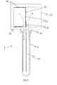
- In
Figure 1 an exemplary embodiment of asolar heat collector 1 for heating a circulating fluid is shown in cross-section, which comprises an evacuatedglass tube 2 with aninner glass tube 3 having anopen end 4 and a closedend 5 and an outer glass tube 6 having anopen end 7 and a closed end 8. Theopen end 4 of theinner glass tube 3 and theopen end 7 of the outer glass tube 6 are joint and sealed, whereas the inner space between bothglass tubes 3 and 6 is evacuated. The inner andouter tubes 3 and 6 have smooth inner and outer surfaces. The outer wall of theinner glass tube 3 has athin coating 9 of carbon black, aluminum, copper, silver or phosphor coating with a thickness of about 1000 Å. Aninsert 10 is positioned exactly on the central axis of theinner glass tube 3, such that afirst channel 11 and asecond channel 12 are defined in theinner glass tube 3, which are identical, i.e. the first and second channels have the same cross-section. The upper end of theinsert 10 is provided at a distance to the closedend 5 of theinner glass tube 3, which leaves open aspace 13 with the same dimension as the cross-sections of the first andsecond channels solar heat collector 1 is mounted on aduct 15 by means of acircular coupling piece 16. Theduct 15 is divided by apartition 17 in asupply channel 18 and areturn channel 19. - The inner and
outer glass tubes 3 and 6 have a wall thickness of 1-2 mm. Theinner glass tube 3 has an inner diameter of 40-45 mm, preferably 43 mm. The outer glass tube 6 has an outer diameter of 60-65 mm, preferably 63 mm. However, the inner diameter can be up to 150 mm and the outer diameter up to 170 mm. The total length of the outer tube 6 is between 150 cm and 180 cm. - The
insert 10 can be a thin plate of glass or made of sheet metal. Other materials as synthetic material, ceramics or carbon fibres can be used for producing theinsert 10. Theinsert 10 has a thickness of about 0.5 to 1.0 mm. -
Figure 2 shows a rectangular duct ormanifold 20 made of sheet metal with severalcircular openings 21 on which a row ofsolar heat collectors 1 can be connected. Other materials as synthetic material, ceramics or carbon fibres can also be used for producing theduct 20. In the duct 20 apartition 22 of sheet metal withupstanding edges duct 20 by formingsupply channel 18 and returnchannel 19.Figure 3 shows aninsolation tube 25 withopenings 26 which correspond to theopenings 21 ofduct 20. Theinsolation tube 25 is a sleeve made of glass wool, rockwool or ceramic insulation. InFigure 4 arectangular cover 27 is shown withopenings 28 corresponding to theopenings 21. Asmall overlap 29 is provided to thecover 27 for closing. In use theduct 20 is surrounded by theinsolation tube 25 which is enclosed bycover 27. - In
Fig. 5 duct 20 withpartition 22 is shown in more detail. Theupstanding edge 23 comprises distancingparts 30 bent at right angles to thecentral sheet plate 31 of thepartition 22 whereas there aregaps 32 between the distancingparts 30 commensurate to the width of thecircular openings 21 of theduct 20. At the opposite side of the distancingparts 30 theedge 24 bent at right angles to thecentral sheet plate 30 is continuous. -
Fig. 6 shows a cross-section through thesolar heat collector 1 mounted on theduct 20, whereas thepartition 22 with theupstanding edge 24 and a distancingpart 30 can be seen. On thecentral sheet plate 31 of thepartition 22 anelongate clip member 33 is mounted, in whichclip member 33 theinsert 10 of thesolar heat collector 1 is jammed in between. -
Fig. 7 shows twosolar heat collectors duct 20 to show the air flow by arrows "Air in" and "Air out" through the evacuatedglass tubes 2 and into theduct 20. - In
Figures 8 to 19 different variants of theinsert 10 are depicted. -
Figure 8 shows a cross-section through the evacuatedglass tube 2 and afirst embodiment 10A of theinsert 10 with a flatcentral part 35 and two identicalcurved wings glass tube 2. Thewings glass tube 2.Figure 9 shows theinsert 10A in perspective view. As can be seen inFig. 9 the lengths of thewings central part 35 so that afree end 40 is left. - Returning now to
Fig. 7 the free ends 40 of theinserts 10 ofheat collectors clip member 33 to thepartition 22 ofduct 20. Thus, thewings insert 10A (seeFig. 8 ) are flush with theduct 20 to create an even and smooth fluid flow between theduct 20 and the evacuatedglass tube 2. -
Figure 10 shows a cross-section andFig. 11 a perspective view of asecond embodiment 10B of theinsert 10 with a serratedcentral part 38 and the two identicalcurved wings central part 38 have a triangular shape and a width of 5-10 mm. -
Figure 12 shows a cross-section andFigure 13 a perspective view of athird embodiment 10C of theinsert 10 with a corrugatedcentral part 39 and the two identicalcurved wings - The serrated
central part 38 ofinsert 10B (seeFig. 10 ) and the corrugatedcentral part 39 ofinsert 10C exert more tension to thecurved wings tube 2 so that thewings second channels insert - In
Figure 14 a cross-section and inFigure 15 a perspective view of afourth embodiment 10D of theinsert 10 is shown having a cross shapedinner part 45 which divide the inner space of the evacuatedglass tube 2 in twofirst channels second channels - In
Figure 16 a cross-section and inFigure 17 a perspective view of afifth embodiment 10E of theinsert 10 is shown, in which theinsert 10E is a generally cross-shaped without wings. Theinsert 10E consists of an elongated first flatsheet metal part 46 and two identical second flatsheet metal parts 47 which have half the width of thefirst part 46 and a length which is little shorter as the length of thefirst part 46 leaving thefree end 40 for connecting theinsert 10E with the clip member 33 (seeFig. 6 ). The twosecond parts 47 are mounted in right angles along the centre lines on both sides of thefirst part 46. In theembodiment 10E the width of the first flatsheet metal part 46 is exactly commensurate to the inner diameter of the evacuatedglass tube 2, so that thecross-shaped insert 10E is fixed in theglass tube 2 when it is inserted. In this manner there are likewise twofirst channels second channels - In
Figure 18 a cross-section and inFigure 19 a perspective view of asixth embodiment 10F of theinsert 10 is shown, in which the insert has a flatcentral part 50 and bulging edges 51 with rounded rims so that theinsert 10F is pinched towards theinner glass tube 3. Also here there is anopen space 13 with the same dimension as the cross-sections of the first andsecond channels Figure 19 the evacuatedglass tube 2 is partly cut away to show theinsert 10F and theopen space 13 at theclosed end 5. - Instead of pinching the
insert 10F within theinner glass tube 3, theinsert 10F can be manufactured in one piece with the production of theinner glass tube 3. - The solar heat collector as described above is manufactured as follows: the
inner glass tube 3 having anopen end 4 and aclosed end 5 and the outer glass tube 6 having anopen end 7 and a closed end 8 are produced and both glass tubes are connected at the open ends 4 and 7, such that a space is left between theinner tube 3 and the outer tube 6. Said space is then evacuated by means of an evacuation pump. Further theinsert 10 is provided into theinner tube 1 which divide theinner tube 1 in afirst channel 11 and asecond channel 12 such that the first and second channels and aspace 13 between the end of theinsert 10 and theclosed end 5 of theinner tube 3 define the same cross-section.
Claims (14)
- Solar heat collector (1) for heating a circulating fluid with an inner glass tube (3) having an open end (4) and a closed end (5) and an outer glass tube (6) having an open end (7) and a closed end (8), which glass tubes are connected at the open ends (4, 7) of both glass tubes, and the space between the inner tube (3) and the outer tube (6) being evacuated, whereas the inner space of the inner tube (3) being divided by an insert (10) to define a first channel (11) and a second channel (12) within the inner tube (3), said channels being connected at the closed end (5) of the inner tube, characterized in that the inner glass tube (3) and the outer glass tube (6) have smooth inner and outer surfaces and that the insert (10) is provided such that the first and second channels (11, 12) and a space (13) between the end of the insert (10) and the closed end (5) of the inner tube (3) defining the same cross-section.
- Solar heat collector according to claim 1, characterized in that the insert (10) is a thin plate of glass dividing the inner space of the inner glass tube, such that the first and second channels (11, 12) are identical.
- Solar heat collector according to claim 1 or claim 2, characterized that the insert (10) is extruded in one-piece with the inner glass tube.
- Solar heat collector according to claim 1, characterized in that the insert (10) is a sheet metal dividing the inner space of the inner glass tube, such that the first and second channels (11, 12) are identical.
- Solar heat collector according to one of claims 2 to 4, characterized that the insert (10A) has on both length sides curved wings (36, 37) having the same curvature as the curvature of the inner tube.
- Solar heat collector according to claim 5, characterized in that the wings (36, 37) are press-fit arranged towards the inner surface of the inner glass tube.
- Solar heat collector according to one of claims 2 to 6, characterized in that at least one surface of the insert (10B, 10C) having longitudinal ribs.
- Solar heat collector according to claim 7, characterized in that the ribs (38) have a triangular shape.
- Solar heat collector according to claim 7, characterized in that the ribs (39) have a corrugated shape.
- Solar heat collector according to one of claims 1 to 5, characterized in that the insert (10D, 10E) has a cross shaped inner part (45), which divides the inner space of the evacuated glass tube (2) in two first channels (11 A, 11 B) and in two second channels (12A, 12B).
- Solar heat collector according to claim 10, characterized in that the cross shaped inner part (45) comprising an elongated first flat sheet metal part (46) and two identical second flat sheet metal parts (47) which are mounted at right angles along the centre lines on both sides of the first sheet metal part (46), whereas the width of first part (46) and of the two second parts (47) are commensurate to the inner diameter of the evacuated glass tube (2).
- Solar heat collector according to one of claims 1 to 4, characterized in that the insert (10F) has a flat central part (50) and bulging edges (51) with rounded rims so that the insert (10F) is pinched towards the inner glass tube (3) of the evacuated glass tube (2).
- Process for manufacturing a solar heat collector according to one of claims 1 to 11, wherein an inner glass tube (3) having an open end (4) and a closed end (5) and an outer glass tube (6) having an open end (7) and a closed end (8) are produced and connected at the open ends (4, 7) of both glass tubes, such that a space is left between the inner tube (3) and the outer tube (6), wherein further said space is evacuated by means of an evacuation pump, further providing an insert into the inner tube (1) which divide the inner tube (1) in a first channel (11) and a second channel (12) such that the first and second channels (11, 12) and a space (13) between the end of the insert (10) and the closed end (5) of the inner tube (3) define the same cross-section.
- Process according to claim 13, characterized in that the insert (10) made of glass is extruded in one piece with the production of the inner tube (3).
Applications Claiming Priority (2)
| Application Number | Priority Date | Filing Date | Title |
|---|---|---|---|
| CH12792013 | 2013-07-17 | ||
| CH16542013 | 2013-09-27 |
Publications (1)
| Publication Number | Publication Date |
|---|---|
| EP2827078A1 true EP2827078A1 (en) | 2015-01-21 |
Family
ID=51211558
Family Applications (1)
| Application Number | Title | Priority Date | Filing Date |
|---|---|---|---|
| EP14176938.0A Withdrawn EP2827078A1 (en) | 2013-07-17 | 2014-07-14 | Solar heat collector for heating a circulating fluid and process for manufacturing a solar heat collector |
Country Status (4)
| Country | Link |
|---|---|
| US (1) | US20150020794A1 (en) |
| EP (1) | EP2827078A1 (en) |
| AU (1) | AU2014204438A1 (en) |
| CA (1) | CA2857033A1 (en) |
Families Citing this family (1)
| Publication number | Priority date | Publication date | Assignee | Title |
|---|---|---|---|---|
| US11499754B2 (en) * | 2017-12-21 | 2022-11-15 | Cordivari S.R.L. | Dissipator integrated into a compact solar collector |
Citations (14)
| Publication number | Priority date | Publication date | Assignee | Title |
|---|---|---|---|---|
| US4016860A (en) * | 1976-01-12 | 1977-04-12 | Owens-Illinois, Inc. | Tubular solar energy collection system utilizing air media |
| WO1981000615A1 (en) | 1979-08-29 | 1981-03-05 | J Hanlet | Electromagnetic energy absorber |
| WO1983003891A1 (en) * | 1982-05-04 | 1983-11-10 | Geoffrey Lester Harding | Solar energy collector system |
| US4512333A (en) * | 1983-05-23 | 1985-04-23 | Kimex International Technologies, Inc. | Solar collector panel and method |
| US4554908A (en) * | 1979-08-29 | 1985-11-26 | Alpha-Omega Development Inc. | Electromagnetic energy absorber |
| DE29819819U1 (en) * | 1997-11-14 | 1999-01-21 | Thermomax Ltd | Vacuum solar collector with direct flow |
| EP1736715A1 (en) * | 2005-06-23 | 2006-12-27 | Sgl Carbon Ag | Vacuum tube for solar collectors with improved heat transfer |
| CN2888355Y (en) * | 2006-03-29 | 2007-04-11 | 孙薛胜 | Solar vacuum tube |
| EP1840474A2 (en) * | 2006-03-29 | 2007-10-03 | Fafco Incorporated | Kit for solar water heating system |
| DE102007018644A1 (en) * | 2007-04-19 | 2008-10-23 | Fraunhofer-Gesellschaft zur Förderung der angewandten Forschung e.V. | Solar tube, solar tube collector and use |
| US20090139515A1 (en) * | 2007-12-03 | 2009-06-04 | Gee Randy C | Solar thermal energy collector |
| WO2009077965A2 (en) * | 2007-12-14 | 2009-06-25 | Activehome Ltd. | Vacuum tube solar collector |
| CN201488359U (en) * | 2009-04-16 | 2010-05-26 | 盛道林 | Solar vacuum tube and solar water heater |
| WO2011017750A1 (en) | 2009-08-11 | 2011-02-17 | Urs Furter | Solar hot generator |
-
2014
- 2014-07-14 EP EP14176938.0A patent/EP2827078A1/en not_active Withdrawn
- 2014-07-16 AU AU2014204438A patent/AU2014204438A1/en not_active Abandoned
- 2014-07-17 CA CA2857033A patent/CA2857033A1/en not_active Abandoned
- 2014-07-17 US US14/334,018 patent/US20150020794A1/en not_active Abandoned
Patent Citations (14)
| Publication number | Priority date | Publication date | Assignee | Title |
|---|---|---|---|---|
| US4016860A (en) * | 1976-01-12 | 1977-04-12 | Owens-Illinois, Inc. | Tubular solar energy collection system utilizing air media |
| WO1981000615A1 (en) | 1979-08-29 | 1981-03-05 | J Hanlet | Electromagnetic energy absorber |
| US4554908A (en) * | 1979-08-29 | 1985-11-26 | Alpha-Omega Development Inc. | Electromagnetic energy absorber |
| WO1983003891A1 (en) * | 1982-05-04 | 1983-11-10 | Geoffrey Lester Harding | Solar energy collector system |
| US4512333A (en) * | 1983-05-23 | 1985-04-23 | Kimex International Technologies, Inc. | Solar collector panel and method |
| DE29819819U1 (en) * | 1997-11-14 | 1999-01-21 | Thermomax Ltd | Vacuum solar collector with direct flow |
| EP1736715A1 (en) * | 2005-06-23 | 2006-12-27 | Sgl Carbon Ag | Vacuum tube for solar collectors with improved heat transfer |
| CN2888355Y (en) * | 2006-03-29 | 2007-04-11 | 孙薛胜 | Solar vacuum tube |
| EP1840474A2 (en) * | 2006-03-29 | 2007-10-03 | Fafco Incorporated | Kit for solar water heating system |
| DE102007018644A1 (en) * | 2007-04-19 | 2008-10-23 | Fraunhofer-Gesellschaft zur Förderung der angewandten Forschung e.V. | Solar tube, solar tube collector and use |
| US20090139515A1 (en) * | 2007-12-03 | 2009-06-04 | Gee Randy C | Solar thermal energy collector |
| WO2009077965A2 (en) * | 2007-12-14 | 2009-06-25 | Activehome Ltd. | Vacuum tube solar collector |
| CN201488359U (en) * | 2009-04-16 | 2010-05-26 | 盛道林 | Solar vacuum tube and solar water heater |
| WO2011017750A1 (en) | 2009-08-11 | 2011-02-17 | Urs Furter | Solar hot generator |
Non-Patent Citations (2)
| Title |
|---|
| DATABASE WPI Section PQ Week 201029, Derwent World Patents Index; Class Q74, AN 2010-E28059, XP002732373 * |
| DATABASE WPI Section PQ Week 201043, Derwent World Patents Index; Class Q74, AN 2010-G64515, XP002732372 * |
Also Published As
| Publication number | Publication date |
|---|---|
| US20150020794A1 (en) | 2015-01-22 |
| CA2857033A1 (en) | 2015-01-17 |
| AU2014204438A1 (en) | 2015-02-05 |
Similar Documents
| Publication | Publication Date | Title |
|---|---|---|
| US4120285A (en) | Modular tubular solar energy collector apparatus | |
| AU2011257255B2 (en) | Module for a thermal absorber of a solar receiver, absorber comprising at least one such module and receiver comprising at least one such absorber | |
| US4122832A (en) | Solar collector | |
| US10352590B2 (en) | Mini-channel tube solar collector | |
| EP2827078A1 (en) | Solar heat collector for heating a circulating fluid and process for manufacturing a solar heat collector | |
| KR102098007B1 (en) | Solar energy collector assembly kit for photovoltaic panel, solar-heat composite assembly and manufacturing method thereof | |
| ITTO20100223A1 (en) | HEAT EXCHANGER | |
| EP2754977A1 (en) | A solar collector having a corrugated tube | |
| CN107917461A (en) | A kind of radiator | |
| KR101445786B1 (en) | boiler heat exchanger | |
| EP2391853B1 (en) | Heat exchanger module | |
| CN104864610A (en) | Dual-channel air collector | |
| CN110375571B (en) | Inner sleeve heat exchange phase change energy storage corrugated pipe | |
| RU144024U1 (en) | SECTOR TYPE RADIATOR AND RADIATOR SECTION FOR ITS MANUFACTURE | |
| CN204535147U (en) | Non-tracking formula solar thermal collector | |
| CN211120044U (en) | Solar heat collecting pipe device | |
| AU2011101413B4 (en) | Solar Hot Air Generator | |
| CN203190599U (en) | Electromagnetic energy circuitous heat exchanger | |
| RU186579U1 (en) | SOLAR COLLECTOR | |
| RU51179U1 (en) | WATER HEATING RADIATOR | |
| CN106322843A (en) | Micro-channel heat exchanger | |
| WO2007138117A1 (en) | Absorber plate for solar collector, the method for manufacturing it and the solar collector | |
| CN102840689A (en) | Solar heat collector | |
| CN203824125U (en) | High temperature heat collection device | |
| RU59217U1 (en) | WATER HEATING RADIATOR |
Legal Events
| Date | Code | Title | Description |
|---|---|---|---|
| 17P | Request for examination filed |
Effective date: 20140714 |
|
| AK | Designated contracting states |
Kind code of ref document: A1 Designated state(s): AL AT BE BG CH CY CZ DE DK EE ES FI FR GB GR HR HU IE IS IT LI LT LU LV MC MK MT NL NO PL PT RO RS SE SI SK SM TR |
|
| AX | Request for extension of the european patent |
Extension state: BA ME |
|
| PUAI | Public reference made under article 153(3) epc to a published international application that has entered the european phase |
Free format text: ORIGINAL CODE: 0009012 |
|
| RBV | Designated contracting states (corrected) |
Designated state(s): AL AT BE BG CH CY CZ DE DK EE ES FI FR GB GR HR HU IE IS IT LI LT LU LV MC MK MT NL NO PL PT RO RS SE SI SK SM TR |
|
| R17P | Request for examination filed (corrected) |
Effective date: 20150713 |
|
| 17Q | First examination report despatched |
Effective date: 20180111 |
|
| STAA | Information on the status of an ep patent application or granted ep patent |
Free format text: STATUS: THE APPLICATION IS DEEMED TO BE WITHDRAWN |
|
| 18D | Application deemed to be withdrawn |
Effective date: 20180523 |