EP1736680B1 - Frein électro-mécanique - Google Patents
Frein électro-mécanique Download PDFInfo
- Publication number
- EP1736680B1 EP1736680B1 EP06013021A EP06013021A EP1736680B1 EP 1736680 B1 EP1736680 B1 EP 1736680B1 EP 06013021 A EP06013021 A EP 06013021A EP 06013021 A EP06013021 A EP 06013021A EP 1736680 B1 EP1736680 B1 EP 1736680B1
- Authority
- EP
- European Patent Office
- Prior art keywords
- switch
- linearly movable
- movable member
- electro
- frictional
- Prior art date
- Legal status (The legal status is an assumption and is not a legal conclusion. Google has not performed a legal analysis and makes no representation as to the accuracy of the status listed.)
- Expired - Fee Related
Links
- 230000008859 change Effects 0.000 claims description 25
- 238000000926 separation method Methods 0.000 claims description 9
- 230000007423 decrease Effects 0.000 claims description 5
- 238000006073 displacement reaction Methods 0.000 claims description 4
- 238000006243 chemical reaction Methods 0.000 claims description 3
- 230000004044 response Effects 0.000 claims description 2
- 230000003247 decreasing effect Effects 0.000 description 5
- 230000007246 mechanism Effects 0.000 description 5
- 239000000356 contaminant Substances 0.000 description 2
- 238000000034 method Methods 0.000 description 2
- 230000009467 reduction Effects 0.000 description 2
- 230000005540 biological transmission Effects 0.000 description 1
- 239000000919 ceramic Substances 0.000 description 1
- 238000001514 detection method Methods 0.000 description 1
- 238000010586 diagram Methods 0.000 description 1
- 230000000694 effects Effects 0.000 description 1
- 239000011810 insulating material Substances 0.000 description 1
- 239000000463 material Substances 0.000 description 1
- 238000012986 modification Methods 0.000 description 1
- 230000004048 modification Effects 0.000 description 1
- 238000012544 monitoring process Methods 0.000 description 1
- 230000004304 visual acuity Effects 0.000 description 1
Images


Classifications
-
- F—MECHANICAL ENGINEERING; LIGHTING; HEATING; WEAPONS; BLASTING
- F16—ENGINEERING ELEMENTS AND UNITS; GENERAL MEASURES FOR PRODUCING AND MAINTAINING EFFECTIVE FUNCTIONING OF MACHINES OR INSTALLATIONS; THERMAL INSULATION IN GENERAL
- F16D—COUPLINGS FOR TRANSMITTING ROTATION; CLUTCHES; BRAKES
- F16D65/00—Parts or details
- F16D65/14—Actuating mechanisms for brakes; Means for initiating operation at a predetermined position
- F16D65/16—Actuating mechanisms for brakes; Means for initiating operation at a predetermined position arranged in or on the brake
- F16D65/18—Actuating mechanisms for brakes; Means for initiating operation at a predetermined position arranged in or on the brake adapted for drawing members together, e.g. for disc brakes
-
- F—MECHANICAL ENGINEERING; LIGHTING; HEATING; WEAPONS; BLASTING
- F16—ENGINEERING ELEMENTS AND UNITS; GENERAL MEASURES FOR PRODUCING AND MAINTAINING EFFECTIVE FUNCTIONING OF MACHINES OR INSTALLATIONS; THERMAL INSULATION IN GENERAL
- F16D—COUPLINGS FOR TRANSMITTING ROTATION; CLUTCHES; BRAKES
- F16D66/00—Arrangements for monitoring working conditions, e.g. wear, temperature
- F16D2066/003—Position, angle or speed
-
- F—MECHANICAL ENGINEERING; LIGHTING; HEATING; WEAPONS; BLASTING
- F16—ENGINEERING ELEMENTS AND UNITS; GENERAL MEASURES FOR PRODUCING AND MAINTAINING EFFECTIVE FUNCTIONING OF MACHINES OR INSTALLATIONS; THERMAL INSULATION IN GENERAL
- F16D—COUPLINGS FOR TRANSMITTING ROTATION; CLUTCHES; BRAKES
- F16D66/00—Arrangements for monitoring working conditions, e.g. wear, temperature
- F16D2066/005—Force, torque, stress or strain
-
- F—MECHANICAL ENGINEERING; LIGHTING; HEATING; WEAPONS; BLASTING
- F16—ENGINEERING ELEMENTS AND UNITS; GENERAL MEASURES FOR PRODUCING AND MAINTAINING EFFECTIVE FUNCTIONING OF MACHINES OR INSTALLATIONS; THERMAL INSULATION IN GENERAL
- F16D—COUPLINGS FOR TRANSMITTING ROTATION; CLUTCHES; BRAKES
- F16D2121/00—Type of actuator operation force
- F16D2121/18—Electric or magnetic
- F16D2121/24—Electric or magnetic using motors
Definitions
- the present invention relates to an electro-mechanical brake in which a brake pad is driven by a motor to generate a braking force.
- JP-A-2004-92812 discloses an example of an electro-mechanical brake for automobile in which a motor other than a hydraulic means drives a brake pad to generate a braking force.
- a disk brake system of floating type in which a disk rotor is clamped between brake pads of a pair by the motor, a ball-screw mechanism for converting a rotation of the motor to a linear movement and a linearly movable part of the ball-screw mechanism.
- a piston position pad contact position
- a piston is moved with respect to the pad contact position to adjust a clearance (pad clearance) between the brake pad and the disk rotor and control a pad pressing force.
- an accuracy in determining the pad contact position affects an accuracy in adjusting the pad clearance and an accuracy in controlling the pad pressing force.
- a pressing force sensor and an elastic member are arranged on a piston, a value of the pad pressing force at a timing at which brake pads contact the disk rotor is experimentally predetermined by moving the piston to increase the pad pressing force, and a position of the piston at which an actual pad pressing force becomes slightly greater than the above mentioned value during an operation for actually detecting the pad contact position is determined as the pad contact position to improve the accuracy in detecting the pad contact position.
- An object of the present invention is to provide an electro-mechanical brake in which a pad contact position can be correctly detected without a pressing force sensor to enable a braking force to be controlled correctly so that a vehicle can be driven safely.
- an electromechanical brake capable of detecting a piston position is characterized by a switch arranged at a position where a pad pressing force is borne when the pad pressing force is generated so that the switch is changed between On condition and Off condition in accordance with whether or not the pressing force is less than a certain level, and/or an elastic member arranged to urge a movable part of the switch in a return direction opposite to a direction of the pressing force to keep the switch at the On condition when the pressing force is less than the certain level and at the Off condition when the pressing force is not less than the certain level.
- the pad contacting position can be correctly detected by detecting a position of the piston where the switch is changed between On condition and Off condition.
- the pad contact position can be detected accurately during a stoppage or running.
- a pressing force sensor for measuring the pad pressing force is unnecessary, a design with taking a reliability of the pressing force sensor under harsh vibration and temperature on vehicle wheel into consideration is not needed, and the electro-mechanical brake of low cost can be provided. Further, by detecting the pad contacting position accurately, an accuracy in controlling the braking force can be improved so that the electro-mechanical brake can provide safe running and braking.
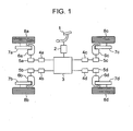
- an electro-mechanical brake of the vehicle has wheels 8a-8d, disk rotors 7a-7d rotatable with the wheels 8a-8d, electro-mechanical brake actuators 6a-6d for pressing the disk rotors 7a-7d, a brake pedal 1, a stroke sensor 2 for converting a moved value of the brake pedal 1 to an electric signal, a main controller 3 for controlling a braking force for each of the wheels in accordance with the electric signal from the stroke sensor 2, electro-mechanical brake controllers 4a-4d for controlling respectively the electromechanical brakes for the wheels on the basis of an electric signal output from the main controller 3, and motor drivers 5a-5d for supplying electric currents to motors of the electro-mechanical brake actuators 6a-6d. so that the motors are driven in accordance with the electric signals output from the electro-mechanical brake controllers 4a-4d.
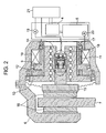
- the electro-mechanical brake actuator 6 has a motor coil 10 energized by an electric current from the motor driver 5, a motor current sensor 20 for measuring the electric current flowing through the motor coil 10, a motor rotor 9 rotating in accordance with a change of magnetic field of the motor coil, a magnet 11 fixed to the motor rotor 9, a reduction gear 12 for reducing a rotational velocity of the motor rotor 9 to amplify a torque, a ball-screw 13 as a rotational movement-linear movement converting mechanism for converting the reduced rotational movement of the reduction gear 12 to a linear movement, a piston moved linearly by a ball-screw rod 14, brake pads 16a, 16b to be pressed against the disk rotor 7 by the piston, an angular resolver 17 for measuring a rotational movement of the motor rotor 9, a pad contact position detector 18 for detecting the pad contacting position, an ampere meter 19 for measuring
- a method for controlling the pad pressing force in the above mentioned electro-mechanical brake will be explained in detail.
- a needed braking force is calculated by the main controller 3 from a pressed value of the pedal by a driver and a movement of the vehicle, a pad pressing force order is determined to be output to the electro-mechanical brake controller 4.
- the electro-mechanical brake controller 4 calculates a motor position needed to generate a pad pressing force corresponding to the pad pressing force order and the motor electric current needed to achieve the motor position.
- the motor driver 5 outputs to the motor coil 10 an electric current order enabling the motor electric current calculated by the electro-mechanical brake controller 4 to actually flow through the motor coil 10. When the electric current flows through the motor coil 10 to rotate the motor rotor 9, the piston is driven by the rotation.
- a rotating value (motor position) of the motor rotor 9 is measured by the angular resolver 17 to feed back the measured motor position to the electro-mechanical brake controller 4 so that the motor position is controlled. Since the pad pressing force is determined univocally by the motor position and a rigidity of the electro-mechanical brake actuator, the pad pressing force can be estimated by the motor position and the rigidity of the electro-mechanical brake actuator predetermined experimentally. Therefore, by controlling the motor position, the pad pressing force can be controlled. If the pad contacting position at which the pad pressing force becomes more than zero when moving the piston toward the pad to increase the pad pressing force is detected correctly, the pad pressing force can be controlled correctly. Incidentally, the pad contacting position is a position at which the pad pressing force becomes zero when moving the piston away from the pad to decrease the pad pressing force. In the electromechanical brake, the pad pressing force is controlled by controlling the motor position.
- Fig. 3 shows in detail the pad contact position detector 18.
- the pad contact position detector 18 has a plunger 22 movable linearly in a hollow area of the rod 14 of the ball-screw, an insulating member 23 received by a hollow area of the plunger 22, a conductive member 22 fixed to the insulating member 23, an insulating plate 26, a pair of electrodes 27a and 27b fixed by conductive screws 28a and 28b, lead wires 29a and 29b connected to the electrodes 27a and 27b, and a spring 25 arranged between the insulating member 23 and insulating plate 26 to be urged away from each other.
- the insulating member 23 and the insulating plate 26 are made of ceramic, and the spring 25 is coated with an insulating material, so that the electric current is prevented from flowing in the conductive members if the plunger 22 and the ball-screw rod 14 are conductive. Further, when the pad pressing force is increased after the conductive member 24 contacts the electrodes 27a and 27b, the conductive member 24 and the electrodes 27a and 27b also bear the pressing force.
- the plunger 22 is linearly movable in the hollow area of the ball-screw rod 14 in a horizontal direction in fig. 2 . Therefore, a dimension of the plunger 22 in a direction perpendicular to the linear moving direction is slightly smaller than a dimension of the hollow area of the ball-screw rod 14.
- a greased 0 ring 30 is mounted on the plunger 22. The ring 30 prevents the proceeding of contaminant, and damps the vibration of the plunger 22 so that the electric current signal measured by the ampere meter 19 is stabilized.
- the pad contact position detector 18 is arranged at a right side with respect to the disk rotor 7 in fig. 2 . If the pad contact position detector 18 is arranged at a left side with respect to the disk rotor 7 in fig. 2 , the whole of the electro-mechanical brake actuator 6 needs to be moved by the spring 25 so that the conductive member 24 is separated from the electrodes 27a and 27b when the pad pressing force decreases to zero, whereby a spring constant of the spring 25 needs to be great.
- the pad contact position detector 18 is arranged at the right side with respect to the disk rotor 7a-7d, only the linearly movable members between the plunger 22 and the disk rotor 7 needs to be moved so that conductive member 24 is separated from the electrodes 27a and 27b, whereby the spring constant may be small.
- the pad contact position detector 18 is arranged on the linearly movable brake pads 16a, 16b, piston 15, ball-screw rod 14 or the like to enable the pad pressing force to be applied directly to the plunger 22, the detection of pad contacting position can be more accurately in comparison with a case in which the pad contact position detector 18 is arranged on a non-linearly-movable member.
- the pad contact position detector 18 is arranged at an outside of the casing and the pressing force is transmitted through a distortion of the casing so that the pad contact position detector 18 is arranged on the nonlinearly-movable member, since the pad pressing force is transmitted to the plunger 22 indirectly, the accuracy in detecting the pad contacting position is deteriorated.
- an effect of that the lead wires 29a, 29b of the pad contact position detector 18 are stationary is brought about so that a reliability of the lead wires 29a, 29b is improved.
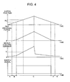
- Fig. 4 includes diagrams showing schematically the piston position, the pad pressing force, the motor current and the switch signal on abscissa representing time elapse, obtained when the piston is moved forward to increase the pad pressing force at constant velocity during a predetermined time period and subsequently moved backward to decrease the pad pressing force. Incidentally, at time elapse of zero, a pad clearance is maintained. Under this situation, time periods A, B, C, D and E in lower parts in fig.
- FIG. 5 is view showing schematically a relationship between the piston position and the pad pressing force.
- A, B, C, D, E in fig. 5 correspond to A, B, C, D, E in fig. 4 .
- a range (A, E) corresponds to the piston position in which the pad clearance exists
- a range (B, D) corresponds to the piston position in which the pad pressing force is borne by only the elasticity of the spring 25
- a range (C) corresponds to the piston position in which the pad pressing force is borne partially by the contact between the conductive member 24 and the electrodes 24a, 27b.
- a piston displacement value s corresponding to the range (B, D) is a distance from a start of contact between the brake pads 16a, 16b and the disk rotor 7a-7d to a start of generating the switch current when the piston is moved to increase the pad pressing force.
- the pad contacting position is a piston position behind by s from the piston position at the change of the switch current. Further, when decreasing the pad pressing force, the pad contacting position may be a piston position ahead by s from the piston position at which the switch current becomes zero.
- the value s is obtainable from a design or initial distance (which is limited by a mechanical stopper to be prevented from exceeding a predetermined value) between the conductive member 24 and the electrodes 24a, 27b, or obtainable experimentally (that is, for example, from a piston displacement between the change to zero or from zero of the switch current and a significant increase or decrease of the motor current for generating a reaction force against the force of the spring 25 in response to the contact or separate between the brake pad 16 and the disk rotor 7).
- the pad contacting position can be easily obtainable by the pad contact position detector when increasing or decreasing the pad pressing force, and if the pad contacting position is an average position between the pad contacting position obtained when increasing the pad pressing force and the pad contacting position obtained when decreasing the pad pressing force, the pad contacting position can be measured more accurately. Further, when the braking is prevented, the piston is positioned away by not less than s from the piston position at which the switch current changes, so that the pad pressing force is prevented from being applied to the brake pad when the braking should be prevented.
- the motor current increases in proportion to the piston position as shown in fig. 4 . Therefore, the brake is operated during the stoppage or running of the vehicle to inspect the pad contact position detector 18 and the motor current sensor 20.
- the piston is moved to increase the pad pressing force with monitoring the switch current and motor current, and the switch current is kept zero although the motor current reaches a predetermined current value It, it is decided that the pad contact position detector 18 is in failure. Further, when the motor current is kept at not more than It although the piston is moved by Pt after the switch current becomes more than zero, it is decided that the motor current sensor is in failure.
- the electric circuit is cut off to prevent the electric current from flowing therethrough when the pad pressing force is not generated, and the electric circuit is formed to allow the electric current to flow therethrough when the pad pressing force is generated.
- the electric current is detected by the electro-mechanical brake controller 4 when the pad pressing force is not generated, and the electric current is not detected by the electromechanical brake controller 4 when the pad pressing force is generated.
- FIG. 6 is a schematic view of an electric circuit by which an electric signal is input into the electro-mechanical brake controller 4 when the electric circuit (circuit A) is not formed by the pad contact position detector 18 so that a relay enables the electric current to be detected by the ampere meter 19, and the electric signal is prevented from being input into the electro-mechanical brake controller 4 when the electric circuit (circuit A) is formed by the pad contact position detector 18 so that the relay prevents the electric current from being detected by the ampere meter 19.
- a switch in the relay 31 is closed to form a circuit B to enable the electric signal to be input to the electro-mechanical brake controller 4a-4d, when the circuit is cut off.
- the switch in the relay 31 is opened to cut off the circuit B to prevent the electric signal from being input to the electro-mechanical brake controller 4, when the circuit is formed to allow the electric current to flow therethrough.
- the pad contact position detector 18 is effectively applicable to the electro-mechanical brake including a plurality of the actuators as shown in JP-hei-7-144636-A .
- This publication discloses a braking device in which the brake pad is driven by the motor during an initial stage of brake operation of low load and great stroke, and the pad pressing force is adjusted desirably by a piezo-electric element during a brake operation of high load and small stroke. If the pad contact position detector 18 is applied to this system, a change between the motor drive and the piezoelectric element drive can be performed effectively with making reference to the piston position at which the switch current changes, so that a brake controllability is improved.
- Fig. 7 shows a second embodiment of the invention. Since a major part of the electro-mechanical brake of this embodiment is similar to the first embodiment, only a distinctive part is explained.
- the pad contact position detector of this embodiment is characterized by a switch 33 whose stroke is greater than the initial clearance between the conductive member 24 and the electrodes 27a, 27b in the first embodiment, and the pad pressing force borne between a right end of a plunger 32 and a switch mounting plate 35.
- the switch 33 when the switch 33 is compressed by the plunger 32 to form the electric circuit, the electric current flows between the lead wires 37a and 37b.
- this pad contact position detector although a movable range of the piston urged by a spring 34 to bear the pad pressing force is greater than that in the first embodiment so that the accuracy in detecting the pad contacting position is deteriorated, there are advantages of that the plunger 32 and the switch contact each other at single point so that the electric signal detected by the ampere meter 19 is stabilized against an inclination of axis, an electric contact point is received by the switch 33 to be easily protected, and the switch structure and the load bearing structure are separated from each other so that the switch 33, the plunger 32 and the switch mounting plate 35 can be formed of respective suitable materials.
- the switch may be a positional sensor measuring a position of the linearly movable member with respect to the frictional member. If a part of the switch (as a positional sensor measuring a position of the linearly movable member with respect to the frictional member) is mounted on the linearly movable member, another part of the switch is mounted on the frictional member, the switch detects the change from the contact to the separation when the switch detects a change from an electrical connection between the part of the switch and the another part of the switch to an electrical disconnection between the part of the switch and the another part of the switch, and the switch detects the change from the separation to the contact when the switch detects a change from the electrical disconnection to the electrical connection, it is preferable for correctly detecting the change between the contact and the separation or secure and sufficient compressing force transmission between the frictional member and the linearly movable member that a major part of the compressing force greater than the part of the compressing force transmitted through the elastic member is transmitted through the part of the switch and the another part of the switch contacting each
Landscapes
- Engineering & Computer Science (AREA)
- General Engineering & Computer Science (AREA)
- Mechanical Engineering (AREA)
- Braking Arrangements (AREA)
Claims (20)
- Frein électromécanique pour une roue (8), comportant un moteur (9, 10), un élément mobile de manière linéaire (14) pouvant être entraîné par le moteur, un élément rotatif (7) connecté à la roue pour tourner avec la roue, un élément de frottement (16) connecté à l'élément mobile de manière linéaire (14) pour se déplacer avec l'élément mobile de manière linéaire et agencé pour être appuyé contre l'élément rotatif (7) afin de générer une force de freinage, et un détecteur (17) pour détecter un déplacement de l'élément de frottement (16), caractérisé en ce que le frein électromécanique comporte en outre un commutateur (24, 27, 33, 20) agencé à une position où une force pour appuyer l'élément de frottement contre l'élément rotatif doit être supportée de sorte qu'un changement de signal électrique est généré lorsque la force est générée pour déplacer un élément mobile du commutateur dans une première direction, et un élément élastique (25, 34) agencé à une position pour générer une force de réaction de sorte que l'élément mobile est poussé par la force de réaction dans une autre direction opposée à la première direction.
- Frein électromécanique selon la revendication 1, dans lequel une constante de rappel de l'élément élastique (25, 34) est inférieure à une constante de rappel de l'élément de frottement (16).
- Frein électromécanique selon 1a revendication 1 ou 2, dans lequel le frein est du type flottant, et le commutateur (24, 27, 33) et l'élément élastique (25, 34) sont agencés au niveau de l'un des côtés de l'élément rotatif (7) avec le moteur (9, 10) et l'élément mobile de manière linéaire (14).
- Frein électromécanique selon l'une quelconque des revendications 1 à 3, dans lequel le commutateur (24, 27, 33) et l'élément élastique (25, 34) sont mobiles de manière linéaire avec l'élément mobile de manière linéaire.
- Frein électromécanique selon l'une quelconque des revendications 1 à 4, dans lequel l'élément élastique (25, 34) est agencé dans une zone stationnaire lorsque l'élément mobile de manière linéaire (14) est entraîné par le moteur (9, 10).
- Frein électromécanique selon l'une quelconque des revendications 1 à 5, dans lequel une dimension maximum de l'élément mobile dans la direction n'est pas inférieure à une dimension maximum de l'élément mobile dans l'autre direction perpendiculaire à la direction.
- Frein électromécanique selon l'une quelconque des revendications 1 à 6, dans lequel le frein électromécanique comporte en outre un détecteur de courant électrique (20) pour détecter un courant électrique appliqué au moteur (19) de sorte qu'un contact entre l'élément de frottement (16) et l'élément rotatif (7) est détecté à partir d'un changement du courant électrique, et un dispositif de détection de défaillance (4) pour détecter une défaillance d'au moins l'un du commutateur (24, 27, 33) de l'élément élastique (25, 34) et du détecteur de courant électrique (20) par l'intermédiaire d'une comparaison entre le contact détecté de manière illative à partir du changement de signal électrique de commutateur (24, 27, 33) et le contact détecté de manière illative à partir du changement du courant électrique.
- Frein électromécanique selon l'une quelconque des revendications 1 à 7, dans lequel une position de l'élément de frottement (16) lorsque le changement de signal électrique est détecté est comprise entre l'élément rotatif (7) et une position de l'élément de frottement (16) lorsque l'on empêche l'élément mobile de manière linéaire (14) d'être entraîné par le moteur (9, 10).
- Frein électromécanique pour une roue (8), comportant un moteur (9, 10), un élément mobile de manière linéaire (14) pouvant être entraîné par le moteur (9, 10) pour se déplacer de manière linéaire, un élément rotatif (7) connecté à la roue (8) pour tourner avec la roue (8), un élément de frottement (16, 15, 22, 23, 32) pouvant être connecté à l'élément mobile de manière linéaire (14) à déplacer de manière linéaire par l'intermédiaire de l'élément mobile de manière linéaire (14) de sorte que l'élément de frottement (16, 15, 22, 23, 32) est appuyé contre l'élément rotatif (7) afin de générer une force de freinage pour la roue (8), et un détecteur (17) pour mesurer une position de l'élément mobile de manière linéaire (14),
caractérisé en ce que le frein électromécanique comporte en outre un élément élastique (25, 34) qui est agencé entre l'élément mobile de manière linéaire (14) et l'élément de frottement (16, 15, 22, 23, 32) à pousser de manière élastique loin l'un de l'autre de sorte qu'au moins une partie d'une force de compression pour appuyer l'élément de frottement (16, 15, 22, 23, 32) contre l'élément rotatif (7) est supportée entre l'élément mobile de manière linéaire (14) et l'élément de frottement (16, 15, 22, 23, 32) via l'élément élastique (25, 34) et élastiquement déformable pour permettre à l'élément mobile de manière linéaire (14) et à l'élément de frottement (16, 15, 22, 23, 32) d'être en contact l'un avec l'autre de sorte que la force de compression peut être supportée entre l'élément mobile de manière linéaire (14) et l'élément de frottement (16, 15, 22, 23, 32) via l'élément élastique (25, 34) et le contact entre l'élément mobile de manière linéaire (14) et l'élément de frottement (16, 15, 22, 23, 32), et un commutateur (24, 27, 33) pouvant délivrer en sortie un signal lorsque le commutateur (24, 27, 33) détecte au moins qu'une distance entre l'élément mobile de manière linéaire (14) et l'élément de frottement (16, 15, 22, 23, 32) devient égale à une distance prédéterminée ou que la distance entre l'élément mobile de manière linéaire (14) et l'élément de frottement (16, 15, 22, 23, 32) devient différente de la distance prédéterminée. - Frein électromécanique selon la revendication 9, dans lequel le commutateur (24, 27, 33) et l'élément élastique (25, 34) sont agencés en parallèle l'un avec l'autre entre l'élément mobile de manière linéaire (14) et l'élément de frottement (16, 15, 22, 23, 32) de sorte que l'on empêche la au moins une partie de la force de compression à supporter par l'élément élastique (25, 34) d'être supportée par le commutateur (24, 27, 33).
- Frein électromécanique selon la revendication 9 ou 10, dans lequel le commutateur (24, 27, 33) est capable de supporter une autre partie de la force de compression de sorte que l'autre partie de la force de compression est transmise entre l'élément mobile de manière linéaire (14) et l'élément de frottement (16, 15, 22, 23, 32) via le commutateur (24, 27, 33), et la au moins une partie de la force de compression à supporter par l'élément élastique (25, 34) est supérieure à l'autre partie de la force de compression à supporter par le commutateur (24, 27, 33) lorsque le commutateur (24, 27, 33) détecte qu'au moins la distance entre l'élément mobile de manière linéaire (14) et l'élément de frottement (16, 15, 22, 23, 32) devient égale à la distance prédéterminée ou que la distance entre l'élément mobile de manière linéaire (14) et l'élément de frottement (16, 15, 22, 23, 32) devient différente de la distance prédéterminée.
- Frein électromécanique selon l'une quelconque des revendications 9 à 11, dans lequel le commutateur (24, 27) détecte que la distance entre l'élément mobile de manière linéaire (14) et l'élément de frottement (16, 15, 22) devient égale à la distance prédéterminée lorsque le commutateur (24, 27) détecte un changement à partir d'une séparation entre l'élément mobile de manière linéaire (14) et l'élément de frottement (16, 15, 22) jusqu'au contact entre l'élément mobile de manière linéaire (14) et l'élément de frottement (16, 15, 22), et le commutateur (24, 27) détecte que la distance entre l'élément mobile de manière linéaire (14) et l'élément de frottement (16, 15, 22) devient différente de la distance prédéterminée lorsque le commutateur (24, 27) détecte un changement à partir du contact jusqu'à la séparation.
- Frein électromécanique selon l'une quelconque des revendications 9 à 12, dans lequel une partie (27) du commutateur est montée sur l'élément mobile de manière linéaire (14), une autre partie (24) du commutateur est montée sur l'élément de frottement (16, 15, 22), le commutateur (24, 27) détecte le changement à partir du contact jusqu'à la séparation lorsque le commutateur (24, 27) détecte un changement d'une connexion électrique entre la partie (27) du commutateur et l'autre partie (24) du commutateur jusqu'à une déconnexion électrique entre la partie (27) du commutateur et l'autre partie (24) du commutateur, et le commutateur (24, 27) détecte le changement à partir de la séparation jusqu'au contact lorsque le commutateur (24, 27) détecte un changement à partir de la déconnexion électrique jusqu'à la connexion électrique.
- Frein électromécanique selon la revendication 12 ou 13, dans lequel le commutateur (24, 27, 33) est capable de supporter une autre partie de la force de compression à transmettre à travers le contact entre l'élément mobile de manière linéaire (14) et l'élément de frottement (16, 15, 22, 32) de sorte que l'autre partie de la force de compression est transmise entre l'élément mobile de manière linéaire (14) et l'élément de frottement (16, 15, 22, 32) via le commutateur (24, 27, 33), et la au moins une partie de la force de compression à supporter par l'élément élastique (25, 34) est supérieure à l'autre partie de la force de compression à supporter par le commutateur (24, 27, 33) lorsque le commutateur détecte le changement entre le contact et la séparation entre l'élément mobile de manière linéaire (14) et l'élément de frottement (16, 15, 22, 32).
- Frein électromécanique selon l'une quelconque des revendications 9 à 14, dans lequel le détecteur (17) détecte la position de l'élément mobile de manière linéaire (14) en réponse à la sortie du signal, et le moteur (9, 10) est commandé pour entraîner l'élément mobile de manière linéaire (14) sur la base de la position détectée de sorte que l'élément mobile de manière linéaire (14) est éloigné de la position détectée d'une distance suffisante pour empêcher la transmission de la force de compression entre l'élément de frottement (16, 15, 22, 32) et l'élément rotatif (7) lorsque l'on empêche la génération de la force de freinage.
- Frein électromécanique selon l'une quelconque des revendications 9 à 15, dans lequel une valeur du signal peut être changée de manière non linéaire lorsque le commutateur (24, 27, 33) détecte au moins que la distance entre l'élément mobile de manière linéaire (14) et l'élément de frottement (16, 15, 22, 32) devient égale à la distance prédéterminée ou que la distance entre l'élément mobile de manière linéaire (14) et l'élément de frottement (16, 15, 22, 32) devient différente de la distance prédéterminée.
- Frein électromécanique selon l'une quelconque des revendications 9 à 16, dans lequel l'élément de frottement (16, 15, 22, 32) inclut des première et seconde parties pouvant être séparées l'une de l'autre, la première partie (16, 15) est agencée pour être positionnée en face de l'élément rotatif de sorte que la première partie (16, 15) peut être appuyée contre l'élément rotatif (7), et la seconde partie (22, 32) peut être connectée à l'élément mobile de manière linéaire (14) de sorte que la force de compression est transmise entre la première partie (16, 15) et l'élément mobile de manière linéaire (14) à travers la seconde partie (22, 32).
- Frein électromécanique selon l'une quelconque des revendications 9 à 17, dans lequel le moteur a un rotor (9) et un stator (10), l'élément mobile de manière linéaire (14) pouvant être entraîné par le moteur (9) afin de se déplacer de manière linéaire par rapport au stator (10), et le détecteur (17) est capable de mesurer la position de l'élément mobile de manière linéaire (14) à partir d'une relation de position en rotation entre le rotor (9) et le stator (10).
- Frein électromécanique selon l'une quelconque des revendications 9 à 18, dans lequel le commutateur (20) est capable de mesurer une valeur de courant électrique délivrée au moteur (9, 10), et le commutateur (20) détecte au moins que la distance entre l'élément mobile de manière linéaire (14) et l'élément de frottement (16, 15, 22, 32) devient égale à une distance prédéterminée ou que la distance entre l'élément mobile de manière linéaire (14) et l'élément de frottement (16, 15, 22, 32) devient différente de la distance prédéterminée lorsque le commutateur (20) détecte un changement brutal de la valeur du courant électrique et détecte que la valeur du courant électrique n'est pas inférieure à une valeur prédéterminée.
- Frein électromécanique selon l'une quelconque des revendications 9 à 19, dans lequel le commutateur (24, 27, 33) détecte que la distance entre l'élément mobile de manière linéaire (14) et l'élément de frottement (16, 15, 22, 32) devient égale à une distance prédéterminée lorsque le commutateur (24, 27, 33) détecte qu'un jeu entre l'élément mobile de manière linéaire (14) et l'élément de frottement (16, 15, 22, 32) diminue jusqu'à une valeur prédéterminée, et le commutateur (24, 27, 33) détecte que la distance entre l'élément mobile de manière linéaire (14) et l'élément de frottement (16, 15, 22, 32) devient différente de la distance prédéterminée lorsque le commutateur (24, 27, 33) détecte que le jeu augmente par rapport à la valeur prédéterminée.
Applications Claiming Priority (1)
| Application Number | Priority Date | Filing Date | Title |
|---|---|---|---|
| JP2005182766A JP2007002904A (ja) | 2005-06-23 | 2005-06-23 | 電動ブレーキ装置 |
Publications (3)
| Publication Number | Publication Date |
|---|---|
| EP1736680A2 EP1736680A2 (fr) | 2006-12-27 |
| EP1736680A3 EP1736680A3 (fr) | 2008-09-24 |
| EP1736680B1 true EP1736680B1 (fr) | 2010-03-03 |
Family
ID=36975237
Family Applications (1)
| Application Number | Title | Priority Date | Filing Date |
|---|---|---|---|
| EP06013021A Expired - Fee Related EP1736680B1 (fr) | 2005-06-23 | 2006-06-23 | Frein électro-mécanique |
Country Status (4)
| Country | Link |
|---|---|
| US (1) | US7849976B2 (fr) |
| EP (1) | EP1736680B1 (fr) |
| JP (1) | JP2007002904A (fr) |
| DE (1) | DE602006012580D1 (fr) |
Families Citing this family (16)
| Publication number | Priority date | Publication date | Assignee | Title |
|---|---|---|---|---|
| JP5001683B2 (ja) * | 2007-03-13 | 2012-08-15 | カヤバ工業株式会社 | 電動ブレーキ |
| KR100884821B1 (ko) * | 2007-07-19 | 2009-02-20 | 주식회사 만도 | 차량용 디스크 브레이크 |
| US20110006596A1 (en) * | 2007-12-21 | 2011-01-13 | Ipgate Ag | Brake system comprising at least one conveying unit for redelivering brake fluid to the working chambers of a brake booster |
| JP5249691B2 (ja) * | 2008-09-22 | 2013-07-31 | カヤバ工業株式会社 | 電動ブレーキ |
| KR101024743B1 (ko) * | 2008-12-11 | 2011-03-24 | 현대모비스 주식회사 | 비상 차량 정지를 위한 안전 제동 장치 및 이를 이용한 차량 제동 장치 |
| CN101832349B (zh) * | 2009-03-13 | 2014-03-26 | 陈伯恒 | 一种滚柱式机械制动器 |
| CN102069790B (zh) * | 2010-12-28 | 2013-04-10 | 奇瑞汽车股份有限公司 | 一种电子机械制动器电控保压机构以及实现方法 |
| US8662277B2 (en) | 2011-12-22 | 2014-03-04 | Fairfield Manufacturing Company, Inc. | Planetary gearbox with integral service brake |
| DE102012007471B4 (de) * | 2012-04-13 | 2014-12-18 | Knorr-Bremse Systeme für Nutzfahrzeuge GmbH | Messanordnung zur Zuspannkraftmessung einer Scheibenbremse und eine entsprechende Scheibenbremse |
| KR101607086B1 (ko) * | 2012-06-29 | 2016-03-30 | 주식회사 만도 | 전자식 브레이크 시스템 |
| US9061674B2 (en) * | 2012-10-24 | 2015-06-23 | Goodrich Corporation | Braking system and method of detecting a failure of a brake actuator |
| US9429227B2 (en) | 2014-02-19 | 2016-08-30 | Fairfield Manufacturing Company, Inc. | Planetary gearbox with integral service brake |
| DE102014018485B3 (de) | 2014-12-16 | 2015-09-17 | Sew-Eurodrive Gmbh & Co Kg | Eletromagnetisch betätigbare Bremsvorrichtung |
| CN116164061A (zh) * | 2021-11-24 | 2023-05-26 | 现代摩比斯株式会社 | 车辆用制动装置以及将制动装置的制动力校准到零点的设备和方法 |
| KR20250006578A (ko) * | 2023-07-04 | 2025-01-13 | 현대모비스 주식회사 | 전동식 브레이크 및 그 제어방법 |
| KR20250089857A (ko) * | 2023-12-12 | 2025-06-19 | 에이치엘만도 주식회사 | 전기기계식 브레이크 시스템 및 이의 작동방법 |
Family Cites Families (13)
| Publication number | Priority date | Publication date | Assignee | Title |
|---|---|---|---|---|
| US4995483A (en) * | 1989-12-18 | 1991-02-26 | Aircraft Braking Systems Corporation | Motor position feedback controlled electrically actuated aircraft brake |
| US5388894A (en) * | 1993-07-08 | 1995-02-14 | Itt Corporation | Pump on demand |
| JP3750747B2 (ja) | 1993-09-21 | 2006-03-01 | 株式会社曙ブレーキ中央技術研究所 | 電気作動ブレーキ装置 |
| JPH07144636A (ja) | 1993-11-22 | 1995-06-06 | Akebono Brake Res & Dev Center Ltd | 電気作動ブレーキ装置 |
| DE19640995C2 (de) * | 1996-10-04 | 1999-07-22 | Continental Ag | Bremsaktuator für eine elektrische Bremsanlage eines Kraftfahrzeuges |
| DE19652230A1 (de) | 1996-12-16 | 1998-06-18 | Teves Gmbh Alfred | Elektromechanisch betätigbare Scheibenbremse |
| ES2172203T3 (es) | 1998-01-27 | 2002-09-16 | Skf Eng & Res Centre Bv | Accionador con un elemento flexible, y estribo de freno que comprende dicho accionador. |
| GB9807726D0 (en) * | 1998-04-14 | 1998-06-10 | Automotive Prod Italia | Brakes |
| JP2000055094A (ja) | 1998-07-31 | 2000-02-22 | Tokico Ltd | 電動ブレーキ装置 |
| JP2000213575A (ja) * | 1999-01-22 | 2000-08-02 | Toyota Motor Corp | 制動装置 |
| JP4115617B2 (ja) * | 1999-04-02 | 2008-07-09 | 曙ブレーキ工業株式会社 | 電動ブレーキ装置 |
| DE10152423C2 (de) * | 2001-10-24 | 2003-08-21 | Lucas Automotive Gmbh | Scheibenbremse |
| JP4107016B2 (ja) | 2002-08-30 | 2008-06-25 | 株式会社日立製作所 | ディスクブレーキ |
-
2005
- 2005-06-23 JP JP2005182766A patent/JP2007002904A/ja active Pending
-
2006
- 2006-06-20 US US11/455,759 patent/US7849976B2/en not_active Expired - Fee Related
- 2006-06-23 DE DE602006012580T patent/DE602006012580D1/de active Active
- 2006-06-23 EP EP06013021A patent/EP1736680B1/fr not_active Expired - Fee Related
Also Published As
| Publication number | Publication date |
|---|---|
| JP2007002904A (ja) | 2007-01-11 |
| EP1736680A2 (fr) | 2006-12-27 |
| US20060290201A1 (en) | 2006-12-28 |
| EP1736680A3 (fr) | 2008-09-24 |
| US7849976B2 (en) | 2010-12-14 |
| DE602006012580D1 (de) | 2010-04-15 |
Similar Documents
| Publication | Publication Date | Title |
|---|---|---|
| EP1736680B1 (fr) | Frein électro-mécanique | |
| US6279694B1 (en) | System for controlling or adjusting an electromechanical brake | |
| US6257374B1 (en) | Brake pad wear sensing system and method | |
| CA2587978C (fr) | Transducteur de force de freinage pour freins electriques | |
| US6186599B1 (en) | Electric brake apparatus having a brake motor prevented from being excessively moved in a reverse direction | |
| CN101495352A (zh) | 带功能监控的执行器 | |
| JP4959438B2 (ja) | ブレーキ制御装置 | |
| JP2001510119A (ja) | 電気機械式ブレーキを制御または調整する装置 | |
| JP6397694B2 (ja) | ブレーキ装置 | |
| JP4000675B2 (ja) | 車両用ブレーキ装置 | |
| WO2020090376A1 (fr) | Dispositif de frein de stationnement électrique | |
| CN113015862A (zh) | 电动制动器及控制装置 | |
| CN112969618A (zh) | 电动制动器及控制装置 | |
| KR101454925B1 (ko) | 로드 감응형 리미트 스위치를 이용한 전자 주차 브레이크장치 | |
| KR102786856B1 (ko) | 브레이크 장치 및 그 제어 방법 | |
| EP1695882A1 (fr) | Dispositif de saisie d'operation | |
| JP4107016B2 (ja) | ディスクブレーキ | |
| WO2020195921A1 (fr) | Dispositif de freinage électrique | |
| CN116923347A (zh) | 一种电子机械制动装置和车辆 | |
| CN116803782A (zh) | 机电车辆制动器和用于确定机电车辆制动器的位置的方法 | |
| KR100387790B1 (ko) | 전자력을 이용한 자동차 브레이크 장치 | |
| CN117681845A (zh) | 用于操作车辆的制动系统的方法以及制动系统 | |
| JP4137547B2 (ja) | 電動ディスクブレーキ装置 | |
| JP2024542655A (ja) | 自動車電動ブレーキシステムを診断するための方法 | |
| JP5249690B2 (ja) | 電動ブレーキ |
Legal Events
| Date | Code | Title | Description |
|---|---|---|---|
| PUAI | Public reference made under article 153(3) epc to a published international application that has entered the european phase |
Free format text: ORIGINAL CODE: 0009012 |
|
| AK | Designated contracting states |
Kind code of ref document: A2 Designated state(s): AT BE BG CH CY CZ DE DK EE ES FI FR GB GR HU IE IS IT LI LT LU LV MC NL PL PT RO SE SI SK TR |
|
| AX | Request for extension of the european patent |
Extension state: AL BA HR MK YU |
|
| PUAL | Search report despatched |
Free format text: ORIGINAL CODE: 0009013 |
|
| AK | Designated contracting states |
Kind code of ref document: A3 Designated state(s): AT BE BG CH CY CZ DE DK EE ES FI FR GB GR HU IE IS IT LI LT LU LV MC NL PL PT RO SE SI SK TR |
|
| AX | Request for extension of the european patent |
Extension state: AL BA HR MK RS |
|
| RIN1 | Information on inventor provided before grant (corrected) |
Inventor name: SAITO, HIROYUKIHITACHI, LTD., IPGROUP Inventor name: KUWAHARA, YOSHINARIHITACHI, LTD., IPGROUP Inventor name: YOKOYAMA, ATSUSHIHITACHI, LTD., IPGROUP |
|
| RIN1 | Information on inventor provided before grant (corrected) |
Inventor name: SAITO, HIROYUKIHITACHI, LTD., IPGROUP Inventor name: YOKOYAMA, ATSUSHIHITACHI, LTD., IPGROUP Inventor name: KAWAHARA, YOSHINARIHITACHI, LTD., IPGROUP |
|
| 17P | Request for examination filed |
Effective date: 20090324 |
|
| AKX | Designation fees paid |
Designated state(s): DE |
|
| GRAP | Despatch of communication of intention to grant a patent |
Free format text: ORIGINAL CODE: EPIDOSNIGR1 |
|
| GRAS | Grant fee paid |
Free format text: ORIGINAL CODE: EPIDOSNIGR3 |
|
| GRAA | (expected) grant |
Free format text: ORIGINAL CODE: 0009210 |
|
| AK | Designated contracting states |
Kind code of ref document: B1 Designated state(s): DE |
|
| REF | Corresponds to: |
Ref document number: 602006012580 Country of ref document: DE Date of ref document: 20100415 Kind code of ref document: P |
|
| PLBE | No opposition filed within time limit |
Free format text: ORIGINAL CODE: 0009261 |
|
| STAA | Information on the status of an ep patent application or granted ep patent |
Free format text: STATUS: NO OPPOSITION FILED WITHIN TIME LIMIT |
|
| 26N | No opposition filed |
Effective date: 20101206 |
|
| PGFP | Annual fee paid to national office [announced via postgrant information from national office to epo] |
Ref country code: DE Payment date: 20120620 Year of fee payment: 7 |
|
| REG | Reference to a national code |
Ref country code: DE Ref legal event code: R119 Ref document number: 602006012580 Country of ref document: DE |
|
| PG25 | Lapsed in a contracting state [announced via postgrant information from national office to epo] |
Ref country code: DE Free format text: LAPSE BECAUSE OF NON-PAYMENT OF DUE FEES Effective date: 20140101 |
|
| REG | Reference to a national code |
Ref country code: DE Ref legal event code: R079 Ref document number: 602006012580 Country of ref document: DE Free format text: PREVIOUS MAIN CLASS: F16D0065210000 Ipc: F16D0065180000 |
|
| REG | Reference to a national code |
Ref country code: DE Ref legal event code: R119 Ref document number: 602006012580 Country of ref document: DE Effective date: 20140101 Ref country code: DE Ref legal event code: R079 Ref document number: 602006012580 Country of ref document: DE Free format text: PREVIOUS MAIN CLASS: F16D0065210000 Ipc: F16D0065180000 Effective date: 20141006 |