EP1736348A2 - Kühlereinheit für Nutzkraftfahrzeuge - Google Patents
Kühlereinheit für Nutzkraftfahrzeuge Download PDFInfo
- Publication number
- EP1736348A2 EP1736348A2 EP06010962A EP06010962A EP1736348A2 EP 1736348 A2 EP1736348 A2 EP 1736348A2 EP 06010962 A EP06010962 A EP 06010962A EP 06010962 A EP06010962 A EP 06010962A EP 1736348 A2 EP1736348 A2 EP 1736348A2
- Authority
- EP
- European Patent Office
- Prior art keywords
- support plate
- radiator
- coolant
- tank
- block
- Prior art date
- Legal status (The legal status is an assumption and is not a legal conclusion. Google has not performed a legal analysis and makes no representation as to the accuracy of the status listed.)
- Granted
Links
Images




Classifications
-
- F—MECHANICAL ENGINEERING; LIGHTING; HEATING; WEAPONS; BLASTING
- F28—HEAT EXCHANGE IN GENERAL
- F28D—HEAT-EXCHANGE APPARATUS, NOT PROVIDED FOR IN ANOTHER SUBCLASS, IN WHICH THE HEAT-EXCHANGE MEDIA DO NOT COME INTO DIRECT CONTACT
- F28D1/00—Heat-exchange apparatus having stationary conduit assemblies for one heat-exchange medium only, the media being in contact with different sides of the conduit wall, in which the other heat-exchange medium is a large body of fluid, e.g. domestic or motor car radiators
- F28D1/02—Heat-exchange apparatus having stationary conduit assemblies for one heat-exchange medium only, the media being in contact with different sides of the conduit wall, in which the other heat-exchange medium is a large body of fluid, e.g. domestic or motor car radiators with heat-exchange conduits immersed in the body of fluid
- F28D1/04—Heat-exchange apparatus having stationary conduit assemblies for one heat-exchange medium only, the media being in contact with different sides of the conduit wall, in which the other heat-exchange medium is a large body of fluid, e.g. domestic or motor car radiators with heat-exchange conduits immersed in the body of fluid with tubular conduits
- F28D1/0408—Multi-circuit heat exchangers, e.g. integrating different heat exchange sections in the same unit or heat exchangers for more than two fluids
- F28D1/0426—Multi-circuit heat exchangers, e.g. integrating different heat exchange sections in the same unit or heat exchangers for more than two fluids with units having particular arrangement relative to the large body of fluid, e.g. with interleaved units or with adjacent heat exchange units in common air flow or with units extending at an angle to each other or with units arranged around a central element
- F28D1/0435—Combination of units extending one behind the other
-
- B—PERFORMING OPERATIONS; TRANSPORTING
- B60—VEHICLES IN GENERAL
- B60K—ARRANGEMENT OR MOUNTING OF PROPULSION UNITS OR OF TRANSMISSIONS IN VEHICLES; ARRANGEMENT OR MOUNTING OF PLURAL DIVERSE PRIME-MOVERS IN VEHICLES; AUXILIARY DRIVES FOR VEHICLES; INSTRUMENTATION OR DASHBOARDS FOR VEHICLES; ARRANGEMENTS IN CONNECTION WITH COOLING, AIR INTAKE, GAS EXHAUST OR FUEL SUPPLY OF PROPULSION UNITS IN VEHICLES
- B60K11/00—Arrangement in connection with cooling of propulsion units
- B60K11/02—Arrangement in connection with cooling of propulsion units with liquid cooling
- B60K11/04—Arrangement or mounting of radiators, radiator shutters, or radiator blinds
-
- B—PERFORMING OPERATIONS; TRANSPORTING
- B62—LAND VEHICLES FOR TRAVELLING OTHERWISE THAN ON RAILS
- B62D—MOTOR VEHICLES; TRAILERS
- B62D25/00—Superstructure or monocoque structure sub-units; Parts or details thereof not otherwise provided for
- B62D25/08—Front or rear portions
- B62D25/082—Engine compartments
- B62D25/084—Radiator supports
-
- F—MECHANICAL ENGINEERING; LIGHTING; HEATING; WEAPONS; BLASTING
- F28—HEAT EXCHANGE IN GENERAL
- F28D—HEAT-EXCHANGE APPARATUS, NOT PROVIDED FOR IN ANOTHER SUBCLASS, IN WHICH THE HEAT-EXCHANGE MEDIA DO NOT COME INTO DIRECT CONTACT
- F28D1/00—Heat-exchange apparatus having stationary conduit assemblies for one heat-exchange medium only, the media being in contact with different sides of the conduit wall, in which the other heat-exchange medium is a large body of fluid, e.g. domestic or motor car radiators
- F28D1/02—Heat-exchange apparatus having stationary conduit assemblies for one heat-exchange medium only, the media being in contact with different sides of the conduit wall, in which the other heat-exchange medium is a large body of fluid, e.g. domestic or motor car radiators with heat-exchange conduits immersed in the body of fluid
- F28D1/04—Heat-exchange apparatus having stationary conduit assemblies for one heat-exchange medium only, the media being in contact with different sides of the conduit wall, in which the other heat-exchange medium is a large body of fluid, e.g. domestic or motor car radiators with heat-exchange conduits immersed in the body of fluid with tubular conduits
-
- F—MECHANICAL ENGINEERING; LIGHTING; HEATING; WEAPONS; BLASTING
- F28—HEAT EXCHANGE IN GENERAL
- F28F—DETAILS OF HEAT-EXCHANGE AND HEAT-TRANSFER APPARATUS, OF GENERAL APPLICATION
- F28F9/00—Casings; Header boxes; Auxiliary supports for elements; Auxiliary members within casings
-
- F—MECHANICAL ENGINEERING; LIGHTING; HEATING; WEAPONS; BLASTING
- F28—HEAT EXCHANGE IN GENERAL
- F28F—DETAILS OF HEAT-EXCHANGE AND HEAT-TRANSFER APPARATUS, OF GENERAL APPLICATION
- F28F9/00—Casings; Header boxes; Auxiliary supports for elements; Auxiliary members within casings
- F28F9/001—Casings in the form of plate-like arrangements; Frames enclosing a heat exchange core
- F28F9/002—Casings in the form of plate-like arrangements; Frames enclosing a heat exchange core with fastening means for other structures
-
- F—MECHANICAL ENGINEERING; LIGHTING; HEATING; WEAPONS; BLASTING
- F28—HEAT EXCHANGE IN GENERAL
- F28F—DETAILS OF HEAT-EXCHANGE AND HEAT-TRANSFER APPARATUS, OF GENERAL APPLICATION
- F28F9/00—Casings; Header boxes; Auxiliary supports for elements; Auxiliary members within casings
- F28F9/02—Header boxes; End plates
-
- B—PERFORMING OPERATIONS; TRANSPORTING
- B60—VEHICLES IN GENERAL
- B60Y—INDEXING SCHEME RELATING TO ASPECTS CROSS-CUTTING VEHICLE TECHNOLOGY
- B60Y2200/00—Type of vehicle
- B60Y2200/20—Off-Road Vehicles
- B60Y2200/22—Agricultural vehicles
- B60Y2200/221—Tractors
-
- F—MECHANICAL ENGINEERING; LIGHTING; HEATING; WEAPONS; BLASTING
- F28—HEAT EXCHANGE IN GENERAL
- F28D—HEAT-EXCHANGE APPARATUS, NOT PROVIDED FOR IN ANOTHER SUBCLASS, IN WHICH THE HEAT-EXCHANGE MEDIA DO NOT COME INTO DIRECT CONTACT
- F28D21/00—Heat-exchange apparatus not covered by any of the groups F28D1/00 - F28D20/00
- F28D2021/0019—Other heat exchangers for particular applications; Heat exchange systems not otherwise provided for
- F28D2021/008—Other heat exchangers for particular applications; Heat exchange systems not otherwise provided for for vehicles
- F28D2021/0082—Charged air coolers
-
- F—MECHANICAL ENGINEERING; LIGHTING; HEATING; WEAPONS; BLASTING
- F28—HEAT EXCHANGE IN GENERAL
- F28D—HEAT-EXCHANGE APPARATUS, NOT PROVIDED FOR IN ANOTHER SUBCLASS, IN WHICH THE HEAT-EXCHANGE MEDIA DO NOT COME INTO DIRECT CONTACT
- F28D21/00—Heat-exchange apparatus not covered by any of the groups F28D1/00 - F28D20/00
- F28D2021/0019—Other heat exchangers for particular applications; Heat exchange systems not otherwise provided for
- F28D2021/008—Other heat exchangers for particular applications; Heat exchange systems not otherwise provided for for vehicles
- F28D2021/0084—Condensers
-
- F—MECHANICAL ENGINEERING; LIGHTING; HEATING; WEAPONS; BLASTING
- F28—HEAT EXCHANGE IN GENERAL
- F28D—HEAT-EXCHANGE APPARATUS, NOT PROVIDED FOR IN ANOTHER SUBCLASS, IN WHICH THE HEAT-EXCHANGE MEDIA DO NOT COME INTO DIRECT CONTACT
- F28D21/00—Heat-exchange apparatus not covered by any of the groups F28D1/00 - F28D20/00
- F28D2021/0019—Other heat exchangers for particular applications; Heat exchange systems not otherwise provided for
- F28D2021/008—Other heat exchangers for particular applications; Heat exchange systems not otherwise provided for for vehicles
- F28D2021/0089—Oil coolers
-
- F—MECHANICAL ENGINEERING; LIGHTING; HEATING; WEAPONS; BLASTING
- F28—HEAT EXCHANGE IN GENERAL
- F28D—HEAT-EXCHANGE APPARATUS, NOT PROVIDED FOR IN ANOTHER SUBCLASS, IN WHICH THE HEAT-EXCHANGE MEDIA DO NOT COME INTO DIRECT CONTACT
- F28D21/00—Heat-exchange apparatus not covered by any of the groups F28D1/00 - F28D20/00
- F28D2021/0019—Other heat exchangers for particular applications; Heat exchange systems not otherwise provided for
- F28D2021/008—Other heat exchangers for particular applications; Heat exchange systems not otherwise provided for for vehicles
- F28D2021/0091—Radiators
- F28D2021/0094—Radiators for recooling the engine coolant
Definitions
- the invention relates to a radiator module for commercial motor vehicles, in particular for agricultural tractors, which comprises a support plate fixed to the chassis and at least one coolant radiator fixed to the support plate, the radiator consisting of a radiator block and two coolant tanks oriented one at each end of the block, the radiator being supported on the plate by one of the coolant tanks.
- a radiator module of this kind is known for agricultural tractors (our product), in which the support plate is implemented as a welded part and is mounted in the front axle region of the tractor directly in front of the engine in an approximately horizontal plane on laterally spaced side members, which form the chassis.
- a transmission casing, via which a front power take-off shaft can be driven at a variable speed of revolution is accommodated between the side members.
- the transmission casing extends relatively far upwards, so that having regard to unhindered assembly of the components a certain distance must be provided between the transmission casing and the support plate.
- the coolant radiators of tubular/fin construction are fixed on the support plate located one behind the other, at least one coolant radiator being aligned so that one of its coolant tanks comes to lie at the bottom near the plate. A certain distance required for assembly reasons is also provided here between the support plate and the coolant tank near the plate.
- the region of the vehicle in which the radiator module is installed has to be kept as narrow and as low as possible.
- the radiator module is therefore as regards its width and height dimensions subject to substantial limitations.
- a number of coolant radiators, such as water coolers, intercoolers, transmission oil coolers, hydraulic oil coolers and possible condensers for air conditioning systems must be accommodated within this limited heat sink area.
- the coolant tank near the plate consists of two mutually complementing tank parts, a first tank part is assigned to the radiator block and a second tank part assigned to the support plate, the first tank part has an encircling flange for pressure sealed attachment of the coolant radiator to the support plate.
- the enlargement is due to the fact that the flange encircling the first tank part also serves to attach the coolant radiator on the support plate and therefore in this region an assembly gap is left between these components.
- the enlargement is due to the fact that because part of the coolant tank is moved under the surface of the support plate the overall height of the coolant radiator can be increased accordingly. With constant overall height of the coolant tank, which is specified by the radiator manufacturer, this leads to a greater height of the radiator block and therefore an increase in the heat sink.
- the extent to which the support plate can accommodate part of the coolant tank and the heat sink area can be increased as a result of this through the invention thus substantially depends upon the arrangement and situation of the transmission casing located under the support plate. For example, it may happen that the coolant radiator assumes a position in which sufficient space underneath the support plate is not available for the coolant tank to be accommodated in the support plate over the entire width of the coolant radiator. In this case it is possible to adapt the coolant tank within the critical region to the contour of the component located under the support plate without impairing the efficiency of the coolant tank. With conventionally oriented coolant radiators such encroachment is not possible.
- the second tank part is an integrated component of the support plate, in particular cast or otherwise formed as one piece with the support plate.
- a pipe to supply and/or drain the coolant flowing into the second tank part may be provided as an integral part of the support plate.
- This provides a radiator module having a simple pipe system which can be supplied to the assembly line completely pre-fabricated. On the assembly line only the continuing coolant pipes have to be attached to the support plate.
- the support plate is a casting, which can be adapted without special effort to the contour of the transmission casing located under the support plate.
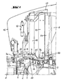
- FIG. 1 two laterally spaced side members 1, which are part of a front axle housing 2 extend fore and aft and are oriented substantially parallel to each other to form the chassis at the front end of an agricultural tractor. Only one of these side members 1 is visible in Fig. 1. An upper wishbone of a wheel suspension indicated with the reference numeral 3, which is linked to the side members 1, is also shown.
- a transmission casing 4 in which a variable transmission for driving a front power take-off shaft 5 is accommodated, is arranged between the side members 1.
- the rear part of the transmission casing 4 has its highest point roughly in the centre between the side members 1, which drops away towards the side members 1.
- radiator module 6 sits on the side members 1.
- the radiator module 6 consists of a support plate 7 as well as several coolant radiators fixed to the support plate 7.
- the support plate 7 at several places 8 is resiliently mounted on the side members 1 and secured thereto by means of bolts.
- the support plate 7 has two areas 7a and 7b at different heights.
- the area 7a is located at the front and runs closely above the transmission casing 4 whilst maintaining a narrow space therefrom, which permits unhindered assembly of the radiator module 6.
- Area 7a in this case lies higher than the rear area 7b.
- An hydraulic oil cooler 9, an intercooler 10 and a transmission oil cooler 11 are installed as coolant radiators in the front area 7a, the intercooler 10 and the transmission oil cooler 11 being arranged next to each other and behind the hydraulic oil cooler 9. Furthermore a condenser 12 for the vehicle's air conditioning system is arranged in front of the intercooler 10. The condenser 12 is mounted on the hydraulic oil cooler 9 and on the intercooler 10. A water cooler 13 with a directly fitted cooling air fan 14 is housed in the rear area 7b. This latter radiator is installed in the conventional manner with its lower coolant tank 15 on the support plate 7.
- the rear area 7b is therefore lower by the height of the lower coolant tank 15 compared to the front area 7a, so that the lower coolant tank ends at the height of the area 7a and the air sucked in by the cooling air fan 14 via the coolant radiators 9 to 11 located in front of the water cooler 13 can enter the radiator block of the water cooler 13 substantially without any detour involving heavy losses.
- All the coolant radiators and the engine (not illustrated but positioned behind the radiator module 6 on the side members 1), are closely surrounded by a bonnet 16.
- Both coolant radiators have a radiator block 17 and/or 18 of known tubular/fin construction with coolant tanks 19, 20 and/or 21, 22 in each case located at the top and bottom.
- the upper coolant tanks 19, 21 are constructed in the conventional manner and each have an inlet or outlet nozzle 23 and/or 24 for the coolant.
- the lower coolant tanks 20,22 near the support plate 7 are constructed according to the invention and differ from the above coolant tanks as described below. Since both lower coolant tanks 20, 22 are constructed in the same manner, the description is limited to that relating to the lower coolant tank 20 for the intercooler 10. It is however expressly pointed out here that lower-lying coolant tanks also of the other coolant radiators can be constructed in the same way.
- the radiator block 17 of the intercooler 10 in the outer region of its lower end is provided with a welded flange 25, which delimits a first tank part 26 of the lower coolant tank 20 assigned to the intercooler 10.
- the flange 25 possesses a number of bores, which enable the flange 25 to be fastened by means of bolts 27 to the support plate 7.
- an even counter face 7c which corresponds in shape and size to the contact surface of the flange 25, is formed on the surface of the support plate 7.
- sealing tape or a suitable gasket a pressure sealed attachment of the intercooler 10 to the support plate 7 is obtained.
- the minimum possible vertical extension of the first tank part 26 is selected, so that the radiator block 17 comes very close to the counter face 7c and the effective heat sink area of the cooler block 17 becomes as large as possible whilst the height of the upper coolant tank 19 remains the same.
- a region within the counter face 7c on the support plate 7 is provided with a recess, which forms a second tank part 28.
- First and second tank part 26 and 28 complement one another to form the fully-fledged lower coolant tank 20, whose height corresponds to that of the upper coolant tank 19.
- a second tank part 29 of the lower coolant tank 22 is formed in the support plate 7 for the transmission oil cooler 11, both tank parts 20, 22 lying in a common pan 30 and only being separated from one another by a wall 31.
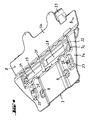
- a pipe 32 is integrated in the support plate 7 which is formed as a casting.
- Pipe 32 has an inlet/outlet connecting piece 33 which is formed at the rear of the support plate 7.
- the path of pipe 32 as it flows into the second tank part 28, can be seen from Fig. 5 and Fig. 6 and is selected having regard to vehicle components located under the support plate 7. From the latter figures it is also clear that apart from the water cooler 13 and the condenser 12, which are supplied with coolant in the usual way, all other coolant radiators 9 to 11 are attached to pipes, which likewise are integrated into the support plate 7.
- a corresponding pipe 34 leads to the second tank part 29 of the transmission oil cooler 11.
- Two further pipes 35, 36 lead to the places 37 at which the hydraulic oil cooler 9 (which has laterally spaced cooler tanks) is fixed to the support plate 7 and is connected to the pipes 35, 36 in a pressure sealed manner.
Landscapes
- Engineering & Computer Science (AREA)
- Mechanical Engineering (AREA)
- Physics & Mathematics (AREA)
- Thermal Sciences (AREA)
- General Engineering & Computer Science (AREA)
- Chemical & Material Sciences (AREA)
- Combustion & Propulsion (AREA)
- Transportation (AREA)
- Cooling, Air Intake And Gas Exhaust, And Fuel Tank Arrangements In Propulsion Units (AREA)
Applications Claiming Priority (1)
| Application Number | Priority Date | Filing Date | Title |
|---|---|---|---|
| GB0512587A GB2427459B (en) | 2005-06-21 | 2005-06-21 | Radiator module for commercial motor vehicles |
Publications (3)
| Publication Number | Publication Date |
|---|---|
| EP1736348A2 true EP1736348A2 (de) | 2006-12-27 |
| EP1736348A3 EP1736348A3 (de) | 2008-05-21 |
| EP1736348B1 EP1736348B1 (de) | 2013-10-02 |
Family
ID=34855871
Family Applications (1)
| Application Number | Title | Priority Date | Filing Date |
|---|---|---|---|
| EP06010962.6A Ceased EP1736348B1 (de) | 2005-06-21 | 2006-05-29 | Kühlereinheit für Nutzkraftfahrzeuge |
Country Status (3)
| Country | Link |
|---|---|
| US (1) | US7467679B2 (de) |
| EP (1) | EP1736348B1 (de) |
| GB (1) | GB2427459B (de) |
Cited By (5)
| Publication number | Priority date | Publication date | Assignee | Title |
|---|---|---|---|---|
| DE102006004710A1 (de) * | 2006-01-31 | 2007-08-02 | Behr Gmbh & Co. Kg | Wärmeübertrageranordnung, insbesondere eines Heckverdampfers in einem Kraftfahrzeug |
| EP1849684A3 (de) * | 2006-04-25 | 2008-05-07 | AGCO GmbH | Nutzfahrzeug, insbesondere ein landwirtschaftlicher Traktor |
| WO2015007913A1 (en) * | 2013-07-19 | 2015-01-22 | Agco International Gmbh | Vehicle cooling arrangement |
| FR3052426A1 (fr) * | 2016-06-09 | 2017-12-15 | Renault Sas | Convergent d'echangeur de chaleur comportant au moins une conduite |
| WO2019180378A1 (fr) * | 2018-03-23 | 2019-09-26 | Valeo Systemes Thermiques | Dispositif de refroidissement d'un air d'admission de moteur a combustion interne |
Families Citing this family (12)
| Publication number | Priority date | Publication date | Assignee | Title |
|---|---|---|---|---|
| US7350609B2 (en) * | 2004-06-16 | 2008-04-01 | Daikyonishikawa Corporation | Vehicle front end structure |
| DE102005039090A1 (de) * | 2005-08-06 | 2007-02-08 | Behr Gmbh & Co. Kg | Montageträgersystem |
| GB0526621D0 (en) * | 2005-12-30 | 2006-02-08 | Agco Sa | Cooler installation |
| US20090194352A1 (en) * | 2008-01-31 | 2009-08-06 | Sean Plante | Movable Side-By-Side Cooling Package |
| US8613338B2 (en) | 2010-06-18 | 2013-12-24 | Cnh America Llc | Flat plate front frame for a tractor having ballast, bumper, and tow cable connections |
| US8408344B2 (en) * | 2010-09-01 | 2013-04-02 | Toyota Motor Engineering & Manufacturing North America, Inc. | Sealing members for radiator assemblies and radiator assemblies comprising the same |
| DE102010048627A1 (de) * | 2010-10-15 | 2012-04-19 | Audi Ag | Entkoppelungselement für einen Wärmetauscher |
| JP6415890B2 (ja) | 2014-08-04 | 2018-10-31 | 株式会社クボタ | 作業車 |
| US9562464B2 (en) | 2015-05-05 | 2017-02-07 | Electro-Motive Diesel, Inc. | Modular assembly for heat exchanger |
| US20160356016A1 (en) * | 2016-08-16 | 2016-12-08 | Caterpillar Inc. | Frame for supporting a radiator guard of a machine |
| KR102567146B1 (ko) * | 2017-05-31 | 2023-08-18 | 한온시스템 주식회사 | 차량용 쿨링모듈 |
| US11353273B2 (en) * | 2019-05-01 | 2022-06-07 | Valeo North America, Inc. | Heat exchanger module and a housing therefor |
Family Cites Families (10)
| Publication number | Priority date | Publication date | Assignee | Title |
|---|---|---|---|---|
| US1355803A (en) * | 1919-07-05 | 1920-10-19 | Henry P Arndt | Cross-brace radiator-base and reservoir for motor-vehicles |
| US3989103A (en) * | 1973-04-19 | 1976-11-02 | White Motor Corporation | Method and apparatus for cooling and deaerating internal combustion engine coolant |
| DE29710887U1 (de) * | 1997-06-21 | 1997-08-14 | Paul, Uwe, 97084 Würzburg | Kühleranordnung für Kraftfahrzeuge |
| FR2805497B1 (fr) * | 2000-02-28 | 2002-06-14 | Valeo Thermique Moteur Sa | Montage d'un radiateur de refroidissement sur un support de face avant de vehicule automobile |
| JP3807204B2 (ja) * | 2000-07-27 | 2006-08-09 | 日産自動車株式会社 | ラジエータ |
| JP3695336B2 (ja) * | 2001-02-15 | 2005-09-14 | 株式会社デンソー | 熱交換器用かしめ加工装置 |
| DE60102289T2 (de) * | 2001-03-29 | 2005-03-24 | Komatsu Utility Europe S.P.A., Noventa Vicentina | Radiator für eine Erdbewegungsmaschine |
| FR2833920B1 (fr) * | 2001-12-20 | 2004-05-14 | Valeo Thermique Moteur Sa | Face avant de vehicule automobile comportant un reservoir de fluide |
| US7255189B2 (en) * | 2004-06-18 | 2007-08-14 | Cnh America Llc | Radiator mounting system |
| US7261173B2 (en) * | 2004-06-22 | 2007-08-28 | Cnh America Llc | Skid steer rear door and chassis interlock |
-
2005
- 2005-06-21 GB GB0512587A patent/GB2427459B/en not_active Expired - Fee Related
-
2006
- 2006-05-29 EP EP06010962.6A patent/EP1736348B1/de not_active Ceased
- 2006-06-21 US US11/472,487 patent/US7467679B2/en not_active Expired - Fee Related
Cited By (9)
| Publication number | Priority date | Publication date | Assignee | Title |
|---|---|---|---|---|
| DE102006004710A1 (de) * | 2006-01-31 | 2007-08-02 | Behr Gmbh & Co. Kg | Wärmeübertrageranordnung, insbesondere eines Heckverdampfers in einem Kraftfahrzeug |
| EP1849684A3 (de) * | 2006-04-25 | 2008-05-07 | AGCO GmbH | Nutzfahrzeug, insbesondere ein landwirtschaftlicher Traktor |
| US8011466B2 (en) | 2006-04-25 | 2011-09-06 | AGCO GmbH. | Utility vehicle, in particular an agricultural tractor |
| WO2015007913A1 (en) * | 2013-07-19 | 2015-01-22 | Agco International Gmbh | Vehicle cooling arrangement |
| US9616741B2 (en) | 2013-07-19 | 2017-04-11 | Agco International Gmbh | Vehicle cooling arrangement |
| EP3173272A1 (de) * | 2013-07-19 | 2017-05-31 | AGCO International GmbH | Kühlanordnung für fahrzeug |
| FR3052426A1 (fr) * | 2016-06-09 | 2017-12-15 | Renault Sas | Convergent d'echangeur de chaleur comportant au moins une conduite |
| WO2019180378A1 (fr) * | 2018-03-23 | 2019-09-26 | Valeo Systemes Thermiques | Dispositif de refroidissement d'un air d'admission de moteur a combustion interne |
| FR3079266A1 (fr) * | 2018-03-23 | 2019-09-27 | Valeo Systemes Thermiques | Dispositif de refroidissement d’un air d’admission de moteur a combustion interne |
Also Published As
| Publication number | Publication date |
|---|---|
| EP1736348B1 (de) | 2013-10-02 |
| GB2427459B (en) | 2009-11-25 |
| US20070000705A1 (en) | 2007-01-04 |
| EP1736348A3 (de) | 2008-05-21 |
| US7467679B2 (en) | 2008-12-23 |
| GB0512587D0 (en) | 2005-07-27 |
| GB2427459A (en) | 2006-12-27 |
Similar Documents
| Publication | Publication Date | Title |
|---|---|---|
| US7467679B2 (en) | Radiator module for commercial motor vehicles | |
| US5476138A (en) | Motor vehicle with improved radiator and condenser mounting device | |
| US11964550B2 (en) | Radiator system | |
| US5046554A (en) | Cooling module | |
| US8011466B2 (en) | Utility vehicle, in particular an agricultural tractor | |
| US10214247B2 (en) | Work vehicle | |
| JPH0399939A (ja) | 自動車の前部空間にある冷却空気案内装置 | |
| US10578364B2 (en) | Vehicle heat exchange apparatus | |
| EP3663549B1 (de) | Nutzfahrzeug | |
| JP4089077B2 (ja) | 熱交換器 | |
| EP2392885B1 (de) | Wärmetauscher | |
| US7694775B2 (en) | Power steering gear cooling | |
| EP2135798A1 (de) | Flüssigkeitsbehälter | |
| US20070119429A1 (en) | Vehicle working fluids cooling system | |
| KR100844506B1 (ko) | 자동차 인터쿨러의 모듈화 장착구조 | |
| US20120325427A1 (en) | Horizontal, underneath motorcycle heat exchanger | |
| JP3623918B2 (ja) | 走行車両の冷却空気流通装置 | |
| CN210217892U (zh) | 一种冷却模块结构 | |
| JPH11287585A (ja) | 熱交換器 | |
| US11760191B2 (en) | Vehicle front end module | |
| US6202602B1 (en) | Cooler for use in a vehicle combustion engine | |
| US11795844B1 (en) | Oil cooler assembly and method of improving cooling systems of all-terrain vehicle | |
| CN221892956U (zh) | 冷却系统的减振安装结构及具有其的农业机械 | |
| JP2025088479A (ja) | 作業車両 | |
| PL199496B1 (pl) | Chłodnica do pojazdów silnikowych |
Legal Events
| Date | Code | Title | Description |
|---|---|---|---|
| PUAI | Public reference made under article 153(3) epc to a published international application that has entered the european phase |
Free format text: ORIGINAL CODE: 0009012 |
|
| AK | Designated contracting states |
Kind code of ref document: A2 Designated state(s): AT BE BG CH CY CZ DE DK EE ES FI FR GB GR HU IE IS IT LI LT LU LV MC NL PL PT RO SE SI SK TR |
|
| AX | Request for extension of the european patent |
Extension state: AL BA HR MK YU |
|
| PUAL | Search report despatched |
Free format text: ORIGINAL CODE: 0009013 |
|
| AK | Designated contracting states |
Kind code of ref document: A3 Designated state(s): AT BE BG CH CY CZ DE DK EE ES FI FR GB GR HU IE IS IT LI LT LU LV MC NL PL PT RO SE SI SK TR |
|
| AX | Request for extension of the european patent |
Extension state: AL BA HR MK YU |
|
| RIC1 | Information provided on ipc code assigned before grant |
Ipc: B62D 25/08 20060101ALI20080416BHEP Ipc: B60K 11/04 20060101AFI20061017BHEP Ipc: F28F 9/00 20060101ALI20080416BHEP Ipc: F28F 9/02 20060101ALI20080416BHEP |
|
| 17P | Request for examination filed |
Effective date: 20081121 |
|
| 17Q | First examination report despatched |
Effective date: 20090107 |
|
| AKX | Designation fees paid |
Designated state(s): DE FR GB IT |
|
| GRAP | Despatch of communication of intention to grant a patent |
Free format text: ORIGINAL CODE: EPIDOSNIGR1 |
|
| RIC1 | Information provided on ipc code assigned before grant |
Ipc: F28F 9/00 20060101ALI20130228BHEP Ipc: F28D 1/04 20060101ALI20130228BHEP Ipc: B62D 25/08 20060101ALI20130228BHEP Ipc: B60K 11/04 20060101AFI20130228BHEP |
|
| GRAS | Grant fee paid |
Free format text: ORIGINAL CODE: EPIDOSNIGR3 |
|
| GRAA | (expected) grant |
Free format text: ORIGINAL CODE: 0009210 |
|
| AK | Designated contracting states |
Kind code of ref document: B1 Designated state(s): DE FR GB IT |
|
| REG | Reference to a national code |
Ref country code: GB Ref legal event code: FG4D |
|
| REG | Reference to a national code |
Ref country code: DE Ref legal event code: R096 Ref document number: 602006038633 Country of ref document: DE Effective date: 20131128 |
|
| REG | Reference to a national code |
Ref country code: DE Ref legal event code: R097 Ref document number: 602006038633 Country of ref document: DE |
|
| PLBE | No opposition filed within time limit |
Free format text: ORIGINAL CODE: 0009261 |
|
| STAA | Information on the status of an ep patent application or granted ep patent |
Free format text: STATUS: NO OPPOSITION FILED WITHIN TIME LIMIT |
|
| 26N | No opposition filed |
Effective date: 20140703 |
|
| REG | Reference to a national code |
Ref country code: DE Ref legal event code: R097 Ref document number: 602006038633 Country of ref document: DE Effective date: 20140703 |
|
| PGFP | Annual fee paid to national office [announced via postgrant information from national office to epo] |
Ref country code: GB Payment date: 20150521 Year of fee payment: 10 |
|
| PGFP | Annual fee paid to national office [announced via postgrant information from national office to epo] |
Ref country code: IT Payment date: 20150511 Year of fee payment: 10 |
|
| REG | Reference to a national code |
Ref country code: FR Ref legal event code: PLFP Year of fee payment: 11 |
|
| GBPC | Gb: european patent ceased through non-payment of renewal fee |
Effective date: 20160529 |
|
| PG25 | Lapsed in a contracting state [announced via postgrant information from national office to epo] |
Ref country code: IT Free format text: LAPSE BECAUSE OF NON-PAYMENT OF DUE FEES Effective date: 20160529 |
|
| REG | Reference to a national code |
Ref country code: FR Ref legal event code: PLFP Year of fee payment: 12 |
|
| PG25 | Lapsed in a contracting state [announced via postgrant information from national office to epo] |
Ref country code: GB Free format text: LAPSE BECAUSE OF NON-PAYMENT OF DUE FEES Effective date: 20160529 |
|
| REG | Reference to a national code |
Ref country code: FR Ref legal event code: PLFP Year of fee payment: 13 |
|
| PGFP | Annual fee paid to national office [announced via postgrant information from national office to epo] |
Ref country code: DE Payment date: 20180522 Year of fee payment: 13 |
|
| PGFP | Annual fee paid to national office [announced via postgrant information from national office to epo] |
Ref country code: FR Payment date: 20180522 Year of fee payment: 13 |
|
| REG | Reference to a national code |
Ref country code: DE Ref legal event code: R119 Ref document number: 602006038633 Country of ref document: DE |
|
| PG25 | Lapsed in a contracting state [announced via postgrant information from national office to epo] |
Ref country code: DE Free format text: LAPSE BECAUSE OF NON-PAYMENT OF DUE FEES Effective date: 20191203 |
|
| PG25 | Lapsed in a contracting state [announced via postgrant information from national office to epo] |
Ref country code: FR Free format text: LAPSE BECAUSE OF NON-PAYMENT OF DUE FEES Effective date: 20190531 |