EP1736331A1 - Ausrichthilfsvorrichtung für Anhänger - Google Patents
Ausrichthilfsvorrichtung für Anhänger Download PDFInfo
- Publication number
- EP1736331A1 EP1736331A1 EP06011323A EP06011323A EP1736331A1 EP 1736331 A1 EP1736331 A1 EP 1736331A1 EP 06011323 A EP06011323 A EP 06011323A EP 06011323 A EP06011323 A EP 06011323A EP 1736331 A1 EP1736331 A1 EP 1736331A1
- Authority
- EP
- European Patent Office
- Prior art keywords
- wheel
- link
- assembly
- lever
- axle
- Prior art date
- Legal status (The legal status is an assumption and is not a legal conclusion. Google has not performed a legal analysis and makes no representation as to the accuracy of the status listed.)
- Withdrawn
Links
- 230000002093 peripheral effect Effects 0.000 claims abstract description 19
- 238000000034 method Methods 0.000 claims abstract description 10
- 238000003780 insertion Methods 0.000 claims description 7
- 230000037431 insertion Effects 0.000 claims description 7
- 230000000295 complement effect Effects 0.000 claims description 3
- 239000000463 material Substances 0.000 claims description 3
- 230000008878 coupling Effects 0.000 claims description 2
- 238000010168 coupling process Methods 0.000 claims description 2
- 238000005859 coupling reaction Methods 0.000 claims description 2
- 230000007246 mechanism Effects 0.000 description 9
- 238000010586 diagram Methods 0.000 description 6
- 229910000975 Carbon steel Inorganic materials 0.000 description 1
- 230000009471 action Effects 0.000 description 1
- 230000015572 biosynthetic process Effects 0.000 description 1
- 229910052799 carbon Inorganic materials 0.000 description 1
- 239000010962 carbon steel Substances 0.000 description 1
- 230000008859 change Effects 0.000 description 1
- 239000011248 coating agent Substances 0.000 description 1
- 238000000576 coating method Methods 0.000 description 1
- 230000000694 effects Effects 0.000 description 1
- 238000011065 in-situ storage Methods 0.000 description 1
- 238000004519 manufacturing process Methods 0.000 description 1
- 230000004048 modification Effects 0.000 description 1
- 238000012986 modification Methods 0.000 description 1
- 230000008569 process Effects 0.000 description 1
- 238000010008 shearing Methods 0.000 description 1
- 238000003860 storage Methods 0.000 description 1
Images




Classifications
-
- B—PERFORMING OPERATIONS; TRANSPORTING
- B60—VEHICLES IN GENERAL
- B60D—VEHICLE CONNECTIONS
- B60D1/00—Traction couplings; Hitches; Draw-gear; Towing devices
- B60D1/58—Auxiliary devices
- B60D1/66—Props
-
- B—PERFORMING OPERATIONS; TRANSPORTING
- B60—VEHICLES IN GENERAL
- B60S—SERVICING, CLEANING, REPAIRING, SUPPORTING, LIFTING, OR MANOEUVRING OF VEHICLES, NOT OTHERWISE PROVIDED FOR
- B60S9/00—Ground-engaging vehicle fittings for supporting, lifting, or manoeuvring the vehicle, wholly or in part, e.g. built-in jacks
- B60S9/14—Ground-engaging vehicle fittings for supporting, lifting, or manoeuvring the vehicle, wholly or in part, e.g. built-in jacks for both lifting and manoeuvring
- B60S9/16—Ground-engaging vehicle fittings for supporting, lifting, or manoeuvring the vehicle, wholly or in part, e.g. built-in jacks for both lifting and manoeuvring for operating only on one end of vehicle
- B60S9/18—Ground-engaging vehicle fittings for supporting, lifting, or manoeuvring the vehicle, wholly or in part, e.g. built-in jacks for both lifting and manoeuvring for operating only on one end of vehicle mechanically
Definitions
- the present invention relates to an alignment aid for the manual alignment of the towing hitch of a trailer, caravan, boat trailer, horse float or the like with the tow-ball of a vehicle,
- the present invention relates to a trailer alignment apparatus suited to a jockey wheel assembly which temporarily supports the towing hitch of the trailer.
- the wheel assembly is provided to facilitate movement of the trailer over relatively short distances.
- the wheel assembly typically includes a raising and lowering mechanism for both levelling of the trailer, and the engagement of and/or removal of the towing hitch from the tow-ball.
- WO 2004037567 entitled 'Jockey Wheel Assembly' which describes a jockey wheel assembly having a drive system including a crank coupled to a rotatable shaft which is inturn coupled to the wheel hub. Rotation of the crank causes rotation of the shaft, this rotation then being translated into linear movement by the wheel, in a forward or reverse direction depending on the direction of rotation of the crank.
- the assembly is also provided with a tiller which enables the user to control the direction the wheel is facing and thus control the direction of movement of the trailer.
- the problem with such an arrangement is that it utilises a number of gears and these gears under the strain of moving such large loads are prone to wear, sheering and slippage, which can lead to a momentarily loss of control over the trailer. This momentary loss of control may be all that is required to cause the trailer to freewheel.
- the assembly includes a frame mountable on a trailer, a wheel frame and a lever arm.
- the lever includes a ratchet arm which mates with a corresponding pawl mounted on the frame.
- the pawls being operable upon pivotal movement of the lever to selectively move or restrain rotation of the wheel in the frame.
- the tyre of the jockey wheel is prone to slip on the wheel hub when the hub is mechanically driven. Such a slippage again can lead to the trailer freewheeling. If the tyre is a pneumatic tyre this slippage can tear out the valve stem leading to deflation of the tyre requiring the replacement of the stem or entire inner tube.
- an apparatus for manoeuvring a trailer having a jockey wheel assembly a ground engaging wheel rotatably mounted on an axle said apparatus characterised by:
- a jockey wheel assembly including a ground engaging wheel rotatably mounted on an axle, said method characterised by the steps of:
- a method of manoeuvring a trailer having a jockey wheel assembly including a ground engaging wheel rotatably mounted on an axle said method characterised by the steps of:
- an alignment apparatus for manoeuvring a trailer having jockey wheel assembly including a ground engaging wheel rotatably mounted on a hollow axle, said apparatus characterised by:
- the lever assembly includes a handle and a wheel engagement portion disposed at one end of the handle.
- the lever assembly may be manufactured from high grade carbon steel, or other such suitable material capable of withstanding the shear forces generated during movement of a heavily laden trailer or the like.
- the handle has a plurality of apertures disposed at a predetermined distance from the pad.
- the wheel engagement portion may be in the form of a pad.
- the pad may be any suitable closed shape such as a square, rectangle, hexagon, pentagon, triangle or circle. Most preferably the pad is substantially circular in shape.
- the pad may be coated with a material having a relatively high co-efficient of friction such as vulcanised rubber or the like.
- the pad may be provided with a formation, such as series of grooves that match the shape of the peripheral surface wheel to further increase the frictional engagement therebetween.
- the wheel engagement portion may take the form of a tooth or the like wherein said tooth is shaped for complementary engagement with the peripheral surface of the wheel.
- the peripheral surface of the wheel is in the form of a treaded tyre.
- the link member is pivotally mounted on the outside of the wheel assembly, or on the inside wheel assembly between the wheel mount and the wheel by any suitable fastening means such as a bolt or cotter pin.
- the link is mounted adjacent the axle
- the link is mounted on the axle of the wheel assembly.
- the link is a single elongate member.
- the link may be formed from a plurality of interlinked members.
- the link may include one or more mounting plates secured the end of the link.
- the link member is preferably in the form of a rigid C-shaped bar wherein one arm is coupled to the lever assembly and the remaining arm is adapted for insertion into the hollow axle.
- the link extends about a portion of the wheel forming a space therebetween into which the lever can be inserted.
- the link may have a pin slideably mounted thereon, said pin being inserted into one of the plurality of apertures provided in the handle, to thereby secure the lever assembly to the link in a removable manner.
- the link may extend from the frame adjacent the wheel, the lever then being positioned on the wheel and adjacent the link.
- the link may also include a plurality of apertures through which a pin may be inserted, the pin then being passed through a corresponding aperture provided on the handle of the lever assembly, to thereby secure the lever assembly to the link in a removable manner.
- the apparatus may further include a breaking assembly mounted on the frame that is selectively engagable with the peripheral surface wheel.
- the braking assembly includes a brace and a plate.
- the plate may include a tail for engagement with the brace and a tip for engagement with the peripheral surface wheel.
- the plate is positioned within the wheel mount.
- the brace may include a lever coupled to a pin.
- the pin is U-shaped with one arm of said U passing through the wheel mount.
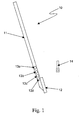
- the lever 10 for an alignment apparatus of the present invention.
- the lever includes handle 11 and pad 12 and a plurality of apertures 13a-d disposed along the handle at varying locations. Apertures 13a-d are provided so as to allow a pin 14 to be inserted therethrough. Pin 14 is adapted to pass through an aperture 21 in link 20 (see FIGs 2 and 7A) thereby securing the lever 10 in a removable manner to link 20.
- the amount of purchase on the tyre 39 of the wheel 33 imparted by lever 10 is proportional to the distance of the pad to the aperture 13a-d at which the pin 14 is inserted. For example the maximum available purchase is provided when the pin 14 is inserted into the furthermost aperture 13a.
- Pad 12 may be any suitable shape such as a square, rectangular, hexagonal, pentagonal or circular. However the pad 12 is most preferably substantially circular in shape. Providing a circularly shaped pad allows the lever 10 to be utilised through a wider range of angles ⁇ to the vertical (see Fig 6). This is particularly the case as discussed below in relation to FIG 6 when the link is in the form of a tensile cable 23.
- the pad may be provided with a frictional coating on its engagement face in order to increase the amount friction between the pad 12 and wheel 33 when engaged, thereby further increasing the amount of purchase on the wheel 33 during the lever's movement stroke.
- the face of the pad 12 may be provided with a series of grooves that match or at least co-operate with the peripheral surface of the wheel 33. Upon engagement the pad with the wheel 33 the pad 12 is inserted within the corresponding groove thereby further increasing the amount of purchase on the wheel 33 during the movement stroke.
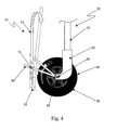
- FIG. 2 depicts the trailer alignment apparatus of one embodiment of the present invention positioned on a jockey wheel assembly 30 which is attached to the traifer's A frame (not shown).
- the wheel assembly 30 includes wheel 33 having a treaded tyre 39 supported on axle 34 within a wheel mount 32 and an extendable support 31.
- Link 20 is pivotally mounted at point 22 on wheel mount 32 adjacent the axle 34.
- lever 10 is positioned adjacent the link 20 with pad 12 engaging the periphery of wheel 33, namely the treaded surface of tyre 39.
- Pin 14 is then inserted through aperture 21 in link 20 into one of the corresponding apertures 13a-d in handle 11 (in this instance aperture 13b).
- lever 10 may also be used to brake the wheel 33.
- pad 12 By applying a sufficient downward force on handle 11, pad 12 is wedged against the tyre 39 forcing it against the hub preventing movement of wheel 33. Applying this type of braking to the wheel 33 steadies the trailer and reduces unwanted movement until the wheels of the trailer can be chocked. Once the chocks are in position the force may be released from handle 11 thereby disengaging pad 12 from wheel 33. The lever 10 and link 20 may then be returned to their initial position ready for the next downward stroke 35 as discussed above.
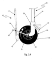
- the jockey wheel assembly may alternatively be fitted with braking mechanism 37 as shown in FIG. 5A.
- the braking mechanism is engaged with the wheel 33 prior to removal of pad 12.
- brake 37 Upon re-engagement of the pad 12 with wheel 33 at the top of the movement stroke (shown in dashed outline) brake 37 is released, and handle 11 drawn downward to impart movement of wheel 33 in the desired direction 36.
- FIGs 5B to 5F illustrate another possible arrangement of the braking mechanism for use with the alignment aid of the present invention.
- the braking mechanism includes a brace 40 and plate 38 which in the present case is positioned within the wheel mount 32.
- Brace 40 is includes a lever 41 which is coupled U-shaped pin 42.
- the plate 38 as shown includes a tail 45 for engagement with the brace, a tip 44 for engagement with the surface of the tyre 29. The tip being connected to the main body of the plate 38 via neck 43.
- the braking mechanism is shown in the locked position with tail 45 positioned over both arms of the u-shaped pin 42, In this position the main body of the plate 38 is free to rest upon the tyre 29 with the tip being elevated above the tyre 29 see FIG 5C.
- the breaking mechanism allows the wheel to move in the forward direction only. Any movement of the wheel in the opposing direction forces the plate 38 back toward the wheel mount 32 forcing tail 45 away from the external arm 42a of pin 42 see FIG 5B. This causes the neck 43 to engage the wheel mount 32 forcing tip 44 to bite down onto the surface of the tyre 29 thereby braking the wheel 33.
- FIGs 5D to 5F illustrate the various stages of releasing the brake mechanism to enable free motion of the wheel 33.
- the lever 41 of brace 40 is drawn upward forcing the external arm 42a of pin 42 downward and away from plate 38 (FIG 5E).
- Plate 38 may then be manually drawn forward so that the tail 45 engages the internal arm 42b (not pictured) of the pin 42.
- Lever 41 is then pushed downward to its lowest most extent positioning the external arm 42a against the wheel mount 32 and drawing the internal arm 42b of pin 42 into engagement with tail 45 thereby wedging the plate against the stirrup of the wheel mount 32.
- This wedging action intum raise the remainder of the plate including the neck 43 and tip 44 clear of the surface of the tyre 29 allowing wheel 33 to run free (see FIG 5G and 5F).
- link 20 is in the form of a tensile cable 23 coupled to mounting plates 22.
- the plates 22 are mounted on the axle 34 between the wheel mount 32 and wheel 33 such that cable 23 extends between opposite ends of the axle 34 and is positioned about the wheel 33 creating a space 38 therebetween.
- Pin 14 is slidably mounted on the cable 23. in operation lever 10 is positioned in the space 38 between the cable 23 and the wheel 33. Pin 14 is then inserted into the desired aperture 13a-d thereby removably securing lever 10 to link 20.
- Lever 10 may then be engaged with the wheel 33 in the manner discussed above in order to move wheel 33 in the desired direction.
- the position of the lever can be varied from vertical through a range of angles ⁇ as illustrated by the lever positions shown in broken lines. Accordingly the user need not be directly in front of the jockey wheel assembly in order to use the lever 10 but can be to one side of the jockey wheel without a losing purchase on wheel 33.
- FIGs 7A to 7C illustrate in greater detail a number of possible configurations of the link 20.
- FIG 7A depicts a rigid link 20 in the form of a single bar 23 not unlike that discussed above in relation to FIGs 2 to 5.
- Bar 23 includes a number of apertures 21 a-c through which pin 14 can be inserted, this enables the position at which lever 10 is secured to the bar 23 to be selectively varied.
- Bar 23 also includes a mounting aperture 22 via which the link 20 is pivotally mounted to the wheel mount 32 or on axle 34 and is held in position by a suitable fastening means such as a bolt, cotter pin or CER-clip.
- FIG 7B shows the link 20 in this instance in the form of rigid U or C shaped bracket 23, upon which pin 14 is slidably mounted.
- the bracket 23 includes mounting apertures 22 via which the link 20 is pivotally mounted to the wheel mount 32 or on the axle 34 by a suitable fastening means.
- FIG 7C depicts a flexible link 20 in the form of a tensile cable 23.
- Cable 23 is attached to a pair of mounting plates 22 having apertures 24 via which the link 20 is pivotally mounted on the axle 34 of wheel 33.
- the cable 23 may be attached to the mounting plates 22 via any suitable means e.g. the ends may be swagged to the plates.
- An alternative arrangement for mounting the cable 23 to the axle 34 is the simply for a loop at end these loops are then secured back to the main cable 23 by a swagged connector.
- Figs 8A to 8C illustrate a further embodiment of the alignment apparatus of the present invention.
- the link 20 is in the form of a rigid C shaped bar with end 20a coupled to the lever 10 at a predetermined distance from the wheel engagement portion 12.
- End 20b of the link 20 is adapted to be pivotally mounted within hollow axle 34.
- Lever 10 is secured to link in such a manner so as to enable the lever 10 to be pivoted about end 20a.
- the wheel engagement portion 12 in this particular case includes at least one tooth 12a, said tooth being shaped for complementary engagement with the peripheral surface 39 of the wheel 33.
- link 20 and lever 10 are designed to be removable from the jockey wheel assembly. As lever 10 can be pivoted about end 20a the link 20 may be conveniently fold against the lever 10 for easy of storage.
- Fig 8B shows the link 20 and lever 10 mounted in situ on the jockey wheel assembly with end 20b being mounted within hollow axle 34. Applying a driving force 35 in the direction of arrow 35 cases the tooth 12a of wheel engagement portion 12 to grip the tyre 39 rotating the wheel in the direction of arrow 36.
- Fig 8C shows the reverse angle of the apparatus as shown in Fig 8B by applying a lateral force in either of the directions indicated by arrow 82 directs the wheel in a desired direction of travel.
- a driving force is applied in the direction of arrow 35 cases the tooth 12a of wheel engagement portion 12 to grip the tyre 39 to rotate the wheel to thereby move the trailer in the desired direction of travel.
- a force is applied in the direction of arrow 81 causing lever 10 to pivot about end 20a of link 20 thereby releasing tooth 12a from tyre 39.
- a user may then change the direction of the tyre if required or simply return the lever to the top of the drive stroke if further movement in the desired direction is required.
Landscapes
- Engineering & Computer Science (AREA)
- Mechanical Engineering (AREA)
- Transportation (AREA)
- Handcart (AREA)
Applications Claiming Priority (1)
| Application Number | Priority Date | Filing Date | Title |
|---|---|---|---|
| AU2005902847A AU2005902847A0 (en) | 2005-06-02 | Alignment aid |
Publications (1)
| Publication Number | Publication Date |
|---|---|
| EP1736331A1 true EP1736331A1 (de) | 2006-12-27 |
Family
ID=37038484
Family Applications (1)
| Application Number | Title | Priority Date | Filing Date |
|---|---|---|---|
| EP06011323A Withdrawn EP1736331A1 (de) | 2005-06-02 | 2006-06-01 | Ausrichthilfsvorrichtung für Anhänger |
Country Status (2)
| Country | Link |
|---|---|
| US (1) | US7726679B2 (de) |
| EP (1) | EP1736331A1 (de) |
Cited By (1)
| Publication number | Priority date | Publication date | Assignee | Title |
|---|---|---|---|---|
| EP4183692A1 (de) * | 2021-11-22 | 2023-05-24 | Gulfstream Aerospace Corporation | Anpassungswerkzeug für bugfahrwerk |
Families Citing this family (7)
| Publication number | Priority date | Publication date | Assignee | Title |
|---|---|---|---|---|
| AU2009212966B1 (en) * | 2009-09-07 | 2009-12-24 | Damien Jon Rossow | Vehicle jockey wheel |
| US20110101645A1 (en) * | 2009-11-02 | 2011-05-05 | Williams Jr Thomas M | Teleswivel Hitch Apparatus |
| US8925954B2 (en) | 2010-03-09 | 2015-01-06 | Teleswivel, Llc | Hitch apparatus for vehicles |
| US8302987B2 (en) | 2010-11-04 | 2012-11-06 | Williams Innovations, Llc | Adjustable towing apparatus for vehicles |
| US20150314886A1 (en) * | 2013-10-15 | 2015-11-05 | Nicholas R. Guida | Leverage activated aircraft tow bar |
| US20150266406A1 (en) * | 2014-02-25 | 2015-09-24 | Duane Stombaugh | Trailer mover |
| US20220396105A1 (en) * | 2021-06-09 | 2022-12-15 | Duane Stombaugh | Trailer Moving Assist Device |
Citations (8)
| Publication number | Priority date | Publication date | Assignee | Title |
|---|---|---|---|---|
| US2994541A (en) * | 1960-04-21 | 1961-08-01 | John A Dobbins | Airplane tow bar |
| US3482847A (en) * | 1968-01-30 | 1969-12-09 | Marvin N Hart | Trailer guide wheel construction |
| US3738672A (en) * | 1971-09-20 | 1973-06-12 | V Dalton | Dolly for moving vehicles |
| US4470564A (en) * | 1983-03-17 | 1984-09-11 | Johnson Phillip L | Tug |
| US4883280A (en) * | 1988-06-16 | 1989-11-28 | Christian Fredrick W | Towbar and come-along for light aircraft |
| US5338047A (en) * | 1992-07-22 | 1994-08-16 | Knisley Glenn E | Trailer alignment device |
| AU2002100165A4 (en) | 2002-03-05 | 2002-04-11 | Ark Engineering Pty Ltd | Jockey wheel |
| WO2004037567A1 (en) | 2002-10-26 | 2004-05-06 | Purple Line Limited | Jockey wheel assembly |
Family Cites Families (11)
| Publication number | Priority date | Publication date | Assignee | Title |
|---|---|---|---|---|
| US3937479A (en) * | 1972-03-30 | 1976-02-10 | Dalton Virgil D | Dolly for moving and positioning vehicles |
| US3826324A (en) * | 1972-10-26 | 1974-07-30 | D Stevens | Trailer mover |
| AU499576B2 (en) * | 1976-06-21 | 1979-04-26 | Roseglen Holdings Pty Ltd | Moving jockey wheel |
| ZA7934B (en) * | 1978-01-11 | 1979-12-27 | L Morris | Traction devices for towed vehicles |
| DE3443164A1 (de) | 1984-11-27 | 1985-06-27 | Brigitte 4400 Münster Heßling | Stuetzrad mit antrieb |
| US5501482A (en) * | 1993-09-28 | 1996-03-26 | Mcclive; William J. | Wheel coupling for attaching a vehicular device to a wheel of an automotive vehicle |
| NL1018798C1 (nl) | 2001-08-22 | 2001-10-09 | Jan Hendrik Visscher | Caravan-Hand-Verplaatser (C.H.V.). |
| SE525130C2 (sv) * | 2003-01-31 | 2004-12-07 | Bt Ind Ab | Ledarmstruck med kraftöverförande organ och koppling för överförande av en pumpande ledarmsrörelse till en drivrörelse för styrhjulen |
| US7036840B2 (en) * | 2004-04-01 | 2006-05-02 | Kwilinski Christopher M | Trailer alignment apparatus |
| US6990745B1 (en) * | 2004-04-05 | 2006-01-31 | Schoenenberger Dennis W | Trailer hitch alignment system |
| US20070205580A1 (en) * | 2006-03-01 | 2007-09-06 | Hamilton Marine Llc | Trailer hitch |
-
2006
- 2006-05-31 US US11/421,130 patent/US7726679B2/en not_active Expired - Fee Related
- 2006-06-01 EP EP06011323A patent/EP1736331A1/de not_active Withdrawn
Patent Citations (8)
| Publication number | Priority date | Publication date | Assignee | Title |
|---|---|---|---|---|
| US2994541A (en) * | 1960-04-21 | 1961-08-01 | John A Dobbins | Airplane tow bar |
| US3482847A (en) * | 1968-01-30 | 1969-12-09 | Marvin N Hart | Trailer guide wheel construction |
| US3738672A (en) * | 1971-09-20 | 1973-06-12 | V Dalton | Dolly for moving vehicles |
| US4470564A (en) * | 1983-03-17 | 1984-09-11 | Johnson Phillip L | Tug |
| US4883280A (en) * | 1988-06-16 | 1989-11-28 | Christian Fredrick W | Towbar and come-along for light aircraft |
| US5338047A (en) * | 1992-07-22 | 1994-08-16 | Knisley Glenn E | Trailer alignment device |
| AU2002100165A4 (en) | 2002-03-05 | 2002-04-11 | Ark Engineering Pty Ltd | Jockey wheel |
| WO2004037567A1 (en) | 2002-10-26 | 2004-05-06 | Purple Line Limited | Jockey wheel assembly |
Cited By (1)
| Publication number | Priority date | Publication date | Assignee | Title |
|---|---|---|---|---|
| EP4183692A1 (de) * | 2021-11-22 | 2023-05-24 | Gulfstream Aerospace Corporation | Anpassungswerkzeug für bugfahrwerk |
Also Published As
| Publication number | Publication date |
|---|---|
| US20070029757A1 (en) | 2007-02-08 |
| US7726679B2 (en) | 2010-06-01 |
Similar Documents
| Publication | Publication Date | Title |
|---|---|---|
| EP0317044B1 (de) | Vorrichtung und Verfahren zum Heben und Transportieren eines Kraftfahrzeug-Wechselrades | |
| US4300252A (en) | Wheel support for bow end of a boat | |
| EP1982881A1 (de) | Vorrichtung zur Immobilisierung eines Fahrzeugrades und Verfahren zur Immobilisierung eines Fahrzeugrades | |
| US7726679B2 (en) | Trailer alignment apparatus | |
| US3801137A (en) | Automatic releasing backing device for truck dolly | |
| US5366171A (en) | Vehicle mounted reel lifting, driving and braking apparatus | |
| AU2006202332B2 (en) | Trailer alignment apparatus | |
| US2116825A (en) | Container for the transport of merchandise | |
| US7325822B1 (en) | Trailer tandem release handle tool | |
| US3779579A (en) | Wheel mounting assembly | |
| AU2007237358A1 (en) | Trailer alignment apparatus | |
| US6857176B2 (en) | Tandem wheel unlocking assist device | |
| WO2014017926A1 (en) | Chain tensioning device | |
| DE646052C (de) | Bodenbremse fuer Kraftfahrzeuge | |
| US20080106064A1 (en) | Tractor trailer dolly jockey | |
| EP1038740B1 (de) | Bremsvorrichtung für Anhänger mit Stützrad | |
| EP1806245B1 (de) | Anhängerkupplungsvorrichtung | |
| DE196412C (de) | ||
| DE256271C (de) | ||
| DE105988C (de) | ||
| DE49334C (de) | Bremse für Strafsenfuhrwerke, bei welcher die Bremsbacken auch als Hemmschuhe wirken können | |
| DE49227C (de) | Durch Zurückziehen der Zügelleine befhätigte Bremse für Strafsenfuhrwerke | |
| DE729038C (de) | Bremsvorrichtung fuer durch Zugtiere gezogene Strassenfahrzeuge | |
| DE99177C (de) | ||
| US2849136A (en) | Boat trailer |
Legal Events
| Date | Code | Title | Description |
|---|---|---|---|
| PUAI | Public reference made under article 153(3) epc to a published international application that has entered the european phase |
Free format text: ORIGINAL CODE: 0009012 |
|
| AK | Designated contracting states |
Kind code of ref document: A1 Designated state(s): AT BE BG CH CY CZ DE DK EE ES FI FR GB GR HU IE IS IT LI LT LU LV MC NL PL PT RO SE SI SK TR |
|
| AX | Request for extension of the european patent |
Extension state: AL BA HR MK YU |
|
| 17P | Request for examination filed |
Effective date: 20070627 |
|
| AKX | Designation fees paid |
Designated state(s): AT BE BG CH CY CZ DE DK EE ES FI FR GB GR HU IE IS IT LI LT LU LV MC NL PL PT RO SE SI SK TR |
|
| 17Q | First examination report despatched |
Effective date: 20090828 |
|
| RTI1 | Title (correction) |
Free format text: TRAILER ALIGNMENT APPARATUS |
|
| STAA | Information on the status of an ep patent application or granted ep patent |
Free format text: STATUS: THE APPLICATION IS DEEMED TO BE WITHDRAWN |
|
| 18D | Application deemed to be withdrawn |
Effective date: 20120103 |