EP1736074B1 - Verbesserter Rucksack - Google Patents
Verbesserter Rucksack Download PDFInfo
- Publication number
- EP1736074B1 EP1736074B1 EP05013246A EP05013246A EP1736074B1 EP 1736074 B1 EP1736074 B1 EP 1736074B1 EP 05013246 A EP05013246 A EP 05013246A EP 05013246 A EP05013246 A EP 05013246A EP 1736074 B1 EP1736074 B1 EP 1736074B1
- Authority
- EP
- European Patent Office
- Prior art keywords
- back side
- pack
- sheet frame
- backpack according
- frame
- Prior art date
- Legal status (The legal status is an assumption and is not a legal conclusion. Google has not performed a legal analysis and makes no representation as to the accuracy of the status listed.)
- Active
Links
Images


Classifications
-
- A—HUMAN NECESSITIES
- A45—HAND OR TRAVELLING ARTICLES
- A45F—TRAVELLING OR CAMP EQUIPMENT: SACKS OR PACKS CARRIED ON THE BODY
- A45F3/00—Travelling or camp articles; Sacks or packs carried on the body
- A45F3/04—Sacks or packs carried on the body by means of two straps passing over the two shoulders
- A45F3/08—Carrying-frames; Frames combined with sacks
-
- A—HUMAN NECESSITIES
- A45—HAND OR TRAVELLING ARTICLES
- A45F—TRAVELLING OR CAMP EQUIPMENT: SACKS OR PACKS CARRIED ON THE BODY
- A45F3/00—Travelling or camp articles; Sacks or packs carried on the body
- A45F3/04—Sacks or packs carried on the body by means of two straps passing over the two shoulders
- A45F2003/045—Sacks or packs carried on the body by means of two straps passing over the two shoulders and one additional strap around the waist
-
- A—HUMAN NECESSITIES
- A45—HAND OR TRAVELLING ARTICLES
- A45F—TRAVELLING OR CAMP EQUIPMENT: SACKS OR PACKS CARRIED ON THE BODY
- A45F3/00—Travelling or camp articles; Sacks or packs carried on the body
- A45F3/04—Sacks or packs carried on the body by means of two straps passing over the two shoulders
- A45F3/047—Sacks or packs carried on the body by means of two straps passing over the two shoulders with adjustable fastenings for the shoulder straps or waist belts
Definitions
- the invention relates to packs, more specifically to backpacks.
- Backpacks usually comprise a pack portion, usually made of relatively flexible (i.e. non-rigid) materials such as panels of textiles fabrics, which forms a compartment adapted to receive a load to be carried.
- the pack portion comprises a back side which is positioned opposite the back of the user when it is worn.
- the backpack also has a carrying system which can comprise a pair of shoulder straps and possibly a hip-belt.
- a loaded backpack Being made of flexible materials, a loaded backpack tends to deform due to the volume and/or the weight of the load inside the pack. Especially, the back side can deform, which is most uncomfortable to the user.
- the backpack In order to prevent at least partly such unwanted deformation, it is known to provide the backpack with a stiffening frame along its back side.
- Such frames may be of different kinds.
- Some packs are equipped with one or more rigid rods (or stays) which are inserted in gussets attached to the back side. These rods are usually made of metal, plastic or composite material, and they run substantially vertically along the back side.
- Other packs have a frame made of a sheet of semi-rigid or rigid material which is inserted in a gusset pocket of corresponding shape attached to the back side (usually on the inner side of the back side).
- Such sheet frame can be made of various materials, including plastic, composite materials or rigid or semi-rigid foams. In the latter case, it can be provided that the sheet frame of semi-rigid foam is made of a folded sheet which is removably inserted in the gusset pocket and which can be removed to be used as sleeping mattress for outdoor sports enthusiasts.
- a sheet frame can also be reinforced by removable or non removable rigid rods, and it can also be complemented by a layer of soft foam to provide additional carrying comfort to the user.
- the carrying system is made to shift at least part of the weight of the load off the shoulder straps, down to the hip-belt, in order that at least part of the weight of the load is carried by the hips of the user rather than having his shoulders and his back carry all the load.
- the stiffening frame participates in that load transfer by making a link between the shoulder strap attachment portions of the pack portion and its hip-belt attachment portions.
- US patent 4.750.654 is shown a backpack wherein the flexible pack portion has no back side, the back side being made of layered structure comprising two layers of cellular synthetic resins (i.e. foams) over-moulded on a fabric layer.
- the flexible pack portion is sewn on the outer periphery of the back side structure.
- Gluing requires the provision of an adhesive material between the two pieces to be assembled, whereas welding means that the surface of at least one of the pieces to be assembled (but preferably both) is melted to adhesively bond the two pieces. Both welding and gluing result in an adhesive bonding of the two pieces.
- a backpack having:
- the sheet frame is adhesively bonded to an inner surface of the back side of the pack portion, or to its outer surface.
- the carrying system can be indirectly connected to pack portion via the sheet frame.
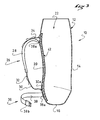
- a backpack 10 according to the invention, that is, a pack which is designed to be carried along the back of a user.
- This backpack 10 has a pack portion 12 substantially entirely made of a flexible material, such as a woven textile fabric.
- this fabric is coated and/or laminated with at least one water-repellent, water-resistant, and/or water-proof material.
- the pack portion basically exhibits a front side 14, a bottom side 16, two lateral sides 18 and a back side 20 which, when the backpack 10 is worn by a user, faces the back of the user.
- the pack portion demarcates at least one inner compartment 22 of the pack which can accommodate a load to be carried.
- the inner compartment could have internal subdivisions, and the pack portion could also have outside pockets.
- the global shape of the pack portion 12 is designed both to provide a practical shape of the inner compartment 22, adapted to receive the objects which will constitute the load to be carried, and also to provide a bag which, when loaded, is comfortable for the user to carry. Although such shape will usually be substantially parallelepipedic, the exact shape will be far more complex.
- Such shape of the pack portion will be achieved through the tailoring of various panels of material having each a specific contour and assembled along well defined junction lines. Such assembly can be performed by any known technique and especially by sewing.
- the assembly technique will be matched, for example by using taped seams which offer very good resistance to ingression of water.
- the pack portion has a top opening, which means that the main access to the internal compartment will be through its top opening.
- the upper part of the pack portion 12 is basically tubular and open towards the top.
- the closure system can be a roll-top type closure (as shown 24), or a simple hem-and-draw-cord type closure, possibly covered by an upper lid (not shown). Any known closure means can be adapted.
- the invention is not limited to an open top backpack and can be implemented with other forms of backpacks, for example with a backpack having only a zippered opening in one of its sides, for example the front side.
- the backpack shown on the figures has a carrying system on its back side.
- the carrying system first comprises a pair of shoulder straps 26 which are both attached to the pack portion at both ends.
- Each shoulder strap 26 is made of two strap parts: an upper strap part 28 which is attached by its upper end 28a to a corresponding attachment portion on the back side 20 of the pack portion 12, and a lower strap part 30 whose lower end 30a is attached to a corresponding attachment portion of the pack portion.
- the lower strap 30 can be attached to the back side 20 of the pack portion (as in the example shown), but it can also be attached to other sides of the pack portion, for example either the lateral sides 18, the bottom side 16, or even the front side 14.
- the two strap portions 28, 30 are connected one to another through a buckle 32 which permits to adjust the effective length of the shoulder strap 26.
- each shoulder strap 26 is equipped with an adjustable load stabilizing strap 34 whose lower end is attached on the shoulder strap 26 and whose upper end is attached to the back side 20 of the pack at a location above the upper strap attachment portion. By varying the length of such stabilizing strap 34, the user can move the load closer or further from his back.
- the carrying system may also comprise a hip-belt 36 located in a lumbar portion 35 of the back side of the pack.
- a hip-belt 36 can be very simply made of two left and right strap parts 38, 40 each having a fixed end 38a, 40a attached to the back side 20 or to the corresponding lateral side 18 of the pack portion 12.
- the strap parts 38, 40 have then on their free ends a pair of corresponding fastening buckles 38b, 40b which permit to close and tighten the hip strap 36 around the hips of the user.
- the lower portion of the back side of the pack (for example its lumbar portion 35) will come directly into contact with the back of the user.
- a hip-belt 36 can also be made of a more comfortable cushioned structure, as shown in the drawings of figures 7 end 8, which is to be attached to the lumbar portion of the back side of the pack and which can be closed and tightened around the hip of the user. With such a hip-belt 36, one can achieve, in addition to the aforementioned stabilizing effect, a substantial load transfer from the shoulders of the user to his hips, making the carrying of large loads far more comfortable.
- the carrying system described above is the most efficient and comfortable for carrying large loads. But, for bags intended to carry lighter loads, one can envision to make a backpack according to the invention having a simplified carrying system. Such system can have only the two shoulder straps, or it can even have one single shoulder strap, ideally then positioned diagonally across the back side of the bag.
- the invention can also be carried out on a lumbar pack, which is a kind of small backpack having only a hip-strap or hip-belt as a carrying system, and which a user carries on the lumbar part of his back.
- the backpack according to the invention has a frame 42 which is connected to the pack portion.
- this frame comprises at least a rigid or semi-rigid sheet which is affixed to the back side of the pack portion by adhesive bonding.
- the frame is also rigid or semi-rigid, at least in comparison with the flexibility of the fabric from which the back side of the pack portion is made of.
- the rigid or semi-rigid characteristic of the frame will also be assessed by the fact that it will be able to withstand substantial compressive forces directed along its main general plane without any important deformation, contrary to a flexible fabric for instance.
- the frame may be bendable.
- Such rigidity of the sheet frame can come from the rigidity of one specific component (e.g. a plastic sheet). But it can also come from the stacking of several components which are individually flexible but, when considered after assembly, show the required rigidity.
- the frame 42 is a substantially rectangular in shape and extends along almost the entire surface of the back side 20 of the pack.
- the frame could cover only the upper part of the back side 20, or it could have a top part wider than a bottom part. It could also be substantially V-shaped or Y shaped. It could also have one or several apertures in regions where no rigidification is needed. It could have the shape of an inverted A.
- the frame is adhered to the back side 20 of the pack.
- different adhesive bonding techniques can be used.
- glues such as glues or glue containing compounds.
- glues can be used, like for example polyurethane based glues. Those glues can be in the form of self standing films or in liquid form. They can be thermo-activated glues, e.g. hot-melt glues.
- the frame 42 is adhered to the inner surface 44 of the back side 20 of the pack portion 12.
- the back portion is for example made of a Nylon-based woven textile which can be laminated on its inner surface with a water-impermeable film, for example a polyurethane film. It can also be coated on its outer surface with a water-repellent or water-resistant coating, for example a polyurethane coating
- the frame 42 has a first main component comprising a structural sheet 46.
- a structural sheet 46 can be made of any semi-rigid or rigid material as plastics, composite materials, metal, etc.... It will preferably have the appropriate thickness to exhibit enough strength without excessive weight.
- this structural sheet will be conformed to the shape on the back of a user. Its shape may be modified (e.g. thermoformed) to be better adapted to a specific user.
- the frame also has a sheet of foam 48 which is to be sandwiched between the structural sheet 46 and the back side 20.
- the sheet of foam will advantageously made of an elastic foam, which will provide extra carrying comfort to the bag. Nevertheless, rigid or semi-rigid foams may also be used.
- the structural sheet 46 and the foam sheet 48 are joined one to another, along their entire contacting surface or desirably at least along a substantial portion thereof, by adhesive bonding. As shown in figure 4 , one may use a film of hot-melt adhesive or a gluing compound 50 to glue the foam sheet 48 to the structural sheet 46.
- the gluing compound 50 may be for example made of two or more films of hot-melt adhesive, possibly of different compositions to adapt to the specific materials of the structural sheet 46 on one side and of the foam sheet 48 on the other side.
- the gluing compound may also have an interfacial layer between two adhesive films.
- the interfacial layer is for example a fabric layer.
- the frame 42 is reinforced by one or several rigid stays 52 (or rods, only one depicted on Fig. 4 ).
- the stay 52 is arranged substantially vertically and it is received in a gusset 54 which is attached on the internal surface 56 of the structural sheet, for example attached by adhesive bonding along its two vertical borders.
- the gusset 54 is open at its top end, and the stay 52 is mounted in the gusset so as to be removable by sliding it out of the gusset.
- the stay 52 can be made of metal, rigid plastics, fibre-reinforced composites, including sandwich type composites, etc... Instead of being inserted in a gusset, the stay could be directly glued on the structural sheet 46
- the frame 42 (here comprising the structural sheet, the foam sheet and one or several stays) is attached to inner surface 44 of the back side by adhesive bonding.
- the adhesion is obtained using a holt-melt film adhesive 58, or using a gluing compound as describes above.
- other types of adhesives can be used.
- the frame 42 could also be constructed as a sandwich structure having a spacing layer (for example made of foam) between two structural sheets (of the same material or of different materials).
- a spacing layer for example made of foam
- the frame 42 will be adhered to the back side 20 along an adhesion zone covering their entire contacting surface, or at least a substantial portion of the contacting surface.
- the adhesion zone will preferably be continuous. It may for example show a regular pattern of patches without any adhesive bonding (for example to save some weight of the gluing compound).
- the adhesion zone will preferably cover the parts of the back side where elements of the carrying system are anchored.
- the adhesion zone will at least correspond to the various attachment portions for the carrying system.
- the frame will be substantially flat so as to achieve a continuous and integral contact leaving no void between the frame and the material of the pack portion along those locations. Indeed, such continuous and integral contact will considerably reinforce the mechanical strength of pack the portion under the attachment portions.
- the attachment portions 28a, 30a of the shoulder straps 26 and 38a, 40a of the hip-belt straps on the back side 20 are located on portions of the backside which are located within the area covered by the frame 42.
- the attachment portions of the stabilizing straps 34 on the back side 20 are also within the periphery of the frame 42. Therefore, it is advantageous to make sure the adhesion zone of the frame 42 covers the corresponding attachment portions.
- the frame 42 makes a direct mechanical linkage between each element of the carrying system.
- the carrying efforts transferred between the carrying elements being directed parallel to the general plane of the frame, the frame can be considered substantially rigid with respect to such efforts.
- the adhesively bonded frame 42 underlies only part of the back side 30, and not all the attachment portions.
- the sheet frame made of several parts each independently adhesively bonded to the pack portion.
- the sheet frame may be divided into two or more separate parts along substantially horizontal partition lines.
- Another innovative aspect of the backpack according to the invention is that at least some of the elements of the carrying system are attached to the pack portion 12 by adhesive bonding, and more specifically by gluing, i.e. by the provision of a specific adhesive material or compound.
- the upper end 28a of the shoulder strap 26 is made of a textile web or strap and it is fixed on an anchoring base 60.
- the anchoring base 60 is made of flexible plastic material (for example polyurethane) having a back surface 62 facing the pack portion 12, and a front surface 64 on which the upper end 28a of the shoulder strap 26 is fixed by stitching. More precisely, one can see that the anchoring base 60 has a housing 66 formed on its front surface 64 and adapted to receive and hide the extremity of the upper end 28a of the shoulder strap.
- the housing 64 is closed in all but one direction, only open along a direction parallel to the base for introduction of the extremity of the strap 28a in the housing.
- the stitching line 68 for holding the strap 28a on the base 60 is made just in front of the housing's opening.
- the back surface 62 of the base is backed with a piece of woven fabric 70, and the stitching is done through the upper end strap 28a, through the base 60, and through the woven fabric reinforcement 70.
- the fabric reinforcement 70 is located in a recess which is provided in the back surface 62 of the anchoring base 60, so that the fabric reinforcement 70 is flush with the back surface 62.
- the anchoring base 60 is then affixed to the outer surface of the back side 20 of the pack portion 12 by gluing.
- the anchoring base 60 is glued at a location of the back side 20 where the reinforcing frame 42 is also adhered to the back side 20 (on its inner side). Therefore, the frame underlies and is directly bonded to the attachment portion for the shoulder strap. This prevents any severe bending of the substrate (i.e. the back side fabric 20) on which the anchoring base 60 is glued, which severe bending would promote peeling off near the edges of the base 60.
- Another advantageous provision is to make sure the edges of the base 60 are sufficiently thin and flexible to follow easily any residual bending of the substrate without exerting too much peeling off stress on the glue. Yet another advantageous provision is to use an adequate substrate.
- the substrate is a fabric coated or laminated on its outer side (for example a woven textile coated with a water-repellent or water resistant polyurethane coating), the coating (or laminate) should have a adhesion resistance to the base fabric, or peeling resistance, of at least 10 pounds per inch (approximately 68947 N/m2) according to Federal Test Method Standard 191 A/5970 (or according to corresponding ASTM Standard D-751).
- each element of the carrying system is affixed to the pack portion through the gluing of an anchoring base 60 described above: the upper and lower ends 28a, 30a of the shoulder straps 26, as well as the hip-belt straps 38, 40 and the stabilizing straps 34.
- Some of the elements can share the same anchoring base, as for example the lower end 30a of the shoulder straps and the corresponding hip-belt strap part 38a, 40a.
- the anchoring base of each element is glued at a location of the back side 20 where the reinforcing frame 42 is also adhered to the back side (on the inner side).
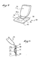
- FIG. 7 and 8 is illustrated a second embodiment of a backpack according to the invention.
- This second embodiment only differs from the first embodiment by the presence of a comfort pad 80 which is glued on the outer surface of the back side 20 of the pack, and by the presence of a hip-belt 36 which is connected to the back side 20 of the pack portion by a disconnectable pivoting connection mechanism 82 which is very schematically depicted.
- the pivoting connection mechanism 82 has a socket 84 which is affixed to the back side 20 of the pack portion, in a lumber part thereof.
- the socket 84 another exemplary embodiment of which is shown on Figures 9 and 11 , can be affixed by any known technique, but it will be most advantageously be affixed by adhesive bonding, e.g. by gluing.
- the socket has a base 85, the size of which can be adjusted to provide enough adhesion surface, and an annular rim 86 with a number of internal radial grooves 87 (only two on Figure 7 , but four on Figures 9 and 11 ). Each radial groove 87 extends around a certain angle.
- the rim 86 has a corresponding number of notches 88, each at one extremity of the corresponding groove 87.
- the pivoting connection mechanism 82 has, affixed to the hip-belt 36, a cylindrical fitting 90 (adapted to be axially fitted within the annular rim 86 so as to form a pivoting connection) with radial studs 92.
- a fitting 90 is shown on Figures 9 and 11 .
- the studs 92 correspond in shape and in number to the notches 88 of the rim 86, so that they can be introduced axially through the notches 88, and, by a proper rotation, be inserted in the radial grooves 87 of the socket 84 to prevent the axial release of the fitting 90 from the socket 84, while allowing a rotation of the fitting relative to the socket.
- the fitting 90 also has a base 94 by which it can be affixed to the cushioned hip-belt 36, for example by gluing.
- the base parts 85, 94 of the socket 84 and of the fitting 90 will preferably have an outer peripheral flange 89, 99 which is flexible.
- the flexible flange 89, 99 of both parts will be integral with the base, each connection part being preferably moulded in one piece from plastic material. In such a case, the outer flanges will be made sufficiently thin to be flexible, while the rest of the part is substantially rigid.
- the flange will preferably be a mere extension of the base part so that they exhibit a single flush back surface, adapted to lie against the corresponding element of the pack.
- the flexible flange portion 89, 99 of the parts will be very important if those parts are assembled by adhesive bonding because they will prevent or at least reduce the risk of peeling off.
- pivoting connections could be used, and the skilled man in the art would easily figure out a convenient embodiment.
- More complex connecting mechanisms could also be used to link the hip belt to the pack, for example mechanisms with dual pivoting rods.
- the socket and the fitting could have interchanged positions on the hip-belt and on the pack.
- the above cushioned hip-belt 36 and its pivoting connection mechanism 82 is particularly relevant in the context of the invention where the back side 20 of the pack, and particularly its lumber part, is reinforced by an adhesively bonded frame 42. Indeed, the presence of the frame 42 in the lumbar part of the pack, where the hip-belt 36 is also connected the pack, will permit a very stable and precise fixing of the pivot mechanism 82. If the latter is also adhesively bonded to the pack, there will be no parasitic lateral or vertical movement between the hip-belt, the frame 42, and the shoulder straps 26, achieving superior carrying ability.
- the hip-belt 36 can also be perfectly positioned and tightened around the hips of the user, while the pivot mechanism 82 will provide the adequate freedom of movement between the shoulder straps 26 and the hip-belt 36 for the pack to follow the movements of the user's back.
- the frame is adhesively bonded to the inner surface of the back side of the pack. Nevertheless, it is also within the scope of the invention to provide that the frame be adhesively bonded to the outer surface. In such a case, it will be interesting from a manufacturing standpoint to have at least part of the carrying system (and of other accessories) affixed to the frame instead of having them directly affixed to the pack.
Claims (21)
- Ein Rucksack mit:einem Packabschnitt (12) aus flexiblem Material, welcher eine hintere Seite (20) einschließt,ein Tragesystem, welches direkt oder indirekt mit dem Packabschnitt verbunden ist, und zumindest einen Schultergurt (26) umfasst, der durch ein oberes Ende (28a) mit einem oberen Schultergurtbefestigungsabschnitt der hinteren Seite des Packabschnitts (12) verbunden ist,einen Rahmen, welcher mit dem Packabschnitt verbunden ist,wobei der Rahmen zumindest einen starren oder halbstarren Blattrahmen (42) umfasst, welcher an der hinteren Seite (20) des Packabschnitts (12) durch Verkleben befestigt ist, und wobei sich der Blattrahmen (42) entlang eines Bereichs der hinteren Seite (20) erstreckt, und der Bereich einen Lendenabschnitt auf der hinteren Seite einschließt, und das obere Ende (28a) des Schultergurts (26) mit dem entsprechenden Schultergurtbefestigungsabschnitt verbunden ist,dadurch gekennzeichnet, dass der Bereich der hinteren Seite zumindest einen oberen Schultergurtbefestigungsabschnitt einschließt, und dadurch dass das obere Ende (28a) des Schultergurts (26) mit dem entsprechenden Schultergurtbefestigungsabschnitt durch Aufkleben verbunden ist.
- Rucksack nach Anspruch 1, dadurch gekennzeichnet, dass das zumindest eine tragende Element ein Paar Schultergurte (26) und einen Hüftgurt (36) umfasst, wobei jeder Schultergurt durch ein oberes Ende (28a) und ein unteres Ende (30a) jeweils mit den oberen und unteren Schultergurtbefestigungsabschnitten der hinteren Seite (20) verbunden ist, und der Hüftgurt (36) mit zumindest einem Hüftgurtbefestigungsabschnitt auf der hinteren Seite befestigt ist, und wobei der Blattrahmen (42) sich entlang eines Bereichs auf der hinteren Seite erstreckt, welcher zumindest die oberen Schultergurtbefestigungsabschnitte und den Hüftgurtbefestigungsabschnitt der hinteren Seite einschließt.
- Rucksack nach Anspruch 2, dadurch gekennzeichnet, dass der Hüftgurt (36) durch Verkleben mit dem Packabschnitt (12) verbunden ist.
- Rucksack nach irgendeinem der vorherigen Ansprüche, dadurch gekennzeichnet, dass der Blattrahmen (42) mit einer inneren Oberfläche der hinteren Seite (20) des Packabschnitts verklebt ist.
- Rucksack nach irgendeinem der vorherigen Ansprüche 1 bis 3, wobei der Blattrahmen (42) mit einer äußeren Oberfläche der hinteren Seite verklebt ist, so dass das Tragesystem indirekt mit dem Packabschnitt über den Blattrahmen verbunden ist.
- Rucksack nach irgendeinem der vorherigen Ansprüche, dadurch gekennzeichnet, dass der Blattrahmen (42) im Wesentlichen gleichmäßig entlang eines wesentlichen Teils der Oberfläche, welche mit der hinteren Seite (20) des Packabschnitts in Kontakt steht, verbunden ist.
- Rucksack nach irgendeinem der vorherigen Ansprüche, dadurch gekennzeichnet, dass der Blattrahmen (42) mit der hinteren Seite (20) unter Verwendung einer thermisch aktivierten Bindeschicht verbunden ist.
- Rucksack nach irgendeinem der vorherigen Ansprüche, dadurch gekennzeichnet, dass der Blattrahmen (42) mit der hinteren Seite (20) unter Verwendung eines Klebeverbundes verbunden ist, welcher zumindest eine zwischen zwei Flächen liegende Schicht zwischen zwei Haftschichten umfasst.
- Rucksack nach irgendeinem der vorherigen Ansprüche, dadurch gekennzeichnet, dass der Blattrahmen (42) einstückig ist.
- Rucksack nach irgendeinem der Ansprüche 1 bis 8, dadurch gekennzeichnet, dass der Blattrahmen in zumindest zwei Blattrahmenelemente unterteilt ist, welche jeweils mit der hinteren Seite des hinteren Abschnitts verbunden sind.
- Rucksack nach Anspruch 10, wobei die Blattrahmenelemente durch eine starre Struktur miteinander verbunden sind.
- Rucksack nach irgendeinem der vorherigen Ansprüche, dadurch gekennzeichnet, dass der Blattrahmen (42) ein Blatt aus Kunststoff (46) einschließt.
- Rucksack nach irgendeinem der vorherigen Ansprüche, wobei der Blattrahmen (42) ein Blatt aus einem elastisch verformbaren Schaum (48) einschließt.
- Rucksack nach irgendeinem der vorherigen Ansprüche, dadurch gekennzeichnet, dass der Blattrahmen (42) ein Blatt aus Kunststoff (46) einschließt, welches an ein Blatt aus elastisch verformbaren Schaum (48) geklebt ist.
- Rucksack nach irgendeinem der vorherigen Ansprüche, dadurch gekennzeichnet, dass der Blattrahmen (42) durch zumindest eine starre Stange (52) verstärkt ist.
- Rucksack nach irgendeinem der vorherigen Ansprüche, dadurch gekennzeichnet, dass der Packabschnitt (12) aus flexiblem, wasserfesten Material hergestellt ist.
- Rucksack nach irgendeinem der vorherigen Ansprüche, dadurch gekennzeichnet, dass der Packabschnitt aus einem flexiblem, wasserfesten Material hergestellt ist, welches eine äußere Polyuretanbeschichtung aufweist, welche einen Schälwiderstand von zumindest 10 Pfund pro Inch nach dem Federal Test Method Standard 191A/5970 aufweist.
- Rucksack nach irgendeinem der vorherigen Ansprüche und mit einem Hüftgurt, dadurch gekennzeichnet, dass der Hüftgurt mit dem Packabschnitt durch einen Drehverbindungsmechanismus (84, 90) verbunden ist.
- Rucksack nach Anspruch 18, dadurch gekennzeichnet, dass der drehbare Verbindungsmechanismus zumindest ein drehbares Teil (84, 90) umfasst, welches an der hinteren Seite (20) des Packabschnitts durch Verkleben befestigt ist.
- Rucksack nach Anspruch 19, dadurch gekennzeichnet, dass das Drehteil (84, 90), welches an der hinteren Seite (20) des Packabschnitts befestigt ist, einen Basisteil (85, 94) mit einem peripheren äußeren flexiblen Flansch (89, 99) umfasst.
- Rucksack nach Anspruch 20, dadurch gekennzeichnet, dass die flexiblen Flansche (89, 99) einstückig mit dem Basisteil (85, 94) des Drehteils (84, 90) gebildet sind.
Priority Applications (6)
| Application Number | Priority Date | Filing Date | Title |
|---|---|---|---|
| DE602005006257T DE602005006257T2 (de) | 2005-06-20 | 2005-06-20 | Verbesserter Rucksack |
| AT05013246T ATE392830T1 (de) | 2005-06-20 | 2005-06-20 | Verbesserter rucksack |
| EP05013246A EP1736074B1 (de) | 2005-06-20 | 2005-06-20 | Verbesserter Rucksack |
| US11/205,076 US8893940B2 (en) | 2005-06-20 | 2005-08-17 | Bag or pack, such as a backpack |
| CN200610084771.9A CN1883333B (zh) | 2005-06-20 | 2006-05-17 | 包和背包 |
| NO20062899A NO20062899L (no) | 2005-06-20 | 2006-06-20 | Bag eller sekk, slik som ryggsekk |
Applications Claiming Priority (1)
| Application Number | Priority Date | Filing Date | Title |
|---|---|---|---|
| EP05013246A EP1736074B1 (de) | 2005-06-20 | 2005-06-20 | Verbesserter Rucksack |
Publications (2)
| Publication Number | Publication Date |
|---|---|
| EP1736074A1 EP1736074A1 (de) | 2006-12-27 |
| EP1736074B1 true EP1736074B1 (de) | 2008-04-23 |
Family
ID=35311501
Family Applications (1)
| Application Number | Title | Priority Date | Filing Date |
|---|---|---|---|
| EP05013246A Active EP1736074B1 (de) | 2005-06-20 | 2005-06-20 | Verbesserter Rucksack |
Country Status (6)
| Country | Link |
|---|---|
| US (1) | US8893940B2 (de) |
| EP (1) | EP1736074B1 (de) |
| CN (1) | CN1883333B (de) |
| AT (1) | ATE392830T1 (de) |
| DE (1) | DE602005006257T2 (de) |
| NO (1) | NO20062899L (de) |
Families Citing this family (49)
| Publication number | Priority date | Publication date | Assignee | Title |
|---|---|---|---|---|
| US8844781B2 (en) * | 2006-07-19 | 2014-09-30 | Arc'teryx Equipment Inc. | Adjustable positioning mechanism and a bag or pack, such as a backpack or other article, having such mechanism |
| US20090020579A1 (en) * | 2007-07-17 | 2009-01-22 | Arc'teryx Equipment Inc. | Roll-top closure pack |
| US20090179057A1 (en) * | 2008-01-12 | 2009-07-16 | Basye Cathy M | Posture supporting backpack |
| EP2172126A1 (de) * | 2008-10-01 | 2010-04-07 | Nederlandse Organisatie voor toegepast-natuurwetenschappelijk Onderzoek TNO | Rucksack-System |
| WO2010130025A1 (en) | 2009-05-15 | 2010-11-18 | Fyi Design Dept. Ltd. | Methods and apparatus for affixing hardware to garments |
| GB2473233A (en) * | 2009-09-04 | 2011-03-09 | Mmlcs Ltd | Balanced rucksack |
| US20110233084A1 (en) | 2010-01-13 | 2011-09-29 | Watson Christopher M | Storage System for Archery Equipment and Accessories |
| US9636875B2 (en) | 2010-07-16 | 2017-05-02 | Kuiu, Inc. | Methods for making a composite backpack frame |
| US9095203B2 (en) | 2010-07-16 | 2015-08-04 | Kuiu, Inc. | Unitary composite backpack frame with upper stays |
| WO2012009680A2 (en) | 2010-07-16 | 2012-01-19 | Kuiu, Inc. | Backpack frame |
| US8876568B2 (en) * | 2010-09-14 | 2014-11-04 | Arc'teryx Equipment Inc. | Airbag rescue system |
| WO2012061806A1 (en) * | 2010-11-05 | 2012-05-10 | Ehmke Manufacturing | Quick-release weight distribution and connection system |
| US8382618B2 (en) * | 2010-11-22 | 2013-02-26 | Chuan-Hsin Lo | Protective cover for an inflatable ball body, and sports ball having the same |
| US20130099028A1 (en) * | 2011-10-19 | 2013-04-25 | Earthway Products Inc. | Bag rigidizer |
| US9538820B2 (en) * | 2012-07-11 | 2017-01-10 | Karsten Manufacturing Corporation | Strap assembly for bags and methods to manufacture bags having a strap assembly |
| CN103169243B (zh) * | 2013-03-12 | 2015-12-02 | 北京航空航天大学 | 一种新型安全带式双肩背包肩带 |
| DE202013002980U1 (de) * | 2013-03-28 | 2014-07-01 | Rimowa Gmbh | Aufbewahrungseinrichtung mit dreidimensionalen Erhöhungen auf der Außenfläche |
| US9614569B2 (en) * | 2013-08-30 | 2017-04-04 | Wimo Labs LLC | Waterproof casing with exposed display surface |
| US10781028B2 (en) | 2014-02-07 | 2020-09-22 | Yeti Coolers, Llc | Insulating device backpack |
| WO2017136754A1 (en) | 2016-02-05 | 2017-08-10 | Yeti Coolers, Llc | Insulating device |
| US9139352B2 (en) | 2014-02-07 | 2015-09-22 | Yeti Coolers, Llc | Insulating container |
| US10384855B2 (en) | 2014-02-07 | 2019-08-20 | Yeti Coolers, Llc | Insulating device and method for forming insulating device |
| USD934636S1 (en) | 2014-09-08 | 2021-11-02 | Yeti Coolers, Llc | Insulating device |
| USD948954S1 (en) | 2014-09-08 | 2022-04-19 | Yeti Coolers, Llc | Insulating device |
| USD787187S1 (en) | 2014-09-23 | 2017-05-23 | Yeti Coolers, Llc | Insulating device |
| CN114224052B (zh) | 2015-11-02 | 2024-02-06 | 野醍冷却器有限责任公司 | 封闭系统和容器 |
| USD802373S1 (en) | 2016-02-05 | 2017-11-14 | Yeti Coolers, Llc | Insulating device |
| USD801123S1 (en) | 2016-02-05 | 2017-10-31 | Yeti Coolers, Llc | Insulating device |
| US9609938B1 (en) | 2016-02-11 | 2017-04-04 | Timbuk 2 Designs, Inc. | Waterproof backpacks and carrying bags |
| USD805851S1 (en) | 2016-06-01 | 2017-12-26 | Yeti Coolers, Llc | Cooler |
| USD808730S1 (en) | 2016-06-01 | 2018-01-30 | Yeti Coolers, Llc | Cooler |
| USD829244S1 (en) | 2017-04-25 | 2018-09-25 | Yeti Coolers, Llc | Insulating device |
| AU2018279644B2 (en) | 2017-06-09 | 2024-02-01 | Yeti Coolers, Llc | Insulating device |
| US10165846B1 (en) | 2017-06-16 | 2019-01-01 | Camelbak Products, Llc | Backpacks with cooperatively adjusted hip belts and compression straps |
| FR3070195B1 (fr) | 2017-08-20 | 2019-09-20 | Emmanuel Brun | Dispositif de fixation |
| WO2019038243A1 (fr) * | 2017-08-20 | 2019-02-28 | Brun Emmanuel | Dispositif de fixation |
| WO2019071225A1 (en) | 2017-10-05 | 2019-04-11 | Dakine, Inc. | ENCLOSURE OF INFLATABLE SAFETY CUSHION COMPARTMENT |
| USD848219S1 (en) | 2017-10-30 | 2019-05-14 | Yeti Coolers, Llc | Backpack cooler |
| EP3727075A1 (de) * | 2017-12-18 | 2020-10-28 | Yeti Coolers, LLC | Rucksack mit isoliervorrichtung |
| US11723831B2 (en) * | 2019-04-16 | 2023-08-15 | Li Zhijian | Adjustable massage structure and massage backpack |
| US11612232B1 (en) * | 2019-11-08 | 2023-03-28 | Vamose Llc | Attachable sports bag for use alone or in conjunction with another backpack |
| USD929192S1 (en) | 2019-11-15 | 2021-08-31 | Yeti Coolers, Llc | Insulating device |
| USD929191S1 (en) | 2019-11-15 | 2021-08-31 | Yeti Coolers, Llc | Insulating device |
| US11242189B2 (en) | 2019-11-15 | 2022-02-08 | Yeti Coolers, Llc | Insulating device |
| CA3174671A1 (en) | 2020-04-09 | 2021-10-14 | GAF Energy LLC | Three-dimensional laminate photovoltaic module |
| US11110307B1 (en) * | 2020-04-20 | 2021-09-07 | Kathiana Possible | Gas tank storage bag |
| USD960560S1 (en) * | 2021-04-21 | 2022-08-16 | Xiamen Worthfind E-Commerce Co., Ltd. | Insulated backpack |
| USD960561S1 (en) * | 2021-04-23 | 2022-08-16 | Xiamen Worthfind E-Commerce Co., Ltd. | Insulated backpack |
| US11758999B1 (en) * | 2022-03-07 | 2023-09-19 | Amer Sports Canada Inc. | Pack |
Family Cites Families (48)
| Publication number | Priority date | Publication date | Assignee | Title |
|---|---|---|---|---|
| US3347429A (en) * | 1966-11-07 | 1967-10-17 | Jr Harold Stuart Ruth | Contour shoulder pack |
| US3767040A (en) * | 1971-03-01 | 1973-10-23 | Minnesota Mining & Mfg | Pressure-sensitive polyurethane adhesives |
| US3957184A (en) * | 1974-08-19 | 1976-05-18 | Shurman Daniel A | Back pack with resilient bands for spacing the pack from the wearer |
| AT338453B (de) * | 1975-03-19 | 1977-08-25 | Arno Grunberger | Schultasche |
| US4074839A (en) * | 1976-05-10 | 1978-02-21 | Wood Thomas E | Internal frame backpack |
| US4080677A (en) * | 1977-02-11 | 1978-03-28 | Koehler Carlton L | Portable diver distress signalling device |
| DE2754061A1 (de) * | 1977-12-05 | 1979-06-13 | Knut Jaeger | Auf dem ruecken tragbares behaeltnis mit traggestell |
| US4213549A (en) * | 1979-06-18 | 1980-07-22 | Phoenix Products, Inc. | Waterproof storage bag and backpack |
| US4489770A (en) * | 1983-04-11 | 1984-12-25 | Egon Reich | Waterproof enclosure |
| CA1247568A (en) | 1984-01-13 | 1988-12-28 | Greg E. Lowe | Method and structure for attaching adjustable backpack straps |
| FR2575049B1 (fr) | 1984-12-20 | 1987-03-06 | Millet Sacs | Sac a dos |
| US4653290A (en) * | 1986-06-24 | 1987-03-31 | Byrne Shelley R | Beer keg ice sleeve and method of making same |
| GB8619473D0 (en) | 1986-08-09 | 1986-09-17 | Karrimor Int Ltd | Rucksack frame fastening means |
| EP0257142A1 (de) * | 1986-08-11 | 1988-03-02 | Karrimor International Limited | Rucksack mit mittlerer Öffnung |
| US4920575A (en) * | 1986-10-20 | 1990-05-01 | Bodigard Technologies, Inc. | Protective garment material and construction |
| US4830245A (en) * | 1986-12-15 | 1989-05-16 | Arakaki Steven Y | Backpack carrier and shield |
| US4790463A (en) * | 1987-06-30 | 1988-12-13 | Viking-Stavanger A/S | Diver's bag |
| GB8923455D0 (en) | 1989-10-18 | 1989-12-06 | Karrimor Int Ltd | Rucksack with detachable harness and/or detachable hip pad |
| US5366126A (en) * | 1990-08-10 | 1994-11-22 | Ulrich Dausien | Knapsack with reinforcing element |
| US5131576A (en) * | 1990-09-17 | 1992-07-21 | Kent Turnipseed | Backpack support device |
| US5320262A (en) * | 1992-11-03 | 1994-06-14 | Mountain Equipment, Inc. | Internal frame pack and support device therefor |
| US5361955A (en) * | 1992-12-21 | 1994-11-08 | Bianchi International | Modular backpack |
| US5641325A (en) * | 1993-04-13 | 1997-06-24 | Tecnol, Inc. | Ice pack |
| US5427290A (en) * | 1994-01-10 | 1995-06-27 | Ultimate Direction, Inc. | Water pouch backpack |
| US5954253A (en) * | 1996-06-26 | 1999-09-21 | Johnson Worldwide Associates, Inc. | Flexible frame load carrying system |
| US5890640A (en) * | 1996-08-14 | 1999-04-06 | K-2 Corporation | Internal frame pack with load-responsive spring rods |
| US5902073A (en) * | 1997-01-08 | 1999-05-11 | Johnson Worldwide Associates | Equipment support garment for divers |
| US6029875A (en) * | 1997-06-13 | 2000-02-29 | Johnston; Patrick | Bicycle mounted knapsack |
| FR2778825B1 (fr) | 1998-05-25 | 2000-07-13 | Lafuma Sa | Dispositif de reglage en longueur de moyen de portage et/ou ceinturage pour systemes de portage de charges a dos |
| FR2781135B1 (fr) * | 1998-07-17 | 2000-08-18 | Rossignol Sa | Sac dorsal porte aux deux epaules au moyen d'une paire de bretelles |
| US6055975A (en) * | 1998-07-30 | 2000-05-02 | The Paintball Emporium, Inc. | Paintball container |
| US6279804B1 (en) * | 1998-08-06 | 2001-08-28 | Ron Gregg | Strap attachment system |
| US6073822A (en) * | 1999-01-28 | 2000-06-13 | Aaron Schwartz | Knapsack with rigid, solid member such as a hubcap |
| US6460746B1 (en) * | 1999-04-21 | 2002-10-08 | Fred M. B. Amram | Backpack having removable, re-positionable carrying straps |
| US6626342B1 (en) * | 1999-06-07 | 2003-09-30 | Dana W. Gleason | Backpack having a modular frame |
| US6343729B1 (en) * | 1999-08-31 | 2002-02-05 | Advance Polybag, Inc | Disposable backpack |
| US6325262B1 (en) * | 2000-08-31 | 2001-12-04 | K-2 Corporation | Backpack with ram air channel |
| US6474523B2 (en) * | 2001-01-08 | 2002-11-05 | Trg Accessories Llc | Piece of baggage having an adjustable strap for alternatively supporting the piece of baggage from one's waist or shoulder |
| US6607108B2 (en) * | 2001-02-13 | 2003-08-19 | Recreational Equipment, Inc. | Load transfer and stabilization system for backpacks |
| US6478464B1 (en) * | 2001-07-09 | 2002-11-12 | David S. Miller | Laundry retention device |
| US6871766B2 (en) * | 2002-02-28 | 2005-03-29 | Trg Accessories, L.L.C. | Pivoting shoulder strap for a backpack |
| ATE476168T1 (de) * | 2002-11-27 | 2010-08-15 | Kappler Inc | Transportierbarer sack für kontaminierte überreste |
| US7455743B2 (en) * | 2003-05-21 | 2008-11-25 | Mountain Hardwear, Inc. | Adhesively bonded seams and methods of forming seams |
| US20050035170A1 (en) * | 2003-08-12 | 2005-02-17 | Bianchi International | Backpack having framesheet assembly |
| US7210605B2 (en) * | 2003-08-30 | 2007-05-01 | Willows Keith S | Harness |
| US20060072857A1 (en) * | 2004-10-04 | 2006-04-06 | Eric Revels | Waterproof carrying bag |
| DE202004016070U1 (de) * | 2004-10-16 | 2005-01-20 | Mühlberger GmbH | Rucksack mit Luftpolsterung im Rückenteil zum Ausklappen als Sitzkissen |
| US20060218691A1 (en) * | 2005-03-29 | 2006-10-05 | Samuel Miller | Amphibious self-bailing backpack |
-
2005
- 2005-06-20 EP EP05013246A patent/EP1736074B1/de active Active
- 2005-06-20 AT AT05013246T patent/ATE392830T1/de not_active IP Right Cessation
- 2005-06-20 DE DE602005006257T patent/DE602005006257T2/de active Active
- 2005-08-17 US US11/205,076 patent/US8893940B2/en active Active
-
2006
- 2006-05-17 CN CN200610084771.9A patent/CN1883333B/zh active Active
- 2006-06-20 NO NO20062899A patent/NO20062899L/no unknown
Also Published As
| Publication number | Publication date |
|---|---|
| EP1736074A1 (de) | 2006-12-27 |
| DE602005006257D1 (de) | 2008-06-05 |
| ATE392830T1 (de) | 2008-05-15 |
| NO20062899L (no) | 2006-12-21 |
| DE602005006257T2 (de) | 2009-06-25 |
| US20060283907A1 (en) | 2006-12-21 |
| US8893940B2 (en) | 2014-11-25 |
| CN1883333A (zh) | 2006-12-27 |
| CN1883333B (zh) | 2010-08-18 |
Similar Documents
| Publication | Publication Date | Title |
|---|---|---|
| EP1736074B1 (de) | Verbesserter Rucksack | |
| US8844781B2 (en) | Adjustable positioning mechanism and a bag or pack, such as a backpack or other article, having such mechanism | |
| US6626342B1 (en) | Backpack having a modular frame | |
| US8123581B2 (en) | Avalanche rescue device | |
| US4921151A (en) | Bicycle rear carrier pack | |
| US4469256A (en) | Cover apparatus with detachable compartments | |
| US4949401A (en) | Collapsible multicompartmented pack for the back of a garment | |
| US4375828A (en) | Portable insulated container | |
| US5836489A (en) | Belt assembly for a load carrying system | |
| TWI586594B (zh) | 保護性邊緣插入件,包含該插入件的箱子,及製造與使用的方法 | |
| US20130243354A1 (en) | Self sealing waterproof bag | |
| US20050189388A1 (en) | Framed soft sided carrier for tools | |
| US9113696B2 (en) | Backpack shoulder strap | |
| US11547200B2 (en) | Backpack system with waterproof bag | |
| JPS61247409A (ja) | リユツクザツク | |
| US9480325B2 (en) | Backpack that converts to a sleeping mat | |
| CA2849440A1 (en) | Body armor support harness | |
| US20110200395A1 (en) | Method of manufacturing a buoyancy control device | |
| US20070000964A1 (en) | Accessory for detachably connecting a web-belt to a backpack or the like | |
| US20190191856A1 (en) | Backpack having a vertical holding frame and a support cover | |
| KR20040106204A (ko) | 배낭 | |
| US6755288B1 (en) | Luggage structure | |
| CA2239921A1 (en) | Convertible backpack | |
| JP2023061506A (ja) | ランドセル | |
| JP2532796Y2 (ja) | ファルトボートの収納バッグ |
Legal Events
| Date | Code | Title | Description |
|---|---|---|---|
| PUAI | Public reference made under article 153(3) epc to a published international application that has entered the european phase |
Free format text: ORIGINAL CODE: 0009012 |
|
| 17P | Request for examination filed |
Effective date: 20050620 |
|
| AK | Designated contracting states |
Kind code of ref document: A1 Designated state(s): AT BE BG CH CY CZ DE DK EE ES FI FR GB GR HU IE IS IT LI LT LU MC NL PL PT RO SE SI SK TR |
|
| AX | Request for extension of the european patent |
Extension state: AL BA HR LV MK YU |
|
| AKX | Designation fees paid |
Designated state(s): AT BE BG CH CY CZ DE DK EE ES FI FR GB GR HU IE IS IT LI LT LU MC NL PL PT RO SE SI SK TR |
|
| GRAP | Despatch of communication of intention to grant a patent |
Free format text: ORIGINAL CODE: EPIDOSNIGR1 |
|
| GRAS | Grant fee paid |
Free format text: ORIGINAL CODE: EPIDOSNIGR3 |
|
| GRAA | (expected) grant |
Free format text: ORIGINAL CODE: 0009210 |
|
| AK | Designated contracting states |
Kind code of ref document: B1 Designated state(s): AT BE BG CH CY CZ DE DK EE ES FI FR GB GR HU IE IS IT LI LT LU MC NL PL PT RO SE SI SK TR |
|
| REG | Reference to a national code |
Ref country code: GB Ref legal event code: FG4D |
|
| REG | Reference to a national code |
Ref country code: CH Ref legal event code: EP |
|
| REF | Corresponds to: |
Ref document number: 602005006257 Country of ref document: DE Date of ref document: 20080605 Kind code of ref document: P |
|
| REG | Reference to a national code |
Ref country code: IE Ref legal event code: FG4D Free format text: LANGUAGE OF EP DOCUMENT: FRENCH |
|
| PG25 | Lapsed in a contracting state [announced via postgrant information from national office to epo] |
Ref country code: SI Free format text: LAPSE BECAUSE OF FAILURE TO SUBMIT A TRANSLATION OF THE DESCRIPTION OR TO PAY THE FEE WITHIN THE PRESCRIBED TIME-LIMIT Effective date: 20080423 |
|
| NLV1 | Nl: lapsed or annulled due to failure to fulfill the requirements of art. 29p and 29m of the patents act | ||
| PG25 | Lapsed in a contracting state [announced via postgrant information from national office to epo] |
Ref country code: ES Free format text: LAPSE BECAUSE OF FAILURE TO SUBMIT A TRANSLATION OF THE DESCRIPTION OR TO PAY THE FEE WITHIN THE PRESCRIBED TIME-LIMIT Effective date: 20080803 Ref country code: NL Free format text: LAPSE BECAUSE OF FAILURE TO SUBMIT A TRANSLATION OF THE DESCRIPTION OR TO PAY THE FEE WITHIN THE PRESCRIBED TIME-LIMIT Effective date: 20080423 Ref country code: BG Free format text: LAPSE BECAUSE OF FAILURE TO SUBMIT A TRANSLATION OF THE DESCRIPTION OR TO PAY THE FEE WITHIN THE PRESCRIBED TIME-LIMIT Effective date: 20080723 Ref country code: PT Free format text: LAPSE BECAUSE OF FAILURE TO SUBMIT A TRANSLATION OF THE DESCRIPTION OR TO PAY THE FEE WITHIN THE PRESCRIBED TIME-LIMIT Effective date: 20080923 Ref country code: FI Free format text: LAPSE BECAUSE OF FAILURE TO SUBMIT A TRANSLATION OF THE DESCRIPTION OR TO PAY THE FEE WITHIN THE PRESCRIBED TIME-LIMIT Effective date: 20080423 |
|
| PG25 | Lapsed in a contracting state [announced via postgrant information from national office to epo] |
Ref country code: AT Free format text: LAPSE BECAUSE OF FAILURE TO SUBMIT A TRANSLATION OF THE DESCRIPTION OR TO PAY THE FEE WITHIN THE PRESCRIBED TIME-LIMIT Effective date: 20080423 Ref country code: PL Free format text: LAPSE BECAUSE OF FAILURE TO SUBMIT A TRANSLATION OF THE DESCRIPTION OR TO PAY THE FEE WITHIN THE PRESCRIBED TIME-LIMIT Effective date: 20080423 |
|
| PGFP | Annual fee paid to national office [announced via postgrant information from national office to epo] |
Ref country code: FR Payment date: 20080625 Year of fee payment: 4 |
|
| PG25 | Lapsed in a contracting state [announced via postgrant information from national office to epo] |
Ref country code: IS Free format text: LAPSE BECAUSE OF FAILURE TO SUBMIT A TRANSLATION OF THE DESCRIPTION OR TO PAY THE FEE WITHIN THE PRESCRIBED TIME-LIMIT Effective date: 20080823 |
|
| PG25 | Lapsed in a contracting state [announced via postgrant information from national office to epo] |
Ref country code: LT Free format text: LAPSE BECAUSE OF FAILURE TO SUBMIT A TRANSLATION OF THE DESCRIPTION OR TO PAY THE FEE WITHIN THE PRESCRIBED TIME-LIMIT Effective date: 20080423 Ref country code: SE Free format text: LAPSE BECAUSE OF FAILURE TO SUBMIT A TRANSLATION OF THE DESCRIPTION OR TO PAY THE FEE WITHIN THE PRESCRIBED TIME-LIMIT Effective date: 20080723 Ref country code: MC Free format text: LAPSE BECAUSE OF NON-PAYMENT OF DUE FEES Effective date: 20080630 Ref country code: CZ Free format text: LAPSE BECAUSE OF FAILURE TO SUBMIT A TRANSLATION OF THE DESCRIPTION OR TO PAY THE FEE WITHIN THE PRESCRIBED TIME-LIMIT Effective date: 20080423 Ref country code: DK Free format text: LAPSE BECAUSE OF FAILURE TO SUBMIT A TRANSLATION OF THE DESCRIPTION OR TO PAY THE FEE WITHIN THE PRESCRIBED TIME-LIMIT Effective date: 20080423 |
|
| EN | Fr: translation not filed | ||
| PG25 | Lapsed in a contracting state [announced via postgrant information from national office to epo] |
Ref country code: SK Free format text: LAPSE BECAUSE OF FAILURE TO SUBMIT A TRANSLATION OF THE DESCRIPTION OR TO PAY THE FEE WITHIN THE PRESCRIBED TIME-LIMIT Effective date: 20080423 Ref country code: RO Free format text: LAPSE BECAUSE OF FAILURE TO SUBMIT A TRANSLATION OF THE DESCRIPTION OR TO PAY THE FEE WITHIN THE PRESCRIBED TIME-LIMIT Effective date: 20080423 Ref country code: BE Free format text: LAPSE BECAUSE OF FAILURE TO SUBMIT A TRANSLATION OF THE DESCRIPTION OR TO PAY THE FEE WITHIN THE PRESCRIBED TIME-LIMIT Effective date: 20080423 |
|
| PLBE | No opposition filed within time limit |
Free format text: ORIGINAL CODE: 0009261 |
|
| STAA | Information on the status of an ep patent application or granted ep patent |
Free format text: STATUS: NO OPPOSITION FILED WITHIN TIME LIMIT |
|
| 26N | No opposition filed |
Effective date: 20090126 |
|
| REG | Reference to a national code |
Ref country code: IE Ref legal event code: MM4A |
|
| PG25 | Lapsed in a contracting state [announced via postgrant information from national office to epo] |
Ref country code: IE Free format text: LAPSE BECAUSE OF NON-PAYMENT OF DUE FEES Effective date: 20080620 Ref country code: EE Free format text: LAPSE BECAUSE OF FAILURE TO SUBMIT A TRANSLATION OF THE DESCRIPTION OR TO PAY THE FEE WITHIN THE PRESCRIBED TIME-LIMIT Effective date: 20080423 Ref country code: FR Free format text: LAPSE BECAUSE OF FAILURE TO SUBMIT A TRANSLATION OF THE DESCRIPTION OR TO PAY THE FEE WITHIN THE PRESCRIBED TIME-LIMIT Effective date: 20090227 |
|
| PG25 | Lapsed in a contracting state [announced via postgrant information from national office to epo] |
Ref country code: IT Free format text: LAPSE BECAUSE OF FAILURE TO SUBMIT A TRANSLATION OF THE DESCRIPTION OR TO PAY THE FEE WITHIN THE PRESCRIBED TIME-LIMIT Effective date: 20080423 |
|
| PG25 | Lapsed in a contracting state [announced via postgrant information from national office to epo] |
Ref country code: CY Free format text: LAPSE BECAUSE OF FAILURE TO SUBMIT A TRANSLATION OF THE DESCRIPTION OR TO PAY THE FEE WITHIN THE PRESCRIBED TIME-LIMIT Effective date: 20080423 Ref country code: HU Free format text: LAPSE BECAUSE OF FAILURE TO SUBMIT A TRANSLATION OF THE DESCRIPTION OR TO PAY THE FEE WITHIN THE PRESCRIBED TIME-LIMIT Effective date: 20081024 Ref country code: LU Free format text: LAPSE BECAUSE OF NON-PAYMENT OF DUE FEES Effective date: 20080620 |
|
| PG25 | Lapsed in a contracting state [announced via postgrant information from national office to epo] |
Ref country code: TR Free format text: LAPSE BECAUSE OF FAILURE TO SUBMIT A TRANSLATION OF THE DESCRIPTION OR TO PAY THE FEE WITHIN THE PRESCRIBED TIME-LIMIT Effective date: 20080423 |
|
| PG25 | Lapsed in a contracting state [announced via postgrant information from national office to epo] |
Ref country code: GR Free format text: LAPSE BECAUSE OF FAILURE TO SUBMIT A TRANSLATION OF THE DESCRIPTION OR TO PAY THE FEE WITHIN THE PRESCRIBED TIME-LIMIT Effective date: 20080724 |
|
| PGFP | Annual fee paid to national office [announced via postgrant information from national office to epo] |
Ref country code: DE Payment date: 20230502 Year of fee payment: 19 |
|
| PGFP | Annual fee paid to national office [announced via postgrant information from national office to epo] |
Ref country code: GB Payment date: 20230504 Year of fee payment: 19 Ref country code: CH Payment date: 20230702 Year of fee payment: 19 |