EP1735767B1 - Procédé et dispositif pour améliorer la conformité d'un panneau d' affichage avec un standard d'affichage dans toute la surface d'affichage et pour différents angles visuels - Google Patents
Procédé et dispositif pour améliorer la conformité d'un panneau d' affichage avec un standard d'affichage dans toute la surface d'affichage et pour différents angles visuels Download PDFInfo
- Publication number
- EP1735767B1 EP1735767B1 EP05779896.9A EP05779896A EP1735767B1 EP 1735767 B1 EP1735767 B1 EP 1735767B1 EP 05779896 A EP05779896 A EP 05779896A EP 1735767 B1 EP1735767 B1 EP 1735767B1
- Authority
- EP
- European Patent Office
- Prior art keywords
- display
- colour
- greyscale
- correcting
- zone
- Prior art date
- Legal status (The legal status is an assumption and is not a legal conclusion. Google has not performed a legal analysis and makes no representation as to the accuracy of the status listed.)
- Active
Links
- 238000000034 method Methods 0.000 title claims description 111
- 238000012937 correction Methods 0.000 claims description 78
- 230000006870 function Effects 0.000 claims description 63
- 238000012512 characterization method Methods 0.000 claims description 54
- 239000011159 matrix material Substances 0.000 claims description 44
- 230000007613 environmental effect Effects 0.000 claims description 13
- 238000001514 detection method Methods 0.000 claims description 9
- 238000003384 imaging method Methods 0.000 claims description 9
- 238000004891 communication Methods 0.000 claims description 8
- 229940079593 drug Drugs 0.000 claims description 5
- 239000003814 drug Substances 0.000 claims description 5
- 238000007620 mathematical function Methods 0.000 claims description 5
- 238000012546 transfer Methods 0.000 description 57
- 230000006399 behavior Effects 0.000 description 52
- 238000005259 measurement Methods 0.000 description 38
- 238000011088 calibration curve Methods 0.000 description 22
- 239000013589 supplement Substances 0.000 description 9
- 239000013598 vector Substances 0.000 description 9
- 230000008901 benefit Effects 0.000 description 8
- 230000008859 change Effects 0.000 description 8
- 230000007423 decrease Effects 0.000 description 8
- 238000006243 chemical reaction Methods 0.000 description 7
- 230000001419 dependent effect Effects 0.000 description 7
- 238000002059 diagnostic imaging Methods 0.000 description 7
- CYTYCFOTNPOANT-UHFFFAOYSA-N Perchloroethylene Chemical compound ClC(Cl)=C(Cl)Cl CYTYCFOTNPOANT-UHFFFAOYSA-N 0.000 description 5
- 238000010586 diagram Methods 0.000 description 5
- 238000012545 processing Methods 0.000 description 5
- 230000006872 improvement Effects 0.000 description 4
- 238000013459 approach Methods 0.000 description 3
- 238000004422 calculation algorithm Methods 0.000 description 3
- 239000003086 colorant Substances 0.000 description 3
- 238000003745 diagnosis Methods 0.000 description 3
- 230000000694 effects Effects 0.000 description 3
- 238000004519 manufacturing process Methods 0.000 description 3
- 238000000275 quality assurance Methods 0.000 description 3
- 230000000007 visual effect Effects 0.000 description 3
- 241001465754 Metazoa Species 0.000 description 2
- 230000006978 adaptation Effects 0.000 description 2
- 230000005540 biological transmission Effects 0.000 description 2
- 238000004364 calculation method Methods 0.000 description 2
- 230000003247 decreasing effect Effects 0.000 description 2
- 238000005516 engineering process Methods 0.000 description 2
- 238000007667 floating Methods 0.000 description 2
- 230000003287 optical effect Effects 0.000 description 2
- 230000004044 response Effects 0.000 description 2
- 230000036962 time dependent Effects 0.000 description 2
- 230000009466 transformation Effects 0.000 description 2
- 238000002604 ultrasonography Methods 0.000 description 2
- 241000282412 Homo Species 0.000 description 1
- 230000032683 aging Effects 0.000 description 1
- 238000010420 art technique Methods 0.000 description 1
- 238000013528 artificial neural network Methods 0.000 description 1
- 230000033228 biological regulation Effects 0.000 description 1
- 230000004456 color vision Effects 0.000 description 1
- 238000004737 colorimetric analysis Methods 0.000 description 1
- 238000012885 constant function Methods 0.000 description 1
- 238000013461 design Methods 0.000 description 1
- 239000000284 extract Substances 0.000 description 1
- 230000002349 favourable effect Effects 0.000 description 1
- 239000011521 glass Substances 0.000 description 1
- 238000010438 heat treatment Methods 0.000 description 1
- 238000010191 image analysis Methods 0.000 description 1
- 238000009434 installation Methods 0.000 description 1
- 230000001788 irregular Effects 0.000 description 1
- 239000004973 liquid crystal related substance Substances 0.000 description 1
- 238000009607 mammography Methods 0.000 description 1
- 238000013507 mapping Methods 0.000 description 1
- 238000003908 quality control method Methods 0.000 description 1
- 238000013139 quantization Methods 0.000 description 1
- 230000035945 sensitivity Effects 0.000 description 1
- 238000012549 training Methods 0.000 description 1
Images


Classifications
-
- G—PHYSICS
- G09—EDUCATION; CRYPTOGRAPHY; DISPLAY; ADVERTISING; SEALS
- G09G—ARRANGEMENTS OR CIRCUITS FOR CONTROL OF INDICATING DEVICES USING STATIC MEANS TO PRESENT VARIABLE INFORMATION
- G09G3/00—Control arrangements or circuits, of interest only in connection with visual indicators other than cathode-ray tubes
- G09G3/20—Control arrangements or circuits, of interest only in connection with visual indicators other than cathode-ray tubes for presentation of an assembly of a number of characters, e.g. a page, by composing the assembly by combination of individual elements arranged in a matrix no fixed position being assigned to or needed to be assigned to the individual characters or partial characters
- G09G3/2092—Details of a display terminals using a flat panel, the details relating to the control arrangement of the display terminal and to the interfaces thereto
-
- G—PHYSICS
- G09—EDUCATION; CRYPTOGRAPHY; DISPLAY; ADVERTISING; SEALS
- G09G—ARRANGEMENTS OR CIRCUITS FOR CONTROL OF INDICATING DEVICES USING STATIC MEANS TO PRESENT VARIABLE INFORMATION
- G09G3/00—Control arrangements or circuits, of interest only in connection with visual indicators other than cathode-ray tubes
- G09G3/20—Control arrangements or circuits, of interest only in connection with visual indicators other than cathode-ray tubes for presentation of an assembly of a number of characters, e.g. a page, by composing the assembly by combination of individual elements arranged in a matrix no fixed position being assigned to or needed to be assigned to the individual characters or partial characters
- G09G3/34—Control arrangements or circuits, of interest only in connection with visual indicators other than cathode-ray tubes for presentation of an assembly of a number of characters, e.g. a page, by composing the assembly by combination of individual elements arranged in a matrix no fixed position being assigned to or needed to be assigned to the individual characters or partial characters by control of light from an independent source
- G09G3/36—Control arrangements or circuits, of interest only in connection with visual indicators other than cathode-ray tubes for presentation of an assembly of a number of characters, e.g. a page, by composing the assembly by combination of individual elements arranged in a matrix no fixed position being assigned to or needed to be assigned to the individual characters or partial characters by control of light from an independent source using liquid crystals
-
- G—PHYSICS
- G09—EDUCATION; CRYPTOGRAPHY; DISPLAY; ADVERTISING; SEALS
- G09G—ARRANGEMENTS OR CIRCUITS FOR CONTROL OF INDICATING DEVICES USING STATIC MEANS TO PRESENT VARIABLE INFORMATION
- G09G5/00—Control arrangements or circuits for visual indicators common to cathode-ray tube indicators and other visual indicators
- G09G5/02—Control arrangements or circuits for visual indicators common to cathode-ray tube indicators and other visual indicators characterised by the way in which colour is displayed
-
- G—PHYSICS
- G09—EDUCATION; CRYPTOGRAPHY; DISPLAY; ADVERTISING; SEALS
- G09G—ARRANGEMENTS OR CIRCUITS FOR CONTROL OF INDICATING DEVICES USING STATIC MEANS TO PRESENT VARIABLE INFORMATION
- G09G2320/00—Control of display operating conditions
- G09G2320/02—Improving the quality of display appearance
- G09G2320/0233—Improving the luminance or brightness uniformity across the screen
-
- G—PHYSICS
- G09—EDUCATION; CRYPTOGRAPHY; DISPLAY; ADVERTISING; SEALS
- G09G—ARRANGEMENTS OR CIRCUITS FOR CONTROL OF INDICATING DEVICES USING STATIC MEANS TO PRESENT VARIABLE INFORMATION
- G09G2320/00—Control of display operating conditions
- G09G2320/02—Improving the quality of display appearance
- G09G2320/0271—Adjustment of the gradation levels within the range of the gradation scale, e.g. by redistribution or clipping
- G09G2320/0276—Adjustment of the gradation levels within the range of the gradation scale, e.g. by redistribution or clipping for the purpose of adaptation to the characteristics of a display device, i.e. gamma correction
-
- G—PHYSICS
- G09—EDUCATION; CRYPTOGRAPHY; DISPLAY; ADVERTISING; SEALS
- G09G—ARRANGEMENTS OR CIRCUITS FOR CONTROL OF INDICATING DEVICES USING STATIC MEANS TO PRESENT VARIABLE INFORMATION
- G09G2320/00—Control of display operating conditions
- G09G2320/02—Improving the quality of display appearance
- G09G2320/028—Improving the quality of display appearance by changing the viewing angle properties, e.g. widening the viewing angle, adapting the viewing angle to the view direction
-
- G—PHYSICS
- G09—EDUCATION; CRYPTOGRAPHY; DISPLAY; ADVERTISING; SEALS
- G09G—ARRANGEMENTS OR CIRCUITS FOR CONTROL OF INDICATING DEVICES USING STATIC MEANS TO PRESENT VARIABLE INFORMATION
- G09G2320/00—Control of display operating conditions
- G09G2320/02—Improving the quality of display appearance
- G09G2320/0285—Improving the quality of display appearance using tables for spatial correction of display data
-
- G—PHYSICS
- G09—EDUCATION; CRYPTOGRAPHY; DISPLAY; ADVERTISING; SEALS
- G09G—ARRANGEMENTS OR CIRCUITS FOR CONTROL OF INDICATING DEVICES USING STATIC MEANS TO PRESENT VARIABLE INFORMATION
- G09G2320/00—Control of display operating conditions
- G09G2320/06—Adjustment of display parameters
- G09G2320/0606—Manual adjustment
-
- G—PHYSICS
- G09—EDUCATION; CRYPTOGRAPHY; DISPLAY; ADVERTISING; SEALS
- G09G—ARRANGEMENTS OR CIRCUITS FOR CONTROL OF INDICATING DEVICES USING STATIC MEANS TO PRESENT VARIABLE INFORMATION
- G09G2320/00—Control of display operating conditions
- G09G2320/06—Adjustment of display parameters
- G09G2320/0626—Adjustment of display parameters for control of overall brightness
-
- G—PHYSICS
- G09—EDUCATION; CRYPTOGRAPHY; DISPLAY; ADVERTISING; SEALS
- G09G—ARRANGEMENTS OR CIRCUITS FOR CONTROL OF INDICATING DEVICES USING STATIC MEANS TO PRESENT VARIABLE INFORMATION
- G09G2320/00—Control of display operating conditions
- G09G2320/06—Adjustment of display parameters
- G09G2320/068—Adjustment of display parameters for control of viewing angle adjustment
-
- G—PHYSICS
- G09—EDUCATION; CRYPTOGRAPHY; DISPLAY; ADVERTISING; SEALS
- G09G—ARRANGEMENTS OR CIRCUITS FOR CONTROL OF INDICATING DEVICES USING STATIC MEANS TO PRESENT VARIABLE INFORMATION
- G09G2320/00—Control of display operating conditions
- G09G2320/06—Adjustment of display parameters
- G09G2320/0693—Calibration of display systems
-
- G—PHYSICS
- G09—EDUCATION; CRYPTOGRAPHY; DISPLAY; ADVERTISING; SEALS
- G09G—ARRANGEMENTS OR CIRCUITS FOR CONTROL OF INDICATING DEVICES USING STATIC MEANS TO PRESENT VARIABLE INFORMATION
- G09G2360/00—Aspects of the architecture of display systems
- G09G2360/14—Detecting light within display terminals, e.g. using a single or a plurality of photosensors
- G09G2360/144—Detecting light within display terminals, e.g. using a single or a plurality of photosensors the light being ambient light
Definitions
- the present invention relates to systems and methods for electronic display devices, especially fixed format displays. More particularly, the invention relates to systems and methods for electronic display devices complying with enforced display standards, such as for example medical electronic display devices complying with enforced medical display standards like e.g. the DICOM standard.
- enforced display standards such as for example medical electronic display devices complying with enforced medical display standards like e.g. the DICOM standard.
- More and more medical displays are used as replacement for traditional film in radiology. Instead of using expensive film a radiologist looks at a digital image on a high-quality (typically greyscale) medical display.
- An additional advantage of the medical display is that the radiologist is able to perform image-processing operations on the medical image such as contrast enhancement, zoom ... and this makes it easier to diagnose.
- medical displays require very high quality and quality control as they are very often used for primary diagnosis and therefore life-critical decision taking. A lot of regulations and recommendations exist.
- One example of such a quality requirement is the "DICOM/NEMA supplement 28 greyscale standard display function". It describes how the greyscales in a digital medical image should be mapped to the output levels of a medical output device such as a display, a film-printer ... in order to maximise the visibility of small details present in the digital image file.
- Fig. 1 and Fig. 2 are extracts from the document "DICOM/NEMA supplement 28 greyscale standard display function".
- Fig. 1 shows the principle of changing the global transfer curve of a display system to obtain a standardised display system 102 according to a standardised greyscale standard display function.
- the input-values 104 referred to as P-values 104
- P-values 104 are converted by means of a "P-values to DDLs" conversion curve 106 to digital driving values or levels 108, referred to as DDL 108, in such a way that, after a subsequent "DDLs to luminance" conversion, the resulting curve "luminance versus P-values" 114 follows a specific standardised curve.
- the digital driving levels then are converted by a "DDLs to luminance” conversion curve 110 specific to the display system and thus allow a certain luminance output 112.
- This standardised luminance output curve is shown in Fig. 2 , which is a combination of the "P-values to DDLs" conversion curve 106 and the "DDLs to luminance” curve 110.
- This curve is based on the human contrast sensitivity as described by the Barten's model. It is to be noted that it is clearly non-linear within the luminance range of medical displays.
- the greyscale standard display function is defined for the luminance range 0.05 cd/m 2 up to 4000 cd/m 2 .
- luminance JND represents the index of the just noticeable differences, referred to as luminance JND, and the vertical axis shows the corresponding luminance values.
- a luminance JND represents the smallest variation in luminance value that can be perceived at a specific luminance level.
- a display system that is perfectly calibrated based on the DICOM greyscale standard display function will translate its P-values 104 into luminance values (cd/m 2 ) 112 that are located on the greyscale standard display function (GSDF) and there will be an equal distance in luminance JND-indices between the individual luminance values 112 corresponding with P-values 104.
- This means that the display system will be perceptually linear: equal differences in P-values 104 will result in the same level of perceptibility at all digital driving-levels 108.
- the calibration will not be perfect because, typically, only a discrete number of output luminance values (for instance 1024 specific greyscales) are available on the display system.
- a "DICOM-calibration" with medical display systems which often - but not necessary - are LCD displays, is achieved as it has always been done with CRT-displays: by measuring the native transfer curve of the display, i.e. determining the luminance versus DDL, and using this curve to calculate a conversion table between P-values and DDLs. Measuring the native transfer curve of the display is done by placing a luminance measurement device with small acceptance angle in the centre of the display. A device with small acceptance angle is used because otherwise the variation of viewing angle characteristics of the display make the measurement data unreliable. With a device with a large acceptance angle, the measurement results are integrated values over a wide range of viewing angles.
- FIG. 5 shows an example of the distortion in percent from the mean luminance value over the complete display area for a fixed viewing angle. Also this luminance uniformity problem over the display area causes very bad DICOM-conformance. For people skilled in the art it will be obvious that especially at the darker video levels, even small luminance variations introduce a large distortion from the ideal DICOM-model.
- US-5359342 furthermore describes a way to obtain a linear transfer curve for different regions in the display, without normalising the total brightness. Nevertheless, the system does not describe a method for obtaining an optimum DICOM conformance behaviour, whereby the transfer curve is adjusted to the individual variations of display pixels or zones. Furthermore, the correction provided in US-5359342 is a constant correction, not taking into consideration the environmental changes or the conditions in which the display is used.
- DE10145770A1 describes a method for adapting an image reproduction characteristic of a flat screen.
- the adaptation takes place by means of the correction of the image data reproduced on the flat screen using a table, in accordance with the desired adaptation.
- several tables are stored in the form of a two-dimensional field and to adapt the image reproduction characteristic, a table is selected in accordance with two parameters. Nevertheless, the method neither makes the correction dependent on the viewing ange nor warns the user when the viewing angle is not recommended.
- the invention relates to a method for correcting non-conformance in greyscale or colour values of a plurality of zones of pixel elements in a matrix display, the correction being with respect to an enforced greyscale or colour display standard, e.g. but not limited to a DICOM standard, each zone of pixel elements being corrected by a different calibration function.
- an enforced greyscale or colour display standard e.g. but not limited to a DICOM standard
- the method comprises for each zone of pixel elements independently, storing characterisation data characterising the non-conformance in greyscale or colour values of the zone of pixel elements as a function of its drive signals and pre-correcting, in accordance with the characterisation data, the drive signals of the zone of pixel elements so as to obtain a greyscale or colour level conform the enforced greyscale or colour display standard, the pre-correcting being performed based on an input value of the greyscale or colour value to be displayed and the viewing angle under which the zone of pixel elements is or is to be viewed at.
- the method furthermore comprises adapting the pre-correcting if the display behaviour is not acceptable.
- Display behaviour may for example not be acceptable anymore if the viewing angle under which the zone of pixel elements is or is to be viewed at is outside a pre-determined range, e.g. becomes too large, or if an environmental or display dependent parameter changes, such as e.g. ambient light intensity or back-light intensity respectively.
- Adapting the pre-correcting may comprise reducing the number of greyscale levels. This number of greyscale levels may be reduced down to a single one, thus changing the display content to a uniform greyscale level so as to warn a user that the display behaviour, from that viewing angle, or due to the changed environmental or display dependent parameter, is not acceptable anymore.
- the method may furthermore comprise changing at least one parameter relevant for the quality of a displayed image e.g. changing environmental parameters such as ambient light intensity, changing the backlight intensity, setting another peak luminance value of the display (calibrated white point), changing the colour point of the backlight, changing the colour point of the display.
- changing environmental parameters such as ambient light intensity, changing the backlight intensity, setting another peak luminance value of the display (calibrated white point), changing the colour point of the backlight, changing the colour point of the display. This may be particularly useful when adapting the pre-correcting does not lead to the desired result of enforced grey scale or colour display standard conformance.
- the zone of pixel elements may consist of one pixel element or the zone of pixel elements may comprise a plurality of pixel elements, each pixel element of a zone being assigned the same characterisation data.
- the viewing angle under which the matrix display is or is to be viewed at may be selectable by a user, e.g. by a switch on the display, or the viewing angle under which the matrix display is or is to be viewed at may be measured using a detection system, e.g. a camera and a corresponding calculation unit.
- the characterisation data may furthermore comprise at least one of dependence on backlight intensity and dependence on an environmental parameter.
- the environmental parameter may be the intensity of the environmental (or ambient) light.
- pre-correcting of the drive signal may be performed based on a look-up table. Pre-correcting the drive signal may also be performed at least partly based on using a mathematical function.
- the method may furthermore comprise generating the characterisation data from images captured from individual zones of pixel elements.
- Generating the characterisation data may comprise building a pixel element profile map representing characterisation data for each pixel element of the matrix display.
- the pre-correcting may be carried out in real-time, i.e. during driving of the matrix display while the displaying images concerned.
- the pre-correcting also may be carried out off-line, i.e. at a time other than during driving of the matrix display while displaying the images concerned.
- the enforced greyscale display standard may be the Digital Imaging and Communications in Medicine (DICOM) standard published by National Electrical Manufacturers Association.
- DICOM Digital Imaging and Communications in Medicine
- the method according to the present invention for correcting non-conformance in greyscale or colour values of a plurality of zones of pixel elements in a matrix display may furthermore comprise repetitively correcting non-conformance in greyscale or colour values, such that, with a varying correction as a function of time, conformance with the enforced greyscale or colour display standard is obtained and conformance with the enforced greyscale or colour display standard is ensured for changing viewing conditions over time.
- the adapted pre-correcting may be changed back to the normal pre-correcting if the viewing angle under which the zone of pixel elements is or is to be viewed at, no longer is outside the pre-determined range.
- This correction may be performed automatically.
- the method also may comprise correcting non-conformance in greyscale or colour values by adjusting the degree of output greyscale or colour depth, i.e. adjusting the number of output greyscale or colour values to allow obtaining or more easily obtaining the enforced greyscale or colour display standard.
- the invention also relates to a system for correcting non-conformance in greyscale or colour values of a plurality of zones of pixel elements in a matrix display, the correcting being with respect to an enforced greyscale display standard.
- the system comprises a memory means for storing characterisation data characterising the non-conformance in greyscale or colour values of the plurality of zones of pixel elements as a function of its drive signals and as a function of a viewing angle under which the zone of pixel elements is or is to be viewed at, and a correction device for pre-correcting, in accordance with the characterisation data, driving signals to the zone of pixel elements to obtain a greyscale or colour level conform an enforced greyscale or colour display standard.
- the correction device is adapted for adjusting the driving signals if the determined viewing angle is outside a pre-determined range.
- the correction device may be adapted for adjusting driving signals to the zone of pixel elements so as to obtain a reduced number of greyscale or colour levels. Even down to a single greyscale or colour level.
- the system furthermore may comprise a characterising device for generating characterisation data for a number of zones of pixel elements by establishing a relationship between the greyscale or colour levels of each of the zones of pixel elements and the corresponding drive signal for a number of viewing angles and a number of spatial locations in the matrix display.
- the characterising device may comprise an image-capturing device for generating an image of the pixel elements of the matrix display.
- the correction device may comprise a viewing angle determination device for determining the viewing angle of a user with respect to a display system.
- the characterising device may comprise a light-output value assigning device for assigning a native greyscale or colour luminance level value as a function of its drive signals to a number of zones of pixel elements of the matrix display.
- the system may be a part of a matrix display for displaying an image.
- the invention also relates to a matrix display device for displaying an image.
- the matrix display device comprises a plurality of zones of pixel elements, a memory for storing characterisation data for a number of zones of pixel elements of the matrix display, the characterisation data representing a relationship between greyscale or colour levels of a zone of pixel elements and its corresponding drive signals, the characterisation data being a function of the spatial location of the zone of pixel elements in the matrix display and a function of the viewing angle under which the zone of pixel elements is or is to be viewed at, a means for determining the viewing angle of a user with respect to the matrix display and a correction device for pre-correcting, in accordance with the characterisation data, driving signals to the zones of pixel elements so as to obtain a greyscale or colour level conform an enforced greyscale or colour display standard, the correction device being adapted for adjusting the drive signals if the determined viewing angle is outside a pre-determined range.
- the correction device may be adapted for adjusting the driving signals so that only a
- the invention also relates to a control unit for use with a system for correction of non-conformance in greyscale or colour values of a plurality of zones of pixel elements of a matrix display for displaying an image, the correction being with respect to an enforced greyscale or colour display standard.
- the control unit comprises means for storing characterisation data for a number of zones of pixel elements of the matrix display, the characterisation data representing a relationship between greyscale or colour levels of a zone of pixel elements and its corresponding drive signals, the characterisation data being a function of the spatial location of the zone of pixel elements in the matrix display and a function of a viewing angle under which the zone of pixel elements is or is to be viewed at, means for determining the viewing angle of a user with respect to the matrix display, and means for pre-correcting, in accordance with the characterisation data, driving signals to the zone of pixel elements so as to obtain a greyscale colour level conform the enforced greyscale or colour display standard.
- the means for pre-correcting is adapted for adjusting the driving signals if the determined viewing angle is outside a pre-determined range, e.g. if the determined viewing angle is too big.
- the compensation for viewing angles within the pre-determined range, does not necessarily decrease significantly the contrast ratio of the medical displays, contrary to existing techniques that improve luminance uniformity.
- the compensation does not necessarily decrease significantly peak-luminance or increase dark-level output of the display.
- the off-axis DICOM conformance can be obtained for a wide variety of viewing situations, i.e. that the DICOM conformance is obtained for different viewing angles.
- a method for correcting non-conformance in greyscale or colour values of at least one zone of pixel elements in a matrix display comprises storing characterisation data characterising the non-conformance in greyscale or colour values of the at least one zone of pixel elements as a function of its drive signals, and pre-correcting, in accordance with the characterisation data, the drive signals of said at least one zone of pixel elements so as to obtain a greyscale or colour level conform said enforced greyscale or colour display standard, said pre-correcting being performed based on an input value of the greyscale or colour value to be displayed.
- the method according to this further aspect furthermore comprises warning a user if a parameter relative to display behaviour has changed such that the display behaviour is not conformant to the enforced greyscale or colour display standard anymore.
- the pixel elements in the matrix display may be located in a plurality of zones. Each zone of pixel elements may be corrected by a different calibration function, and the storing and pre-correcting may be done for each zone of pixel elements independently.
- Warning a user may comprise one or more of showing a pattern on the screen, overlaying current screen contents, playing a sound, showing a visual signal, sending a message to the user through a communication medium, sending a message to a software application, writing a file on a memory, or logging an event.
- the changed parameter relative to display behaviour may be one or more of viewing angle of a user with respect to the matrix display, ambient light intensity, backlight intensity, peak luminance value of the display, colour point of the backlight, temperature.
- the present invention also provides a device for correcting non-conformance in greyscale or colour values of at least one zone of pixel elements in a matrix display, the correcting being with respect to an enforced greyscale or colour display standard.
- the system comprises a memory means for storing characterisation data characterising the non-conformance in greyscale or colour values of the at least one zone of pixel elements as a function of its drive signals, and a correction device for pre-correcting, in accordance with the characterisation data, the drive signals of said at least one zone of pixel elements so as to obtain a greyscale or colour level conform said enforced greyscale or colour display standard.
- the correction device is adapted for adjusting said pre-correcting based on an input value of the greyscale or colour value to be displayed.
- the correction device is furthermore adapted for warning a user if a parameter relative to display behaviour has changed such that the display behaviour is not conformant to the enforced greyscale or colour display standard anymore.
- the pixel elements in the matrix display may be located in a plurality of zones. Each zone of pixel elements may be corrected by a different calibration function, and the storing and pre-correcting may be done for each zone of pixel elements independently.
- the correction device may be adapted so as to do one or more of showing a pattern on the screen, overlaying current screen contents, playing a sound, showing a visual signal, sending a message to the user through a communication medium, sending a message to a software application, writing a file on a memory, or logging an event.
- the changed parameter relative to display behaviour may be one or more of viewing angle of a user with respect to the matrix display, ambient light intensity, backlight intensity, peak luminance value of the display, colour point of the backlight, temperature.
- the present invention provides a method for correcting non-conformance in greyscale or colour values of at least one zone of pixel elements in a matrix display, the correction being with respect to an enforced greyscale or colour display standard.
- the method comprises, storing characterisation data characterising the non-conformance in greyscale or colour values of the zone of pixel elements as a function of its drive signals and at least one parameter relevant to display behaviour, pre-correcting, in accordance with the characterisation data, the drive signals of said zone of pixel elements so as to obtain a greyscale or colour lever conform said enforced greyscale or colour display standard, said pre-correcting being performed based on an input value of the grey scale or colour value to be displayed, wherein the pre-correction comprises maximising the overall performance of the display in function of the at least one parameter relevant to display behaviour.
- the pixel elements may be located in a plurality of zones of pixel elements. Each zone of pixel elements may be corrected by a different calibration function, and the storing and pre-correcting may be done for each zone of pixel elements independently.
- the pre-correction may take into account a cost function describing compliance with the enforced display standard in function of the at least one parameter relevant to display behaviour.
- the pre-correction may comprise establishing a calibration curve, in whatever suitable format, such as e.g. a LUT, an analytical expression or a sequence of calibration points, obtained by optimising a weighted cost function.
- a calibration curve in whatever suitable format, such as e.g. a LUT, an analytical expression or a sequence of calibration points, obtained by optimising a weighted cost function.
- the present invention furthermore provides a device for correcting non-conformance in greyscale or colour values of at least one zone of pixel elements in a matrix display, the correction being with respect to an enforced greyscale or colour display standard.
- the device comprises a memory means for storing characterisation data characterising the non-conformance in greyscale or colour values of the at least one zone of pixel elements as a function of its drive signals and at least one parameter relevant to display behaviour, and a correction device for pre-correcting, in accordance with the characterisation data, the drive signals of said at least one zone of pixel elements so as to obtain a greyscale or colour lever conform said enforced greyscale or colour display standard, said pre-correcting being performed based on an input value of the grey scale or colour value to be displayed.
- the correction device is adapted for maximising the overall performance of the display in function of the at least one parameter relevant to display behaviour.
- the pixel elements may be located in a plurality of zones of pixel elements. Each zone of pixel elements may be corrected by a different calibration function, and the storing and pre-correcting may be done for each zone of pixel elements independently.
- the pre-correction may take into account a cost function describing compliance with the enforced display standard in function of the at least one parameter relevant to display behaviour.
- the pre-correction may comprise establishing a calibration curve, in whatever suitable format, such as e.g. a LUT, an analytical expression or a sequence of calibration points, obtained by optimising a weighted cost function.
- a calibration curve in whatever suitable format, such as e.g. a LUT, an analytical expression or a sequence of calibration points, obtained by optimising a weighted cost function.
- the teachings of the present invention permit the design of improved methods and apparatus for medical imaging.
- top, bottom, over, under, left, right, height, width, horizontal and vertical, and the like in the description and the claims are used for descriptive purposes only and not necessarily for describing relative positions. It is to be understood that the terms so used are interchangeable under appropriate circumstances and that the embodiments of the invention described herein are capable of operation in other orientations than described or illustrated herein.
- the invention provides a system and method for adjusting a display system according to an enforced standard for displaying greyscales.
- an enforced standard for displaying greyscales typically, this problem is encountered in medical imaging, although the invention is not limited thereto.
- a typical standard used for medical imaging is the Digital Imaging and Communications in Medicine (DICOM) standard published by National Electrical Manufacturers Association.
- the Greyscale standard is discussed in supplement 28 of the DICOM standard, related to "Greyscale Standard Display Function". Nevertheless, the systems and methods of the present invention also allow compliance with other standards for displaying greyscale levels, in other words the invention is not limited to the greyscale standard of DICOM supplement 28.
- the invention will be described for the greyscale standard of DICOM supplement 28 for a display system.
- the display system which may be a medical electronic display system, comprises a display device which preferably is a fixed format display such as e.g. a plasma display, a field emission display, a liquid crystal display, an electroluminescent (EL) display, a light emitting diode (LED) display or an organic light emitting diode (OLED) display.
- a display device which preferably is a fixed format display such as e.g. a plasma display, a field emission display, a liquid crystal display, an electroluminescent (EL) display, a light emitting diode (LED) display or an organic light emitting diode (OLED) display.
- EL electroluminescent
- LED light emitting diode
- OLED organic light emitting diode
- a first step in the method of adjusting a display system according to the enforced greyscale standard is characterisation of the emission behaviour of the display system as a function of spatial position and viewing-angle.
- the transfer curve describes the luminance output (cd/m 2 ) as a function of the digital driving level DDL.
- a number N of measurement positions is chosen. The exact number of measurement positions is not limiting for the present invention and can be selected based on a trade-off between accuracy and required measurement time, and based on the available memory capacity for storing transfer curve related information present in the display device 200. As illustrated in Fig.
- the measurement points can be related either to parts of the display device 200 comprising a number of pixels, referred to as a zone 202a, 202b, 202c, 202x, 202y, ... , or to all individual pixels 204i, 204j, 204k, 204m, ... of the display device 200, or to individual sub-pixels (not shown in Fig. 6 ) of the display.
- the display device 200 could be an LCD-panel having a resolution of 2560x2048 pixels and this display device could be divided in 15x12 zones, the zones being the measurement points, or the 2560x2048 pixels could be taken as measurement points.
- either the transfer curve of the centre pixel can be used, as shown for zone 202x with centre pixel 204m, the mean native transfer curve of a group of centre pixels can be used or the mean transfer curve of all the pixels in the zone can be used, as illustrated for zone 202y.
- the mean native transfer curve of a group of centre pixels can be used or the mean transfer curve of all the pixels in the zone can be used, as illustrated for zone 202y.
- these measurements can be performed by using a single luminance measurement device with a small acceptance angle and measuring sequentially at the different measurement points on the display device.
- a good acceptance angle typically is around 3°.
- Some medical standards (such as DIN6868-57) require acceptance angles between 1° and 5°.
- a typical single luminance measurement device that can be used is e.g. a CA-210 LCD Colour Analyzer constructed by Konica Minolta Photo Imaging USA Inc, a luminance measurement device with a typical acceptance angle of ⁇ 2.5°.
- Another possibility is to use a camera system that can measure multiple locations on the display at the same time.
- camera-systems exist that can perform measurements for several viewing-angles by means of one single image (by using several lenses among which a Fourier-lens).
- the only requirement is that the measurement device can obtain the transfer curve for the display (sub) pixel or zone (all locations) and for different viewing angles. It is to be noted that these transfer curves can be approximations based on incomplete measurements and interpolation.
- the spatial and off-axis DICOM-conformance of the display is improved. This is not done by making the display more uniform over its complete display area, contrary to prior art methods, when the only object is to improve DICOM-conformance, as making the display more uniform implies amongst others a decrease in contrast and brightness.
- Contrast is a measure of different brightness in adjacent regions of an image.
- An aspect of the present invention is that for every individual display zone or for every individual pixel a DICOM-conformant characteristic is obtained thus following a DICOM-conformant display curve, but that the different pixels/zones can each follow different curves.
- the allowable error margin for fitting to the DICOM standard is described in e.g.
- Fig. 7a illustrates the approach of improving luminance uniformity to obtain better DICOM conformance, as known from the prior art.
- Fig. 7a shows the transfer curve 701, 702 of 2 pixels at different locations of the display screen 200 and also the resulting transfer curve 703 after luminance correction.
- the resulting curve after correction is chosen so that it is DICOM-compliant, but results in a major decrease in contrast ratio.
- Fig. 7b illustrates what happens according to a method of the present invention: equalisation of the luminance over the display area is not attempted but rather a correction is performed to the transfer curve 701, 702, of each pixel or zone and this in such a way that the resulting transfer curve 704, 705 for each pixel or zone follows a DICOM-compliant curve.
- a DICOM-conformant curve for a pixel that has a luminance range of 0.5 cd/m 2 to 500 cd/m 2 can be found but also a DICOM-conformant curve for a pixel that has a luminance range of 1 cd/m 2 to 600 cd/m 2 .
- the present invention can also be combined with the prior art techniques, such that increased luminance uniformity, although not perfect, is obtained, while the greyscale-standard conformance is significantly improved and at the same time the contrast loss of the display system is limited.
- the characterisation data that needs to be provided comprises an identification of the pixel in order to retrieve the native transfer curve information or immediately the corrected transfer curve information, the original grey-scale level, i.e. the digital display level, that was provided for the pixel, and the viewing angle from where the pixel is observed.
- the identification of the pixel can e.g. be a pixel number, a pixel position on the screen, the pixel column and pixel row, or any suitable alternative representation enabling to identify a pixel.
- the viewing angle may be provided in different ways, such as being selected at the display system, being selected using a remote control, measured automatically.
- the viewing angle is defined as the angle between the on-axis direction, i.e. the direction perpendicular to the plane of the display, and the direction user - display zone.
- the viewing angle equals zero degrees for that pixel or zone.
- the viewing angle typically can be translated into a horizontal viewing angle and a vertical viewing angle.
- the horizontal viewing angle corresponds with the projection of the viewing angle on a plane determined by the perpendicular direction to the plane of the display and the direction of the width of the display
- the vertical viewing angle corresponds with the projection of the viewing angle in a plane determined by the perpendicular direction to the plane of the display and the direction of the height of the display.
- the horizontal viewing angle during practical use of the display will vary between - 70° and +70°, preferably between -60° and +60° and more preferably between -50° and +50°.
- the vertical viewing angle during practical use of the display will typically vary between -45° and +45°, although positive viewing angles, i.e. viewing angles whereby the display is positioned lower than the viewing means of the user, are more common.
- the method and system typically will comprise characterisation data at least for viewing angles within these ranges.
- the term "user" should be interpreted in the widest possible sense and includes not only animals or humans but also optical viewings systems such as cameras, e.g. as mounted on robots.
- the display may be calibrated during production or installation with respect to this fixed angle of use, such that during operation no additional input is necessary. If the display is used from different locations, i.e. if different viewing angles can be used, the viewing angle needs to be provided to the display to obtain the optimum DICOM conformance.
- a remote control device allowing to select the current viewing angle to be used for DICOM adjustment.
- this can be obtained by for instance using a camera or sensor, e.g. a directional infra-red sensor, built into the display housing.
- a camera or sensor e.g. a directional infra-red sensor, built into the display housing.
- a camera or sensor e.g. a directional infra-red sensor
- the mean value of the viewing angle may be provided to the system.
- the present invention also includes the use of devices to track the location of the user, e.g. to determine not only the angle of view but also the distance of the viewer from the display. For example, radar or ultrasound can be used for these purposes. The exact way the user location and viewing angle is calculated/measured is not limiting for the present invention. Once the viewing angle and preferably the user distance is known for each pixel or zone this information is used to apply correction to that pixel or zone.
- Compensation for viewing angle dependency can be applied as if it were independent of the spatial location of the pixel/zone on the display system, i.e. all pixels/zones using the same viewing angle dependency correction data, or it can be applied as being dependent of the spatial location of the pixel/zone on the display, i.e. each pixel/zone having its own viewing angle behaviour. If the highest quality is desired, it is preferred to compensate in accordance with location on the display as the display panel has different viewing angle behaviours at different locations on the panel area.
- Fig. 8a shows a flow chart of a method 300 for displaying an image.
- a pixel to be imaged is selected.
- pixel identification information is obtained which is needed to retrieve the necessary characterisation data for the pixel to be imaged.
- the input value or P-value for the pixel is obtained, i.e.
- step 308 it is checked whether the viewing angle for the display system is already known. If this is not the case, method 300 proceeds to step 310 wherein the viewing angle for the display system is determined or obtained, e.g. by checking the status of a switch at the display system, by measuring the viewing angle, or by obtaining the viewing angle from a remote control system. In an alternative method, the viewing angle information is pre-stored in the display system based on measurements on a prototype or mathematical calculations. The obtained characterisation data, i.e.
- step 312 This digital driving level is then used to drive the pixel thus obtaining an accurate greyscale level (step 314).
- step 316 it is checked whether other pixels need to be imaged. If it is not the last pixel for imaging, a next pixel is selected; if, the last pixel of the image to be represented has been converted, the correction method ends (step 318) as the whole image is displayed.
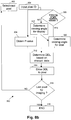
- Fig. 8b In an alternative method 350, as illustrated in Fig. 8b , it is assumed that the viewing angle dependency is not independent of the spatial location on the display system such that the two corrections, for greyscale level and for viewing angle, are coupled and need to be performed at the same time. In other words, this method can be used for a general situation where it is assumed that each position on the display can have a different viewing-angle behaviour.
- the method comprises the same steps as method 300, but the viewing angle information is specified for each pixel.
- step 320 is performed wherein the viewing angle information for the display system is used to determine the viewing angle information for the pixel selected in step 302 and identified in step 304.
- This lookup-table takes as input the P-value (m-bit), an identification of the pixel like e.g. the location of the pixel (row & column, number or zone number) and the viewing angle for the pixel.
- the output is the DDL that gives best performance for that specific situation.
- Some medical displays are used both in portrait and landscape orientation. This means that the display can be physically rotated 90°. In that case it is of course not necessary to store the viewing angle behaviour for both orientations.
- the viewing behaviour can be measured for the orientation that is mostly used (portrait) and if the display is changed to landscape orientation then the viewing angle data can be rotated 90° and used.
- Examples of such functions can be polynomials; a set of coefficients of cosines functions, ....
- Another possibility is to reference all characterisation and/or correction data relative to a chosen typical data-set. For instance reference can be made relative to the correction/characterisation of the centre of the display. Typically this technique will require less storage area, as in this case the values of the correction coefficients will be smaller thus resulting in less bits needed to store them.
- a variant to the reference data/characterisation is to delta-encode the characterisation/correction data, i.e. the difference with the previous data, in this case the neighbouring location or viewing angle is used. Also symmetry in the data can be exploited to reduce the storage requirements.
- the viewing angle behaviour will have rather good point symmetry around the on-axis point.
- a somewhat more complex solution is to group or classify the characterisation or correction data into a number of reference classes with the intention to significantly reduce the required storage area. It can for instance be envisaged to group pixels or zones that require the same (or approximately the same, within a pre-set limit) spatial compensation. Instead of storing that compensation data then for each pixel or zone, a small reference class can be stored for each pixel or zone and the actual larger compensation data can be stored only once. The same holds for the viewing angle behaviour. Of course this clustering can be done for spatial compensation and/or viewing angle compensation independently or together. For people skilled in the art it will be clear that lots of algorithms exist to group elements in classes, such as vector quantization, neural networks....
- lookup tables and circuitry based on interpolation circuits or mathematical functions or a combination thereof can be used. It is furthermore to be noted that it is also possible to combine existing lookup-tables used for image enhancement, with the lookup-tables or compensation needed for the present invention.
- the correction methods and algorithms described in the present invention can be executed both real-time, i.e. during driving of he matrix display while displaying images, or offline, i.e. not during driving of the matrix display so as to display the images.
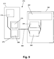
- Fig. 9 a number of different locations to perform a real-time correction in a system 370 is shown.
- the system 370 comprises a host computer 372 and a display system 390.
- the host computer 372 can be any conventional computer providing a significant high quality central processing unit CPU 374 and a significant high quality graphical card 376.
- the graphical card 376 comprises a software component, which typically can be firmware 378 and a hardware component 380.
- the pixel correction can be done by the CPU 374 of the host computer 372, such as for example by means of the driver code of the graphical card 376 or with a specific application or embedded in a viewing application.
- pixel correction also can be performed in the graphical card 376 itself, either in a hardware component 380 of the graphical card 376, or in a firmware component 378 of the graphical card 380.
- the pixel correction also can be performed in the display system 390 itself, either in display hardware 394 or in display firmware 396.
- a further alternative is to perform the pixel correction on the signal transmitted between the graphical card 376 and the display system 390, i.e. is somewhere during this transmission in the transmission channel 398.
- a first component of the system 370 e.g. the CPU 374 of the host computer 372
- a second component of the system 370 e.g. in the display hardware 394.
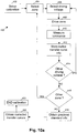
- Fig. 10a , Fig. 10b and Fig. 10c give an overview of different embodiments of methods for calibration that can be used according to the present invention.
- the calibration method 400 does not include viewing angle dependent measurements but the viewing angle can be introduced from e.g. theoretical considerations or it can be assumed that the viewing-angle behaviour is proportional to the viewing-angle behaviour of a reference display system of the same type. In that case the viewing angle dependency can be characterised once and used for all panels of that type.
- the calibration method 400 for this embodiment involves the following steps.
- step 402 the calibration procedure is set up. This is typically done during manufacturing of the system, but it also can be performed at the place of use of the display system, e.g. if due to heating, aging or human intervention, such as e.g. adjusting of the backlighting, the characteristics of the system have been changed.
- step 404 a zone or a pixel is selected for calibration. As described above, the calibration can either be done on zones in which the pixels are grouped or the calibration can be done on individual pixels or even on sub-pixels.
- the method then proceeds to step 406 wherein a driving voltage, referred to as digital driving level DDL in the DICOM specification, is selected.
- DDL digital driving level
- the condition to be fulfilled is that significant accurate information is to be obtained to substantially obtain the details of the native transfer curve.
- interpolation can be used between measurement results.
- the selected driving voltage is then used to drive the selected zone or the pixel in step 408. As discussed above, if a zone is driven, this can either be a central pixel of a zone or a number of pixels in the zone, or it can be all pixels in the zone. Other specific pixel selections from the group of pixels forming a zone also can be used, as will be clear for a person skilled in the art.
- the luminance of the driven zone is measured using a luminance detection system.
- step 412 The result of this measurement is stored in step 412, after which, in step 414, it is checked if all driving voltages for the selected zone are already used for obtaining the native transfer curve information. in this way, by driving the zone at different driving voltages, measuring the corresponding luminance level and storing the couples (driving voltage, luminance level) the native transfer curve information is obtained and stored. If all needed information about the native transfer curve for the currently selected zone is obtained, method 400 proceeds to step 416, where it is decided if another zone/pixel needs to be measured. If this is the case, the method returns to step 404, for characterising another zone or pixel. Otherwise all spatial information about the native transfer curves for the display system is obtained and method 400 proceeds to step 418.
- the information of the greyscale level display standard to be enforced is obtained, in the luminance range needed, i.e. depending on the measured luminance values.
- the corrected transfer curves for the different pixels/zones of the display system are obtained by fitting the results to the greyscale level display standard information to be enforced.
- the viewing angle information for the display system which may be based on theoretical considerations or on measurements on a prototype display system, is also introduced, thus resulting in corrected transfer curves for the different pixels/zones and for different viewing angles.
- a more extended method 440 for calibrating as shown in Fig. 10b , additional viewing angle measurements are performed, thus allowing to optimise the enforced greyscale level display standard conformance for viewing angle dependency.
- Fig. 10b method steps having the same reference signs as in Fig. 10a are as explained above, and are not explained here in detail.
- step 406 After selection of the driving voltage in step 406, additional steps 424 and 426 are introduced such that for each zone/pixel and for each driving voltage the native transfer curve information can be stored for a number of viewing angles.
- the number of viewing angles used to obtain significant accurate transfer curve information depends on the display system used.
- the viewing angles can be divided into zones and interpolation can be used to obtain an approximate transfer curve for all viewing angles. Using interpolation allows to reduce the measurement time.
- An alternative method 460 for calibrating, as shown in Fig. 10c allows to measure the viewing angle dependency for one zone/pixel and uses this viewing angle dependency as the general viewing angle dependency.
- method steps having the same reference signs as in any of Fig. 10a or Fig. 10b are as explained above, and are not explained here in detail.
- step 428 it is decided whether the viewing angle dependency for the selected driving voltage is known and if not, the method proceeds to step 424 such that the viewing angle dependency is measured for this zone/pixel. Further in the method, if another zone is selected, in decision step 428, the viewing angle dependency will be decided to be known from previous measurements and the viewing angle dependency will not be recorded anymore. The viewing angle dependency measured for the first zone will then be used in step 420 to obtain the appropriate corrected transfer curves for all pixels/zones. This significantly decreases measurement time since the viewing angle measurements do not need to be performed at multiple locations on the display.
- the system may comprise a detection system for detecting the status of the back-light.
- a detection system for detecting the status of the back-light This can be e.g. a detector that allows detection of the emission from the screen such that the intensity of the backlighting can be tested and such that the calibration information for conformance with the DICOM standard, or any other grey-level display standard, can be adjusted accordingly.
- changes of the native transfer curve of the display can be detected., if e.g. a photo-sensor is placed so that it measures on the front-side of the display area, i.e. the viewing side of the display area.
- the environmental conditions in the room for viewing can be measured by using a detection system somewhere in the room or preferably in the housing of the display so that the amount of environmental light that is present can be measured, as this will alter the viewing conditions and will influence the DICOM-conformance of the display.
- a detection system somewhere in the room or preferably in the housing of the display so that the amount of environmental light that is present can be measured, as this will alter the viewing conditions and will influence the DICOM-conformance of the display.
- An example is given for a medical LCD-panel that has all pixels in dark state having a luminance of approximately 0.5 cd/m 2 and ambient light having a luminance between 0.1 cd/m 2 , i.e. a completely dark radiology room for instance for mammography, up to 30 cd/m 2 in a normal office.
- the calibration information used for adjusting to DICOM-conformance, or to conformance to any other greyscale or colour display standard can be adjusted to influences of external factors. Detection at different locations on the display is possible but not always necessary, as the effects may be proportional for all spatial locations at the display and may be proportional for all viewing angles of the display.
- the present invention can be applied to any situation where the transfer curve of each pixel or zone under all or some viewing angles needs to fulfil certain mathematical relationships.
- the transfer curve and more particularly the luminance value of each pixel or zone needed to follow a certain mathematical curve as described by " DICOM / NEMA supplement 28 greyscale standard display function".
- DICOM / NEMA supplement 28 greyscale standard display function A simple extension to this model can be that for small viewing angles the transfer curve indeed needs to follow that mathematical relationship but for larger viewing angles the transfer curve is changed to a constant function.
- the spatial and viewing angle correction can also be adapted to generate the lower number of greyscale values. Because of the lower number of output greyscale values it will typically be easier to comply with an enforced display standard. Warning the user or reducing the number of output greyscale values may be e.g. performed when the viewing angle is outside the preferred ranges as described above. Warning the user that the display behaviour is not acceptable anymore could also be done by other means such as, but not limited to: showing a pattern on the screen (such as a text or an image, e.g.
- a checkerboard pattern or overlaying the current screen contents, a sound, a visual signal such as one or more LEDs (control lights) or colour changes of LEDs, sending a message to the user through a communication medium such as telephone or gsm or sms or email, sending a message to a software application such as a QA (Quality Assurance) application or a PACS (Picture Archiving and Communication System) viewing application, writing a file on the hard disk of the PC, logging an event, etc...
- a communication medium such as telephone or gsm or sms or email
- a software application such as a QA (Quality Assurance) application or a PACS (Picture Archiving and Communication System) viewing application, writing a file on the hard disk of the PC, logging an event, etc...
- not acceptable display behaviour is not limited to the isolated display: it should be seen as a combination of display system (display, graphical card, processing unit such as e.g. PC, viewing application, quality of the link (bit error rate) between PC and display), environmental conditions (ambient light, actual contrast of the display system including ambient light, temperature, humidity, electromagnetic interference levels, ...), the user that is actually using the display, etc... For instance, but not limited thereto: the user could be warned by any suitable means that the display behaviour is not acceptable anymore if the ambient light in the room is too high, or if the temperature is outside the display spec, and the threshold levels (when the display behaviour is acceptable and when not) could even be depending on the user actually using the display at that moment. Each user could for instance select other threshold levels for "acceptable display behaviour" or these threshold levels could be selected based on characteristics (such as quality of eyes, level of training or experience, ...) of each individual user or groups of users.
- display system display, graphical card, processing unit such as e.g. PC, viewing application, quality
- pre-correction could also include making the performance of the display system tolerant to parameter changes.
- settings of the display system (display itself, graphical board, host PC, software applications, ...) are chosen so that the performance of the display system stays as stable (high) as possible, preferably within accepted behaviour, if a parameter relevant for the quality of a displayed image changes.
- Parameters relevant for the quality of a displayed image that can change are for example, but not limited to: the viewing angle(s) under which the user(s) looks at the display, the intensity of the ambient light, the colour point of the ambient light, the luminance of the backlight, the colour point of the backlight, the ambient or display system temperature, the humidity of the environment, ...
- display systems may be provided that have a performance that is tolerant to changes in other parameters relevant for the quality of a displayed image as well, such as e.g. a change in intensity of the ambient light etc.
- the viewing angle of the user with respect to the display can be represented by two angles: a horizontal and a vertical angle.
- an enforced greyscale or colour display standard compliant system such as e.g. a DICOM compliant display system
- FIG. 11 represents the probability that a user will look at the display under a horizontal viewing angle x1 and under a vertical viewing angle y1.
- the point w(x1, y1) in Fig. 11 represents the importance of viewing angle (x1, y1).
- the goal is to find a calibration curve that will make sure that performance of the display system is maximized, and this for every relevant viewing angle. This means that a curve needs to be found that results into standard display function compliance (for instance but not limited to DICOM) for as many points of the (x, y) plot as possible, where the value of each point (importance of each point) is weighted with the assigned value (probability or importance of that point) for that point.
- DICOM standard display function compliance
- the problem is then to find a DICOM calibration curve that makes sure that as many points as possible in the (x, y) plot will be compliant to the enforced DICOM standard, whereby the points in the (x, y) plot are weighted according to importance.
- weights could be for instance that on-axis viewing is very likely, and so has high weight, but also small angles in horizontal and near horizontal direction are important and therefore also have rather high weights. It is possible that points in the (x, y) diagram have zero weight (if they are of no importance) or even negative weights (if it is not desired that those points comply with the standard, for instance because a designer does not want the user to use the display for those angles).
- assigning the weights to the points in the (x, y) diagram can be done in any way and that the assigned weights can be negative, zero or positive numbers of any precisions such as but not limited to integers, floating point numbers, fixed point numbers, ...
- the metric that determines whether a specific calibration curve, e.g. a calibration LUT or an analytical expression thereof, results into compliance with the desired standard display function can be an arbitrary function that can give as output both negative, zero and positive numbers. For example but not limited to: negative numbers could mean that this calibration curve results in non-compliance with the standard for that angle, zero could mean that it is compliant both only just within specs, a positive number could mean that the calibration LUT results in good compliance with the standard for that angle. It is to be noted that the result of the metric that determines whether a specific calibration curve can be of any precision such as, but not limited to, integer values, floating point values, fixed point values, ...
- the parameter space comprises the values of the calibration curve, e.g. calibration LUT or an analytical expression thereof.
- the values of the calibration curve need to be chosen so that the weighted sum of the result of the cost function over all (or some pre-determined, chosen) points in the (x, y) diagram is maximized.
- a parameter vector L needs to be selected, L being a set of parameters that need to be optimised.
- a cost function or metric C is established, describing the compliance of parameter vector L for the parameter under consideration compared to a desired standard, for example C(x, y; L) is the cost function describing the compliance of parameter vector L from the calibration curve for viewing angle (x, y), compared to the desired standard.
- the parameter vector L needs to be selected so that the weighted sum of the result of the cost function C for each point and that vector L over (some part of) a space (for instance 2 dimensional: horizontal and vertical viewing angle, for instance 3 dimensional: horizontal and vertical viewing angle and white luminance of the display, for instance 4 dimensional: horizontal and vertical viewing angle and white luminance of the display and ambient light intensity, ...) is maximized, i.e. max imize L ⁇ areaA w x y C x y L , or thus find those L that maximize the weighted sum of the const function C and this for an area A in the (x,y) space..
- this technique can be used if no viewing angle measurement system is available. Then the set of viewing angles that are important is estimated, e.g. a range of standard viewing angles is selected, such as for example between -20° and +20°, and the optimal calibration curve, e.g. represented as a calibration LUT or an analytical expression thereof, for that set of viewing angles is calculated.
- the optimal calibration curve e.g. represented as a calibration LUT or an analytical expression thereof
- the above technique can still be used to solve inaccurate viewing angle measurements. Indeed, if the calibration curve would still be optimised for a set of angles that are near to the measured viewing angle, i.e. within a range of a few degrees from the measured viewing angle, preferably within a range of 10 degrees or less from the measured viewing angle, then the display performance with that calibration curve will actually be acceptable with a bigger degree of certainty even if the viewing angle measurement was not completely accurate.
- the exact selection of this set of viewing angles and the corresponding weights for these points in the (x, y) diagram do not limit the present invention. It is clear for someone skilled in the art that a lot of variations to select this set and corresponding weights are possible.
- Fig. 12 a further example of the above method is illustrated, in which different weights are assigned to different points in the (x,y) space.
- viewing angles around (0,0) i.e. viewing angles which are on-axis both in horizontal direction and vertical direction, or which are close to on-axis, have a first, high weight value because the user is likely to view on-axis or closely there to.
- Viewing angles which are between 10° to 20° off-axis either in horizontal or in vertical direction, or in both directions have a second weight value, the second weight value being lower than the first weight value.
- Higher dimension parameter vectors may comprise for instance, but are not limited to (at least combinations or subsets are possible): multidimensional lookup tables, peak luminance of the display, calibrated luminance of the display, colour point of the display, ambient light intensity, colour point of the ambient light, ambient temperature, ambient humidity, etc...
- Higher dimensional search spaces may comprise for instance, but are not limited to (at least combinations or subsets are possible): horizontal and vertical viewing angle, distance to the display, ambient light intensity, colour point of the ambient light, ambient temperature, etc...
- the present invention furthermore is not limited to greyscale displays.
- a reference work for colour imaging is "Colour Vision and Colourimetry, Theory and Applications” by Daniel Malacara.
- the invention not being limited thereto, the use of a colour display to view greyscale images is described. In that case the input of the display system is a greyscale image, but the display system itself has colour possibilities.
- An equivalent mathematical description of the "DICOM / NEMA supplement 28 greyscale standard display function" can then be used.
- each pixel for example consists of three sub-pixels
- the mathematical description will then involve a combination of the three transfer curves of the individual colour sub-pixels and will state that a mathematical function of those three transfer curves, which is used to calculate the luminance value from individual colours, for each pixel should follow a certain curve, i.e. the greyscale standard display function.
- a certain curve i.e. the greyscale standard display function.
- a resulting output having the same luminance but a different colour point, as described for example - but not limited to - by CIE colour co-ordinates x,y, can be obtained.
- a specific colour behaviour can be used to obtain a specific colour behaviour, which is to be obtained in addition to the greyscale standard display function.
- a first example of such a specific colour behaviour is selecting a constant specific colour point for the greyscale values.
- the pixels should follow the specific luminance greyscale standard curve, e.g. the DICOM GSDF, and the colour co-ordinates should remain at a specific, user-selected, value when following this greyscale standard curve.
- Another example of specific colour behaviour is that, together with the greyscale standard to be complied with, a change in colour is obtained. This can be done by e.g. forcing the colour co-ordinates to comply with a specific curve, e.g.
- the present invention also relates to a method and system whereby for all pixels and viewing angles, or for a limited number of zones or viewing angles, when changing the input greyscale stimulus from minimum to maximum, the output luminance of the display system complies with a greyscale standard to be followed and for all pixels and viewing angles, or for a limited number of zones or viewing angles possibly different from the ones described above, when changing the input greyscale stimulus, the output of the display system, more specifically the colour co-ordinates comply with a specific selected mathematical curve (for instance a constant, a linear curve between two colour points, ). It is to be noted that the mathematical curve does not need to be constant but that it also can be time-dependent or depend on other parameters such as e.g. external measurement data, external factors, ...
- R,G,B values of the display system to colour co-ordinates such as the CIE x,y co-ordinates
- colour co-ordinates such as the CIE x,y co-ordinates
- This can be e.g. done by measuring the colour-co-ordinates of all or a selection of R,G,B values and applying the inverse transformation if a conversion from R,G,B to x,y co-ordinates is needed.
- Another possibility is to theoretically deduce the colour co-ordinates for all R,G,B display values based on a limited number of measurements, such as the transfer curve of the R,G and B sub pixels and the colour co-ordinates of the fully-on and fully-off state of the R,G and B sub pixels.
- the invention also can be used in colour critical images.
- the display input is a colour image, as described for example by R,G,B values in a specific colour profile
- the display system also allows colour output.
- the goal is then to improve the conformance of the display output image to the user selected colour profile and this by applying spatial and viewing-angle corrections.
- a mathematical relationship can be defined that states that the combination of the three transfer curves of all pixels/zones should result in a specific colour profile. This mathematical relationship allows calculating x,y-colour coordinates from the three colour transfer curves together.
- the input image typically is specified in R,G,B colour co-ordinates in a specific colour profile.
- the specific colour profile can be user-defined and may easily be converted to standard colour co-ordinates such as e.g. the CIE X,Y,Z-system.
- the image to be displayed typically is specified in a standard colour co-ordinate system that differs from the native R,G,B output colour profile of the display system.
- a spatial and viewing-angle correction system can be applied in the same way as described for greyscale curves.
- the characterisation data that defines the output - as specified in a standard colour co-ordinate system - as a function of the drive signals the spatial location at the display and the viewing angle can be measured or calculated mathematically.
- the output can be e.g. specified in the CIE X,Y, Z colour co-ordinate system, and the drive signals can be e.g. given in R, G and B values.
- Yet another example is for displaying images where absolute colour co-ordinates are less important but differences between colours are important.
- the spatial and off-axis correction are applied such that differences between colours, as expressed e.g. in colour JNDs, are displayed in the same way for all locations on the display and for all viewing angles.
- the present invention relates not only to a system wherein an optimised conformance to an enforced greyscale or colour display standard may be provided, it also relates to the corresponding method for adjusting images and displaying adjusted images conform an enforced greyscale or colour display standard and it furthermore also relates to the methods described for calibrating a system such that it is conform an enforced greyscale or colour display standard.
- the correction method to obtain improved enforced display standard behaviour allows correction for the individual greyscale or colour behaviour of each pixel/zone.
- the obtained transfer curve for each pixel/zone is such that each of those transfer curves fulfils the enforced display standard behaviour.
- the obtained transfer curves for each pixel/zone do not enforce all pixels/zones to the same minimum and maximum brightness and even for pixels/zones having the same minimum and maximum brightness, the correction curves may differ to obtain an optimum individual enforced display standard behaviour. In the present invention, therefore, no equal transfer curves for each pixel/zone are provided, but the transfer curve for each pixel/zone is optimised individually.
- a "time-dependent" correction is provided, depending on at least some circumstances in which the display system is used.
- the applied correction furthermore allows adjusting the degree of output greyscale depth, e.g. by decreasing the output greyscale depth if for certain large viewing angles no compliance is obtained with the enforced display standard.
Claims (21)
- Procédé pour corriger de la non-conformité dans des valeurs de niveau de gris ou de couleur d'une pluralité de zones d'éléments de pixel dans un afficheur matriciel (200), chaque zone (202) d'éléments de pixel (204) étant corrigée par une fonction d'étalonnage différente (704,705), le procédé comprenant :pour chaque zone (202) d'éléments de pixel indépendamment,- le stockage de données de caractérisation (106) caractérisant la non-conformité dans des valeurs de niveau de gris ou de couleur de la zone (202) d'éléments de pixel comme une fonction de ses signaux de pilotage (112),- la correction, selon les données de caractérisation (106), des signaux de pilotage de ladite zone d'éléments de pixel afin d'obtenir un niveau de gris ou de couleur, ladite correction étant effectuée sur la base d'une valeur d'entrée (104) de la valeur de niveau de gris ou de couleur à afficher et d'un angle d'observation sous lequel la zone (202) d'éléments de pixel est ou doit être observée,caractérisé en ce que ladite correction s'effectue par rapport à une norme d'affichage mise en application de niveau de gris ou de couleur, et ledit niveau de gris ou de couleur est conforme à ladite norme d'affichage mise en application de niveau de gris ou de couleur, et dans lequel, si l'angle d'observation, sous lequel la zone d'éléments de pixel est observée, est à l'extérieur d'une plage prédéterminée, le procédé comprend en outre l'ajustement de la correction en réduisant le nombre de niveaux de gris ou de couleur de sorte qu'un utilisateur est averti que regarder à partir de cet angle n'est pas recommandé.
- Procédé selon la revendication 1, dans lequel l'ajustement de la correction comprend le changement du contenu d'affichage pour un niveau de gris uniforme.
- Procédé selon l'une quelconque des revendications précédentes, dans lequel une zone (202) d'éléments de pixel consiste en un élément de pixel.
- Procédé selon l'une quelconque des revendications 1 à 3, dans lequel une zone (202) d'éléments de pixel comprend une pluralité d'éléments de pixel, chaque élément de pixel d'une zone se voyant attribuer une même donnée de caractérisation (106).
- Procédé de correction selon l'une quelconque des revendications précédentes, dans lequel ledit angle d'observation sous lequel l'afficheur matriciel est ou doit être observé est sélectionnable par un utilisateur.
- Procédé de correction selon l'une quelconque des revendications 1 à 4, dans lequel ledit angle d'observation sous lequel l'afficheur matriciel est ou doit être observé est mesuré en utilisant un système de détection.
- Procédé de correction selon l'une quelconque des revendications précédentes, dans lequel lesdites données de caractérisation comprennent en outre au moins une de la dépendance à l'intensité de rétroéclairage, de la dépendance à un paramètre environnemental.
- Procédé selon la revendication 7, dans lequel ledit paramètre environnemental est l'intensité de lumière environnementale.
- Procédé de correction selon l'une quelconque des revendications 1 à 8, dans lequel ladite correction du signal de pilotage (112) est effectuée sur la base de l'utilisation d'une table de correspondance.
- Procédé de correction selon l'une quelconque des revendications 1 à 9, dans lequel ladite correction du signal de pilotage (112) est effectuée au moins partiellement sur base de l'utilisation d'une fonction mathématique.
- Procédé selon l'une quelconque des revendications précédentes, comprenant en outre la production des données de caractérisation à partir d'images capturées provenant de zones individuelles d'éléments de pixel.
- Procédé selon la revendication 11, dans lequel la production de données de caractérisation comprend la construction d'une carte de profil d'élément de pixel représentant des données de caractérisation pour chaque élément de pixel de l'afficheur matriciel.
- Procédé de correction selon l'une quelconque des revendications 1 à 12, dans lequel la correction est effectuée en temps réel pendant le pilotage de l'afficheur matriciel tout en affichant des images.
- Procédé de correction selon l'une quelconque des revendications 1 à 12, dans lequel la correction est effectuée hors ligne à un moment autre que pendant le pilotage de l'afficheur matriciel tout en affichant des images.
- Procédé de correction selon l'une quelconque des revendications 1 à 14 dans lequel ladite norme d'affichage mise en application de niveau de gris est l'Imagerie et les Communications Numériques en Médecine, désignée par DICOM, norme publiée par l'Association Nationale de Fabricants Électriques.
- Système (370) pour corriger de la non-conformité dans des valeurs de niveau de gris ou de couleur d'une pluralité de zones (202) d'éléments de pixel (204) dans un afficheur matriciel (200), le système (370) étant conçu pour déterminer un angle d'observation d'un utilisateur par rapport à l'afficheur matriciel (200), le système comprenant :- un moyen de mémoire pour stocker des données de caractérisation caractérisant la non-conformité dans des valeurs de niveau de gris ou de couleur de la pluralité de zones (202) d'éléments de pixel (204) comme une fonction de ses signaux de pilotage (112) et comme une fonction de l'angle d'observation sous lequel la zone d'éléments de pixel doit être observée,- un dispositif de correction pour corriger, selon les données de caractérisation, des signaux de pilotage vers la zone d'éléments de pixel pour obtenir un niveau de niveau de gris ou de couleur,caractérisé en ce que ladite non-conformité de correction s'effectue par rapport à une norme d'affichage mise en application de niveau de gris ou de couleur et ledit niveau de gris ou de couleur obtenu est conforme à la norme d'affichage mise en application de niveau de gris ou de couleur, et ledit dispositif de correction étant conçu, si l'angle d'observation déterminé est à l'extérieur d'une plage prédéterminée, pour ajuster ces signaux de pilotage en réduisant le nombre de niveaux de gris ou de niveaux de couleur de sorte qu'un utilisateur est averti que regarder à partir de cet angle n'est pas recommandé.
- Système selon la revendication 16, dans lequel le dispositif de correction est conçu pour ajuster les signaux de pilotage à la zone d'éléments de pixel afin d'obtenir un seul niveau de gris ou de couleur.
- Système selon l'une quelconque des revendications 16 ou 17, comprenant en outre un dispositif de caractérisation pour produire des données de caractérisation pour un certain nombre de zones d'éléments de pixel.
- Système selon la revendication 18, dans lequel ledit dispositif de caractérisation comprend un dispositif de capture d'image pour produire une image des éléments de pixel de l'afficheur matriciel.
- Système selon l'une quelconque des revendications 16 à 19, dans lequel le dispositif de correction comprend un dispositif de détermination d'angle d'observation pour déterminer l'angle d'observation d'un utilisateur par rapport à un système d'affichage.
- Dispositif d'affichage matriciel (200) pour afficher une image, le dispositif d'affichage matriciel comprenant : une pluralité de zones (202) d'éléments de pixel (204) et comprenant en outre un système selon l'une quelconque des revendications 16 à 20.
Priority Applications (1)
| Application Number | Priority Date | Filing Date | Title |
|---|---|---|---|
| EP05779896.9A EP1735767B1 (fr) | 2004-04-15 | 2005-04-15 | Procédé et dispositif pour améliorer la conformité d'un panneau d' affichage avec un standard d'affichage dans toute la surface d'affichage et pour différents angles visuels |
Applications Claiming Priority (3)
| Application Number | Priority Date | Filing Date | Title |
|---|---|---|---|
| EP04447098A EP1587049A1 (fr) | 2004-04-15 | 2004-04-15 | Procédé et dispositif pour améliorer la conformité d'un panneau d' affichage avec un standard d'affichage dans toute la surface d'affichage et pour différents angles visuels |
| EP05779896.9A EP1735767B1 (fr) | 2004-04-15 | 2005-04-15 | Procédé et dispositif pour améliorer la conformité d'un panneau d' affichage avec un standard d'affichage dans toute la surface d'affichage et pour différents angles visuels |
| PCT/EP2005/004151 WO2005101355A1 (fr) | 2004-04-15 | 2005-04-15 | Procede et dispositif permettant d'ameliorer la conformite d'une norme d'affichage spatial et hors axe |
Publications (2)
| Publication Number | Publication Date |
|---|---|
| EP1735767A1 EP1735767A1 (fr) | 2006-12-27 |
| EP1735767B1 true EP1735767B1 (fr) | 2017-10-04 |
Family
ID=34933022
Family Applications (2)
| Application Number | Title | Priority Date | Filing Date |
|---|---|---|---|
| EP04447098A Withdrawn EP1587049A1 (fr) | 2004-04-15 | 2004-04-15 | Procédé et dispositif pour améliorer la conformité d'un panneau d' affichage avec un standard d'affichage dans toute la surface d'affichage et pour différents angles visuels |
| EP05779896.9A Active EP1735767B1 (fr) | 2004-04-15 | 2005-04-15 | Procédé et dispositif pour améliorer la conformité d'un panneau d' affichage avec un standard d'affichage dans toute la surface d'affichage et pour différents angles visuels |
Family Applications Before (1)
| Application Number | Title | Priority Date | Filing Date |
|---|---|---|---|
| EP04447098A Withdrawn EP1587049A1 (fr) | 2004-04-15 | 2004-04-15 | Procédé et dispositif pour améliorer la conformité d'un panneau d' affichage avec un standard d'affichage dans toute la surface d'affichage et pour différents angles visuels |
Country Status (7)
| Country | Link |
|---|---|
| US (1) | US8228348B2 (fr) |
| EP (2) | EP1587049A1 (fr) |
| JP (1) | JP4890441B2 (fr) |
| KR (1) | KR101122982B1 (fr) |
| CN (1) | CN100504980C (fr) |
| TW (1) | TW200540793A (fr) |
| WO (1) | WO2005101355A1 (fr) |
Families Citing this family (99)
| Publication number | Priority date | Publication date | Assignee | Title |
|---|---|---|---|---|
| CA2443206A1 (fr) | 2003-09-23 | 2005-03-23 | Ignis Innovation Inc. | Panneaux arriere d'ecran amoled - circuits de commande des pixels, architecture de reseau et compensation externe |
| CA2472671A1 (fr) | 2004-06-29 | 2005-12-29 | Ignis Innovation Inc. | Procede de programmation par tensions pour affichages a del excitees par courant |
| US9275579B2 (en) | 2004-12-15 | 2016-03-01 | Ignis Innovation Inc. | System and methods for extraction of threshold and mobility parameters in AMOLED displays |
| US8576217B2 (en) | 2011-05-20 | 2013-11-05 | Ignis Innovation Inc. | System and methods for extraction of threshold and mobility parameters in AMOLED displays |
| US9280933B2 (en) | 2004-12-15 | 2016-03-08 | Ignis Innovation Inc. | System and methods for extraction of threshold and mobility parameters in AMOLED displays |
| WO2006063448A1 (fr) | 2004-12-15 | 2006-06-22 | Ignis Innovation Inc. | Procede et systeme de programmation, de calibrage et de commande d'un affichage a dispositif electroluminescent |
| US10012678B2 (en) * | 2004-12-15 | 2018-07-03 | Ignis Innovation Inc. | Method and system for programming, calibrating and/or compensating, and driving an LED display |
| US9799246B2 (en) | 2011-05-20 | 2017-10-24 | Ignis Innovation Inc. | System and methods for extraction of threshold and mobility parameters in AMOLED displays |
| US10013907B2 (en) | 2004-12-15 | 2018-07-03 | Ignis Innovation Inc. | Method and system for programming, calibrating and/or compensating, and driving an LED display |
| CA2504571A1 (fr) * | 2005-04-12 | 2006-10-12 | Ignis Innovation Inc. | Methode rapide de compensation des defauts d'uniformite dans les afficheurs oled |
| US20140111567A1 (en) | 2005-04-12 | 2014-04-24 | Ignis Innovation Inc. | System and method for compensation of non-uniformities in light emitting device displays |
| US9171500B2 (en) | 2011-05-20 | 2015-10-27 | Ignis Innovation Inc. | System and methods for extraction of parasitic parameters in AMOLED displays |
| CA2496642A1 (fr) | 2005-02-10 | 2006-08-10 | Ignis Innovation Inc. | Methode d'attaque a courte duree de stabilisation pour afficheurs a diodes organiques electroluminescentes (oled) programmes par courant |
| US8041093B2 (en) * | 2005-04-22 | 2011-10-18 | General Electric Company | System and method for definition of DICOM header values |
| CN102663977B (zh) | 2005-06-08 | 2015-11-18 | 伊格尼斯创新有限公司 | 用于驱动发光器件显示器的方法和系统 |
| US7605785B2 (en) | 2005-07-12 | 2009-10-20 | Eastman Kodak Company | Black level uniformity correction method |
| CA2518276A1 (fr) | 2005-09-13 | 2007-03-13 | Ignis Innovation Inc. | Technique de compensation de la degradation de luminance dans des dispositifs electroluminescents |
| US20070120763A1 (en) * | 2005-11-23 | 2007-05-31 | Lode De Paepe | Display system for viewing multiple video signals |
| TW200746022A (en) | 2006-04-19 | 2007-12-16 | Ignis Innovation Inc | Stable driving scheme for active matrix displays |
| US7592996B2 (en) | 2006-06-02 | 2009-09-22 | Samsung Electronics Co., Ltd. | Multiprimary color display with dynamic gamut mapping |
| CA2556961A1 (fr) | 2006-08-15 | 2008-02-15 | Ignis Innovation Inc. | Technique de compensation de diodes electroluminescentes organiques basee sur leur capacite |
| US8127233B2 (en) * | 2007-09-24 | 2012-02-28 | Microsoft Corporation | Remote user interface updates using difference and motion encoding |
| US8400385B2 (en) * | 2007-12-21 | 2013-03-19 | Hong Kong Applied Science and Technology Research Institute Company Limited | Method for enhancing an image displayed on an LCD device |
| EP2091227A1 (fr) | 2008-02-15 | 2009-08-19 | Thomson Licensing | Procédé pour l'ajustement de réglages d'un dispositif de reproduction de couleurs |
| JP4807371B2 (ja) * | 2008-03-27 | 2011-11-02 | ソニー株式会社 | 液晶表示装置 |
| TW200947415A (en) * | 2008-05-08 | 2009-11-16 | Chunghwa Picture Tubes Ltd | Display method of liquid crystal display device |
| US20100060667A1 (en) * | 2008-09-10 | 2010-03-11 | Apple Inc. | Angularly dependent display optimized for multiple viewing angles |
| US8625921B1 (en) * | 2008-09-26 | 2014-01-07 | Google Inc. | Method for image processing using local statistics convolution |
| EP2329487B1 (fr) | 2008-09-30 | 2016-05-25 | Dolby Laboratories Licensing Corporation | Systèmes et procédés permettant d'appliquer un gamma adaptatif à un traitement d'image afin d'obtenir des affichages ayant une plage dynamique élevée et une forte luminosité |
| TWI409763B (zh) * | 2008-11-13 | 2013-09-21 | Chi Mei El Corp | 影像補償模組、有機發光二極體顯示面板、有機發光二極體顯示裝置及影像補償方法 |
| JP5354265B2 (ja) * | 2009-01-22 | 2013-11-27 | ソニー株式会社 | 液晶表示装置 |
| US10319307B2 (en) | 2009-06-16 | 2019-06-11 | Ignis Innovation Inc. | Display system with compensation techniques and/or shared level resources |
| CA2688870A1 (fr) | 2009-11-30 | 2011-05-30 | Ignis Innovation Inc. | Procede et techniques pour ameliorer l'uniformite d'affichage |
| US9311859B2 (en) | 2009-11-30 | 2016-04-12 | Ignis Innovation Inc. | Resetting cycle for aging compensation in AMOLED displays |
| US9384698B2 (en) | 2009-11-30 | 2016-07-05 | Ignis Innovation Inc. | System and methods for aging compensation in AMOLED displays |
| CA2669367A1 (fr) | 2009-06-16 | 2010-12-16 | Ignis Innovation Inc | Technique de compensation pour la variation chromatique des ecrans d'affichage . |
| JP5280948B2 (ja) * | 2009-06-25 | 2013-09-04 | 三菱電機株式会社 | 映像表示装置、光度補正データ生成装置および光度補正データ生成方法 |
| TWI405181B (zh) * | 2009-07-29 | 2013-08-11 | Novatek Microelectronics Corp | 增進顯示裝置之亮度均勻性的校正方法及相關裝置 |
| US10996258B2 (en) | 2009-11-30 | 2021-05-04 | Ignis Innovation Inc. | Defect detection and correction of pixel circuits for AMOLED displays |
| US8803417B2 (en) | 2009-12-01 | 2014-08-12 | Ignis Innovation Inc. | High resolution pixel architecture |
| US20120249622A1 (en) * | 2009-12-02 | 2012-10-04 | Sharp Kabushiki Kaisha | Display device and display method |
| CA2687631A1 (fr) | 2009-12-06 | 2011-06-06 | Ignis Innovation Inc | Mecanisme de commande a faible puissance pour applications d'affichage |
| US10176736B2 (en) | 2010-02-04 | 2019-01-08 | Ignis Innovation Inc. | System and methods for extracting correlation curves for an organic light emitting device |
| US20140313111A1 (en) | 2010-02-04 | 2014-10-23 | Ignis Innovation Inc. | System and methods for extracting correlation curves for an organic light emitting device |
| US10089921B2 (en) | 2010-02-04 | 2018-10-02 | Ignis Innovation Inc. | System and methods for extracting correlation curves for an organic light emitting device |
| US9881532B2 (en) | 2010-02-04 | 2018-01-30 | Ignis Innovation Inc. | System and method for extracting correlation curves for an organic light emitting device |
| US10163401B2 (en) | 2010-02-04 | 2018-12-25 | Ignis Innovation Inc. | System and methods for extracting correlation curves for an organic light emitting device |
| CA2692097A1 (fr) | 2010-02-04 | 2011-08-04 | Ignis Innovation Inc. | Extraction de courbes de correlation pour des dispositifs luminescents |
| CA2696778A1 (fr) | 2010-03-17 | 2011-09-17 | Ignis Innovation Inc. | Procedes d'extraction des parametres d'uniformite de duree de vie |
| EP2580748B1 (fr) * | 2010-06-14 | 2022-02-23 | Barco NV | Procédé et système pour augmenter la luminance |
| US8907991B2 (en) | 2010-12-02 | 2014-12-09 | Ignis Innovation Inc. | System and methods for thermal compensation in AMOLED displays |
| US9530349B2 (en) | 2011-05-20 | 2016-12-27 | Ignis Innovations Inc. | Charged-based compensation and parameter extraction in AMOLED displays |
| US9466240B2 (en) | 2011-05-26 | 2016-10-11 | Ignis Innovation Inc. | Adaptive feedback system for compensating for aging pixel areas with enhanced estimation speed |
| WO2012164475A2 (fr) | 2011-05-27 | 2012-12-06 | Ignis Innovation Inc. | Systèmes et procédés de compensation du vieillissement dans des écrans amoled |
| US8988552B2 (en) | 2011-09-26 | 2015-03-24 | Dolby Laboratories Licensing Corporation | Image formats and related methods and apparatuses |
| US10089924B2 (en) | 2011-11-29 | 2018-10-02 | Ignis Innovation Inc. | Structural and low-frequency non-uniformity compensation |
| US9324268B2 (en) | 2013-03-15 | 2016-04-26 | Ignis Innovation Inc. | Amoled displays with multiple readout circuits |
| HUE056242T2 (hu) | 2011-12-06 | 2022-02-28 | Dolby Laboratories Licensing Corp | Eszköz és eljárás észlelési fénysûrûség nemlinearitás alapú képadat-csere javítására különbözõ kijelzési lehetõségek mellett |
| US10242650B2 (en) | 2011-12-06 | 2019-03-26 | Dolby Laboratories Licensing Corporation | Perceptual luminance nonlinearity-based image data exchange across different display capabilities |
| US8937632B2 (en) | 2012-02-03 | 2015-01-20 | Ignis Innovation Inc. | Driving system for active-matrix displays |
| CN102629466B (zh) * | 2012-04-11 | 2014-04-16 | 南京巨鲨显示科技有限公司 | 一种显示器彩色灰阶图像自适应校正方法 |
| US9747834B2 (en) | 2012-05-11 | 2017-08-29 | Ignis Innovation Inc. | Pixel circuits including feedback capacitors and reset capacitors, and display systems therefore |
| US8922544B2 (en) | 2012-05-23 | 2014-12-30 | Ignis Innovation Inc. | Display systems with compensation for line propagation delay |
| JP5983082B2 (ja) * | 2012-06-21 | 2016-08-31 | セイコーエプソン株式会社 | 表示制御回路、表示装置、及び、電子機器 |
| US9979960B2 (en) | 2012-10-01 | 2018-05-22 | Microsoft Technology Licensing, Llc | Frame packing and unpacking between frames of chroma sampling formats with different chroma resolutions |
| US9336717B2 (en) | 2012-12-11 | 2016-05-10 | Ignis Innovation Inc. | Pixel circuits for AMOLED displays |
| US9786223B2 (en) | 2012-12-11 | 2017-10-10 | Ignis Innovation Inc. | Pixel circuits for AMOLED displays |
| CN103903539A (zh) * | 2012-12-24 | 2014-07-02 | 联想(北京)有限公司 | 一种屏幕亮度调节方法及系统 |
| US9830857B2 (en) | 2013-01-14 | 2017-11-28 | Ignis Innovation Inc. | Cleaning common unwanted signals from pixel measurements in emissive displays |
| WO2014108879A1 (fr) | 2013-01-14 | 2014-07-17 | Ignis Innovation Inc. | Schéma d'entraînement pour afficheurs émissifs comprenant une compensation de variations de transistor d'entraînement |
| CN103177702B (zh) * | 2013-03-04 | 2016-03-30 | 南京巨鲨显示科技有限公司 | 具有灰阶扩展功能的显示器及其方法 |
| EP3043338A1 (fr) | 2013-03-14 | 2016-07-13 | Ignis Innovation Inc. | Re-interpolation avec détection de bord pour extraire un motif de vieillissement d'écrans amoled |
| US9024980B2 (en) * | 2013-03-14 | 2015-05-05 | Au Optronics Corporation | Method and apparatus for converting RGB data signals to RGBW data signals in an OLED display |
| CN104065901B (zh) * | 2013-03-22 | 2017-08-22 | 台达电子工业股份有限公司 | 投影系统、投影机及其校正方法 |
| TWI637348B (zh) * | 2013-04-11 | 2018-10-01 | 緯創資通股份有限公司 | 影像顯示裝置和影像顯示方法 |
| WO2014174427A1 (fr) | 2013-04-22 | 2014-10-30 | Ignis Innovation Inc. | Système d'inspection pour panneaux d'affichage panneaux d'affichage à diodes électroluminescentes organiques |
| CN107452314B (zh) | 2013-08-12 | 2021-08-24 | 伊格尼斯创新公司 | 用于要被显示器显示的图像的补偿图像数据的方法和装置 |
| US9741282B2 (en) | 2013-12-06 | 2017-08-22 | Ignis Innovation Inc. | OLED display system and method |
| US9761170B2 (en) | 2013-12-06 | 2017-09-12 | Ignis Innovation Inc. | Correction for localized phenomena in an image array |
| US9502653B2 (en) | 2013-12-25 | 2016-11-22 | Ignis Innovation Inc. | Electrode contacts |
| US10192479B2 (en) | 2014-04-08 | 2019-01-29 | Ignis Innovation Inc. | Display system using system level resources to calculate compensation parameters for a display module in a portable device |
| US9881586B2 (en) | 2014-05-22 | 2018-01-30 | Disney Enterprises, Inc. | Utilizing heuristics to enable self-adjusting displays |
| NL2013804B1 (en) * | 2014-11-14 | 2016-10-07 | Fugro Subsea Services Ltd | A method of controlling a subsea platform, a system and a computer program product. |
| CA2879462A1 (fr) | 2015-01-23 | 2016-07-23 | Ignis Innovation Inc. | Compensation de la variation de couleur dans les dispositifs emetteurs |
| CA2889870A1 (fr) | 2015-05-04 | 2016-11-04 | Ignis Innovation Inc. | Systeme de retroaction optique |
| CA2892714A1 (fr) | 2015-05-27 | 2016-11-27 | Ignis Innovation Inc | Reduction de largeur de bande de memoire dans un systeme de compensation |
| CA2900170A1 (fr) | 2015-08-07 | 2017-02-07 | Gholamreza Chaji | Etalonnage de pixel fonde sur des valeurs de reference ameliorees |
| CN105405105B (zh) * | 2015-10-07 | 2017-07-21 | 南京巨鲨显示科技有限公司 | 针对乳腺钼靶图像的显示器灰度曲线校正系统及方法 |
| JP2017146525A (ja) * | 2016-02-19 | 2017-08-24 | コニカミノルタ株式会社 | 表示装置、該方法および該システムならびに2次元測色計および該方法 |
| US9940696B2 (en) * | 2016-03-24 | 2018-04-10 | GM Global Technology Operations LLC | Dynamic image adjustment to enhance off- axis viewing in a display assembly |
| US10368080B2 (en) | 2016-10-21 | 2019-07-30 | Microsoft Technology Licensing, Llc | Selective upsampling or refresh of chroma sample values |
| CN107529049B (zh) * | 2017-08-28 | 2018-12-28 | 惠科股份有限公司 | 显示装置图像处理方法、图像处理系统及显示装置 |
| CN107578755B (zh) * | 2017-09-30 | 2019-09-17 | 晶晨半导体(上海)股份有限公司 | 一种屏幕亮度与色温的校正方法 |
| US11043164B2 (en) * | 2018-01-31 | 2021-06-22 | Ignis Innovation Inc. | Display panel compensation methods |
| EP3899922A1 (fr) * | 2018-12-19 | 2021-10-27 | BAE SYSTEMS plc | Procédé et système de réglage de profils de luminance dans des visiocasques |
| CN109697476B (zh) * | 2019-02-01 | 2023-06-23 | 重庆大学 | 一种基于深度学习的x射线光子计数探测器一致性校准方法 |
| TWI720813B (zh) * | 2020-02-10 | 2021-03-01 | 商之器科技股份有限公司 | 醫療影像用行動裝置顯示器亮度校正系統與方法 |
| CN111785225B (zh) | 2020-07-07 | 2022-04-12 | 深圳市华星光电半导体显示技术有限公司 | 白平衡调整方法及其装置 |
| CN115330889A (zh) * | 2022-08-02 | 2022-11-11 | 深圳市华星光电半导体显示技术有限公司 | 亮度补偿方法及装置、可读存储介质、显示装置 |
Family Cites Families (19)
| Publication number | Priority date | Publication date | Assignee | Title |
|---|---|---|---|---|
| EP0403268B1 (fr) * | 1989-06-15 | 1995-10-11 | Matsushita Electric Industrial Co., Ltd. | Appareil de compensation de signaux vidéo |
| JPH0580735A (ja) | 1991-09-24 | 1993-04-02 | Matsushita Electric Ind Co Ltd | 表示自動調整装置 |
| JP3187614B2 (ja) * | 1993-07-09 | 2001-07-11 | シャープ株式会社 | 画像入出力装置 |
| JP3394885B2 (ja) * | 1997-04-25 | 2003-04-07 | シャープ株式会社 | 液晶表示装置 |
| FR2765024B1 (fr) * | 1997-06-20 | 1999-09-03 | Sextant Avionique | Procede et dispositif de polarisation d'un ecran lcd en fonction de son angle de vue |
| JP3431806B2 (ja) * | 1997-09-24 | 2003-07-28 | シャープ株式会社 | 表示装置の自動表示調整装置 |
| JPH11298828A (ja) * | 1998-04-16 | 1999-10-29 | Mitsubishi Electric Corp | 視野角調整装置及び視野角調整方法 |
| JP3820786B2 (ja) * | 1998-10-20 | 2006-09-13 | カシオ計算機株式会社 | 光センサ及びそれを用いた表示装置 |
| JP2000209603A (ja) * | 1999-01-12 | 2000-07-28 | Nec Corp | 色むら補正装置、色むら補正方法 |
| US6628255B1 (en) * | 1999-06-30 | 2003-09-30 | Agilent Technologies, Inc. | Viewing angle adjustment for a liquid crystal display (LCD) |
| US6667783B2 (en) * | 2000-01-21 | 2003-12-23 | Rainbow Displays, Inc. | Construction of large, robust, monolithic and monolithic-like, AMLCD displays with wide view angle |
| JP2001209358A (ja) * | 2000-01-26 | 2001-08-03 | Seiko Epson Corp | 表示画像のムラ補正 |
| JP2001324960A (ja) | 2000-03-10 | 2001-11-22 | Ngk Insulators Ltd | ディスプレイシステム及びディスプレイの管理方法 |
| US6954193B1 (en) * | 2000-09-08 | 2005-10-11 | Apple Computer, Inc. | Method and apparatus for correcting pixel level intensity variation |
| KR100806901B1 (ko) * | 2001-09-03 | 2008-02-22 | 삼성전자주식회사 | 광시야각 모드용 액정 표시 장치와 이의 구동 방법 |
| DE10145770A1 (de) * | 2001-09-17 | 2003-04-03 | Siemens Ag | Schaltungsanordnung zur Ansteuerung sowie Verfahren zur Anpassung einer Bildwiedergabekennlinie eines Flachbildschirmes |
| JP2003280615A (ja) | 2002-01-16 | 2003-10-02 | Sharp Corp | 階調表示基準電圧発生回路およびそれを用いた液晶表示装置 |
| US7508387B2 (en) * | 2003-09-30 | 2009-03-24 | International Business Machines Corporation | On demand calibration of imaging displays |
| JP2005215590A (ja) | 2004-02-02 | 2005-08-11 | Matsushita Electric Ind Co Ltd | 液晶表示装置の駆動方法 |
-
2004
- 2004-04-15 EP EP04447098A patent/EP1587049A1/fr not_active Withdrawn
-
2005
- 2005-04-14 TW TW094111813A patent/TW200540793A/zh unknown
- 2005-04-15 KR KR1020067021179A patent/KR101122982B1/ko active IP Right Grant
- 2005-04-15 CN CNB2005800115038A patent/CN100504980C/zh active Active
- 2005-04-15 WO PCT/EP2005/004151 patent/WO2005101355A1/fr not_active Application Discontinuation
- 2005-04-15 EP EP05779896.9A patent/EP1735767B1/fr active Active
- 2005-04-15 JP JP2007507778A patent/JP4890441B2/ja active Active
- 2005-04-15 US US11/578,385 patent/US8228348B2/en active Active
Non-Patent Citations (1)
| Title |
|---|
| None * |
Also Published As
| Publication number | Publication date |
|---|---|
| JP4890441B2 (ja) | 2012-03-07 |
| JP2007532962A (ja) | 2007-11-15 |
| US20070236517A1 (en) | 2007-10-11 |
| WO2005101355A1 (fr) | 2005-10-27 |
| US8228348B2 (en) | 2012-07-24 |
| TW200540793A (en) | 2005-12-16 |
| KR20070018909A (ko) | 2007-02-14 |
| CN1942916A (zh) | 2007-04-04 |
| EP1587049A1 (fr) | 2005-10-19 |
| EP1735767A1 (fr) | 2006-12-27 |
| CN100504980C (zh) | 2009-06-24 |
| KR101122982B1 (ko) | 2012-03-15 |
Similar Documents
| Publication | Publication Date | Title |
|---|---|---|
| EP1735767B1 (fr) | Procédé et dispositif pour améliorer la conformité d'un panneau d' affichage avec un standard d'affichage dans toute la surface d'affichage et pour différents angles visuels | |
| EP1915875B1 (fr) | Methode et dispositif pour ameliorer la conformite par rapport a une norme d'affichage | |
| CN111968570B (zh) | 显示补偿信息的获取方法、显示补偿方法及装置 | |
| US6611249B1 (en) | System and method for providing a wide aspect ratio flat panel display monitor independent white-balance adjustment and gamma correction capabilities | |
| CN101308625B (zh) | 显示装置、用于显示装置的驱动方法 | |
| KR102590142B1 (ko) | 디스플레이장치 및 그 제어방법 | |
| US11030971B2 (en) | Display device and image processing method for color correction based on image type | |
| KR20150139014A (ko) | 감마 보정 방법 및 이를 채용한 표시 장치 | |
| CN113763892B (zh) | 灰阶调节方法、显示模组、电子设备和可读存储介质 | |
| KR101341026B1 (ko) | 디지털 표시 장치의 색온도 튜닝 방법 및 장치 | |
| US6700627B2 (en) | Method of characterizing a video display | |
| US9779514B2 (en) | Display device, display panel driver and driving method of display panel | |
| CN114170941A (zh) | 显示器的亮度匹配方法及显示器 | |
| EP2573671A2 (fr) | Procédé et appareil d'étalonnage de couleur | |
| US20170289517A1 (en) | Method and display system for adjusting output image of display | |
| KR20160046983A (ko) | 소비 전력 제어 방법 및 장치와 이를 이용한 표시장치 | |
| CN113112952B (zh) | 显示屏色温调节方法、装置及系统和计算机可读存储介质 | |
| JP2005070080A (ja) | 階調補正方法およびプログラム | |
| JP6378032B2 (ja) | 映像処理装置、表示装置、プログラム、記録媒体 | |
| JP2012098340A (ja) | 発光素子表示装置 | |
| CN110827734A (zh) | 显示器的自动Gamma曲线设置方法 | |
| Kimpe et al. | Improved display calibration algorithm for wide viewing angle DICOM GSDF compliance |
Legal Events
| Date | Code | Title | Description |
|---|---|---|---|
| PUAI | Public reference made under article 153(3) epc to a published international application that has entered the european phase |
Free format text: ORIGINAL CODE: 0009012 |
|
| 17P | Request for examination filed |
Effective date: 20061011 |
|
| AK | Designated contracting states |
Kind code of ref document: A1 Designated state(s): AT BE BG CH CY CZ DE DK EE ES FI FR GB GR HU IE IS IT LI LT LU MC NL PL PT RO SE SI SK TR |
|
| DAX | Request for extension of the european patent (deleted) | ||
| 17Q | First examination report despatched |
Effective date: 20120828 |
|
| GRAJ | Information related to disapproval of communication of intention to grant by the applicant or resumption of examination proceedings by the epo deleted |
Free format text: ORIGINAL CODE: EPIDOSDIGR1 |
|
| GRAP | Despatch of communication of intention to grant a patent |
Free format text: ORIGINAL CODE: EPIDOSNIGR1 |
|
| INTG | Intention to grant announced |
Effective date: 20170418 |
|
| RAP1 | Party data changed (applicant data changed or rights of an application transferred) |
Owner name: BARCO N.V. |
|
| RBV | Designated contracting states (corrected) |
Designated state(s): AT BE BG CH CY CZ DE DK EE ES FI FR GB GR HU IE IS IT LI LT LU MC NL PL PT RO SE SI SK TR |
|
| GRAA | (expected) grant |
Free format text: ORIGINAL CODE: 0009210 |
|
| GRAS | Grant fee paid |
Free format text: ORIGINAL CODE: EPIDOSNIGR3 |
|
| AK | Designated contracting states |
Kind code of ref document: B1 Designated state(s): AT BE BG CH CY CZ DE DK EE ES FI FR GB GR HU IE IS IT LI LT LU MC NL PL PT RO SE SI SK TR |
|
| REG | Reference to a national code |
Ref country code: GB Ref legal event code: FG4D |
|
| REG | Reference to a national code |
Ref country code: CH Ref legal event code: EP |
|
| REG | Reference to a national code |
Ref country code: AT Ref legal event code: REF Ref document number: 934710 Country of ref document: AT Kind code of ref document: T Effective date: 20171015 |
|
| REG | Reference to a national code |
Ref country code: IE Ref legal event code: FG4D |
|
| REG | Reference to a national code |
Ref country code: DE Ref legal event code: R096 Ref document number: 602005052850 Country of ref document: DE |
|
| REG | Reference to a national code |
Ref country code: NL Ref legal event code: MP Effective date: 20171004 |
|
| REG | Reference to a national code |
Ref country code: LT Ref legal event code: MG4D |
|
| REG | Reference to a national code |
Ref country code: AT Ref legal event code: MK05 Ref document number: 934710 Country of ref document: AT Kind code of ref document: T Effective date: 20171004 |
|
| PG25 | Lapsed in a contracting state [announced via postgrant information from national office to epo] |
Ref country code: NL Free format text: LAPSE BECAUSE OF FAILURE TO SUBMIT A TRANSLATION OF THE DESCRIPTION OR TO PAY THE FEE WITHIN THE PRESCRIBED TIME-LIMIT Effective date: 20171004 |
|
| REG | Reference to a national code |
Ref country code: FR Ref legal event code: PLFP Year of fee payment: 14 |
|
| PG25 | Lapsed in a contracting state [announced via postgrant information from national office to epo] |
Ref country code: ES Free format text: LAPSE BECAUSE OF FAILURE TO SUBMIT A TRANSLATION OF THE DESCRIPTION OR TO PAY THE FEE WITHIN THE PRESCRIBED TIME-LIMIT Effective date: 20171004 Ref country code: FI Free format text: LAPSE BECAUSE OF FAILURE TO SUBMIT A TRANSLATION OF THE DESCRIPTION OR TO PAY THE FEE WITHIN THE PRESCRIBED TIME-LIMIT Effective date: 20171004 Ref country code: SE Free format text: LAPSE BECAUSE OF FAILURE TO SUBMIT A TRANSLATION OF THE DESCRIPTION OR TO PAY THE FEE WITHIN THE PRESCRIBED TIME-LIMIT Effective date: 20171004 Ref country code: LT Free format text: LAPSE BECAUSE OF FAILURE TO SUBMIT A TRANSLATION OF THE DESCRIPTION OR TO PAY THE FEE WITHIN THE PRESCRIBED TIME-LIMIT Effective date: 20171004 |
|
| PG25 | Lapsed in a contracting state [announced via postgrant information from national office to epo] |
Ref country code: AT Free format text: LAPSE BECAUSE OF FAILURE TO SUBMIT A TRANSLATION OF THE DESCRIPTION OR TO PAY THE FEE WITHIN THE PRESCRIBED TIME-LIMIT Effective date: 20171004 Ref country code: IS Free format text: LAPSE BECAUSE OF FAILURE TO SUBMIT A TRANSLATION OF THE DESCRIPTION OR TO PAY THE FEE WITHIN THE PRESCRIBED TIME-LIMIT Effective date: 20180204 Ref country code: BG Free format text: LAPSE BECAUSE OF FAILURE TO SUBMIT A TRANSLATION OF THE DESCRIPTION OR TO PAY THE FEE WITHIN THE PRESCRIBED TIME-LIMIT Effective date: 20180104 |
|
| REG | Reference to a national code |
Ref country code: DE Ref legal event code: R097 Ref document number: 602005052850 Country of ref document: DE |
|
| PG25 | Lapsed in a contracting state [announced via postgrant information from national office to epo] |
Ref country code: DK Free format text: LAPSE BECAUSE OF FAILURE TO SUBMIT A TRANSLATION OF THE DESCRIPTION OR TO PAY THE FEE WITHIN THE PRESCRIBED TIME-LIMIT Effective date: 20171004 Ref country code: SK Free format text: LAPSE BECAUSE OF FAILURE TO SUBMIT A TRANSLATION OF THE DESCRIPTION OR TO PAY THE FEE WITHIN THE PRESCRIBED TIME-LIMIT Effective date: 20171004 Ref country code: CZ Free format text: LAPSE BECAUSE OF FAILURE TO SUBMIT A TRANSLATION OF THE DESCRIPTION OR TO PAY THE FEE WITHIN THE PRESCRIBED TIME-LIMIT Effective date: 20171004 Ref country code: EE Free format text: LAPSE BECAUSE OF FAILURE TO SUBMIT A TRANSLATION OF THE DESCRIPTION OR TO PAY THE FEE WITHIN THE PRESCRIBED TIME-LIMIT Effective date: 20171004 |
|
| PLBE | No opposition filed within time limit |
Free format text: ORIGINAL CODE: 0009261 |
|
| STAA | Information on the status of an ep patent application or granted ep patent |
Free format text: STATUS: NO OPPOSITION FILED WITHIN TIME LIMIT |
|
| PG25 | Lapsed in a contracting state [announced via postgrant information from national office to epo] |
Ref country code: PL Free format text: LAPSE BECAUSE OF FAILURE TO SUBMIT A TRANSLATION OF THE DESCRIPTION OR TO PAY THE FEE WITHIN THE PRESCRIBED TIME-LIMIT Effective date: 20171004 Ref country code: IT Free format text: LAPSE BECAUSE OF FAILURE TO SUBMIT A TRANSLATION OF THE DESCRIPTION OR TO PAY THE FEE WITHIN THE PRESCRIBED TIME-LIMIT Effective date: 20171004 Ref country code: RO Free format text: LAPSE BECAUSE OF FAILURE TO SUBMIT A TRANSLATION OF THE DESCRIPTION OR TO PAY THE FEE WITHIN THE PRESCRIBED TIME-LIMIT Effective date: 20171004 |
|
| 26N | No opposition filed |
Effective date: 20180705 |
|
| PG25 | Lapsed in a contracting state [announced via postgrant information from national office to epo] |
Ref country code: SI Free format text: LAPSE BECAUSE OF FAILURE TO SUBMIT A TRANSLATION OF THE DESCRIPTION OR TO PAY THE FEE WITHIN THE PRESCRIBED TIME-LIMIT Effective date: 20171004 Ref country code: MC Free format text: LAPSE BECAUSE OF FAILURE TO SUBMIT A TRANSLATION OF THE DESCRIPTION OR TO PAY THE FEE WITHIN THE PRESCRIBED TIME-LIMIT Effective date: 20171004 |
|
| REG | Reference to a national code |
Ref country code: CH Ref legal event code: PL |
|
| REG | Reference to a national code |
Ref country code: IE Ref legal event code: MM4A |
|
| PG25 | Lapsed in a contracting state [announced via postgrant information from national office to epo] |
Ref country code: LU Free format text: LAPSE BECAUSE OF NON-PAYMENT OF DUE FEES Effective date: 20180415 |
|
| PG25 | Lapsed in a contracting state [announced via postgrant information from national office to epo] |
Ref country code: LI Free format text: LAPSE BECAUSE OF NON-PAYMENT OF DUE FEES Effective date: 20180430 Ref country code: CH Free format text: LAPSE BECAUSE OF NON-PAYMENT OF DUE FEES Effective date: 20180430 |
|
| PG25 | Lapsed in a contracting state [announced via postgrant information from national office to epo] |
Ref country code: IE Free format text: LAPSE BECAUSE OF NON-PAYMENT OF DUE FEES Effective date: 20180415 |
|
| PG25 | Lapsed in a contracting state [announced via postgrant information from national office to epo] |
Ref country code: TR Free format text: LAPSE BECAUSE OF FAILURE TO SUBMIT A TRANSLATION OF THE DESCRIPTION OR TO PAY THE FEE WITHIN THE PRESCRIBED TIME-LIMIT Effective date: 20171004 |
|
| PG25 | Lapsed in a contracting state [announced via postgrant information from national office to epo] |
Ref country code: HU Free format text: LAPSE BECAUSE OF FAILURE TO SUBMIT A TRANSLATION OF THE DESCRIPTION OR TO PAY THE FEE WITHIN THE PRESCRIBED TIME-LIMIT; INVALID AB INITIO Effective date: 20050415 Ref country code: PT Free format text: LAPSE BECAUSE OF FAILURE TO SUBMIT A TRANSLATION OF THE DESCRIPTION OR TO PAY THE FEE WITHIN THE PRESCRIBED TIME-LIMIT Effective date: 20171004 |
|
| PG25 | Lapsed in a contracting state [announced via postgrant information from national office to epo] |
Ref country code: GR Free format text: LAPSE BECAUSE OF FAILURE TO SUBMIT A TRANSLATION OF THE DESCRIPTION OR TO PAY THE FEE WITHIN THE PRESCRIBED TIME-LIMIT Effective date: 20171004 Ref country code: CY Free format text: LAPSE BECAUSE OF FAILURE TO SUBMIT A TRANSLATION OF THE DESCRIPTION OR TO PAY THE FEE WITHIN THE PRESCRIBED TIME-LIMIT Effective date: 20171004 |
|
| PGFP | Annual fee paid to national office [announced via postgrant information from national office to epo] |
Ref country code: FR Payment date: 20230420 Year of fee payment: 19 Ref country code: DE Payment date: 20230420 Year of fee payment: 19 |
|
| PGFP | Annual fee paid to national office [announced via postgrant information from national office to epo] |
Ref country code: BE Payment date: 20230412 Year of fee payment: 19 |
|
| PGFP | Annual fee paid to national office [announced via postgrant information from national office to epo] |
Ref country code: GB Payment date: 20230419 Year of fee payment: 19 |