EP1735595B1 - Vorrichtung, sensoranordnung und verfahren zur kapazitiven positionserfassung eines zielobjekts - Google Patents
Vorrichtung, sensoranordnung und verfahren zur kapazitiven positionserfassung eines zielobjekts Download PDFInfo
- Publication number
- EP1735595B1 EP1735595B1 EP05716480A EP05716480A EP1735595B1 EP 1735595 B1 EP1735595 B1 EP 1735595B1 EP 05716480 A EP05716480 A EP 05716480A EP 05716480 A EP05716480 A EP 05716480A EP 1735595 B1 EP1735595 B1 EP 1735595B1
- Authority
- EP
- European Patent Office
- Prior art keywords
- probe
- probes
- target object
- capacitive
- coupling
- Prior art date
- Legal status (The legal status is an assumption and is not a legal conclusion. Google has not performed a legal analysis and makes no representation as to the accuracy of the status listed.)
- Expired - Lifetime
Links
- 238000000034 method Methods 0.000 title claims abstract description 25
- 239000000523 sample Substances 0.000 claims abstract description 175
- 230000008878 coupling Effects 0.000 claims abstract description 63
- 238000010168 coupling process Methods 0.000 claims abstract description 63
- 238000005859 coupling reaction Methods 0.000 claims abstract description 63
- 238000012545 processing Methods 0.000 claims abstract description 7
- 238000001514 detection method Methods 0.000 claims description 26
- 238000011156 evaluation Methods 0.000 claims description 26
- 239000003990 capacitor Substances 0.000 claims description 13
- 239000007788 liquid Substances 0.000 claims description 12
- 239000013590 bulk material Substances 0.000 claims description 7
- 230000008859 change Effects 0.000 claims description 4
- 239000003989 dielectric material Substances 0.000 claims description 3
- 239000002184 metal Substances 0.000 claims description 3
- 230000001419 dependent effect Effects 0.000 claims description 2
- 238000007781 pre-processing Methods 0.000 claims description 2
- 239000000463 material Substances 0.000 description 15
- 238000006073 displacement reaction Methods 0.000 description 10
- 230000001939 inductive effect Effects 0.000 description 7
- 238000005259 measurement Methods 0.000 description 6
- 230000008901 benefit Effects 0.000 description 4
- 230000000694 effects Effects 0.000 description 4
- 239000012530 fluid Substances 0.000 description 4
- 230000035945 sensitivity Effects 0.000 description 4
- 238000013461 design Methods 0.000 description 3
- 238000010586 diagram Methods 0.000 description 3
- 239000011344 liquid material Substances 0.000 description 3
- 230000005291 magnetic effect Effects 0.000 description 3
- 230000003071 parasitic effect Effects 0.000 description 3
- 239000000919 ceramic Substances 0.000 description 2
- 238000010276 construction Methods 0.000 description 2
- 238000009826 distribution Methods 0.000 description 2
- 238000005516 engineering process Methods 0.000 description 2
- 230000005294 ferromagnetic effect Effects 0.000 description 2
- 239000007789 gas Substances 0.000 description 2
- 239000011521 glass Substances 0.000 description 2
- 238000004519 manufacturing process Methods 0.000 description 2
- 239000011159 matrix material Substances 0.000 description 2
- 238000012544 monitoring process Methods 0.000 description 2
- 239000004033 plastic Substances 0.000 description 2
- 238000005070 sampling Methods 0.000 description 2
- 238000003466 welding Methods 0.000 description 2
- 241001295925 Gegenes Species 0.000 description 1
- 239000003570 air Substances 0.000 description 1
- 238000013459 approach Methods 0.000 description 1
- 238000004364 calculation method Methods 0.000 description 1
- 239000011248 coating agent Substances 0.000 description 1
- 238000000576 coating method Methods 0.000 description 1
- 239000004020 conductor Substances 0.000 description 1
- 238000011161 development Methods 0.000 description 1
- 230000018109 developmental process Effects 0.000 description 1
- 229940079593 drug Drugs 0.000 description 1
- 239000003814 drug Substances 0.000 description 1
- 230000005684 electric field Effects 0.000 description 1
- 239000004744 fabric Substances 0.000 description 1
- 239000006260 foam Substances 0.000 description 1
- 239000011888 foil Substances 0.000 description 1
- 230000006698 induction Effects 0.000 description 1
- 239000000203 mixture Substances 0.000 description 1
- 239000000123 paper Substances 0.000 description 1
- 230000035699 permeability Effects 0.000 description 1
- 230000008569 process Effects 0.000 description 1
- 230000005855 radiation Effects 0.000 description 1
- 239000007787 solid Substances 0.000 description 1
- 239000000126 substance Substances 0.000 description 1
- 230000002277 temperature effect Effects 0.000 description 1
- 238000012360 testing method Methods 0.000 description 1
- 239000002023 wood Substances 0.000 description 1
Images


Classifications
-
- G—PHYSICS
- G01—MEASURING; TESTING
- G01D—MEASURING NOT SPECIALLY ADAPTED FOR A SPECIFIC VARIABLE; ARRANGEMENTS FOR MEASURING TWO OR MORE VARIABLES NOT COVERED IN A SINGLE OTHER SUBCLASS; TARIFF METERING APPARATUS; MEASURING OR TESTING NOT OTHERWISE PROVIDED FOR
- G01D5/00—Mechanical means for transferring the output of a sensing member; Means for converting the output of a sensing member to another variable where the form or nature of the sensing member does not constrain the means for converting; Transducers not specially adapted for a specific variable
- G01D5/12—Mechanical means for transferring the output of a sensing member; Means for converting the output of a sensing member to another variable where the form or nature of the sensing member does not constrain the means for converting; Transducers not specially adapted for a specific variable using electric or magnetic means
- G01D5/14—Mechanical means for transferring the output of a sensing member; Means for converting the output of a sensing member to another variable where the form or nature of the sensing member does not constrain the means for converting; Transducers not specially adapted for a specific variable using electric or magnetic means influencing the magnitude of a current or voltage
- G01D5/24—Mechanical means for transferring the output of a sensing member; Means for converting the output of a sensing member to another variable where the form or nature of the sensing member does not constrain the means for converting; Transducers not specially adapted for a specific variable using electric or magnetic means influencing the magnitude of a current or voltage by varying capacitance
- G01D5/241—Mechanical means for transferring the output of a sensing member; Means for converting the output of a sensing member to another variable where the form or nature of the sensing member does not constrain the means for converting; Transducers not specially adapted for a specific variable using electric or magnetic means influencing the magnitude of a current or voltage by varying capacitance by relative movement of capacitor electrodes
- G01D5/2412—Mechanical means for transferring the output of a sensing member; Means for converting the output of a sensing member to another variable where the form or nature of the sensing member does not constrain the means for converting; Transducers not specially adapted for a specific variable using electric or magnetic means influencing the magnitude of a current or voltage by varying capacitance by relative movement of capacitor electrodes by varying overlap
- G01D5/2415—Mechanical means for transferring the output of a sensing member; Means for converting the output of a sensing member to another variable where the form or nature of the sensing member does not constrain the means for converting; Transducers not specially adapted for a specific variable using electric or magnetic means influencing the magnitude of a current or voltage by varying capacitance by relative movement of capacitor electrodes by varying overlap adapted for encoders
Definitions
- a plurality of capacitive probes is arranged over a detection area in which a position of the target object is to be detected.
- a matrix of capacitive position sensors is in EP 0 609 021 A2 disclosed.
- Subject of the US 5,136,286 is a device for the capacitive determination of the orientation of a measuring device pointer. In this case, shaped electrodes are used in a special way.
- a device for capacitive monitoring of the composition of a sample, z. B. from Blister packs for medicines, is in EP 0 302 727 A2 described.
- the material of the target to be detected has an effect on the capacities of all probes in the same way, so that the result of the evaluation is independent of the material of the target to be detected.
- the coupling capacitances and the capacitances of the probes to the environment which vary due to the variable position of the target object to be detected, each form capacitive voltage dividers.
- a film can also be used in which the corresponding metallic structures are applied, for example vapor-deposited, using a suitable mask.
- the evaluation unit expediently has a central processing unit.
- this may also be a circuit made up of analog components, for example an operational amplifier circuit.
- a microprocessor is used for this purpose.
- at least one analog-to-digital converter for digitizing the analog measurement signals is also provided.
- the probe voltages For example the probe voltages, the greatest possible freedom exists.
- the differences of the individual signal voltages can be evaluated.
- the quotients of a plurality of voltage amplitudes are formed for evaluation. In this way, unwanted spurious effects which act on all probes in a similar manner, such as temperature and electrical interference fields, can also be eliminated.
- the speed of the signal processing can finally be increased if the evaluation device has a signal processor for preprocessing the analog probe signals.
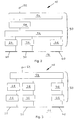
- the probes 20, 30, 40 are also each connected to an evaluation device 50, which will be explained in more detail below with reference to FIGS. 2 and 3.
- the evaluation device 50 evaluates the probe voltages of the probes 20, 30, 40 and generates an output signal 52 as a function of the position of the object 12 relative to the probes 20, 30, 40.
- the reference potential of the voltage source 14 is also earth.
- the coupling capacitor 22 and the capacitor 24 form a capacitive voltage divider with the probe voltage as the center voltage.
- the probe voltages of the various probes 20, 30, 40 are thus dependent on the position of the object 12, with the probe indicating the lowest level to which the object 12 is closest. Since an alternating voltage is applied to the coupling capacitances 22, 32, 42 by the voltage source 14, an alternating voltage, which is processed with the aid of the evaluation device 50, is also applied to the probes 20, 30, 40.
- the arrow 18 indicates in FIG. 1 a displacement of the object 12 within the detection area 16.
- the probe voltage of the probes 20, 30, 40 are each initially directed to a rectifier 26, 36, 46.
- the rectified signals are then fed to a microprocessor 54 via a multiplexer 56 and an analog-to-digital converter 58.
- the microprocessor 54 calculates an output signal from the digitized signals as a function of the position of the object 12 and outputs this signal to the output 52.
- this example can be dispensed with a variety of expensive analog-to-digital converters.
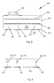
- the coupling capacitances 22, 32, 42 of the device 10 shown in FIG. 1 may, in principle, be designed as discrete capacitors 23, 33, 43, as shown schematically in FIG. 9. This variant is particularly useful when the positioning of one or more probes to be changed, for example, to monitor different areas or paths.
- the probes 20, 30, 40 are arranged linearly in a region 16 to be monitored.
- a coupling layer 72 is also formed by the material of the printed circuit board 70 between the coupling electrode 80 and the probes 20, 30, 40, which increases the coupling capacitances 22, 32, 42 due to the dielectric properties of the printed circuit board material.
- the coupling layer 72 may consist of a substance with a determinable dielectric, for example of printed circuit board material, plastic, glass, ceramic, air or of a foam.
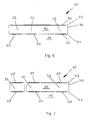
- FIG. 7 differs from the variant according to FIG. 6 essentially in that only the probes 30, 40 are arranged on a common carrier 70, but the probe 20 is arranged on a separate carrier. Furthermore, the variant in FIG. 7 has no continuous coupling electrode, but instead separate coupling electrodes 25, 35, 45 are provided for forming the coupling capacitances 22, 32, 42. Because of the separate foot points, therefore, each coupling capacitance 22, 32, 42 can in principle be supplied with a different AC voltage. For the most common application in which the coupling electrodes 25, 35, 45 form a uniform potential surface, in turn, the connections between the coupling electrodes 25, 35, 45 can be relatively high impedance.
- FIG. 8 A more complex embodiment is finally shown in FIG.
- the probes 20, 30, 40 are again arranged on the outside 71 of the carrier 70 there.
- the coupling electrodes 80 are arranged in the interior of the carrier 70, which may be, for example, a multilayer printed circuit board.
- a further metallic layer 86 is provided, which can optionally serve to shield the probes from the radiation of interference fields.
- an electrical circuit schematically represented by the component 90, is arranged on the side of the carrier 70 opposite the probes 20, 30, 40.
- coupling capacitances 22, 32, 42 are formed by the probes 20, 30, 40 and the coupling electrode 80, which are increased by the dielectric properties of the coupling layer 42.
- the probes 20, 30, 40 In order to detect the movement of an object 12 completely, the probes 20, 30, 40 must be arranged relative to one another such that their sensitivity curves at least partially overlap.
- the probe voltage of a total of three probes 20, 30, 40 which are arranged approximately as shown schematically in Figures 1 to 3.
- the minimum value of the probe voltage of the probe 20 is achieved when probe 20 and object 12 are exactly opposite one another. If the object 12 moves in the direction of the probe 30, the voltage at the probe 20 again increases and the voltage at the probe 30 becomes correspondingly smaller.
Landscapes
- Engineering & Computer Science (AREA)
- Power Engineering (AREA)
- Physics & Mathematics (AREA)
- General Physics & Mathematics (AREA)
- Measurement Of Length, Angles, Or The Like Using Electric Or Magnetic Means (AREA)
- Electronic Switches (AREA)
Applications Claiming Priority (2)
| Application Number | Priority Date | Filing Date | Title |
|---|---|---|---|
| DE102004018630A DE102004018630A1 (de) | 2004-04-16 | 2004-04-16 | Vorrichtung, Sensoranordnung und Verfahren zur kapazitiven Positionserfassung eines Zielobjekts |
| PCT/EP2005/003389 WO2005100924A1 (de) | 2004-04-16 | 2005-03-31 | Vorrichtung, sensoranordnung und verfahren zur kapazitiven positionserfassung eines zielobjekts |
Publications (2)
| Publication Number | Publication Date |
|---|---|
| EP1735595A1 EP1735595A1 (de) | 2006-12-27 |
| EP1735595B1 true EP1735595B1 (de) | 2008-01-09 |
Family
ID=34965848
Family Applications (1)
| Application Number | Title | Priority Date | Filing Date |
|---|---|---|---|
| EP05716480A Expired - Lifetime EP1735595B1 (de) | 2004-04-16 | 2005-03-31 | Vorrichtung, sensoranordnung und verfahren zur kapazitiven positionserfassung eines zielobjekts |
Country Status (6)
| Country | Link |
|---|---|
| US (1) | US20070205775A1 (enExample) |
| EP (1) | EP1735595B1 (enExample) |
| JP (1) | JP2007533220A (enExample) |
| AT (1) | ATE383567T1 (enExample) |
| DE (2) | DE102004018630A1 (enExample) |
| WO (1) | WO2005100924A1 (enExample) |
Families Citing this family (13)
| Publication number | Priority date | Publication date | Assignee | Title |
|---|---|---|---|---|
| US7905488B2 (en) * | 2007-02-19 | 2011-03-15 | Fulgham Jake A | Target game |
| FR2921958B1 (fr) * | 2007-10-03 | 2011-12-02 | Valeo Securite Habitacle | Dispositif de detection de presence d'un utilisateur par un vehicule |
| US8207729B2 (en) | 2009-02-17 | 2012-06-26 | Goodrich Corporation | Non-contact sensor system and method for displacement determination |
| US8164326B2 (en) * | 2009-02-17 | 2012-04-24 | Goodrich Corporation | Non-contact sensor system and method for velocity determination |
| US8203331B2 (en) * | 2009-02-17 | 2012-06-19 | Goodrich Corporation | Non-contact sensor system and method for selection determination |
| US8405386B2 (en) * | 2009-02-17 | 2013-03-26 | Goodrich Corporation | Non-contact sensor system and method for position determination |
| JP5471707B2 (ja) | 2010-03-29 | 2014-04-16 | 富士通株式会社 | 基地局装置及びマルチキャスト信号の配信方法 |
| SE538226C2 (sv) * | 2010-06-07 | 2016-04-12 | Lars Åke Wern | Kapacitivt sensorsystem |
| SE538227C2 (sv) * | 2010-06-07 | 2016-04-12 | Lars Åke Wern | Kapacitivt sensorsystem |
| DE102010031034A1 (de) * | 2010-07-07 | 2012-01-12 | Robert Bosch Gmbh | Erfassung eines dielektrischen Gegenstandes |
| EP3361978B1 (en) | 2015-10-16 | 2025-07-02 | Dalhousie University | Systems for monitoring patient motion via capacitive position sensing |
| DE102016206905B4 (de) | 2016-04-22 | 2025-01-30 | Festo Se & Co. Kg | Linearantriebssystem und Verfahren zur Ermittlung von zwei Positionen zweier Messelemente, die längs eines Bewegungswegs eines Linearantriebssystems bewegt werden |
| DE102016206904A1 (de) * | 2016-04-22 | 2017-10-26 | Festo Ag & Co. Kg | Verfahren zur Ermittlung und Speicherung einer Position eines Messelements längs eines Bewegungswegs und Sensorsystem |
Family Cites Families (25)
| Publication number | Priority date | Publication date | Assignee | Title |
|---|---|---|---|---|
| US3901079A (en) * | 1974-06-18 | 1975-08-26 | Agridustrial Electronics | Two-mode capacitive liquid level sensing system |
| US4071820A (en) * | 1976-04-05 | 1978-01-31 | Alton Corporation | Measurement system |
| JPS5363582A (en) * | 1976-11-18 | 1978-06-07 | Mitsubishi Electric Corp | Proximity detector |
| DE2830432C2 (de) * | 1978-07-11 | 1982-04-22 | Jürgen Ing.(grad.) 8019 Ebersberg Machate | Meßvorrichtung für Längen- oder Winkelmessung |
| US4290052A (en) * | 1979-10-26 | 1981-09-15 | General Electric Company | Capacitive touch entry apparatus having high degree of personal safety |
| JPS57148262A (en) * | 1981-03-09 | 1982-09-13 | Nippon Soken Inc | Detecting device for rotating direction |
| US5049878A (en) * | 1981-05-13 | 1991-09-17 | Drexelbrook Engineering Company | Two-wire compensated level measuring instrument |
| US4706203A (en) * | 1984-12-17 | 1987-11-10 | Simmonds Precision Products, Inc. | Capacitive gauging method and apparatus |
| US4860232A (en) * | 1987-04-22 | 1989-08-22 | Massachusetts Institute Of Technology | Digital technique for precise measurement of variable capacitance |
| GB8718606D0 (en) * | 1987-08-06 | 1987-09-09 | Hiltcroft Packaging Systems Lt | Monitoring apparatus |
| DE3740544C2 (de) * | 1987-11-30 | 1999-08-12 | Neutron Mikroelektronik Gmbh | Einrichtung zur Wandlung einer Weg- oder Winkelgröße in eine elektrische inkrementale oder digitale Größe |
| US5136286A (en) * | 1990-01-29 | 1992-08-04 | Siecor Corporation | Switched capacitance meter reading device using variable width electrodes |
| DE4100556A1 (de) * | 1991-01-10 | 1992-07-16 | Diehl Gmbh & Co | Abfrageschaltung fuer einen kapazitiven positionsgeber |
| US5543588A (en) * | 1992-06-08 | 1996-08-06 | Synaptics, Incorporated | Touch pad driven handheld computing device |
| DE69324067T2 (de) * | 1992-06-08 | 1999-07-15 | Synaptics Inc | Objekt-Positionsdetektor |
| US5463388A (en) * | 1993-01-29 | 1995-10-31 | At&T Ipm Corp. | Computer mouse or keyboard input device utilizing capacitive sensors |
| GB2286247A (en) * | 1994-02-03 | 1995-08-09 | Massachusetts Inst Technology | Capacitive position detection |
| DE19623969B4 (de) * | 1996-06-15 | 2007-04-19 | Werner Turck Gmbh & Co. Kg | Näherungsschalter |
| DE19729347A1 (de) * | 1997-07-09 | 1999-01-14 | Franz Gleixner | Kapazitive Meßvorrichtung für Winkel oder Wege |
| DE19851213C1 (de) * | 1998-11-06 | 2000-06-08 | Daimler Chrysler Ag | Kapazitive Sensoranordnung für ein als Dielektrikum wirkendes flüssiges oder gasförmiges Medium |
| US7030860B1 (en) * | 1999-10-08 | 2006-04-18 | Synaptics Incorporated | Flexible transparent touch sensing system for electronic devices |
| EP1301800B1 (en) * | 2000-05-26 | 2006-08-09 | Automotive Systems Laboratory Inc. | Occupant sensor |
| US6724324B1 (en) * | 2000-08-21 | 2004-04-20 | Delphi Technologies, Inc. | Capacitive proximity sensor |
| DE10204453A1 (de) * | 2001-10-22 | 2003-05-08 | Siemens Ag | Induktiver Wegaufnehmer |
| US20080047764A1 (en) * | 2006-08-28 | 2008-02-28 | Cypress Semiconductor Corporation | Temperature compensation method for capacitive sensors |
-
2004
- 2004-04-16 DE DE102004018630A patent/DE102004018630A1/de not_active Ceased
-
2005
- 2005-03-31 EP EP05716480A patent/EP1735595B1/de not_active Expired - Lifetime
- 2005-03-31 DE DE502005002502T patent/DE502005002502D1/de not_active Expired - Lifetime
- 2005-03-31 US US10/599,879 patent/US20070205775A1/en not_active Abandoned
- 2005-03-31 WO PCT/EP2005/003389 patent/WO2005100924A1/de not_active Ceased
- 2005-03-31 JP JP2007507692A patent/JP2007533220A/ja active Pending
- 2005-03-31 AT AT05716480T patent/ATE383567T1/de not_active IP Right Cessation
Also Published As
| Publication number | Publication date |
|---|---|
| US20070205775A1 (en) | 2007-09-06 |
| JP2007533220A (ja) | 2007-11-15 |
| ATE383567T1 (de) | 2008-01-15 |
| DE102004018630A1 (de) | 2005-11-10 |
| EP1735595A1 (de) | 2006-12-27 |
| DE502005002502D1 (de) | 2008-02-21 |
| WO2005100924A1 (de) | 2005-10-27 |
Similar Documents
| Publication | Publication Date | Title |
|---|---|---|
| EP1735595B1 (de) | Vorrichtung, sensoranordnung und verfahren zur kapazitiven positionserfassung eines zielobjekts | |
| EP2567265B1 (de) | Erfassung eines metallischen oder magnetischen objekts | |
| EP0130940B1 (de) | Induktive Sensoranordnung und Messanordnung zur Verwendung derselben | |
| EP1204848B1 (de) | Verfahren zur füllstandsmessung und füllstandssensor | |
| EP0576714B1 (de) | Vorrichtung zur Messung einer Schichtdicke | |
| DE4317285C2 (de) | Kapazitive Meßsonde für die berührungslose Abstastung von Werkstückoberflächen | |
| DE19610844A1 (de) | Verfahren und System zum Messen von physikalischen Parametern eines Werkstückes | |
| EP2494382B1 (de) | Vorrichtung und verfahren zur fehlerfreien kapazitiven messwerterfassung | |
| EP2707734B1 (de) | Kontaktloser kapazitiver abstandssensor | |
| EP2400275A1 (de) | Berührungslose Füllstandsmessung von Flüssigkeiten | |
| DE10335133A1 (de) | Vorrichtung und Verfahren zur Erfassung des Wegs eines Zielobjektes | |
| WO2009071375A1 (de) | Sensor zur tiefenselektiven ortung dielektrischer werkstoffe und verfahren zum betrieb eines derartigen sensor | |
| DE19806290C2 (de) | Integrierte Entfernungsmeßschaltung | |
| DE102016115483A1 (de) | Verfahren zum Betreiben eines magnetisch-induktiven Durchflussmessgeräts und magnetisch-induktives Durchflussmessgerät | |
| DE19939159A1 (de) | Berührungsempfindliches kapazitives Sensormatrixfeld | |
| EP3246671B1 (de) | Kapazitiver sensor und verfahren zur bestimmung der permittivitätsverteilung in einem objekt | |
| EP4147011A1 (de) | Magnetisch-induktive durchflussmessvorrichtung und verfahren zum ermitteln eines füllstandes | |
| DD297509A5 (de) | Kapazitiver sensor zur beruehrungslosen rauheitsmessung | |
| EP3764054B1 (de) | Sensoranordnung zum erfassen einer auslenkung einer drahtelektrode | |
| DE10063557A1 (de) | Verfahren und Vorrichtung zum Messen von Pegelständen | |
| DE19537059C2 (de) | Anordnung zum berührungslosen Messen der spezifischen Leitfähigkeit wäßriger Lösungen | |
| DE10050193A1 (de) | Sensoranordnung | |
| DE19949612C2 (de) | Kapazitiv messender Sensor und Anordnung | |
| DE102012005708A1 (de) | Schaltvorrichtung mit mindestens zwei Sensoreinrichtungen, Kraftfahrzeug mit der Schaltvorrichtung sowie Verfahren zum Erzeugen eines Schaltsignals unter Verwendung der Schaltvorrichtung | |
| WO2004008084A1 (de) | Verfahren zur messung des füllstandes eines fluids in einem behälter und entsprechender füllstandssensor mit wenigstens einem kapazitiven sensorelement |
Legal Events
| Date | Code | Title | Description |
|---|---|---|---|
| PUAI | Public reference made under article 153(3) epc to a published international application that has entered the european phase |
Free format text: ORIGINAL CODE: 0009012 |
|
| 17P | Request for examination filed |
Effective date: 20060728 |
|
| AK | Designated contracting states |
Kind code of ref document: A1 Designated state(s): AT BE BG CH CY CZ DE DK EE ES FI FR GB GR HU IE IS IT LI LT LU MC NL PL PT RO SE SI SK TR |
|
| RIN1 | Information on inventor provided before grant (corrected) |
Inventor name: EHRENFRIED, ULRICH Inventor name: VOELKEL, HARDI |
|
| DAX | Request for extension of the european patent (deleted) | ||
| GRAP | Despatch of communication of intention to grant a patent |
Free format text: ORIGINAL CODE: EPIDOSNIGR1 |
|
| GRAS | Grant fee paid |
Free format text: ORIGINAL CODE: EPIDOSNIGR3 |
|
| GRAA | (expected) grant |
Free format text: ORIGINAL CODE: 0009210 |
|
| AK | Designated contracting states |
Kind code of ref document: B1 Designated state(s): AT BE BG CH CY CZ DE DK EE ES FI FR GB GR HU IE IS IT LI LT LU MC NL PL PT RO SE SI SK TR |
|
| REG | Reference to a national code |
Ref country code: GB Ref legal event code: FG4D Free format text: NOT ENGLISH |
|
| REG | Reference to a national code |
Ref country code: CH Ref legal event code: EP |
|
| REG | Reference to a national code |
Ref country code: IE Ref legal event code: FG4D Free format text: LANGUAGE OF EP DOCUMENT: GERMAN |
|
| GBT | Gb: translation of ep patent filed (gb section 77(6)(a)/1977) |
Effective date: 20080123 |
|
| REG | Reference to a national code |
Ref country code: CH Ref legal event code: NV Representative=s name: BOGENSBERGER PATENT- & MARKENBUERO DR. BURKHARD BO |
|
| REF | Corresponds to: |
Ref document number: 502005002502 Country of ref document: DE Date of ref document: 20080221 Kind code of ref document: P |
|
| PG25 | Lapsed in a contracting state [announced via postgrant information from national office to epo] |
Ref country code: NL Free format text: LAPSE BECAUSE OF FAILURE TO SUBMIT A TRANSLATION OF THE DESCRIPTION OR TO PAY THE FEE WITHIN THE PRESCRIBED TIME-LIMIT Effective date: 20080109 Ref country code: SI Free format text: LAPSE BECAUSE OF FAILURE TO SUBMIT A TRANSLATION OF THE DESCRIPTION OR TO PAY THE FEE WITHIN THE PRESCRIBED TIME-LIMIT Effective date: 20080109 |
|
| NLV1 | Nl: lapsed or annulled due to failure to fulfill the requirements of art. 29p and 29m of the patents act | ||
| PG25 | Lapsed in a contracting state [announced via postgrant information from national office to epo] |
Ref country code: LT Free format text: LAPSE BECAUSE OF FAILURE TO SUBMIT A TRANSLATION OF THE DESCRIPTION OR TO PAY THE FEE WITHIN THE PRESCRIBED TIME-LIMIT Effective date: 20080109 Ref country code: ES Free format text: LAPSE BECAUSE OF FAILURE TO SUBMIT A TRANSLATION OF THE DESCRIPTION OR TO PAY THE FEE WITHIN THE PRESCRIBED TIME-LIMIT Effective date: 20080420 Ref country code: IS Free format text: LAPSE BECAUSE OF FAILURE TO SUBMIT A TRANSLATION OF THE DESCRIPTION OR TO PAY THE FEE WITHIN THE PRESCRIBED TIME-LIMIT Effective date: 20080509 Ref country code: FI Free format text: LAPSE BECAUSE OF FAILURE TO SUBMIT A TRANSLATION OF THE DESCRIPTION OR TO PAY THE FEE WITHIN THE PRESCRIBED TIME-LIMIT Effective date: 20080109 |
|
| REG | Reference to a national code |
Ref country code: CH Ref legal event code: PFA Owner name: PEPPERL + FUCHS GMBH Free format text: PEPPERL + FUCHS GMBH#KOENIGSBERGER ALLEE 87#68307 MANNHEIM (DE) -TRANSFER TO- PEPPERL + FUCHS GMBH#KOENIGSBERGER ALLEE 87#68307 MANNHEIM (DE) |
|
| PG25 | Lapsed in a contracting state [announced via postgrant information from national office to epo] |
Ref country code: BG Free format text: LAPSE BECAUSE OF FAILURE TO SUBMIT A TRANSLATION OF THE DESCRIPTION OR TO PAY THE FEE WITHIN THE PRESCRIBED TIME-LIMIT Effective date: 20080409 |
|
| ET | Fr: translation filed | ||
| BERE | Be: lapsed |
Owner name: PEPPERL + FUCHS G.M.B.H. Effective date: 20080331 |
|
| PG25 | Lapsed in a contracting state [announced via postgrant information from national office to epo] |
Ref country code: PL Free format text: LAPSE BECAUSE OF FAILURE TO SUBMIT A TRANSLATION OF THE DESCRIPTION OR TO PAY THE FEE WITHIN THE PRESCRIBED TIME-LIMIT Effective date: 20080109 Ref country code: PT Free format text: LAPSE BECAUSE OF FAILURE TO SUBMIT A TRANSLATION OF THE DESCRIPTION OR TO PAY THE FEE WITHIN THE PRESCRIBED TIME-LIMIT Effective date: 20080609 |
|
| REG | Reference to a national code |
Ref country code: IE Ref legal event code: FD4D |
|
| PG25 | Lapsed in a contracting state [announced via postgrant information from national office to epo] |
Ref country code: SE Free format text: LAPSE BECAUSE OF FAILURE TO SUBMIT A TRANSLATION OF THE DESCRIPTION OR TO PAY THE FEE WITHIN THE PRESCRIBED TIME-LIMIT Effective date: 20080409 Ref country code: CZ Free format text: LAPSE BECAUSE OF FAILURE TO SUBMIT A TRANSLATION OF THE DESCRIPTION OR TO PAY THE FEE WITHIN THE PRESCRIBED TIME-LIMIT Effective date: 20080109 Ref country code: IE Free format text: LAPSE BECAUSE OF FAILURE TO SUBMIT A TRANSLATION OF THE DESCRIPTION OR TO PAY THE FEE WITHIN THE PRESCRIBED TIME-LIMIT Effective date: 20080109 Ref country code: SK Free format text: LAPSE BECAUSE OF FAILURE TO SUBMIT A TRANSLATION OF THE DESCRIPTION OR TO PAY THE FEE WITHIN THE PRESCRIBED TIME-LIMIT Effective date: 20080109 Ref country code: DK Free format text: LAPSE BECAUSE OF FAILURE TO SUBMIT A TRANSLATION OF THE DESCRIPTION OR TO PAY THE FEE WITHIN THE PRESCRIBED TIME-LIMIT Effective date: 20080109 Ref country code: MC Free format text: LAPSE BECAUSE OF NON-PAYMENT OF DUE FEES Effective date: 20080331 |
|
| PLBE | No opposition filed within time limit |
Free format text: ORIGINAL CODE: 0009261 |
|
| STAA | Information on the status of an ep patent application or granted ep patent |
Free format text: STATUS: NO OPPOSITION FILED WITHIN TIME LIMIT |
|
| PG25 | Lapsed in a contracting state [announced via postgrant information from national office to epo] |
Ref country code: RO Free format text: LAPSE BECAUSE OF FAILURE TO SUBMIT A TRANSLATION OF THE DESCRIPTION OR TO PAY THE FEE WITHIN THE PRESCRIBED TIME-LIMIT Effective date: 20080109 |
|
| 26N | No opposition filed |
Effective date: 20081010 |
|
| PG25 | Lapsed in a contracting state [announced via postgrant information from national office to epo] |
Ref country code: EE Free format text: LAPSE BECAUSE OF FAILURE TO SUBMIT A TRANSLATION OF THE DESCRIPTION OR TO PAY THE FEE WITHIN THE PRESCRIBED TIME-LIMIT Effective date: 20080109 |
|
| PG25 | Lapsed in a contracting state [announced via postgrant information from national office to epo] |
Ref country code: BE Free format text: LAPSE BECAUSE OF NON-PAYMENT OF DUE FEES Effective date: 20080331 |
|
| PG25 | Lapsed in a contracting state [announced via postgrant information from national office to epo] |
Ref country code: CY Free format text: LAPSE BECAUSE OF FAILURE TO SUBMIT A TRANSLATION OF THE DESCRIPTION OR TO PAY THE FEE WITHIN THE PRESCRIBED TIME-LIMIT Effective date: 20080109 |
|
| PG25 | Lapsed in a contracting state [announced via postgrant information from national office to epo] |
Ref country code: AT Free format text: LAPSE BECAUSE OF NON-PAYMENT OF DUE FEES Effective date: 20080331 |
|
| PG25 | Lapsed in a contracting state [announced via postgrant information from national office to epo] |
Ref country code: HU Free format text: LAPSE BECAUSE OF FAILURE TO SUBMIT A TRANSLATION OF THE DESCRIPTION OR TO PAY THE FEE WITHIN THE PRESCRIBED TIME-LIMIT Effective date: 20080710 Ref country code: LU Free format text: LAPSE BECAUSE OF NON-PAYMENT OF DUE FEES Effective date: 20080331 |
|
| PG25 | Lapsed in a contracting state [announced via postgrant information from national office to epo] |
Ref country code: TR Free format text: LAPSE BECAUSE OF FAILURE TO SUBMIT A TRANSLATION OF THE DESCRIPTION OR TO PAY THE FEE WITHIN THE PRESCRIBED TIME-LIMIT Effective date: 20080109 |
|
| PG25 | Lapsed in a contracting state [announced via postgrant information from national office to epo] |
Ref country code: GR Free format text: LAPSE BECAUSE OF FAILURE TO SUBMIT A TRANSLATION OF THE DESCRIPTION OR TO PAY THE FEE WITHIN THE PRESCRIBED TIME-LIMIT Effective date: 20080410 |
|
| PGFP | Annual fee paid to national office [announced via postgrant information from national office to epo] |
Ref country code: IT Payment date: 20120328 Year of fee payment: 8 |
|
| REG | Reference to a national code |
Ref country code: CH Ref legal event code: PCAR Free format text: NEW ADDRESS: FALLSGASSE 7, 9492 ESCHEN (LI) |
|
| PG25 | Lapsed in a contracting state [announced via postgrant information from national office to epo] |
Ref country code: IT Free format text: LAPSE BECAUSE OF NON-PAYMENT OF DUE FEES Effective date: 20130331 |
|
| PGFP | Annual fee paid to national office [announced via postgrant information from national office to epo] |
Ref country code: CH Payment date: 20150326 Year of fee payment: 11 |
|
| REG | Reference to a national code |
Ref country code: FR Ref legal event code: PLFP Year of fee payment: 12 |
|
| PGFP | Annual fee paid to national office [announced via postgrant information from national office to epo] |
Ref country code: FR Payment date: 20160330 Year of fee payment: 12 Ref country code: GB Payment date: 20160303 Year of fee payment: 12 |
|
| REG | Reference to a national code |
Ref country code: CH Ref legal event code: PL |
|
| PG25 | Lapsed in a contracting state [announced via postgrant information from national office to epo] |
Ref country code: CH Free format text: LAPSE BECAUSE OF NON-PAYMENT OF DUE FEES Effective date: 20160331 Ref country code: LI Free format text: LAPSE BECAUSE OF NON-PAYMENT OF DUE FEES Effective date: 20160331 |
|
| GBPC | Gb: european patent ceased through non-payment of renewal fee |
Effective date: 20170331 |
|
| REG | Reference to a national code |
Ref country code: FR Ref legal event code: ST Effective date: 20171130 |
|
| PG25 | Lapsed in a contracting state [announced via postgrant information from national office to epo] |
Ref country code: FR Free format text: LAPSE BECAUSE OF NON-PAYMENT OF DUE FEES Effective date: 20170331 |
|
| PG25 | Lapsed in a contracting state [announced via postgrant information from national office to epo] |
Ref country code: GB Free format text: LAPSE BECAUSE OF NON-PAYMENT OF DUE FEES Effective date: 20170331 |
|
| REG | Reference to a national code |
Ref country code: DE Ref legal event code: R082 Ref document number: 502005002502 Country of ref document: DE Representative=s name: SCHIFFER, AXEL, DIPL.-PHYS.UNIV. DR.RER.NAT., DE |
|
| PGFP | Annual fee paid to national office [announced via postgrant information from national office to epo] |
Ref country code: DE Payment date: 20240321 Year of fee payment: 20 |
|
| REG | Reference to a national code |
Ref country code: DE Ref legal event code: R071 Ref document number: 502005002502 Country of ref document: DE |