EP1734320A2 - Verfahren und Vorrichtung zum kontinuierlichen Kühlen eines pumpfähigen Materials mit einer kryogenen Flüssigkeit - Google Patents
Verfahren und Vorrichtung zum kontinuierlichen Kühlen eines pumpfähigen Materials mit einer kryogenen Flüssigkeit Download PDFInfo
- Publication number
- EP1734320A2 EP1734320A2 EP06011959A EP06011959A EP1734320A2 EP 1734320 A2 EP1734320 A2 EP 1734320A2 EP 06011959 A EP06011959 A EP 06011959A EP 06011959 A EP06011959 A EP 06011959A EP 1734320 A2 EP1734320 A2 EP 1734320A2
- Authority
- EP
- European Patent Office
- Prior art keywords
- liquid
- mixer
- continuous mechanical
- cryogen
- mechanical mixer
- Prior art date
- Legal status (The legal status is an assumption and is not a legal conclusion. Google has not performed a legal analysis and makes no representation as to the accuracy of the status listed.)
- Withdrawn
Links
Images
Classifications
-
- F—MECHANICAL ENGINEERING; LIGHTING; HEATING; WEAPONS; BLASTING
- F28—HEAT EXCHANGE IN GENERAL
- F28D—HEAT-EXCHANGE APPARATUS, NOT PROVIDED FOR IN ANOTHER SUBCLASS, IN WHICH THE HEAT-EXCHANGE MEDIA DO NOT COME INTO DIRECT CONTACT
- F28D7/00—Heat-exchange apparatus having stationary tubular conduit assemblies for both heat-exchange media, the media being in contact with different sides of a conduit wall
-
- A—HUMAN NECESSITIES
- A23—FOODS OR FOODSTUFFS; TREATMENT THEREOF, NOT COVERED BY OTHER CLASSES
- A23D—EDIBLE OILS OR FATS, e.g. MARGARINES, SHORTENINGS, COOKING OILS
- A23D7/00—Edible oil or fat compositions containing an aqueous phase, e.g. margarines
- A23D7/02—Edible oil or fat compositions containing an aqueous phase, e.g. margarines characterised by the production or working-up
- A23D7/04—Working-up
- A23D7/05—Working-up characterised by essential cooling
-
- F—MECHANICAL ENGINEERING; LIGHTING; HEATING; WEAPONS; BLASTING
- F25—REFRIGERATION OR COOLING; COMBINED HEATING AND REFRIGERATION SYSTEMS; HEAT PUMP SYSTEMS; MANUFACTURE OR STORAGE OF ICE; LIQUEFACTION SOLIDIFICATION OF GASES
- F25D—REFRIGERATORS; COLD ROOMS; ICE-BOXES; COOLING OR FREEZING APPARATUS NOT OTHERWISE PROVIDED FOR
- F25D3/00—Devices using other cold materials; Devices using cold-storage bodies
- F25D3/10—Devices using other cold materials; Devices using cold-storage bodies using liquefied gases, e.g. liquid air
- F25D3/11—Devices using other cold materials; Devices using cold-storage bodies using liquefied gases, e.g. liquid air with conveyors carrying articles to be cooled through the cooling space
-
- F—MECHANICAL ENGINEERING; LIGHTING; HEATING; WEAPONS; BLASTING
- F28—HEAT EXCHANGE IN GENERAL
- F28D—HEAT-EXCHANGE APPARATUS, NOT PROVIDED FOR IN ANOTHER SUBCLASS, IN WHICH THE HEAT-EXCHANGE MEDIA DO NOT COME INTO DIRECT CONTACT
- F28D1/00—Heat-exchange apparatus having stationary conduit assemblies for one heat-exchange medium only, the media being in contact with different sides of the conduit wall, in which the other heat-exchange medium is a large body of fluid, e.g. domestic or motor car radiators
-
- F—MECHANICAL ENGINEERING; LIGHTING; HEATING; WEAPONS; BLASTING
- F25—REFRIGERATION OR COOLING; COMBINED HEATING AND REFRIGERATION SYSTEMS; HEAT PUMP SYSTEMS; MANUFACTURE OR STORAGE OF ICE; LIQUEFACTION SOLIDIFICATION OF GASES
- F25D—REFRIGERATORS; COLD ROOMS; ICE-BOXES; COOLING OR FREEZING APPARATUS NOT OTHERWISE PROVIDED FOR
- F25D2400/00—General features of, or devices for refrigerators, cold rooms, ice-boxes, or for cooling or freezing apparatus not covered by any other subclass
- F25D2400/02—Refrigerators including a heater
-
- F—MECHANICAL ENGINEERING; LIGHTING; HEATING; WEAPONS; BLASTING
- F25—REFRIGERATION OR COOLING; COMBINED HEATING AND REFRIGERATION SYSTEMS; HEAT PUMP SYSTEMS; MANUFACTURE OR STORAGE OF ICE; LIQUEFACTION SOLIDIFICATION OF GASES
- F25D—REFRIGERATORS; COLD ROOMS; ICE-BOXES; COOLING OR FREEZING APPARATUS NOT OTHERWISE PROVIDED FOR
- F25D2700/00—Means for sensing or measuring; Sensors therefor
- F25D2700/16—Sensors measuring the temperature of products
Definitions
- Cooling may be effected by indirect heat exchange with cooling water, refrigerants, or cold process streams in various types of indirect heat exchangers including shell-and-tube, scraped surface, tube-in-tube, coil-in-kettle, and multi-plate.
- cooling may be effected by direct contact of the pumpable materials with coolants such as chilled water, cold gas, or vaporizing cryogenic liquids.
- the cooling of pumpable materials may be carried out in batch or continuous processes.
- rapid cooling is required to minimize the cooling time in a temperature range conducive to the growth of undesirable bacteria.
- the application of vaporizing cryogenic liquids in the prepared food industry is advantageous for the rapid cooling of warm intermediate materials and/or final prepared food products.
- the cooling of pumpable materials with vaporizing cryogenic liquids may be carried out in mixed batch processes or in continuous processes using static inline mixers.
- An embodiment of the invention relates to a system for cooling a pumpable material comprising (a) an inline continuous mechanical mixer having a feed inlet, a liquid cryogen inlet, and a cooled product outlet; (b) a cryogenic liquid delivery and injection system adapted to introduce a liquid cryogen into the liquid cryogen inlet; and (c) a feed system adapted to introduce the pumpable material into the feed inlet.
- the system may further comprise a product receiver connected to the cooled product outlet and adapted to disengage vaporized cryogen from cooled product to provide a final cooled product and vaporized cryogen.
- the inline continuous mechanical mixer may be selected from the group consisting of paddle, single rotor, multi-rotor, pin, medium shear, high shear, axial flow, cross flow, propeller, scraped surface, and turbine mixers.
- the inline continuous mechanical mixer is driven by an electric motor; the power rating of the electric motor and the internal volume of the inline continuous mechanical mixer may be characterized by a power to volume ratio in the range of 0.3 to 2.0 kW per liter of internal volume of the inline continuous mechanical mixer.
- the liquid cryogen inlet typically is located adjacent the feed inlet.
- the system may further include at least one additional liquid cryogen inlet disposed between the feed inlet and the intermediate cooled product outlet.
- the cryogenic liquid storage and injection system typically is adapted to store and inject a liquid cryogen selected from the group consisting of liquid nitrogen, liquid carbon dioxide, liquid argon, and liquid air.
- the liquid cryogen inlet may include a nozzle and a heating system to heat the nozzle.
- the inline continuous mechanical mixer typically includes a vessel with walls having an inner surface and an outer surface and may include a mixer heating system adapted to heat the inner surface; in this case, the liquid cryogen inlet may comprise a nozzle and a nozzle heating system to heat the nozzle.
- the mixer heating system may be selected from the group consisting of a recirculating hot water jacket in contact with the outer surface of the vessel, steam tracing on the outer surface of the vessel, and electric resistance heaters on the outer surface of the vessel.
- the nozzle may comprise a heat conductive metal selected from copper, brass, bronze, aluminum, and combinations of these metals, wherein the heat conductive metal is in thermal contact with the mixer heating system, or the inner surface of the vessel, or the mixer heating system and the inner surface of the vessel.
- This embodiment may further comprise an additional inline continuous mechanical mixer having a intermediate feed inlet and a secondary cooled product outlet, wherein intermediate cooled product outlet of the inline continuous mechanical mixer of (a) is connected to the intermediate feed inlet of the additional inline continuous mechanical mixer.
- the additional inline continuous mechanical mixer may have a liquid cryogen inlet adjacent the intermediate feed inlet and connected to the cryogenic liquid storage and injection system of (b).
- This embodiment may further comprise providing a product receiver connected to the cooled product outlet, introducing the cooled product into the product receiver, disengaging vaporized cryogen from the intermediate cooled product, and withdrawing from the product receiver a final cooled product and vaporized cryogen.
- the liquid cryogen may be selected from the group consisting of liquid nitrogen, liquid carbon dioxide, liquid argon, and liquid air.
- the mass flow ratio of the liquid cryogen to the pumpable material may be in the range of 0.1 to 2.0.
- the inline continuous mechanical mixer may be a paddle mixer, which may be operated at a rotational speed in the range of 400 to 2000 revolutions per minute.
- the residence time of the pumpable material in the inline continuous mechanical mixer may be between 1 and 60 seconds.
- the pumpable material may be selected from the group consisting of an oil-in-water emulsion, a water-in-oil emulsion, a solid-liquid slurry, a paste, a liquid, and a pumpable flowable powder.
- the pumpable material may be selected from the group consisting of mayonnaise, toppings, sauces, soups, milk-containing mixtures, margarine, ice cream, puddings, mousse products, cheese and curd products, pestos, chutneys, and beverages.
- the inline continuous mechanical mixer may be a paddle mixer
- the pumpable material may be mayonnaise
- the liquid cryogen may be liquid nitrogen.
- the paddle mixer may be operated at a rotational speed in the range of 500 to 900 revolutions per minute.
- the inline continuous mechanical mixer typically includes a vessel with walls having an inner surface and an outer surface and includes a mixer heating system adapted to heat the inner surface while mixing the liquid cryogen and the pumpable material during passage through the inline continuous mechanical mixer, thereby preventing freezing of the pumpable material on the inner surface of the inline continuous mechanical mixer.
- the liquid cryogen inlet may include a nozzle and a nozzle heating system to heat the nozzle while introducing the liquid cryogen into the inline continuous mechanical mixer via the liquid cryogen inlet, thereby preventing freezing of the pumpable material on the nozzle.
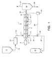
- Fig. 1 is a schematic flow diagram of an embodiment of the present invention.
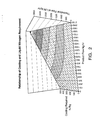
- Fig. 2 illustrates an exemplary relationship among liquid nitrogen flow, product flow, and cooling requirement for a given liquid nitrogen calorific value according to an embodiment of the invention.
- the embodiments of the present invention relate to a continuous process for the rapid cooling of a pumpable material by mixing the material with a vaporizing cryogenic liquid or cryogen while the material and cryogen flow through an inline continuous mechanical mixer.
- the cooling is characterized by direct heat transfer from the pumpable material to the cryogen wherein heat is absorbed by the latent heat of vaporization of the cryogen and the sensible heat of the warming vapor.
- the discharge from the inline continuous mechanical mixer may flow into a product receiver to disengage and exhaust vaporized cryogen from the intermediate cooled product to provide a final cooled product and vaporized cryogen.
- some residual gas may remain in the cooled material if desired to provide a light gas-filled, whipped, or moussed product.
- cooling is defined as the removal of heat from the pumpable material wherein the heat removed may be sensible heat, latent heat, or both sensible heat and latent heat of components in the pumpable material. Components in the pumpable material may change from the liquid to the solid phase under appropriate cooling conditions.
- a wide range of materials may be processed using the embodiments of the invention as long as the material can be pumped through the inline continuous mechanical mixer, i.e., as long as each material is a pumpable material.
- These pumpable materials may include, for example, prepared foods, confections, pharmaceuticals, health care products, cosmetics, specialty chemicals, and other high-value products which require rapid direct cooling in the manufacturing process.
- the pumpable material may be, for example, an oil-in-water emulsion, a water-in-oil emulsion, a solid-liquid slurry, a paste, a liquid, or a pumpable flowable powder.
- Food products that can be cooled advantageously by the process may include, for example, mayonnaise, toppings, sauces, soups, milk-containing mixtures, margarine, ice cream, puddings, mousse products, cheese and curd products, pestos, chutneys, and beverages.
- Any pumpable food product or intermediate material may be cooled using the embodiments described herein.
- the cooling process may be used to freeze or partially freeze material to make pumpable products such as frozen confections, flavored ices, frozen toppings, and the like.
- the term "pumpable material” is defined as any material that can be caused to flow through an inline continuous mechanical mixer.
- the pressure driving force required to force the material to flow through the mixer may be provided by any known pressurizing device.
- This device may be any type of positive displacement pump known in the art, for example, a progressive cavity, piston, gear, lobe, signe, diaphragm, peristaltic, or screw pump.
- the pressurizing device may provide the pressure driving force by gravity, pressurized gas, or pressurized liquid.
- feed system is defined herein as apparatus adapted to introduce the pumpable material into the inline continuous mechanical mixer including, but not limited to, a pressurizing device to provide the pressure driving force described above and piping from the pressurizing device to the inline continuous mechanical mixer.
- inline continuous mechanical mixer is defined as a vessel having an inlet and an outlet wherein one or more mechanical mixing devices are disposed within the mixing vessel between the inlet and outlet and are adapted to mix the pumpable material as it passes through the vessel.
- a mechanical mixing device is a rotating or moving element that promotes physical mechanical mixing of the pumpable material as it moves through the vessel. Rotating or moving elements may include, for example, paddles, pins, scrapers, propellers, turbines, or other devices that shear the pumpable material to cause mixing.
- Exemplary types of inline continuous mechanical mixers may include, for example, an axial-flow tubular vessel having a coaxial shaft that passes through the vessel and is fitted with shear-inducing elements such as radial paddles, pins, or scrapers. The shaft is rotated to induce mixing of the pumpable material as it flows through the tubular vessel.
- a liquid cryogen is defined as any liquid that has a boiling point below ambient temperature and particularly below about -40°C.
- liquid cryogen liquid cryogen
- the walls may be heated by any appropriate means such as, for example, a recirculating hot water jacket in contact with the outer surface of the mixer vessel, steam tracing on the outer surface of the vessel, and/or electric resistance heaters on the outer surface of the vessel.
- Exemplary inline continuous mechanical mixer 1 comprises tubular vessel 3, coaxial mixer shaft 5, paddles or mixing elements 7, electric drive motor 9, pumpable material inlet 11, cryogen inlet 13, and cooled pumpable material outlet 15.
- the power rating of the electric motor and the internal volume of the inline continuous mechanical mixer may be characterized by a power to volume ratio in the range of 0.3 to 2.0 kW per liter of internal volume of the inline continuous mechanical mixer.
- the feed material to be cooled may be stored as needed in feed vessel 17, flows via line 19 to pump 21, and is pumped via line 23 to pumpable material inlet 11.
- Liquid cryogen is stored in insulated cryogen storage tank or dewar 25 and flows via line 27, flow control valve 29, and line 31 to cryogen inlet 13.
- Cryogen injector nozzle 14 may be used to inject cryogen into the feed material, and radially-oriented multiple nozzles may be used if desired. Any type of insulated liquid cryogen storage and piping system may be used as is known in the art.
- the feed material may flow by gravity through lines 19 and 23 when sufficient head is provided between feed vessel 17 and inline continuous mechanical mixer 1. Additionally or alternatively, the feed material may be pressurized by a gas or liquid in the head space of feed vessel 17 and the pressurized feed directed to flow through lines 19 and 23.
- Cooled pumpable material exits the mixer via outlet 15 and line 33 and may flow to product receiver 35, where vaporized cryogen, water, and entrained product (if present) may be disengaged from the cooled material as required.
- the cooled material may flow directly from cooled pumpable material outlet 15 to a product packaging step (not shown).
- Cryogen vapor is discharged via line 37 and the final cooled product is withdrawn via line 39.
- the flow rate of the cryogen may be controlled manually via flow control valve 29.
- the cryogen flow may be controlled by measuring the temperature of the cooled material by temperature element 41 and using this measured temperature to control the cryogen flow rate by controller 43 via control signal line 45.
- Other cryogen flow control methods are possible.
- the temperature of the feed material in line 23 can be measured and utilized for feedforward control of the cryogen flow by flow control valve 29.
- Fig. 1 Process variations of the system of Fig. 1 are possible to increase operating efficiency or throughput.
- multiple cryogen injection points may be used along tubular vessel 3.
- two or more inline continuous mechanical mixers may be arranged in series and/or in parallel.
- the tubular mixer may be mounted horizontally, vertically, or at any angle as desired for optimum performance.
- additional ingredients may be introduced via another inlet (not shown) at or near the inlet of tubular vessel 3.
- additional ingredients could include, for example, herbs, flavorings, diced onions, and the like.
- the outer surface of tubular vessel 3 may be heated by any appropriate means (not shown) in order to heat to the inner surface of the vessel to prevent freezing and sticking of the pumpable material on this surface.
- Heating means may include, for example, a recirculating hot water jacket in contact with the outer surface of the vessel, steam tracing on the outer surface of the vessel, and/or electric resistance heaters on the outer surface of the vessel.
- Cryogen injector nozzle 14 also may be heated to prevent freezing and sticking of the pumpable material to the inner and/or outer surfaces of the nozzle.
- the nozzle at least in part from a heat-conductive metal such as copper, brass, bronze, aluminum, or combinations thereof, wherein the heat-conductive metal is in thermal contact with either of or both of the mixer vessel heating system and the inner surface of the vessel.
- the surface of the nozzle in contact with the pumpable product may be fabricated of stainless steel, for example, if the pumpable material is a food, pharmaceutical, or corrosive product.
- Generic types of continuous mixers may include, for example, paddle, single rotor, multi-rotor, pin, medium shear, high shear, axial flow, cross flow, propeller, scraped surface, and turbine mixers.
- Exemplary commercially-available inline continuous mechanical mixers that may be adapted for use in the system illustrated in Fig. 1 include various models of the axial paddle mixer sold by AEROMIX Gmbh in Germany.
- a scraped surface mixer may be a scraped surface heat exchanger selected from, for example, the Votator ® line of scraped-surface heat exchangers sold by Waukesha Cherry-Burrell of Delavan, WI, USA, Contherm ® and ViscoLine exchangers sold by Alfa Laval, the Thermorotor exchanger sold by GMF-Gouda in the Netherlands, the Schroeder Kombinator in Germany, and the scraped surface heat exchangers sold by APV/Invensys.
- the outer wall would be heated rather than cooled; the heating may be provided by any appropriate means such as, for example, a recirculating hot water jacket, steam tracing, and/or electric resistance heaters on the outer surface of the vessel.
- Controllable process variables include, for example, the amount of liquid cryogen supplied per unit amount of pumpable material processed, the degree of mixing (for example, the rotational speed of a paddle mixer) and the amount of mixing energy provided per unit amount of pumpable material processed, the residence time of the pumpable material in the inline continuous mechanical mixer, the temperatures of the heated mixer walls and the cryogen inlet nozzle, and the properties of the cryogen.
- Typical operating parameter ranges may include, for example, a mass flow ratio of the liquid cryogen to the pumpable material in the range of 0.1 to 2.0; a paddle mixer rotational speed in the range of 400 to 2000 revolutions per minute; a residence time of the pumpable material in the inline continuous mechanical mixer between about 1 and about 60 seconds; and specific power consumption of the electric motor driving the inline mixer in the range of 0.3 to 2.0 kW per liter of continuous mechanical mixer internal volume.
- the cryogenically-cooled inline continuous mechanical mixer may be used to introduce gas into the final product by whipping or moussing while cooling takes place.
- the whipped product may be cooled into the freezing range to provide frozen whipped products such as cream, ice cream, and margarine.
- the choice of cryogen may be determined by the required product specifications. For example, nitrogen may be required in certain cases because of its inert and neutral properties.
- carbon dioxide may be used for cooling products wherein the acidic properties and bacterial growth inhibiting properties of carbon dioxide are desirable.
- Liquid nitrogen is an advantageous cryogen for use with the various embodiments of the invention.
- the amount of LIN injection required during system operation is a function of various parameters such as, for example, (1) the purity and latent heat of vaporization of the liquid nitrogen being supplied, (2) the thermal characteristics of the product to be chilled and/or frozen, (3) the final temperature of the chilled/frozen product, (4) the amount or flow rate of the product to be chilled/frozen, and (5) the thermal losses of the process and equipment.
- the calorific value of chilling which can be obtained from LIN is dependent upon the properties of the LIN and the efficiency at which it is used, i.e., the temperature at which the gas is released and the operating characteristics of the equipment supplying and using the LIN. For example, a value of 340kJ/kg may be taken as a typical amount of cold provided by vaporizing LIN including the latent heat of vaporization, sensible heat of the warming vapor, and representative heat losses in the system. If the LIN supply is subcooled and the gas fraction reduced, this value may be increased, for example, to 360kJ/kg.
- All chemical or food products have different rates of chilling and freezing due to the properties of their constituents.
- the amount of refrigeration to chill one liquid from 50°C to 5°C, for example, will usually require a different amount of chilling than another liquid through the same temperature range.
- the actual amount of chilling provided may be expressed in kJ/kg of the product.
- a relatively linear cooling rate usually occurs due to the relatively constant specific heat of the substance. For example, water chills at a specific heat of -4.2kJ/kg per °C until it begins to form ice at 0°C.
- this constant rate of chilling may pass below 0°C due to the freezing point depression of the non-aqueous constituents.
- one type of mayonnaise was observed to have a freezing point of about -5°C with a specific heat of 3.0 kJ/kg above that point. To cool from 30°C to -5°C therefore would require 75kJ/kg of chilling.
- Fig. 2 illustrates one exemplary relationship among LIN flow, product flow, and cooling requirement for a given LIN calorific value.
- Other variables may change the LIN requirement relationships of Fig. 2. These variables may include, for example, thermal losses that change with ambient temperature, the heat of mixing of the specific product being cooled, individual process requirements, and the heat transfer and heat loss properties of specific equipment.
- a pumpable broccoli cream sauce was chilled from 8.2°C to temperatures below 0°C such that the product consistency became pasty and partially frozen, thereby making the chilled sauce suitable for forming sauce pellets.
- the chilling process utilized the system illustrated in Fig. 1.
- Feed vessel 17 was a 900 liter transitank for sauce storage.
- Pump 21 was a 12 stage progressive cavity Seepex pump having a 150 to 1500 m 3 /hr throughput and a 0.98kW drive motor.
- Inline continuous mechanical mixer 1 was a dynamic paddle mixer with a continuously heated outer water jacket.
- the mixer had a 1 ⁇ 4" connection for the inlet of LIN via line 31.
- the mixer barrel diameter was approximately 120 mm and the barrel length was approximately 500 mm.
- Drive motor 9 was rated at 1.1kW.
- the product inlet and outlet connections were DN 40.
- the paddle shaft had a diameter of approximately 15 mm and had five sections of three paddles each.
- RTD temperature probes were installed at the inlet and outlet of the mixer. A liquid flowmeter, temperature probe, and pressure transmitter were installed at the pump outlet (not shown in Fig. 1).
- the mixer was fitted with a 1 ⁇ 4" inlet for gaseous nitrogen (GAN) and 2-off Harsco 600 liter minitanks were provided for GAN and LIN supply at 4 bar supply pressure (GAN supply is not shown in Fig. 1).
- GAN supply is not shown in Fig. 1).
- a 3-way ball valve with actuator (not shown) was provided to select between LIN supply and purging GAN supply.
- the LIN control valve was a Badger valve having a C v of 4.0 and was controlled either by product outlet temperature or set to a fixed opening.
- a Witt thermal relief valve was installed after the control valve.
- a control panel was fitted with a Siemens OP17 HMI, C7634P PLC and inverters for pump and paddle mixer agitator speed control (not shown in Fig, 1).
- the broccoli cream sauce was stored at approximately 8°C in a 900 liter transitank (feed vessel 17) at a depth of approximately 1.5 meters.
- the outlet of the tank was connected to the inlet of pump 21 by line 19, which was a flexible dairy hose, such that the sauce was gravity fed to pump 21.
- the sauce was delivered by the progressive cavity pump to continuous dynamic paddle mixer 1 via line 23, which was fitted with the flowmeter, pressure transmitter, and temperature probe.
- the 1 ⁇ 4" connection situated near the product inlet on the mixer was connected to the UN / GAN valve feed train. Delivery of either LIN (for cooling) or GAN (to purge) was effected by the position of the actuated three way ball valve.
- the cooled product was directed to product receiver 35 by a 11 ⁇ 2" diameter 90° bend connected to the paddle mixer outlet. This was fitted with a RTD temperature probe for outlet temperature measurement and automatic control (not shown). However, most final product temperature measurements were made with a handheld temperature probe inserted into the cooled product in product receiver 35.
- the process parameters that can be set by the user in this Example include: (1) the flow rate of pumpable material through the equipment whereby the user sets pump speed on the HMI to control output from the controlling frequency inverter; (2) the LIN valve percentage opening setting; and (3) LIN consumption as estimated from the position of the valve and the delivery pressures of the liquid nitrogen supply.
- Table 1 Test Results for Example 1 Feed Flow Mixer Speed, RPM LIN Flow, kg/hr Temperatures, °C LIN Consumed, kg/kg feed I/hr kg/hr Inlet Outlet Decrease 1400 1400 600 1500 8.2 -2.0 10.2 1.1 1120 1120 600 1980 8.2 -2.4 10.6 1.8 840* 840* 600 1500 0 -4.5 4.5 1.8 * Sauce was recycled back through mixer in this trial run
- the first trial was carried out with a relatively high sauce flow rate and a medium LIN control valve setting. This trial indicated that the retention time in the paddle mixer achieved at 1,400 1/hr feed rate was too low to achieve sufficient cooling.
- the sauce was cooled from 8.2 °C to -2°C, thus failing to meet the desired final temperature of about -5°C. Further, the resultant product was not pasty (plastic) enough to form pellets.
- the set point of the LIN control valve was set at 99%, increasing the cooling to the equipment. This setup did reduce the final temperature of the product slightly, but because the product was being partially frozen, the LIN cooling was mostly consumed by the latent heat of freezing of the product. The desired final temperature of -5°C was not achieved. However, no deterioration in the quality of the chilled sauce was observed at this lower feed rate, and the sauce was not grainy and showed no evidence of large ice crystals.
- the first pass through the unit reduced the sauce temperature to -2.6°C, still well within the latent freezing zone of the product.
- the hopper on the pump was disconnected, drained and re-attached, thereby allowing the reprocessing of the batch of sauce which had just been cooled.
- This sauce at -2.6 °C was used to fill the feed hopper and further chilling proceeded using the same operating conditions as for the first chilling step.
- the pre-cooled sauce that was processed on this second pass was of a plastic consistency and reached a temperature -4.5 °C. It was concluded that the use of two inline chiller units in series could yield a partially frozen product at a desired temperature of -5 °C. However, a system for full production would have to be carefully controlled to avoid complete freezing of the paste inside the mixer, and a higher power mixer likely would be necessary for this application.
- Example 2 The equipment as described in Example 1 was operated with a more powerful mixer motor (1.5kW) to chill mayonnaise from 40°C to ⁇ 5°C. Six test trials were made for two different types of mayonnaise and the results are summarized in Table 2 below.
- Table 2 Test Results for Example 2 Mayonnaise Feed Flow Mayo Type Mixer Speed, RPM LIN Flow, kg/hr Temperatures, °C LIN Consumed, kg/kg feed I/hr kg/hr Inlet Outlet Decrease 1000 920 1 600 250 36 3 33 0.3 1000 920 1 600 250 37 3 34 0.3 2750 2530 1 700 898 40.5 6 34.5 0.4 1500 1380 1 500* 1540 49 10 39 1.1 1000 900 2 600 250 37.5 6 31.5 0.3 1000 900 2 600 200 37.5 4.5 33 0.2 *Gave insufficient mixing
- the results show the effectiveness of the equipment to cool the mayonnaise rapidly and efficiently.
- the degree of mixing is crucial for efficient system operation, especially for viscous products such as mayonnaise. This is illustrated by the test trial in which the mixer speed was reduced to 500 RPM. In this trial, adequate chilling was achieved, but the efficiency of LIN use dropped dramatically due to the inadequate mixing of the LIN and mayonnaise. Insufficient mixing caused slug flow through the mixer such that cold gas was discharged from the mixer, thereby wasting a portion of the refrigeration supplied by the LIN. Once the mixing is above a certain rate, the LIN/mayonnaise contact is sufficient for very efficient direct transfer of heat.
Landscapes
- Engineering & Computer Science (AREA)
- Chemical & Material Sciences (AREA)
- Thermal Sciences (AREA)
- Physics & Mathematics (AREA)
- Mechanical Engineering (AREA)
- General Engineering & Computer Science (AREA)
- Life Sciences & Earth Sciences (AREA)
- Food Science & Technology (AREA)
- Polymers & Plastics (AREA)
- Combustion & Propulsion (AREA)
- Oil, Petroleum & Natural Gas (AREA)
- Freezing, Cooling And Drying Of Foods (AREA)
- Preparation Of Clay, And Manufacture Of Mixtures Containing Clay Or Cement (AREA)
- Physical Or Chemical Processes And Apparatus (AREA)
- Confectionery (AREA)
Applications Claiming Priority (2)
| Application Number | Priority Date | Filing Date | Title |
|---|---|---|---|
| US11/154,757 US20060283195A1 (en) | 2005-06-16 | 2005-06-16 | Process and apparatus for continuous cooling of pumpable material with a liquid cryogen |
| US11/418,316 US20060283196A1 (en) | 2005-06-16 | 2006-05-05 | Process and apparatus for continuous cooling of pumpable material with a liquid cryogen |
Publications (2)
| Publication Number | Publication Date |
|---|---|
| EP1734320A2 true EP1734320A2 (de) | 2006-12-20 |
| EP1734320A3 EP1734320A3 (de) | 2008-09-24 |
Family
ID=36954645
Family Applications (1)
| Application Number | Title | Priority Date | Filing Date |
|---|---|---|---|
| EP06011959A Withdrawn EP1734320A3 (de) | 2005-06-16 | 2006-06-09 | Verfahren und Vorrichtung zum kontinuierlichen Kühlen eines pumpfähigen Materials mit einer kryogenen Flüssigkeit |
Country Status (5)
| Country | Link |
|---|---|
| US (2) | US20060283195A1 (de) |
| EP (1) | EP1734320A3 (de) |
| KR (1) | KR100828533B1 (de) |
| CN (1) | CN1971175A (de) |
| CA (1) | CA2549753C (de) |
Cited By (4)
| Publication number | Priority date | Publication date | Assignee | Title |
|---|---|---|---|---|
| CN102462392A (zh) * | 2010-10-28 | 2012-05-23 | 艾力股份公司-卡皮贾尼集团 | 用于液态和半液态食品的均化和热处理的机器 |
| WO2013020775A2 (en) | 2011-08-11 | 2013-02-14 | Nestec S.A. | Liquid-cryogen injection cooling devices and methods for using same |
| DE102018002750A1 (de) | 2018-04-06 | 2019-10-10 | Messer France S.A.S. | Vorrichtung zum Kühlen von Produkten |
| WO2021188302A1 (en) * | 2020-03-16 | 2021-09-23 | Praxair Technology, Inc. | System for cooling non-liquid conveyable product |
Families Citing this family (29)
| Publication number | Priority date | Publication date | Assignee | Title |
|---|---|---|---|---|
| FR2915351B1 (fr) * | 2007-04-25 | 2011-02-18 | Air Liquide | Procede pour la mise en forme d'un produit alimentaire par cryoextrusion |
| US8153178B2 (en) | 2007-04-26 | 2012-04-10 | Carmel Engineering | Method for dispersion of a second phase into a non-Newtonian fluid base product |
| US7895941B2 (en) | 2007-04-26 | 2011-03-01 | Carmel Engineering, Inc. | Apparatus for dispersion of a second phase into a non-newtonian fluid base product |
| US8387316B2 (en) * | 2008-03-04 | 2013-03-05 | Jose Leon Garza | Assembly system for insulating floors |
| KR101203237B1 (ko) * | 2008-06-19 | 2012-11-20 | 마우리시오 리오세코 오리후엘라 | 액체 질소와의 직접 계량 접촉을 통해 식품을 초고속 냉동하는 장치 |
| FR2932956B1 (fr) * | 2008-06-25 | 2010-08-27 | Air Liquide | Procede pour la mise en forme d'un produit alimentaire par cryoextrusion mettant en oeuvre une regulation de temperature predictive. |
| FR2942107B1 (fr) * | 2009-02-17 | 2011-03-25 | Air Liquide | Procede de traitement en ligne de milieux liquides ou pateux ou semi-liquides tels que les vendanges |
| KR101188314B1 (ko) | 2011-05-23 | 2012-10-08 | 현남식 | 자동 관믹서 |
| KR200467983Y1 (ko) | 2011-10-28 | 2013-07-22 | 현남식 | 무동력 살균제 자동 주입기 |
| US20130263615A1 (en) * | 2012-04-05 | 2013-10-10 | Linde Aktiengesellschaft | Oscillating flow freezer |
| CN102926989B (zh) * | 2012-10-09 | 2015-11-18 | 中船澄西船舶修造有限公司 | 天然气添加剂泵温度控制装置 |
| EP3009006B1 (de) * | 2014-10-17 | 2018-10-03 | Linde Aktiengesellschaft | Vorrichtung, System und Verfahren zur Behandlung eines fließfähigen Produkts |
| SI3025589T1 (sl) * | 2014-11-28 | 2020-02-28 | Ali Group S.R.L. - Carpigiani | Stroj za izdelavo tekočih ali pol-tekočih izdelkov, opremljen z vodilom s kontrolnim inverterjem |
| US10512278B2 (en) * | 2015-04-24 | 2019-12-24 | Messer Industries Usa, Inc. | Inline mixing injector for liquid products |
| ES2714711T3 (es) * | 2015-04-24 | 2019-05-29 | Linde Ag | Aparato y procedimiento para reducir la temperatura de productos líquidos |
| EP3165854A1 (de) * | 2015-11-04 | 2017-05-10 | Linde Aktiengesellschaft | Kryogene injektionsvorrichtung und entsprechendes verfahren |
| BR112018014486B1 (pt) * | 2016-01-20 | 2022-05-10 | Praxair Technology, Inc | Método para fornecer uma quantidade desejada de resfriamento a uma quantidade de produto alimentício em um recipiente |
| US11129399B2 (en) * | 2016-08-16 | 2021-09-28 | Messer Industries Usa, Inc. | In-line cryogenic method and system for cooling liquid products |
| US10190556B2 (en) | 2017-01-09 | 2019-01-29 | Caterpillar Inc. | System and method for lubricating a cryogenic pump |
| CA3068967A1 (en) * | 2017-07-07 | 2019-01-10 | Linde Aktiengesellschaft | Cryogenic and lco2 flour chilling system |
| EP3700347A1 (de) * | 2017-10-26 | 2020-09-02 | GEA Food Solutions Bakel B.V. | Behandlung von insekten |
| CN108246232A (zh) * | 2018-04-03 | 2018-07-06 | 烟台国邦化工机械科技有限公司 | 一种用于固液反应体系连续反应的动态反应系统及方法 |
| CN110849063B (zh) * | 2019-11-29 | 2023-05-02 | 福泉市裕源生物肥业有限公司 | 一种有机肥生产用冷却设备 |
| CN111561655B (zh) * | 2020-05-27 | 2021-08-06 | 佛山市勇越气体有限公司 | 一种小型高浓度液氧定量分配装置 |
| CN111778132A (zh) * | 2020-08-05 | 2020-10-16 | 广东一钛科技有限公司 | 一种制备白酒用智能酒冷器 |
| CN112076638B (zh) * | 2020-09-14 | 2022-03-04 | 江苏泓润生物质能科技有限公司 | 一种简易污泥浆化系统及方法 |
| CN113019177A (zh) * | 2021-02-01 | 2021-06-25 | 李成娟 | 一种适温时可自动加入添加物的化妆品搅拌物冷却装置 |
| DE102021005338A1 (de) | 2021-10-27 | 2023-04-27 | Messer Austria Gmbh | Vorrichtung zur Herstellung von gekühltem Frischbeton |
| EP4220045A1 (de) * | 2022-02-01 | 2023-08-02 | Air Liquide Italia S.p.A. | Anlage zur kontinuierlichen kühlung von lebensmitteln durch kryogenes flüssiggas |
Family Cites Families (36)
| Publication number | Priority date | Publication date | Assignee | Title |
|---|---|---|---|---|
| US3672182A (en) * | 1970-06-25 | 1972-06-27 | Air Prod & Chem | Water cooling method and apparatus employing liquid nitrogen |
| US3704006A (en) * | 1971-01-25 | 1972-11-28 | Kenics Corp | Dispersion producing method |
| US3771729A (en) * | 1971-06-17 | 1973-11-13 | Air Prod & Chem | Cryogenic comminution system |
| US3965272A (en) * | 1974-08-12 | 1976-06-22 | Seymour Foods, Inc. | Method of freeze treating mayonnaise-containing products |
| US4084387A (en) * | 1975-06-17 | 1978-04-18 | The Union Corporation | Apparatus and process for refrigerating materials |
| US4208182A (en) * | 1976-02-17 | 1980-06-17 | Toyo Ink Manufacturing Co., Ltd. | Process for transfer printing at elevated temperatures |
| FR2388509A1 (fr) * | 1977-04-25 | 1978-11-24 | Air Liquide | Procede et appareils de congelation rapide de produits alimentaires liquides ou pateux |
| DE2850271C3 (de) * | 1978-11-20 | 1981-10-01 | Degussa Ag, 6000 Frankfurt | Vorrichtung zur intensiven Mischung von Flüssigkeiten |
| US4428535A (en) * | 1981-07-06 | 1984-01-31 | Liquid Carbonic Corporation | Apparatus to cool particulate matter for grinding |
| US4350027A (en) * | 1981-10-05 | 1982-09-21 | Lewis Tyree Jr | Cryogenic refrigeration apparatus |
| US4479908A (en) * | 1981-10-27 | 1984-10-30 | Centre National Du Machinisme Agricole, Du Genie Rural, Des Eaux Et Des Forets (Cemagref) | Device for dispersing a fluid in a jet of fluid of higher density, particularly of a gas in a liquid |
| GB2131142B (en) * | 1982-10-29 | 1986-03-05 | Air Prod Ltd | Food freezing tunnels |
| FR2560675B1 (fr) * | 1984-03-05 | 1987-03-27 | Carboxyque Francaise | Procede et installation de refroidissement d'un produit visqueux notamment alimentaire |
| US4627244A (en) * | 1984-04-13 | 1986-12-09 | Willhoft Edward Max Adolf | Cryogenic cooling |
| US4569204A (en) * | 1985-03-11 | 1986-02-11 | Aga, A.B. | Method and apparatus for simultaneously cooling and conveying a food substance |
| GB8512562D0 (en) * | 1985-05-17 | 1985-06-19 | Boc Group Plc | Liquid-vapour contact method |
| ATE108090T1 (de) * | 1989-10-24 | 1994-07-15 | Loedige Maschbau Gmbh Geb | Verfahren und vorrichtung zum mischen und thermischen behandeln von feststoffpartikeln. |
| US5595865A (en) * | 1990-12-28 | 1997-01-21 | Eastman Kodak Company | Method of chilling a photographic emulsion |
| US5249514A (en) * | 1991-02-15 | 1993-10-05 | A. Stephan Und Soehne Gmbh & Co. | Apparatus for producing pumpable foodstuffs, in particular processed cheese |
| US5333802A (en) | 1992-01-24 | 1994-08-02 | Conec, Inc. | Method and apparatus for producing chunks or kibbles of a foodstuff |
| US5520005A (en) * | 1994-11-09 | 1996-05-28 | The Boc Group, Inc. | Apparatus and method for chilling soft solid materials and liquids |
| US5737928A (en) * | 1995-03-09 | 1998-04-14 | The Boc Group, Inc. | Process fluid cooling means and apparatus |
| DE19701157C1 (de) * | 1997-01-15 | 1998-04-09 | Peter Heller Gmbh | Vorrichtung zum Überziehen von Lebensmitteln mit Soße |
| FR2764366B1 (fr) * | 1997-06-10 | 1999-07-16 | Air Liquide | Procede et installation de refroidissement du contenu d'une enceinte |
| US5894030A (en) * | 1997-06-17 | 1999-04-13 | Nestec S. A. | Device and method for manufacturing frozen aerated products |
| IT1293615B1 (it) * | 1997-07-16 | 1999-03-08 | Vomm Chemipharma Srl | Metodo ed apparecchiatura per l'ottenimento di prodotti alimentari compositi surgelati |
| GB9716518D0 (en) * | 1997-08-05 | 1997-10-08 | Boc Group Plc | Liquefied gas mixture |
| US6079215A (en) * | 1998-01-06 | 2000-06-27 | Integrated Biosystems, Inc. | Method for freeze granulation |
| US5964100A (en) * | 1998-01-06 | 1999-10-12 | Integrated Biosystems, Inc. | System for freeze granulation |
| GB2339467A (en) * | 1998-07-13 | 2000-01-26 | Air Prod & Chem | Cooling an aqueous liquid |
| US6355290B1 (en) * | 1998-07-17 | 2002-03-12 | Creative Edge Design Group, Ltd. | Ice cream manufacturing and packaging process and a package for this process |
| US6723365B2 (en) * | 1998-08-10 | 2004-04-20 | University Of Florida Research Foundation, Inc. | Method and apparatus for continuous flow reduction of microbial and/or enzymatic activity in a liquid product using carbon dioxide |
| US6510890B1 (en) * | 2000-04-14 | 2003-01-28 | Iowa State University Research Foundation, Inc. | Continuous system and method for producing frozen food products |
| KR100430691B1 (ko) * | 2000-09-08 | 2004-05-10 | 대성산업가스 주식회사 | 폐쇄식 냉동기 및 액체 질소를 이용한 식품급속 동결장치 |
| US7662421B2 (en) * | 2002-03-18 | 2010-02-16 | Q.P. Corporation | Container-packed, oil-in-water type emulsified food product and method for manufacture thereof |
| US6942888B2 (en) * | 2003-01-24 | 2005-09-13 | Minerva Dairy, Inc. | Cheese extruding machine and process for producing pieces of cheese |
-
2005
- 2005-06-16 US US11/154,757 patent/US20060283195A1/en not_active Abandoned
-
2006
- 2006-05-05 US US11/418,316 patent/US20060283196A1/en not_active Abandoned
- 2006-06-09 EP EP06011959A patent/EP1734320A3/de not_active Withdrawn
- 2006-06-09 CA CA2549753A patent/CA2549753C/en not_active Expired - Fee Related
- 2006-06-15 KR KR1020060053916A patent/KR100828533B1/ko not_active IP Right Cessation
- 2006-06-16 CN CNA2006101605929A patent/CN1971175A/zh active Pending
Non-Patent Citations (1)
| Title |
|---|
| None |
Cited By (11)
| Publication number | Priority date | Publication date | Assignee | Title |
|---|---|---|---|---|
| CN102462392A (zh) * | 2010-10-28 | 2012-05-23 | 艾力股份公司-卡皮贾尼集团 | 用于液态和半液态食品的均化和热处理的机器 |
| US9016926B2 (en) | 2010-10-28 | 2015-04-28 | Ali S.p.A.—Carpigiani Group | Machine for the homogenization and thermal treatment of liquid and semi-liquid food products |
| CN102462392B (zh) * | 2010-10-28 | 2015-06-03 | 艾力股份公司-卡皮贾尼集团 | 用于液态和半液态食品的均化和热处理的机器 |
| WO2013020775A2 (en) | 2011-08-11 | 2013-02-14 | Nestec S.A. | Liquid-cryogen injection cooling devices and methods for using same |
| WO2013020775A3 (en) * | 2011-08-11 | 2013-06-13 | Nestec S.A. | Liquid-cryogen injection cooling devices and methods for using same |
| US9746250B2 (en) | 2011-08-11 | 2017-08-29 | Nestec S.A. | Liquid-cryogen injection cooling devices and methods for using same |
| DE102018002750A1 (de) | 2018-04-06 | 2019-10-10 | Messer France S.A.S. | Vorrichtung zum Kühlen von Produkten |
| DE102018002750B4 (de) * | 2018-04-06 | 2020-04-16 | Messer France S.A.S. | Vorrichtung zum Kühlen von Produkten |
| DE102018002750B8 (de) * | 2018-04-06 | 2020-09-24 | Messer France S.A.S. | Vorrichtung zum Kühlen von Produkten |
| WO2021188302A1 (en) * | 2020-03-16 | 2021-09-23 | Praxair Technology, Inc. | System for cooling non-liquid conveyable product |
| AU2021239805B2 (en) * | 2020-03-16 | 2023-12-21 | Praxair Technology, Inc. | System for cooling non-liquid conveyable product |
Also Published As
| Publication number | Publication date |
|---|---|
| CA2549753A1 (en) | 2006-12-16 |
| US20060283196A1 (en) | 2006-12-21 |
| CN1971175A (zh) | 2007-05-30 |
| CA2549753C (en) | 2011-12-13 |
| EP1734320A3 (de) | 2008-09-24 |
| US20060283195A1 (en) | 2006-12-21 |
| KR20060131674A (ko) | 2006-12-20 |
| KR100828533B1 (ko) | 2008-05-13 |
Similar Documents
| Publication | Publication Date | Title |
|---|---|---|
| CA2549753C (en) | Process and apparatus for continuous cooling of pumpable material with a liquid cryogen | |
| US11278040B2 (en) | Heat exchanger and method of making thereof | |
| US5345781A (en) | Device for cooling of fluids and edible foams | |
| US6082120A (en) | Apparatus and process for cooling foam products | |
| EP3159632B1 (de) | Maschine zur herstellung von flüssigen und halbflüssigen produkten mittels eines thermodynamischen systems | |
| US3291076A (en) | Blender and process | |
| US10624363B2 (en) | Process and apparatus for rapid freezing of consumable and non-consumable products using the expansion of dense gas | |
| EP2180794B1 (de) | Gerät für die herstellung von sogenannter soft-eiscreme und verfahren für die zufuhr einer entsprechenden mischung | |
| DK2560502T3 (en) | METHOD OF PRODUCING ices | |
| CN108697115A (zh) | 用于制备冷却或冷冻产品的设备和方法 | |
| US20070022763A1 (en) | Frozen beverages | |
| CN101536806A (zh) | 用于生产和分配液态或半液态消费食品的机器 | |
| NO312051B1 (no) | Fremgangsmåte, produkt, og anordning for fremstilling av frosne luftede produkter | |
| US7655265B2 (en) | Process control scheme for cooling and heating compressible compounds | |
| USRE36390E (en) | Device for cooling of fluids and edible foams | |
| US5979165A (en) | Process for supercooling | |
| CN203725070U (zh) | 冷热缸 | |
| JP2008118916A (ja) | 乳製品の処理方法 | |
| CN106455619A (zh) | 生产冷冻食品的方法和设备 | |
| US10588329B2 (en) | Ice cream production apparatus and method of controlling an ice cream production apparatus | |
| GB2460231A (en) | Dispensing frozen beverages | |
| US7895941B2 (en) | Apparatus for dispersion of a second phase into a non-newtonian fluid base product | |
| EP4203703A1 (de) | Systeme und verfahren zum schnellen einfrieren einer flüssigkeit | |
| WO2022047366A1 (en) | Systems and methods for rapidly freezing a liquid | |
| Everington | The special problems of freezing ice cream |
Legal Events
| Date | Code | Title | Description |
|---|---|---|---|
| PUAI | Public reference made under article 153(3) epc to a published international application that has entered the european phase |
Free format text: ORIGINAL CODE: 0009012 |
|
| AK | Designated contracting states |
Kind code of ref document: A2 Designated state(s): AT BE BG CH CY CZ DE DK EE ES FI FR GB GR HU IE IS IT LI LT LU LV MC NL PL PT RO SE SI SK TR |
|
| AX | Request for extension of the european patent |
Extension state: AL BA HR MK YU |
|
| PUAL | Search report despatched |
Free format text: ORIGINAL CODE: 0009013 |
|
| AK | Designated contracting states |
Kind code of ref document: A3 Designated state(s): AT BE BG CH CY CZ DE DK EE ES FI FR GB GR HU IE IS IT LI LT LU LV MC NL PL PT RO SE SI SK TR |
|
| AX | Request for extension of the european patent |
Extension state: AL BA HR MK RS |
|
| 17P | Request for examination filed |
Effective date: 20081111 |
|
| 17Q | First examination report despatched |
Effective date: 20081215 |
|
| AKX | Designation fees paid |
Designated state(s): AT BE BG CH CY CZ DE DK EE ES FI FR GB GR HU IE IS IT LI LT LU LV MC NL PL PT RO SE SI SK TR |
|
| STAA | Information on the status of an ep patent application or granted ep patent |
Free format text: STATUS: THE APPLICATION IS DEEMED TO BE WITHDRAWN |
|
| 18D | Application deemed to be withdrawn |
Effective date: 20150106 |