EP1733830A1 - Bohrfutter - Google Patents
Bohrfutter Download PDFInfo
- Publication number
- EP1733830A1 EP1733830A1 EP06001776A EP06001776A EP1733830A1 EP 1733830 A1 EP1733830 A1 EP 1733830A1 EP 06001776 A EP06001776 A EP 06001776A EP 06001776 A EP06001776 A EP 06001776A EP 1733830 A1 EP1733830 A1 EP 1733830A1
- Authority
- EP
- European Patent Office
- Prior art keywords
- driver
- chuck
- drill chuck
- drill
- clamping
- Prior art date
- Legal status (The legal status is an assumption and is not a legal conclusion. Google has not performed a legal analysis and makes no representation as to the accuracy of the status listed.)
- Granted
Links
- 238000007789 sealing Methods 0.000 claims description 22
- 239000000428 dust Substances 0.000 claims description 8
- 238000013016 damping Methods 0.000 claims description 6
- 239000000463 material Substances 0.000 claims description 4
- 239000011324 bead Substances 0.000 claims description 3
- 238000005553 drilling Methods 0.000 abstract description 10
- 230000035939 shock Effects 0.000 abstract 2
- 230000000295 complement effect Effects 0.000 abstract 1
- 239000013013 elastic material Substances 0.000 abstract 1
- 230000000694 effects Effects 0.000 description 4
- 238000005538 encapsulation Methods 0.000 description 2
- 230000035515 penetration Effects 0.000 description 2
- 238000004140 cleaning Methods 0.000 description 1
- 230000000149 penetrating effect Effects 0.000 description 1
- 230000001681 protective effect Effects 0.000 description 1
Images



Classifications
-
- B—PERFORMING OPERATIONS; TRANSPORTING
- B23—MACHINE TOOLS; METAL-WORKING NOT OTHERWISE PROVIDED FOR
- B23B—TURNING; BORING
- B23B31/00—Chucks; Expansion mandrels; Adaptations thereof for remote control
- B23B31/02—Chucks
- B23B31/10—Chucks characterised by the retaining or gripping devices or their immediate operating means
- B23B31/12—Chucks with simultaneously-acting jaws, whether or not also individually adjustable
- B23B31/1207—Chucks with simultaneously-acting jaws, whether or not also individually adjustable moving obliquely to the axis of the chuck in a plane containing this axis
- B23B31/1253—Jaws movement actuated by an axially movable member
-
- B—PERFORMING OPERATIONS; TRANSPORTING
- B23—MACHINE TOOLS; METAL-WORKING NOT OTHERWISE PROVIDED FOR
- B23B—TURNING; BORING
- B23B31/00—Chucks; Expansion mandrels; Adaptations thereof for remote control
- B23B31/02—Chucks
- B23B31/10—Chucks characterised by the retaining or gripping devices or their immediate operating means
- B23B31/12—Chucks with simultaneously-acting jaws, whether or not also individually adjustable
- B23B31/1207—Chucks with simultaneously-acting jaws, whether or not also individually adjustable moving obliquely to the axis of the chuck in a plane containing this axis
- B23B31/123—Chucks with simultaneously-acting jaws, whether or not also individually adjustable moving obliquely to the axis of the chuck in a plane containing this axis with locking arrangements
-
- B—PERFORMING OPERATIONS; TRANSPORTING
- B23—MACHINE TOOLS; METAL-WORKING NOT OTHERWISE PROVIDED FOR
- B23B—TURNING; BORING
- B23B2260/00—Details of constructional elements
- B23B2260/126—Seals
Definitions
- the invention relates to a drill chuck with a chuck coupled to a drill chuck having a coaxial with the chuck body rotatable clamping cone which is axially supported on a chuck body mounted on the jaw holder, are guided in the guide slots clamping jaws, which guided radially adjustable on a driver and the Clamping and releasing by a relative rotation between the chuck body and the clamping cone with the jaw holder are adjustable, for which purpose the driver engages with a driver thread in a coaxial with the feed axis formed spindle thread a driver receiving the chuck body.
- Such as chucking designated chuck are for example from the DE 37 39 165 A1 known. These drill chucks have proven themselves well in practice, especially since a high clamping force can be achieved with these. However, it has proven to be problematic that during the drilling operation, drilling dust penetrating into the drill chuck accumulates there and, in particular, can impair the mobility of the driver thread in the spindle thread.
- the invention is therefore the object of a drill chuck of the type mentioned in such a way that a simple adjustability of the Mit supportivegewindes is ensured in the spindle thread over the entire life of the drill chuck.
- This sealing disc essentially performs two functions, namely, on the one hand, the penetration of drilling dust into the spindle thread providing the driver receptacle is prevented by the sealing washer, on the other hand there is a permanent cleaning of the driver thread, which is particularly effective when the sealing washer at the axially front end of the Chuck body is arranged and engages with a sealing lip in the driver thread.
- the sealing disc consists of an elastic, preferably rubber-like material, since so when opening the drill chuck, especially if this is done motorized with the Bohrspindelantrieb the drill, the clamping jaws are moved together with the driver axially backwards and one Deadlock of the driver thread in the spindle thread due to the force exerted by the sealing disc damping is counteracted.
- a damping disc is arranged, which rests the sealing disc in the maximum open position of the clamping jaws, so that this maximum open position of the clamping jaws also offers, for example, by shaking the chuck to remove in this penetrated Bohrstaub again.
- the sealing disc extends radially to the clamping cone, which expediently on the side facing the clamping jaws of the sealing disc is directed to the dedusting openings guide web, which supported the dedusting of the chuck and in particular under drilling Utilization of the effect of the centrifugal force enables the targeted transport of the drilling dust to the dedusting openings.
- a further preferred embodiment of the invention is characterized in that the sealing disc is associated with a bellows tube, which is fixed with its axially front, the clamping jaws facing the end of the driver.
- This bellows tube provides a complete encapsulation of the driver with the cam receiver, which prevents the penetration of drilling dust in this area. Drilling dust deposited on the bellows tube is thereby released from the surface of the bellows tube by the concertina-like movement taking place during the adjustment of the clamping jaws, whereby a simpler transport to the outside, in particular through the dedusting openings, is possible.
- the life of the drill chuck adapted fixation of the bellows tube on the driver is provided that the bellows tube has at its end associated with the driver an annular bead which engages in an axially formed on the driver before the driver ring groove.
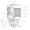
- nachspannender drill chuck which comprise a chuck body 2 having a chuck body 1, which has a coaxial with the chuck body 1 rotatable clamping cone 3.
- the clamping cone 3 is axially supported on a bearing on the chuck body 1 jaw holder 4, in which 5 guide jaws 6 are guided in guide slots, which further guided radially adjustable on a driver 7 and for clamping and releasing by a relative rotation between the chuck body 1 and the clamping cone. 3 can be adjusted with the jaw holder 4.
- the driver 7 engages with a driver thread 8 in a coaxial with the chuck axis 9 formed spindle thread 10 a cam receiver 11 of the chuck body 1 a.
- a sealing disc 12 is arranged, which engages in the embodiment shown in FIG. 1 with a sealing lip 13 in the driver thread 8.
- the sealing disk 12 consists of an elastic, preferably rubber-like material and thus also exerts a damping function when the driver 7 strikes the lining body 1 during the adjustment of the clamping jaws 6 in the axially rearward extreme position.
- a damping disk 14 is arranged on the side facing the chuck body 1 of the driver 7.
- Fig. 1 but in particular Figs. 5 and 6 show that in the jaw holder 4 and the clamping cone 3 mutually aligned dedusting openings 15 are formed, which allow a simpler removal of penetrated into the chuck Bohrstaub.
- the dedusting openings 15 also effect a saving of material from the jaw holder 4 and the clamping cone 3, so that their weight and thus the weight of the chuck are reduced overall.
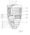
- the sealing disk 12 extends radially as far as the clamping cone 3 and has on the side facing the clamping jaws 6 at least one guide web 16 which is illustrated in the drawing (FIG. 2) on, leading to the dedusting 15.
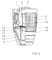
- Figs. 3 and 4 show a further improved in terms of their protective effect against Bohrdaub embodiment in which the sealing disc 12 a Baling tube 17 is assigned, which is fixed with its axially front, the clamping jaws 6 end facing the driver 7 and thus causes a complete encapsulation of the driver 7 and the cam receiver 11.
- the bellows tube 17 has at its end assigned to the driver 7 an annular bead 18 which engages in an annular groove 19 formed on the driver 7 axially in front of the driver thread 8.
Landscapes
- Engineering & Computer Science (AREA)
- Mechanical Engineering (AREA)
- Gripping On Spindles (AREA)
- Processing Of Stones Or Stones Resemblance Materials (AREA)
- Steroid Compounds (AREA)
- Surgical Instruments (AREA)
- Saccharide Compounds (AREA)
- Earth Drilling (AREA)
- Drilling And Boring (AREA)
Abstract
Description
- Die Erfindung betrifft ein Bohrfutter mit einem an eine Bohrspindel koppelbaren Futterkörper, der einen koaxial zum Futterkörper verdrehbaren Spannkonus aufweist, der axial auf einem am Futterkörper gelagerten Backenhalter abgestützt ist, in dem in Führungsschlitzen Spannbacken geführt sind, die radial verstellbar an einem Mitnehmer geführt und zum Spannen und Lösen durch eine Relativdrehung zwischen dem Futterkörper und dem Spannkonus mit dem Backenhalter verstellbar sind, wozu der Mitnehmer mit einem Mitnehmergewinde in ein koaxial zur Futterachse ausgebildetes Spindelgewinde einer Mitnehmeraufnahme des Futterkörpers eingreift.
- Derartige als nachspannend bezeichnete Bohrfutter sind beispielsweise aus der
DE 37 39 165 A1 bekannt. Diese Bohrfutter haben sich in der Praxis gut bewährt, insbesondere da mit diesen eine hohe Spannkraft erreicht werden kann. Als problematisch hat sich allerdings erwiesen, dass während des Bohrbetriebes in das Bohrfutter eindringender Bohrstaub sich dort ansammelt und insbesondere die Gängigkeit des Mitnehmergewindes in dem Spindelgewinde beeinträchtigen kann. - Der Erfindung liegt daher die Aufgabe zugrunde, ein Bohrfutter der eingangs genannten Art so auszubilden, dass eine einfache Verstellbarkeit des Mitnehmergewindes in dem Spindelgewinde über die gesamte Lebensdauer des Bohrfutters gewährleistet ist.
- Diese Aufgabe wird nach der Erfindung bei einem Bohrfutter der eingangs genannten Art dadurch gelöst, dass am Futterkörper dem Mitnehmer zugewandt eine Dichtungsscheibe angeordnet ist.
- Diese Dichtungsscheibe übt im wesentlichen zwei Funktionen aus, nämlich zum einen wird durch die Dichtungsscheibe das Eindringen von Bohrstaub in die des Spindelgewinde bereitstellende Mitnehmeraufnahme verhindert, zum anderen erfolgt eine permanente Reinigung des Mitnehmergewindes, die besonders effektiv ist, wenn die Dichtungsscheibe am axial vorderen Ende des Futterkörpers angeordnet ist und mit einer Dichtungslippe in das Mitnehmergewinde eingreift.
- Ein weiterer Vorteil lässt sich erzielen, wenn die Dichtungsscheibe aus einem elastischen, vorzugsweise gummiartigen Material besteht, da so beim Öffnen des Bohrfutters, insbesondere wenn dies motorisch mit dem Bohrspindelantrieb der Bohrmaschine erfolgt, die Spannbacken zusammen mit dem Mitnehmer axial nach hinten verstellt werden und einer Verklemmung des Mitnehmergewindes in dem Spindelgewinde infolge der von der Dichtungsscheibe ausgeübten Dämpfung entgegen gewirkt wird.
- Diese Wirkung lässt sich verstärken, wenn auf der dem Futterkörper zugewandten Seite des Mitnehmers eine Dämpfungsscheibe angeordnet ist, die der Dichtungsscheibe anliegt in der maximal geöffneten Stellung der Spannbacken, so dass diese maximal geöffnete Stellung der Spannbacken sich auch anbietet, um beispielsweise durch Erschütterungen des Bohrfutters in dieses eingedrungenen Bohrstaub wieder zu entfernen.
- Ein Entfernen des in das Bohrfutter eingedrungenen Bohrstaubes wird dadurch erleichtert, dass in dem Backenhalter und dem Spannkonus miteinander fluchtenden Entstaubungsöffnungen ausgebildet sind. Dabei bietet sich dann gemäß einer bevorzugten Ausführungsform an, dass die Dichtungsscheibe sich radial bis zum Spannkonus erstreckt, wobei zweckmäßigerweise auf der den Spannbacken zugewandten Seite der Dichtungsscheibe ein zu den Entstaubungsöffnungen weisender Leitsteg ausgebildet ist, der die Entstaubung des Bohrfutter unterstützten und insbesondere im Bohrbetrieb unter Ausnutzung der Wirkung der Fliehkraft den gezielten Transport des Bohrstaubes zu den Entstaubungsöffnungen ermöglicht.
- Eine weitere bevorzugte Ausführungsform der Erfindung ist dadurch gekennzeichnet, dass der Dichtungsscheibe ein Balgentubus zugeordnet ist, der mit seinem axial vorderen, den Spannbacken zugewandten Ende am Mitnehmer fixiert ist. Dieser Balgentubus stellt eine vollständige Kapselung des Mitnehmers mit der Mitnehmeraufnahme dar, durch die das Eindringen von Bohrstaub in diesen Bereich vermieden wird. Auf dem Balgentubus abgelagerter Bohrstaub wird dabei durch die bei der Verstellung der Spannbacken erfolgende ziehharmonikaartige Bewegung von der Oberfläche des Balgentubus gelöst, wodurch ein einfacherer Transport nach aussen, insbesodere durch die Entstaubungsöffnungen möglich ist.
- Für eine dauerhafte, der Lebensdauer des Bohrfutters angepasste Fixierung des Balgentubus am Mitnehmer ist vorgesehen, dass der Balgentubus an seinem dem Mitnehmer zugeordneten Ende einen Ringwulst aufweist, der in eine am Mitnehmer axial vor dem Mitnehmergewinde ausgebildete Ringnut eingreift.
- Im folgenden wird die Erfindung an in der Zeichnung dargestellten Ausführungsbeispielen näher erläutert; es zeigen:
- Fig. 1
- ein Bohrfutter nach der Erfindung, links in einem Axialschnitt, rechts in einer Seitenansicht dargestellt,
- Fig. 2
- eine der Fig. 1 entsprechende Darstellung einer alternativen Ausführungsform,
- Fig. 3
- eine der Fig. 1 entsprechende Darstellung einer weiteren alternativen Ausführungsform mit einem Balgentubus, gezeigt in der gestreckten Konfiguration in der zu einem kleinen Spanndurchmesser gehörenden Spannstellung der Spannbacken,
- Fig. 4
- eine Darstellung des Bohrfutters aus Fig. 3 in der komprimierten Konfiguration des Balgentubus, gehörend zu der zu einem großen Spanndurchmesser entsprechenden Stellung der Spannbacken,
- Fig. 5
- eine weitere Ausführungsform mit den in dem Backenhalter und dem Spannkonus ausgebildeten Entstaubungsöffnungen, und
- Fig. 6
- eine der Fig. 5 entsprechende Darstellung mit der einem großen Spanndurchmesser entsprechenden Stellung der Spannbacken.
- In der Zeichnung sind Ausführungsformen sogenannter nachspannender Bohrfutter gezeigt, die einen eine Spindelaufnahme 2 aufweisenden Futterkörper 1 umfassen, der einen koaxial zum Futterkörper 1 verdrehbaren Spannkonus 3 aufweist. Der Spannkonus 3 ist axial auf einem am Futterkörper 1 gelagerten Backenhalter 4 abgestützt, in dem in Führungsschlitzen 5 Spannbacken 6 geführt sind, die weiterhin radial verstellbar an einem Mitnehmer 7 geführt und zum Spannen und Lösen durch eine Relativdrehung zwischen dem Futterkörper 1 und dem Spannkonus 3 mit dem Backenhalter 4 verstellbar sind. Dazu greift der Mitnehmer 7 mit einem Mitnehmergewinde 8 in ein koaxial zur Futterachse 9 ausgebildetes Spindelgewinde 10 einer Mitnehmeraufnahme 11 des Futterkörpers 1 ein. Am axial vorderen Ende des Futterkörpers 1, also dem Mitnehmer 7 zugewandt, ist eine Dichtungsscheibe 12 angeordnet, die bei dem in der Fig. 1 gezeigten Ausführungsbeispiel mit einer Dichtungslippe 13 in das Mitnehmergewinde 8 eingreift. Die Dichtungsscheibe 12 besteht aus einem elastischen, vorzugsweise gummiartigen Material und übt somit auch eine Dämpfungsfunktion aus, wenn der Mitnehmer 7 bei der Verstellung der Spannbacken 6 in die axial rückwärtige Extremposition auf den Futterköper 1 trifft. Zur Verstärkung der Dämpfungswirkung ist auf der dem Futterkörper 1 zugewandten Seite des Mitnehmers 7 eine Dämpfungsscheibe 14 angeordnet.
- Fig. 1, insbesondere aber die Fig. 5 und 6 lassen erkennen, dass in dem Backenhalter 4 und dem Spannkonus 3 miteinander fluchtende Entstaubungsöffnungen 15 aufgebildet sind, die ein einfacheres Entfernen von in das Bohrfutter eingedrungenen Bohrstaub ermöglichen. Zugleich bewirken die Entstaubungsöffnungen 15 auch eine Materialeinsparung von dem Backenhalter 4 und dem Spannkonus 3, so dass deren Gewicht und damit das Gewicht des Bohrfutters insgesamt reduziert ist. Um eine gezielte Ableitung von in das Bohrfutter eingedrungenen Bohrstaub zu ermöglichen, erstreckt die Dichtungsscheibe 12 sich radial bis zum Spannkonus 3 und weist auf der den Spannbacken 6 zugewandten Seite mindestens einen, bei dem in der Zeichnung (Fig. 2) dargestellten Ausführungsbeispiel mehrere Leitstege 16 auf, die zu den Entstaubungsöffnungen 15 führen.
- Die Fig. 3 und 4 zeigen eine hinsichtlich ihrer Schutzwirkung gegen Bohrstaub weiter verbesserte Ausführungsform, bei der der Dichtungsscheibe 12 ein Balgentubus 17 zugeordnet ist, der mit seinem axial vorderen, den Spannbacken 6 zugewandten Ende am Mitnehmer 7 fixiert ist und so eine vollständige Kapselung des Mitnehmers 7 und der Mitnehmeraufnahme 11 bewirkt. Fig. 3 lässt dabei erkennen, dass der Balgentubus 17 an seinem dem Mitnehmer 7 zugeordneten Ende einen Ringwulst 18 aufweist, der in eine am Mitnehmer 7 axial vor dem Mitnehmergewinde 8 ausgebildete Ringnut 19 eingreift.
Claims (9)
- Bohrfutter mit einem an eine Bohrspindel koppelbaren Futterkörper (1), der einen koaxial zum Futterkörper (1) verdrehbaren Spannkonus (3) aufweist, der axial auf einem am Futterkörper (1) gelagerten Backenhalter (4) abgestützt ist, in dem in Führungsschlitzen (5) Spannbacken (6) geführt sind, die radial verstellbar an einem Mitnehmer (7) geführt und zum Spannen und Lösen durch eine Relativdrehung zwischen dem Futterkörper (1) und dem Spannkonus (3) mit dem Backenhalter (4) verstellbar sind, wozu der Mitnehmer (7) mit einem Mitnehmergewinde (8) in ein koaxial zur Futterachse (9) ausgebildetes Spindelgewinde (10) einer Mitnehmeraufnahme (11) des Futterkörpers (1) eingreift, dadurch gekennzeichnet, dass am Futterkörper (1) dem Mitnehmer (7) zugewandt eine Dichtungsscheibe (12) angeordnet ist.
- Bohrfutter nach Anspruch 1, dadurch gekennzeichnet, dass die Dichtungsscheibe (12) am axial vorderen Ende des Futterkörpers (1) angeordnet ist und mit einer Dichtungslippe (13) in das Mitnehmergewinde (8) eingreift.
- Bohrfutter nach Anspruch 1 oder 2, dadurch gekennzeichnet, dass die Dichtungsscheibe (12) aus einem elastischen, vorzugsweise gummiartigen Material besteht.
- Bohrfutter nach einem der Ansprüche 1 bis 3, dadurch gekennzeichnet, dass auf der dem Futterkörper (1) zugewandten Seite des Mitnehmers (7) eine Dämpfungsscheibe (14) angeordnet ist.
- Bohrfutter nach einem der Ansprüche 1 bis 4, dadurch gekennzeichnet, dass in dem Backenhalter (4) und dem Spannkonus (3) miteinander fluchtende Entstaubungsöffnungen (15) ausgebildet sind.
- Bohrfutter nach einem der Ansprüche 1 bis 5, dadurch gekennzeichnet, dass die Dichtungsscheibe (12) sich radial bis zum Spannkonus (3) erstreckt.
- Bohrfutter nach Anspruch 5 oder 6, dadurch gekennzeichnet, dass auf der den Spannbacken (6) zugewandten Seite der Dichtungsscheibe (12) ein zu den Entstaubungsöffnungen (15) weisender Leitsteg (16) zugeordnet ist.
- Bohrfutter nach einem der Ansprüche 1 bis 7, dadurch gekennzeichnet, dass der Dichtungsscheibe (12) ein Balgentubus (17) zugeordnet ist, der mit seinem axial vorderen, den Spannbacken (6) zugewandten Seite am Mitnehmer (7) fixiert ist.
- Bohrfutter nach Anspruch 8, dadurch gekennzeichnet, dass der Balgentubus (17) an seinem dem Mitnehmer (7) zugeordneten Ende einen Ringwulst (18) aufweist, der in eine am Mitnehmer (7) axial vor dem Mitnehmergewinde (8) ausgebildete Ringnut (19) eingreift.
Applications Claiming Priority (1)
| Application Number | Priority Date | Filing Date | Title |
|---|---|---|---|
| DE102005027523A DE102005027523A1 (de) | 2005-06-15 | 2005-06-15 | Bohrvorrichtung |
Publications (2)
| Publication Number | Publication Date |
|---|---|
| EP1733830A1 true EP1733830A1 (de) | 2006-12-20 |
| EP1733830B1 EP1733830B1 (de) | 2009-10-21 |
Family
ID=36954509
Family Applications (2)
| Application Number | Title | Priority Date | Filing Date |
|---|---|---|---|
| EP05021862A Expired - Lifetime EP1733829B1 (de) | 2005-06-15 | 2005-10-07 | Bohrvorrichtung |
| EP06001776A Expired - Lifetime EP1733830B1 (de) | 2005-06-15 | 2006-01-28 | Bohrfutter |
Family Applications Before (1)
| Application Number | Title | Priority Date | Filing Date |
|---|---|---|---|
| EP05021862A Expired - Lifetime EP1733829B1 (de) | 2005-06-15 | 2005-10-07 | Bohrvorrichtung |
Country Status (4)
| Country | Link |
|---|---|
| EP (2) | EP1733829B1 (de) |
| CN (1) | CN1879992B (de) |
| AT (2) | ATE446817T1 (de) |
| DE (3) | DE102005027523A1 (de) |
Families Citing this family (3)
| Publication number | Priority date | Publication date | Assignee | Title |
|---|---|---|---|---|
| DE102013106523B4 (de) * | 2013-06-21 | 2024-02-08 | Röhm Gmbh | Bohrvorrichtung |
| CN104511618B (zh) * | 2013-09-30 | 2018-10-02 | 南京德朔实业有限公司 | 电钻 |
| CN104874825A (zh) * | 2015-06-15 | 2015-09-02 | 楼国华 | 一种钻孔装置 |
Citations (5)
| Publication number | Priority date | Publication date | Assignee | Title |
|---|---|---|---|---|
| DE1810614A1 (de) * | 1968-11-23 | 1970-06-04 | Metabowerke Kg | Bohrfutter |
| CH567897A5 (de) * | 1973-03-15 | 1975-10-15 | Roehm Guenter H | |
| GB2090776A (en) * | 1981-01-10 | 1982-07-21 | Metabowerke Kg | A drill chuck |
| DE3305733A1 (de) | 1982-02-22 | 1983-09-01 | Micron, S.A., Montgat, Barcelona | Spannbohrfuttermechanismus fuer schluessellose schnellbefestigung |
| DE3739165A1 (de) | 1987-11-19 | 1989-06-01 | Roehm Guenter H | Selbstspannendes bohrfutter |
Family Cites Families (4)
| Publication number | Priority date | Publication date | Assignee | Title |
|---|---|---|---|---|
| DE7910976U1 (de) | 1979-04-14 | 1979-07-19 | Roehm, Guenter Horst, 7927 Sontheim | Nachspannendes bohrfutter |
| JPS62166906A (ja) * | 1986-01-21 | 1987-07-23 | Matsushita Electric Works Ltd | 締め付け具 |
| JPH0283105A (ja) | 1988-03-28 | 1990-03-23 | Matsushita Electric Works Ltd | 締め付け具 |
| JP3108654B2 (ja) * | 1996-08-27 | 2000-11-13 | 健吾 堀内 | キーレスドリルチャック |
-
2005
- 2005-06-15 DE DE102005027523A patent/DE102005027523A1/de not_active Withdrawn
- 2005-10-07 DE DE502005008407T patent/DE502005008407D1/de not_active Expired - Lifetime
- 2005-10-07 AT AT05021862T patent/ATE446817T1/de not_active IP Right Cessation
- 2005-10-07 EP EP05021862A patent/EP1733829B1/de not_active Expired - Lifetime
-
2006
- 2006-01-28 EP EP06001776A patent/EP1733830B1/de not_active Expired - Lifetime
- 2006-01-28 DE DE502006005151T patent/DE502006005151D1/de not_active Expired - Lifetime
- 2006-01-28 AT AT06001776T patent/ATE446153T1/de not_active IP Right Cessation
- 2006-06-15 CN CN2006100936820A patent/CN1879992B/zh not_active Expired - Fee Related
Patent Citations (5)
| Publication number | Priority date | Publication date | Assignee | Title |
|---|---|---|---|---|
| DE1810614A1 (de) * | 1968-11-23 | 1970-06-04 | Metabowerke Kg | Bohrfutter |
| CH567897A5 (de) * | 1973-03-15 | 1975-10-15 | Roehm Guenter H | |
| GB2090776A (en) * | 1981-01-10 | 1982-07-21 | Metabowerke Kg | A drill chuck |
| DE3305733A1 (de) | 1982-02-22 | 1983-09-01 | Micron, S.A., Montgat, Barcelona | Spannbohrfuttermechanismus fuer schluessellose schnellbefestigung |
| DE3739165A1 (de) | 1987-11-19 | 1989-06-01 | Roehm Guenter H | Selbstspannendes bohrfutter |
Also Published As
| Publication number | Publication date |
|---|---|
| EP1733829A1 (de) | 2006-12-20 |
| ATE446817T1 (de) | 2009-11-15 |
| CN1879992A (zh) | 2006-12-20 |
| DE102005027523A1 (de) | 2006-12-21 |
| DE502006005151D1 (de) | 2009-12-03 |
| DE502005008407D1 (de) | 2009-12-10 |
| CN1879992B (zh) | 2010-06-16 |
| EP1733829B1 (de) | 2009-10-28 |
| EP1733830B1 (de) | 2009-10-21 |
| ATE446153T1 (de) | 2009-11-15 |
Similar Documents
| Publication | Publication Date | Title |
|---|---|---|
| DE4416224C1 (de) | Schlüsselloses Spannfutter | |
| EP1224993B1 (de) | Bohrfutter | |
| EP0900613B1 (de) | Bohrfutter | |
| DE19729249C2 (de) | Spannfutter | |
| DE10106251B4 (de) | Bohrfutter | |
| DE3132450C2 (de) | ||
| DE102009044049A1 (de) | Spannzangenfutter | |
| EP0331867A2 (de) | Zum Anschluss an eine Bohrspindel eingerichtetes Bohrfutter | |
| DE2853045C2 (de) | Bohrfutter | |
| EP1855829B1 (de) | Spannsystem | |
| EP0245629A2 (de) | Spanneinrichtung an Drehspindeln von Drehmaschinen für kraftbetätigte Werkstückhalter, insbesondere Spannfutter | |
| DE102009003802A1 (de) | Spannfutter | |
| EP1733830B1 (de) | Bohrfutter | |
| DE10137281A1 (de) | Bohrfutter | |
| DE69725185T2 (de) | Handbetätigtes futter | |
| DE102017116617A1 (de) | Spannzangenfutter | |
| DE1491029A1 (de) | Zahnaertzliches Handstueck | |
| DE19918638C2 (de) | Anschlußstück für einen Bohrer zum Erzeugen von Bohrungen in Knochengewebe, Bohrer und Bohrgerät | |
| DE10149959A1 (de) | Bohrvorrichtung | |
| DE102016110111A1 (de) | Bohrfutter | |
| DE19513748A1 (de) | Vorrichtung zur Aufnahme von Bohrrückständen für Bohrmaschinen | |
| DE3024996C2 (de) | ||
| DE3346440C2 (de) | Bohrfutter, insbesondere Hammerbohrfutter | |
| DE202013101255U1 (de) | Bohrfutter | |
| DE717362C (de) | Mitnehmereinrichtung fuer umlaufende Zufuehrungsrohre fuer stangenfoermigen Werkstoff bei stangenverarbeitenden Drehbaenken u. dgl. |
Legal Events
| Date | Code | Title | Description |
|---|---|---|---|
| PUAI | Public reference made under article 153(3) epc to a published international application that has entered the european phase |
Free format text: ORIGINAL CODE: 0009012 |
|
| 17P | Request for examination filed |
Effective date: 20061018 |
|
| AK | Designated contracting states |
Kind code of ref document: A1 Designated state(s): AT BE BG CH CY CZ DE DK EE ES FI FR GB GR HU IE IS IT LI LT LU LV MC NL PL PT RO SE SI SK TR |
|
| AX | Request for extension of the european patent |
Extension state: AL BA HR MK YU |
|
| 17Q | First examination report despatched |
Effective date: 20070427 |
|
| AKX | Designation fees paid |
Designated state(s): AT BE BG CH CY CZ DE DK EE ES FI FR GB GR HU IE IS IT LI LT LU LV MC NL PL PT RO SE SI SK TR |
|
| RAP1 | Party data changed (applicant data changed or rights of an application transferred) |
Owner name: EVONIK ROEHM GMBH |
|
| RAP1 | Party data changed (applicant data changed or rights of an application transferred) |
Owner name: ROEHM GMBH |
|
| GRAP | Despatch of communication of intention to grant a patent |
Free format text: ORIGINAL CODE: EPIDOSNIGR1 |
|
| GRAS | Grant fee paid |
Free format text: ORIGINAL CODE: EPIDOSNIGR3 |
|
| GRAA | (expected) grant |
Free format text: ORIGINAL CODE: 0009210 |
|
| AK | Designated contracting states |
Kind code of ref document: B1 Designated state(s): AT BE BG CH CY CZ DE DK EE ES FI FR GB GR HU IE IS IT LI LT LU LV MC NL PL PT RO SE SI SK TR |
|
| REG | Reference to a national code |
Ref country code: GB Ref legal event code: FG4D Free format text: NOT ENGLISH |
|
| REG | Reference to a national code |
Ref country code: CH Ref legal event code: EP |
|
| REG | Reference to a national code |
Ref country code: IE Ref legal event code: FG4D |
|
| REF | Corresponds to: |
Ref document number: 502006005151 Country of ref document: DE Date of ref document: 20091203 Kind code of ref document: P |
|
| LTIE | Lt: invalidation of european patent or patent extension |
Effective date: 20091021 |
|
| NLV1 | Nl: lapsed or annulled due to failure to fulfill the requirements of art. 29p and 29m of the patents act | ||
| PG25 | Lapsed in a contracting state [announced via postgrant information from national office to epo] |
Ref country code: PT Free format text: LAPSE BECAUSE OF FAILURE TO SUBMIT A TRANSLATION OF THE DESCRIPTION OR TO PAY THE FEE WITHIN THE PRESCRIBED TIME-LIMIT Effective date: 20100222 Ref country code: LT Free format text: LAPSE BECAUSE OF FAILURE TO SUBMIT A TRANSLATION OF THE DESCRIPTION OR TO PAY THE FEE WITHIN THE PRESCRIBED TIME-LIMIT Effective date: 20091021 Ref country code: ES Free format text: LAPSE BECAUSE OF FAILURE TO SUBMIT A TRANSLATION OF THE DESCRIPTION OR TO PAY THE FEE WITHIN THE PRESCRIBED TIME-LIMIT Effective date: 20100201 Ref country code: IS Free format text: LAPSE BECAUSE OF FAILURE TO SUBMIT A TRANSLATION OF THE DESCRIPTION OR TO PAY THE FEE WITHIN THE PRESCRIBED TIME-LIMIT Effective date: 20100221 Ref country code: FI Free format text: LAPSE BECAUSE OF FAILURE TO SUBMIT A TRANSLATION OF THE DESCRIPTION OR TO PAY THE FEE WITHIN THE PRESCRIBED TIME-LIMIT Effective date: 20091021 Ref country code: SE Free format text: LAPSE BECAUSE OF FAILURE TO SUBMIT A TRANSLATION OF THE DESCRIPTION OR TO PAY THE FEE WITHIN THE PRESCRIBED TIME-LIMIT Effective date: 20091021 |
|
| REG | Reference to a national code |
Ref country code: IE Ref legal event code: FD4D |
|
| PG25 | Lapsed in a contracting state [announced via postgrant information from national office to epo] |
Ref country code: SI Free format text: LAPSE BECAUSE OF FAILURE TO SUBMIT A TRANSLATION OF THE DESCRIPTION OR TO PAY THE FEE WITHIN THE PRESCRIBED TIME-LIMIT Effective date: 20091021 Ref country code: PL Free format text: LAPSE BECAUSE OF FAILURE TO SUBMIT A TRANSLATION OF THE DESCRIPTION OR TO PAY THE FEE WITHIN THE PRESCRIBED TIME-LIMIT Effective date: 20091021 Ref country code: LV Free format text: LAPSE BECAUSE OF FAILURE TO SUBMIT A TRANSLATION OF THE DESCRIPTION OR TO PAY THE FEE WITHIN THE PRESCRIBED TIME-LIMIT Effective date: 20091021 |
|
| PG25 | Lapsed in a contracting state [announced via postgrant information from national office to epo] |
Ref country code: RO Free format text: LAPSE BECAUSE OF FAILURE TO SUBMIT A TRANSLATION OF THE DESCRIPTION OR TO PAY THE FEE WITHIN THE PRESCRIBED TIME-LIMIT Effective date: 20091021 Ref country code: IE Free format text: LAPSE BECAUSE OF FAILURE TO SUBMIT A TRANSLATION OF THE DESCRIPTION OR TO PAY THE FEE WITHIN THE PRESCRIBED TIME-LIMIT Effective date: 20091021 Ref country code: BG Free format text: LAPSE BECAUSE OF FAILURE TO SUBMIT A TRANSLATION OF THE DESCRIPTION OR TO PAY THE FEE WITHIN THE PRESCRIBED TIME-LIMIT Effective date: 20100121 Ref country code: DK Free format text: LAPSE BECAUSE OF FAILURE TO SUBMIT A TRANSLATION OF THE DESCRIPTION OR TO PAY THE FEE WITHIN THE PRESCRIBED TIME-LIMIT Effective date: 20091021 Ref country code: EE Free format text: LAPSE BECAUSE OF FAILURE TO SUBMIT A TRANSLATION OF THE DESCRIPTION OR TO PAY THE FEE WITHIN THE PRESCRIBED TIME-LIMIT Effective date: 20091021 |
|
| BERE | Be: lapsed |
Owner name: ROHM G.M.B.H. Effective date: 20100131 |
|
| PLBE | No opposition filed within time limit |
Free format text: ORIGINAL CODE: 0009261 |
|
| STAA | Information on the status of an ep patent application or granted ep patent |
Free format text: STATUS: NO OPPOSITION FILED WITHIN TIME LIMIT |
|
| PG25 | Lapsed in a contracting state [announced via postgrant information from national office to epo] |
Ref country code: CZ Free format text: LAPSE BECAUSE OF FAILURE TO SUBMIT A TRANSLATION OF THE DESCRIPTION OR TO PAY THE FEE WITHIN THE PRESCRIBED TIME-LIMIT Effective date: 20091021 Ref country code: MC Free format text: LAPSE BECAUSE OF NON-PAYMENT OF DUE FEES Effective date: 20100131 Ref country code: SK Free format text: LAPSE BECAUSE OF FAILURE TO SUBMIT A TRANSLATION OF THE DESCRIPTION OR TO PAY THE FEE WITHIN THE PRESCRIBED TIME-LIMIT Effective date: 20091021 |
|
| REG | Reference to a national code |
Ref country code: CH Ref legal event code: PL |
|
| 26N | No opposition filed |
Effective date: 20100722 |
|
| PG25 | Lapsed in a contracting state [announced via postgrant information from national office to epo] |
Ref country code: CH Free format text: LAPSE BECAUSE OF NON-PAYMENT OF DUE FEES Effective date: 20100131 Ref country code: LI Free format text: LAPSE BECAUSE OF NON-PAYMENT OF DUE FEES Effective date: 20100131 Ref country code: GR Free format text: LAPSE BECAUSE OF FAILURE TO SUBMIT A TRANSLATION OF THE DESCRIPTION OR TO PAY THE FEE WITHIN THE PRESCRIBED TIME-LIMIT Effective date: 20100122 |
|
| PG25 | Lapsed in a contracting state [announced via postgrant information from national office to epo] |
Ref country code: BE Free format text: LAPSE BECAUSE OF NON-PAYMENT OF DUE FEES Effective date: 20100131 |
|
| PG25 | Lapsed in a contracting state [announced via postgrant information from national office to epo] |
Ref country code: IT Free format text: LAPSE BECAUSE OF FAILURE TO SUBMIT A TRANSLATION OF THE DESCRIPTION OR TO PAY THE FEE WITHIN THE PRESCRIBED TIME-LIMIT Effective date: 20091021 |
|
| REG | Reference to a national code |
Ref country code: AT Ref legal event code: MM01 Ref document number: 446153 Country of ref document: AT Kind code of ref document: T Effective date: 20110128 |
|
| PG25 | Lapsed in a contracting state [announced via postgrant information from national office to epo] |
Ref country code: CY Free format text: LAPSE BECAUSE OF FAILURE TO SUBMIT A TRANSLATION OF THE DESCRIPTION OR TO PAY THE FEE WITHIN THE PRESCRIBED TIME-LIMIT Effective date: 20091021 |
|
| PG25 | Lapsed in a contracting state [announced via postgrant information from national office to epo] |
Ref country code: NL Free format text: LAPSE BECAUSE OF FAILURE TO SUBMIT A TRANSLATION OF THE DESCRIPTION OR TO PAY THE FEE WITHIN THE PRESCRIBED TIME-LIMIT Effective date: 20091021 Ref country code: LU Free format text: LAPSE BECAUSE OF NON-PAYMENT OF DUE FEES Effective date: 20100128 Ref country code: HU Free format text: LAPSE BECAUSE OF FAILURE TO SUBMIT A TRANSLATION OF THE DESCRIPTION OR TO PAY THE FEE WITHIN THE PRESCRIBED TIME-LIMIT Effective date: 20100422 |
|
| PG25 | Lapsed in a contracting state [announced via postgrant information from national office to epo] |
Ref country code: TR Free format text: LAPSE BECAUSE OF FAILURE TO SUBMIT A TRANSLATION OF THE DESCRIPTION OR TO PAY THE FEE WITHIN THE PRESCRIBED TIME-LIMIT Effective date: 20091021 |
|
| PG25 | Lapsed in a contracting state [announced via postgrant information from national office to epo] |
Ref country code: AT Free format text: LAPSE BECAUSE OF NON-PAYMENT OF DUE FEES Effective date: 20110128 |
|
| PGFP | Annual fee paid to national office [announced via postgrant information from national office to epo] |
Ref country code: DE Payment date: 20130211 Year of fee payment: 8 Ref country code: GB Payment date: 20130128 Year of fee payment: 8 Ref country code: FR Payment date: 20130219 Year of fee payment: 8 |
|
| REG | Reference to a national code |
Ref country code: DE Ref legal event code: R119 Ref document number: 502006005151 Country of ref document: DE |
|
| GBPC | Gb: european patent ceased through non-payment of renewal fee |
Effective date: 20140128 |
|
| REG | Reference to a national code |
Ref country code: DE Ref legal event code: R119 Ref document number: 502006005151 Country of ref document: DE Effective date: 20140801 |
|
| PG25 | Lapsed in a contracting state [announced via postgrant information from national office to epo] |
Ref country code: DE Free format text: LAPSE BECAUSE OF NON-PAYMENT OF DUE FEES Effective date: 20140801 |
|
| REG | Reference to a national code |
Ref country code: FR Ref legal event code: ST Effective date: 20140930 |
|
| PG25 | Lapsed in a contracting state [announced via postgrant information from national office to epo] |
Ref country code: GB Free format text: LAPSE BECAUSE OF NON-PAYMENT OF DUE FEES Effective date: 20140128 Ref country code: FR Free format text: LAPSE BECAUSE OF NON-PAYMENT OF DUE FEES Effective date: 20140131 |