EP1731748A1 - Vorrichtung zur gekühlten Rückführung von Abgas einer Brennkraftmaschine eines Kraftfahrzeuges - Google Patents
Vorrichtung zur gekühlten Rückführung von Abgas einer Brennkraftmaschine eines Kraftfahrzeuges Download PDFInfo
- Publication number
- EP1731748A1 EP1731748A1 EP06005344A EP06005344A EP1731748A1 EP 1731748 A1 EP1731748 A1 EP 1731748A1 EP 06005344 A EP06005344 A EP 06005344A EP 06005344 A EP06005344 A EP 06005344A EP 1731748 A1 EP1731748 A1 EP 1731748A1
- Authority
- EP
- European Patent Office
- Prior art keywords
- exhaust gas
- compressor
- charge air
- cooler
- egr
- Prior art date
- Legal status (The legal status is an assumption and is not a legal conclusion. Google has not performed a legal analysis and makes no representation as to the accuracy of the status listed.)
- Withdrawn
Links
- 238000002485 combustion reaction Methods 0.000 title claims description 11
- 238000001816 cooling Methods 0.000 title claims description 9
- 239000002826 coolant Substances 0.000 claims description 7
- 239000007788 liquid Substances 0.000 claims description 2
- 238000007789 sealing Methods 0.000 claims description 2
- 230000006698 induction Effects 0.000 abstract 2
- 239000007789 gas Substances 0.000 description 63
- 239000003570 air Substances 0.000 description 26
- 230000007797 corrosion Effects 0.000 description 6
- 238000005260 corrosion Methods 0.000 description 6
- XAGFODPZIPBFFR-UHFFFAOYSA-N aluminium Chemical compound [Al] XAGFODPZIPBFFR-UHFFFAOYSA-N 0.000 description 5
- 229910052782 aluminium Inorganic materials 0.000 description 5
- 230000002378 acidificating effect Effects 0.000 description 4
- MWUXSHHQAYIFBG-UHFFFAOYSA-N Nitric oxide Chemical compound O=[N] MWUXSHHQAYIFBG-UHFFFAOYSA-N 0.000 description 3
- 239000000203 mixture Substances 0.000 description 3
- 239000012080 ambient air Substances 0.000 description 2
- 238000000746 purification Methods 0.000 description 2
- 239000010935 stainless steel Substances 0.000 description 2
- 229910001220 stainless steel Inorganic materials 0.000 description 2
- 229910000838 Al alloy Inorganic materials 0.000 description 1
- 239000002253 acid Substances 0.000 description 1
- 239000003054 catalyst Substances 0.000 description 1
- 230000006835 compression Effects 0.000 description 1
- 238000007906 compression Methods 0.000 description 1
- 238000010276 construction Methods 0.000 description 1
- 238000010586 diagram Methods 0.000 description 1
- 239000003344 environmental pollutant Substances 0.000 description 1
- 239000000463 material Substances 0.000 description 1
- 230000003647 oxidation Effects 0.000 description 1
- 238000007254 oxidation reaction Methods 0.000 description 1
- 239000002245 particle Substances 0.000 description 1
- 231100000719 pollutant Toxicity 0.000 description 1
- 239000002244 precipitate Substances 0.000 description 1
- 238000005070 sampling Methods 0.000 description 1
- 238000000926 separation method Methods 0.000 description 1
Images

Classifications
-
- F—MECHANICAL ENGINEERING; LIGHTING; HEATING; WEAPONS; BLASTING
- F02—COMBUSTION ENGINES; HOT-GAS OR COMBUSTION-PRODUCT ENGINE PLANTS
- F02M—SUPPLYING COMBUSTION ENGINES IN GENERAL WITH COMBUSTIBLE MIXTURES OR CONSTITUENTS THEREOF
- F02M26/00—Engine-pertinent apparatus for adding exhaust gases to combustion-air, main fuel or fuel-air mixture, e.g. by exhaust gas recirculation [EGR] systems
- F02M26/13—Arrangement or layout of EGR passages, e.g. in relation to specific engine parts or for incorporation of accessories
- F02M26/34—Arrangement or layout of EGR passages, e.g. in relation to specific engine parts or for incorporation of accessories with compressors, turbines or the like in the recirculation passage
-
- F—MECHANICAL ENGINEERING; LIGHTING; HEATING; WEAPONS; BLASTING
- F02—COMBUSTION ENGINES; HOT-GAS OR COMBUSTION-PRODUCT ENGINE PLANTS
- F02M—SUPPLYING COMBUSTION ENGINES IN GENERAL WITH COMBUSTIBLE MIXTURES OR CONSTITUENTS THEREOF
- F02M26/00—Engine-pertinent apparatus for adding exhaust gases to combustion-air, main fuel or fuel-air mixture, e.g. by exhaust gas recirculation [EGR] systems
- F02M26/02—EGR systems specially adapted for supercharged engines
- F02M26/08—EGR systems specially adapted for supercharged engines for engines having two or more intake charge compressors or exhaust gas turbines, e.g. a turbocharger combined with an additional compressor
Definitions
- the invention relates to a device for the cooled return of exhaust gas of an internal combustion engine of a motor vehicle according to the preamble of claim 1 - known by the EP 1 203 148 B1 ,
- the exhaust gas recirculation (abbreviation: EGR), in particular the cooled exhaust gas recirculation is used in today's vehicles due to legal regulations, in order to reduce the particle and pollutant, in particular nitrogen oxide emissions.
- EGR exhaust gas recirculation
- the known EGR system has an exhaust gas turbocharger for a diesel engine and an EGR line with an EGR valve, which is arranged between the engine and the exhaust gas turbine.
- the recirculated exhaust gas is preferably cooled in two stages, that is, in two Abgastownschreibem, which are each cooled by a separate coolant circuit and are designed as high-temperature and low-temperature exhaust gas cooler.
- the cooled, recirculated exhaust gas is combined with compressed and cooled charge air and fed to the intake manifold of the engine.
- Exhaust heat exchangers in particular exhaust gas cooler are known in various embodiments:
- DE 199 07 163 A1 The applicant has been known in stainless steel welded construction for an exhaust gas heat exchanger, which consists of a bundle of exhaust pipes, which are flowed around on its outside by coolant, which is taken from the cooling circuit of the internal combustion engine.
- an EGR system for diesel engines has been known in which the recirculated exhaust gas stream behind an exhaust gas turbine, that is taken on the low pressure side, cooled and the fresh air or intake air flow is supplied. Via a compressor, the mixture of exhaust gas and fresh air enters an intercooler and is then fed to the intake of the diesel engine.
- a disadvantage of the known EGR systems is that during the cooling of the recirculated exhaust gas, an acidic condensate precipitates, which can lead to corrosion damage when flowing through a downstream Aluminium Scriübertragers, in particular a charge air cooler. This problem occurs in particular with a removal of the EGR mass flow on the low pressure side of the exhaust gas turbine.
- a separate compression of the intake combustion air on the one hand and the recycled cooled exhaust gas on the other hand is provided. According to the invention this is achieved by two separate compressor, a fresh air or charge air compressor and an exhaust gas compressor, which are preferably arranged on a shaft which is driven by the exhaust gas turbine.
- Another advantage of the solution according to the invention is that no separate condensate separator is required for the acidic condensate contained in the exhaust gas.
- both compressors are arranged on a shaft, preferably in a common compressor housing and mutually sealed by a suitable sealing member, preferably a shaft seal against each other so that the exhaust gas flow does not mix with the fresh air flow or no condensate in the range of Charge air compressor can flow.
- a suitable sealing member preferably a shaft seal against each other so that the exhaust gas flow does not mix with the fresh air flow or no condensate in the range of Charge air compressor can flow.
- a two-stage exhaust gas cooling is provided, d. H. downstream of the exhaust gas compressor, a further exhaust gas cooler is arranged, which brings the exhaust gas to a lower temperature, which leads to a further reduction of the emission values in the exhaust gas.
- the two exhaust gas coolers can - as is known from the prior art - be cooled by a liquid, preferably the coolant of the coolant circuit of the internal combustion engine or by ambient air.
- the exhaust gas cooler - as also known from the prior art - preferably made of stainless steel.
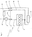
- Fig. 1 shows a schematic representation of an exhaust gas recirculation (EGR) system 1 with an internal combustion engine 2, which is designed as a diesel engine.
- the exhaust gas of the diesel engine 2 enters an exhaust pipe 3, in which an exhaust gas turbine 4 and a device 5 for exhaust gas purification, which a Not shown oxidation catalyst and a particulate filter, are arranged.
- the diesel engine 2 is supplied via an intake 6 compressed and cooled fresh air.
- a charge air compressor 7 and - downstream of - a charge air cooler 8 are arranged.
- the intercooler 8 is - as known from the prior art - designed as aluminum heat exchanger, ie it has in particular of the charge air through-flow, not shown, aluminum pipes and headers made of an aluminum alloy.
- the cooled charge air passes directly into the intake of the diesel engine 2.
- the exhaust gas flow is taken from an exhaust gas recirculation stream, which is returned to the intake of the diesel engine 2 via an EGR line 10, wherein a mixture with the cooled charge air stream takes place in the merger point 11.
- an exhaust gas cooler 12 is arranged, which (which is not shown) is preferably cooled by the coolant of the diesel engine 2.
- an exhaust gas compressor 13 is arranged, which is arranged on the same shaft 14 shown in dashed lines as the charge air compressor 7 and is driven by the exhaust gas turbine 4.
- Both compressors, the charge air compressor 7 and the exhaust gas compressor 13, are preferably arranged in a common compressor housing, not shown, and are sealed against each other, preferably by a arranged on the common shaft 14, not shown, shaft seal. As a result, the exhaust gas flow and fresh air flow are separated from one another and leakage of acidic condensate in the exhaust gas is prevented.
- the cooled and compressed exhaust gas flow bypasses the intercooler 8 and is added to the compressed charge air only downstream of the intercooler 8 at the merger point 11.
- the intercooler 8 is not acted upon by recirculated exhaust gas and thus not by any acid condensate contained in the exhaust gas, which would cause corrosion in the aluminum intercooler 8.
- the exhaust gas compressor 13 is adapted to the exhaust gas recirculation rate, ie to the desired mass flow, while the charge air compressor 7 to be conveyed Fresh air flow for the diesel engine 2 is designed.
- the exhaust gas compressor 13 can be designed in principle more compact than the charge air compressor 7, since the recirculated exhaust gas mass flow is only about 20 to 30% of the total mass flow.
- Fig. 2 shows another embodiment of the invention, an EGR system 15 with two-stage exhaust gas cooling - like parts use like reference numerals.
- the exhaust gas is also taken from the low pressure side at the branch point 9 and returned to the merger point 11 via the EGR passage 10.
- a second exhaust gas cooler 16 is arranged, in which the exhaust gas is further cooled, ie to a lower temperature level.
- the cooling can - as in the exhaust gas cooler 12 - also take place here via the coolant from the cooling circuit of the diesel engine 2, not shown, but possibly also by ambient air.
- the second exhaust gas cooler allows emissions in the exhaust gas stream to be reduced even further.
Landscapes
- Engineering & Computer Science (AREA)
- Chemical & Material Sciences (AREA)
- Combustion & Propulsion (AREA)
- Mechanical Engineering (AREA)
- General Engineering & Computer Science (AREA)
- Exhaust-Gas Circulating Devices (AREA)
Abstract
Description
- Die Erfindung betrifft eine Vorrichtung zur gekühlten Rückführung von Abgas einer Brennkraftmaschine eines Kraftfahrzeuges nach dem Oberbegriff des Patentanspruches 1 - bekannt durch die
EP 1 203 148 B1 . - Die Abgasrückführung (Abkürzung: AGR), insbesondere die gekühlte Abgasrückführung wird in heutigen Fahrzeugen aufgrund gesetzlicher Bestimmungen eingesetzt, um die Partikel- und Schadstoff-, insbesondere Stickoxidemissionen zu senken. Da die Anforderungen an die Abgasreinhaltung strenger werden, sind größere Abgasmassenströme erforderlich, die mit den bekannten AGR-Systemen nur bedingt zu beherrschen sind.
- Bekannte AGR-Systeme sind auf der Hochdruckseite des Verbrennungsmotors angeordnet, wie z. B. in der
US 6,244,256 B1 beschrieben. Das bekannte AGR-System weist einen Abgasturbolader für einen Dieselmotor und eine AGR-Leitung mit einem AGR-Ventil auf, welches zwischen Motor und Abgasturbine angeordnet ist. Das rückgeführte Abgas wird vorzugsweise in zwei Stufen, d. h. in zwei Abgaswärmeübertragem gekühlt, welche jeweils durch einen gesonderten Kühlmittelkreislauf gekühlt werden und als Hochtemperatur- und Niedertemperatur-Abgaskühler ausgebildet sind. Das gekühlte, rückgeführte Abgas wird mit verdichteter und gekühlter Ladeluft zusammengeführt und dem Ansaugtrakt des Motors zugeführt. - Abgaswärmeübertrager, insbesondere Abgaskühler sind in verschiedenen Ausführungsformen bekannt: Durch die
DE 199 07 163 A1 der Anmelderin wurde eine in Edelstahl ausgeführte Schweißkonstruktion für einen Abgaswärmeübertrager bekannt, welcher aus einem Bündel von Abgasrohren besteht, die auf ihrer Außenseite von Kühlmittel umströmt werden, welches dem Kühlkreislauf der Brennkraftmaschine entnommen wird. - Durch die
EP 1 203 148 B1 , von der die Erfindung ausgeht, wurde ein AGR-System für Dieselmotoren bekannt, bei welchem der rückgeführte Abgasstrom hinter einer Abgasturbine, d. h. auf der Niederdruckseite entnommen, gekühlt und dem Frischluft- bzw. Ansaugluftstrom zugeführt wird. Über einen Verdichter gelangt das Gemisch aus Abgas und Frischluft in einen Ladeluftkühler und wird danach dem Ansaugbereich des Dieselmotors zugeführt. - Nachteilig bei den bekannten AGR-Systemen ist, dass bei der Kühlung des rückgeführten Abgases ein saures Kondensat ausfällt, welches beim Durchströmen eines nachgeschalteten Aluminiumwärmeübertragers, insbesondere eines Ladeluftkühlers, zu Korrosionsschäden führen kann. Dieses Problem tritt insbesondere bei einer Entnahme des AGR-Massenstromes auf der Niederdruckseite der Abgasturbine auf.
- Es ist Aufgabe der vorliegenden Erfindung, bei einer Vorrichtung zur gekühlten Abgasrückführung der eingangs genannten Art Korrosionsschäden in vom Abgas beaufschlagten Wärmeübertragern zu verhindern. Diese Aufgabe wird durch die Merkmale des Patentanspruches 1 gelöst. Erfindungsgemäß ist eine getrennte Verdichtung der angesaugten Verbrennungsluft einerseits und des rückgeführten gekühlten Abgases andererseits vorgesehen. Erfindungsgemäß wird dies durch zwei separate Verdichter, einen Frischluft- oder Ladeluftverdichter und einen Abgasverdichter erreicht, die vorzugsweise auf einer Welle angeordnet sind, welche von der Abgasturbine angetrieben wird. Damit wird der Vorteil erreicht, dass das gekühlte und verdichtete Abgas, in welchem sich möglicherweise saures Kondensat befindet, direkt der Brennkraftmaschine zugeführt wird, indem der aus Aluminiumwerkstoffen hergestellte Ladeluftkühler umgangen wird. Letzterer wird somit nur von "reiner" durch den Ladeluftverdichter komprimierter Frischluft beaufschlagt.
- Eine Korrosion des Aluminiumwärmeübertragers wird somit vermieden. Vorteilhaft bei der erfindungsgemäßen Lösung ist auch, dass kein separater Kondensatabscheider für das im Abgas enthaltene saure Kondensat erforderlich ist.
- Nach einer vorteilhaften Ausgestaltung der Erfindung sind beide Verdichter auf einer Welle, vorzugsweise in einem gemeinsamen Verdichtergehäuse angeordnet und untereinander durch ein geeignetes Dichtorgan, vorzugsweise einen Wellendichtring derart gegeneinander abgedichtet, dass sich der Abgasstrom nicht mit dem Frischluftstrom mischen bzw. kein Kondensat in den Bereich des Ladeluftverdichters fließen kann. Damit wird eine saubere Trennung beider Gasströme sichergestellt und eine Korrosion im Aluminiumwärmeübertrager bzw. Ladeluftkühler verhindert.
- Nach einer weiteren vorteilhaften Ausgestaltung der Erfindung ist eine zweistufige Abgaskühlung vorgesehen, d. h. stromabwärts des Abgasverdichters ist ein weiterer Abgaskühler angeordnet, welcher das Abgas auf eine niedrigere Temperatur bringt, was zu einer weiteren Absenkung der Emissionswerte im Abgas führt. Die beiden Abgaskühler können - wie aus dem Stand der Technik bekannt ist - durch eine Flüssigkeit, vorzugsweise das Kühlmittel des Kühlmittelkreislaufes der Brennkraftmaschine oder durch Umgebungsluft gekühlt werden. Aus Korrosionsgründen sind die Abgaskühler - wie ebenfalls aus dem Stand der Technik bekannt - vorzugsweise aus Edelstahl hergestellt.
- Ausführungsbeispiele der Erfindung sind in der Zeichnung dargestellt und werden im Folgenden näher erläutert. Es zeigen
- Fig. 1
- ein erfindungsgemäßes AGR-System mit zwei Verdichtern und
- Fig. 2
- das erfindungsgemäße AGR-System mit zweistufiger Abgaskühlung.
- Fig. 1 zeigt in schematischer Darstellung ein Abgasrückführ (AGR)-System 1 mit einer Brennkraftmaschine 2, welche als Dieselmotor ausgebildet ist. Das Abgas des Dieselmotors 2 gelangt in eine Abgasleitung 3, in welcher eine Abgasturbine 4 sowie eine Vorrichtung 5 zur Abgasreinigung, welche einen nicht dargestellten Oxidationskatalysator sowie ein Partikelfilter aufweist, angeordnet sind. Dem Dieselmotor 2 wird über einen Ansaugtrakt 6 verdichtete und gekühlte Frischluft zugeführt. In dem Ansaugtrakt 6 sind daher ein Ladeluftverdichter 7 und - dem nachgeschaltet - ein Ladeluftkühler 8 angeordnet. Der Ladeluftkühler 8 ist - wie aus dem Stand der Technik bekannt - als Aluminiumwärmeübertrager ausgebildet, d. h. er weist insbesondere von der Ladeluft durchströmbare, nicht dargestellte Aluminiumrohre und Sammelkästen aus einer Aluminiumlegierung auf. Nach Passieren des Ladeluftkühlers 8 gelangt die gekühlte Ladeluft direkt in den Ansaugbereich des Dieselmotors 2. In Strömungsrichtung hinter der Abgasturbine 4, an einem Entnahmepunkt 9, in welchem auch ein nicht dargestelltes AGR-Ventil angeordnet sein kann, wird dem Abgasstrom ein Abgasrückführstrom entnommen, welcher über eine AGR-Leitung 10 dem Ansaugbereich des Dieselmotors 2 wieder zugeführt wird, wobei eine Mischung mit dem gekühlten Ladeluftstrom im Vereinigungspunkt 11 erfolgt. In der AGR-Leitung ist ein Abgaskühler 12 angeordnet, welcher (was nicht dargestellt ist) vorzugsweise durch das Kühlmittel des Dieselmotors 2 gekühlt wird. Stromabwärts vom Abgaskühler 12 ist ein zusätzlicher Verdichter, ein Abgasverdichter 13 angeordnet, welcher auf derselben, gestrichelt dargestellten Welle 14 wie der Ladeluftverdichter 7 angeordnet ist und von der Abgasturbine 4 angetrieben wird. Beide Verdichter, der Ladeluftverdichter 7 und der Abgasverdichter 13, sind vorzugsweise in einem gemeinsamen, nicht dargestellten Verdichtergehäuse angeordnet und sind gegeneinander abgedichtet, vorzugsweise durch einen auf der gemeinsamen Welle 14 angeordneten, nicht dargestellten Wellendichtring. Dadurch werden Abgasstrom und Frischluftstrom voneinander getrennt und ein Durchsickern von saurem Kondensat im Abgas verhindert.
- Wie aus dem Schema ersichtlich, umgeht der gekühlte und verdichtete Abgasstrom den Ladeluftkühler 8 und wird der verdichteten Ladeluft erst stromabwärts des Ladeluftkühlers 8 im Vereinigungspunkt 11 zugemischt. Damit wird der Ladeluftkühler 8 nicht von rückgeführtem Abgas beaufschlagt und somit auch nicht von etwaigem im Abgas enthaltenen sauren Kondensat, welches eine Korrosion im Aluminiumladeluftkühler 8 hervorrufen würde. Der Abgasverdichter 13 ist an die Abgasrückführrate, d. h. an den gewünschten Massenstrom angepasst, während der Ladeluftverdichter 7 an den zu fördernden Frischluftstrom für den Dieselmotor 2 ausgelegt ist. Der Abgasverdichter 13 kann grundsätzlich kompakter als der Ladeluftverdichter 7 ausgelegt werden, da der rückgeführte Abgasmassenstrom nur etwa 20 bis 30 % des gesamten Massenstromes beträgt.
- Fig. 2 zeigt ein weiteres Ausführungsbeispiel der Erfindung, und zwar ein AGR-System 15 mit zweistufiger Abgaskühlung - für gleiche Teile werden gleiche Bezugszahlen verwendet. Das Abgas wird ebenfalls auf der Niederdruckseite an dem Verzweigungspunkt 9 entnommen und über die AGR-Leitung 10 zum Vereinigungspunkt 11 zurückgeführt. Zusätzlich zu dem ersten Abgaskühler 12 ist stromabwärts des Abgasverdichters 13 ein zweiter Abgaskühler 16 angeordnet, in welchem das Abgas weiter abkühlbar ist, d. h. auf ein niedrigeres Temperatumiveau. Die Kühlung kann - wie beim Abgaskühler 12 - auch hier über das Kühlmittel aus dem nicht dargestellten Kühlkreislauf des Dieselmotors 2 erfolgen, möglicherweise jedoch auch durch Umgebungsluft. Durch den zweiten Abgaskühler lassen sich die Emissionen im Abgasstrom noch weiter absenken.
Claims (6)
- Vorrichtung zur gekühlten Rückführung von Abgas einer Brennkraftmaschine (2) eines Kraftfahrzeuges, wobei der Brennkraftmaschine (2) ein Ansaugtrakt (6) und ein Abgastrakt (3) sowie eine Abgasrückführ(AGR)-Leitung (10) mit Abgaskühler (12) zugeordnet sind, wobei im Abgastrakt (3) eine Abgasturbine (4) und im Ansaugtrakt (6) ein Ladeluftverdichter (7) sowie ein Ladeluftkühler (8) angeordnet sind und wobei der Abgasstrom auf der Niederdruckseite (9) der Abgasturbine (4) entnehmbar ist, dadurch gekennzeichnet, dass in der AGR-Leitung (10) ein Abgasverdichter (13) angeordnet ist, durch welchen der rückgeführte Abgasstrom dem Ansaugtrakt stromabwärts des Ladeluftkühlers (8) zuführbar ist.
- Vorrichtung nach Anspruch 1, dadurch gekennzeichnet, dass der Abgasverdichter (13) von der Abgasturbine (4) antreibbar ist.
- Vorrichtung nach Anspruch 2, dadurch gekennzeichnet, dass der Ladeluftverdichter (7) und der Abgasverdichter (13) auf einer gemeinsamen Welle (14) angeordnet sind.
- Vorrichtung nach Anspruch 3, dadurch gekennzeichnet, dass zwischen dem Abgasverdichter (13) und dem Ladeluftverdichter (7) ein Dichtorgan, vorzugsweise ein Wellendichtring zur Trennung des vom Ladeluftverdichter (7) geförderten Ladeluftstroms und des vom Abgasverdichter (13) geförderten Abgasstromes angeordnet ist.
- Vorrichtung nach einem der Ansprüche 1 bis 4, dadurch gekennzeichnet, dass in der AGR-Leitung (10) ein zweiter Abgaskühler (16) angeordnet ist, vorzugsweise in Strömungsrichtung hinter dem Abgasverdichter (13).
- Vorrichtung nach einem der Ansprüche 1 bis 5, dadurch gekennzeichnet, dass der erste und/oder der zweite Abgaskühler (12, 16) durch Luft und/oder eine Flüssigkeit, vorzugsweise das Kühlmittel eines Kühlkreislaufes der Brennkraftmaschine kühlbar sind.
Applications Claiming Priority (1)
| Application Number | Priority Date | Filing Date | Title |
|---|---|---|---|
| DE102005017905A DE102005017905A1 (de) | 2005-04-18 | 2005-04-18 | Vorrichtung zur gekühlten Rückführung von Abgas einer Brennkraftmaschine eines Kraftfahrzeuges |
Publications (1)
| Publication Number | Publication Date |
|---|---|
| EP1731748A1 true EP1731748A1 (de) | 2006-12-13 |
Family
ID=37055507
Family Applications (1)
| Application Number | Title | Priority Date | Filing Date |
|---|---|---|---|
| EP06005344A Withdrawn EP1731748A1 (de) | 2005-04-18 | 2006-03-16 | Vorrichtung zur gekühlten Rückführung von Abgas einer Brennkraftmaschine eines Kraftfahrzeuges |
Country Status (3)
| Country | Link |
|---|---|
| US (1) | US20060248888A1 (de) |
| EP (1) | EP1731748A1 (de) |
| DE (1) | DE102005017905A1 (de) |
Families Citing this family (79)
| Publication number | Priority date | Publication date | Assignee | Title |
|---|---|---|---|---|
| DE102008000852A1 (de) * | 2008-03-27 | 2009-10-01 | Bosch Mahle Turbo Systems Gmbh & Co. Kg | Abgasturbolader für ein Kraftfahrzeug |
| CA2718803C (en) | 2008-03-28 | 2016-07-12 | Exxonmobil Upstream Research Company | Low emission power generation and hydrocarbon recovery systems and methods |
| MY156350A (en) | 2008-03-28 | 2016-02-15 | Exxonmobil Upstream Res Co | Low emission power generation and hydrocarbon recovery systems and methods |
| DE102008050368A1 (de) | 2008-10-02 | 2010-04-08 | Deutz Ag | Zweistufig gekühltes Abgasrückführsystem |
| PL2344738T3 (pl) | 2008-10-14 | 2019-09-30 | Exxonmobil Upstream Research Company | Sposób i układ do sterowania produktami spalania |
| WO2010072227A1 (de) * | 2008-12-22 | 2010-07-01 | Fev Motorentechnik Gmbh | Abgasrückführungssystem und verfahren zur abgasrückführung |
| US8307646B2 (en) * | 2009-08-04 | 2012-11-13 | International Engine Intellectual Property Company, Llc | System using supplemental compressor for EGR |
| CA2777768C (en) | 2009-11-12 | 2016-06-07 | Exxonmobil Upstream Research Company | Low emission power generation and hydrocarbon recovery systems and methods |
| DE102010003002B4 (de) | 2010-03-18 | 2018-10-31 | Man Diesel & Turbo Se | Abgasturbolader-Anordnung mit Abgasrückführeinrichtung und Abgasverdichter |
| DE102010030499A1 (de) | 2010-06-24 | 2011-12-29 | Man Diesel & Turbo Se | Zylinderkopf und damit ausgerüstete Brennkraftmaschine |
| CN102959202B (zh) | 2010-07-02 | 2016-08-03 | 埃克森美孚上游研究公司 | 集成系统、发电的方法和联合循环发电系统 |
| US9903271B2 (en) | 2010-07-02 | 2018-02-27 | Exxonmobil Upstream Research Company | Low emission triple-cycle power generation and CO2 separation systems and methods |
| CA2801499C (en) | 2010-07-02 | 2017-01-03 | Exxonmobil Upstream Research Company | Low emission power generation systems and methods |
| JP5906555B2 (ja) | 2010-07-02 | 2016-04-20 | エクソンモービル アップストリーム リサーチ カンパニー | 排ガス再循環方式によるリッチエアの化学量論的燃焼 |
| TWI593872B (zh) | 2011-03-22 | 2017-08-01 | 艾克頌美孚上游研究公司 | 整合系統及產生動力之方法 |
| TWI563166B (en) | 2011-03-22 | 2016-12-21 | Exxonmobil Upstream Res Co | Integrated generation systems and methods for generating power |
| TWI564474B (zh) | 2011-03-22 | 2017-01-01 | 艾克頌美孚上游研究公司 | 於渦輪系統中控制化學計量燃燒的整合系統和使用彼之產生動力的方法 |
| TWI563165B (en) | 2011-03-22 | 2016-12-21 | Exxonmobil Upstream Res Co | Power generation system and method for generating power |
| US8746217B2 (en) | 2011-10-07 | 2014-06-10 | Deere & Company | Power system comprising an air cooled HT EGR cooler and LT EGR cooler |
| WO2013095829A2 (en) | 2011-12-20 | 2013-06-27 | Exxonmobil Upstream Research Company | Enhanced coal-bed methane production |
| US9353682B2 (en) | 2012-04-12 | 2016-05-31 | General Electric Company | Methods, systems and apparatus relating to combustion turbine power plants with exhaust gas recirculation |
| US10273880B2 (en) | 2012-04-26 | 2019-04-30 | General Electric Company | System and method of recirculating exhaust gas for use in a plurality of flow paths in a gas turbine engine |
| US9784185B2 (en) | 2012-04-26 | 2017-10-10 | General Electric Company | System and method for cooling a gas turbine with an exhaust gas provided by the gas turbine |
| US10215412B2 (en) | 2012-11-02 | 2019-02-26 | General Electric Company | System and method for load control with diffusion combustion in a stoichiometric exhaust gas recirculation gas turbine system |
| US9803865B2 (en) | 2012-12-28 | 2017-10-31 | General Electric Company | System and method for a turbine combustor |
| US10107495B2 (en) | 2012-11-02 | 2018-10-23 | General Electric Company | Gas turbine combustor control system for stoichiometric combustion in the presence of a diluent |
| US9631815B2 (en) | 2012-12-28 | 2017-04-25 | General Electric Company | System and method for a turbine combustor |
| US9574496B2 (en) | 2012-12-28 | 2017-02-21 | General Electric Company | System and method for a turbine combustor |
| US9611756B2 (en) | 2012-11-02 | 2017-04-04 | General Electric Company | System and method for protecting components in a gas turbine engine with exhaust gas recirculation |
| US10161312B2 (en) | 2012-11-02 | 2018-12-25 | General Electric Company | System and method for diffusion combustion with fuel-diluent mixing in a stoichiometric exhaust gas recirculation gas turbine system |
| US9869279B2 (en) | 2012-11-02 | 2018-01-16 | General Electric Company | System and method for a multi-wall turbine combustor |
| US9599070B2 (en) | 2012-11-02 | 2017-03-21 | General Electric Company | System and method for oxidant compression in a stoichiometric exhaust gas recirculation gas turbine system |
| US9708977B2 (en) | 2012-12-28 | 2017-07-18 | General Electric Company | System and method for reheat in gas turbine with exhaust gas recirculation |
| US10208677B2 (en) | 2012-12-31 | 2019-02-19 | General Electric Company | Gas turbine load control system |
| US9581081B2 (en) | 2013-01-13 | 2017-02-28 | General Electric Company | System and method for protecting components in a gas turbine engine with exhaust gas recirculation |
| US9512759B2 (en) | 2013-02-06 | 2016-12-06 | General Electric Company | System and method for catalyst heat utilization for gas turbine with exhaust gas recirculation |
| TW201502356A (zh) | 2013-02-21 | 2015-01-16 | Exxonmobil Upstream Res Co | 氣渦輪機排氣中氧之減少 |
| US9938861B2 (en) | 2013-02-21 | 2018-04-10 | Exxonmobil Upstream Research Company | Fuel combusting method |
| RU2637609C2 (ru) | 2013-02-28 | 2017-12-05 | Эксонмобил Апстрим Рисерч Компани | Система и способ для камеры сгорания турбины |
| US9618261B2 (en) | 2013-03-08 | 2017-04-11 | Exxonmobil Upstream Research Company | Power generation and LNG production |
| US20140250945A1 (en) | 2013-03-08 | 2014-09-11 | Richard A. Huntington | Carbon Dioxide Recovery |
| JP6143895B2 (ja) | 2013-03-08 | 2017-06-07 | エクソンモービル アップストリーム リサーチ カンパニー | 発電及びメタンハイドレートからのメタン回収 |
| TW201500635A (zh) | 2013-03-08 | 2015-01-01 | Exxonmobil Upstream Res Co | 處理廢氣以供用於提高油回收 |
| US9631542B2 (en) | 2013-06-28 | 2017-04-25 | General Electric Company | System and method for exhausting combustion gases from gas turbine engines |
| TWI654368B (zh) | 2013-06-28 | 2019-03-21 | 美商艾克頌美孚上游研究公司 | 用於控制在廢氣再循環氣渦輪機系統中的廢氣流之系統、方法與媒體 |
| US9617914B2 (en) | 2013-06-28 | 2017-04-11 | General Electric Company | Systems and methods for monitoring gas turbine systems having exhaust gas recirculation |
| US9835089B2 (en) | 2013-06-28 | 2017-12-05 | General Electric Company | System and method for a fuel nozzle |
| US9587510B2 (en) | 2013-07-30 | 2017-03-07 | General Electric Company | System and method for a gas turbine engine sensor |
| US9903588B2 (en) | 2013-07-30 | 2018-02-27 | General Electric Company | System and method for barrier in passage of combustor of gas turbine engine with exhaust gas recirculation |
| US9951658B2 (en) | 2013-07-31 | 2018-04-24 | General Electric Company | System and method for an oxidant heating system |
| US10030588B2 (en) | 2013-12-04 | 2018-07-24 | General Electric Company | Gas turbine combustor diagnostic system and method |
| US9752458B2 (en) | 2013-12-04 | 2017-09-05 | General Electric Company | System and method for a gas turbine engine |
| JP2015124663A (ja) * | 2013-12-26 | 2015-07-06 | トヨタ自動車株式会社 | 内燃機関 |
| US10227920B2 (en) | 2014-01-15 | 2019-03-12 | General Electric Company | Gas turbine oxidant separation system |
| US9863267B2 (en) | 2014-01-21 | 2018-01-09 | General Electric Company | System and method of control for a gas turbine engine |
| US9915200B2 (en) | 2014-01-21 | 2018-03-13 | General Electric Company | System and method for controlling the combustion process in a gas turbine operating with exhaust gas recirculation |
| US10079564B2 (en) | 2014-01-27 | 2018-09-18 | General Electric Company | System and method for a stoichiometric exhaust gas recirculation gas turbine system |
| US10047633B2 (en) | 2014-05-16 | 2018-08-14 | General Electric Company | Bearing housing |
| US9885290B2 (en) | 2014-06-30 | 2018-02-06 | General Electric Company | Erosion suppression system and method in an exhaust gas recirculation gas turbine system |
| US10060359B2 (en) | 2014-06-30 | 2018-08-28 | General Electric Company | Method and system for combustion control for gas turbine system with exhaust gas recirculation |
| US10655542B2 (en) | 2014-06-30 | 2020-05-19 | General Electric Company | Method and system for startup of gas turbine system drive trains with exhaust gas recirculation |
| US9556792B2 (en) | 2014-10-17 | 2017-01-31 | Kohler, Co. | Dual compressor turbocharger |
| US10378549B2 (en) | 2014-10-17 | 2019-08-13 | Kohler Co. | Dual compressor turbocharger |
| US9819292B2 (en) | 2014-12-31 | 2017-11-14 | General Electric Company | Systems and methods to respond to grid overfrequency events for a stoichiometric exhaust recirculation gas turbine |
| US9869247B2 (en) | 2014-12-31 | 2018-01-16 | General Electric Company | Systems and methods of estimating a combustion equivalence ratio in a gas turbine with exhaust gas recirculation |
| US10788212B2 (en) | 2015-01-12 | 2020-09-29 | General Electric Company | System and method for an oxidant passageway in a gas turbine system with exhaust gas recirculation |
| US10253690B2 (en) | 2015-02-04 | 2019-04-09 | General Electric Company | Turbine system with exhaust gas recirculation, separation and extraction |
| US10316746B2 (en) | 2015-02-04 | 2019-06-11 | General Electric Company | Turbine system with exhaust gas recirculation, separation and extraction |
| US10094566B2 (en) | 2015-02-04 | 2018-10-09 | General Electric Company | Systems and methods for high volumetric oxidant flow in gas turbine engine with exhaust gas recirculation |
| US10267270B2 (en) | 2015-02-06 | 2019-04-23 | General Electric Company | Systems and methods for carbon black production with a gas turbine engine having exhaust gas recirculation |
| US10145269B2 (en) | 2015-03-04 | 2018-12-04 | General Electric Company | System and method for cooling discharge flow |
| US10480792B2 (en) | 2015-03-06 | 2019-11-19 | General Electric Company | Fuel staging in a gas turbine engine |
| US9726121B2 (en) | 2015-03-31 | 2017-08-08 | Electro-Motive Diesel, Inc. | Engine system having reduced pressure EGR system |
| US9664148B2 (en) | 2015-03-31 | 2017-05-30 | Electro-Motive Diesel, Inc. | Engine system having increased pressure EGR system |
| DE102015207791B4 (de) | 2015-04-28 | 2018-11-15 | Ford Global Technologies, Llc | Kraftfahrzeug |
| CN106762246A (zh) * | 2016-12-21 | 2017-05-31 | 东风商用车有限公司 | 一种egr涡轮增压系统 |
| GB2564691B (en) * | 2017-07-20 | 2019-08-14 | Ford Global Tech Llc | An EGR system having a turbine driven auxiliary compressor |
| WO2019115825A1 (en) * | 2017-12-15 | 2019-06-20 | Eaton Intelligent Power Limited | Egr pump and supercharger for two stroke engine |
| KR20240161789A (ko) * | 2021-11-02 | 2024-11-12 | 차트 에너지 앤드 케미칼즈 인코포레이티드 | 배기가스 재순환 기능을 갖는 탄소 포집 시스템 및 방법 |
Citations (6)
| Publication number | Priority date | Publication date | Assignee | Title |
|---|---|---|---|---|
| DE19728353C1 (de) * | 1997-07-03 | 1998-09-24 | Daimler Benz Ag | Brennkraftmaschine mit einem Abgasturbolader |
| DE19907163A1 (de) | 1998-04-24 | 1999-10-28 | Behr Gmbh & Co | Wärmetauscher, insbesondere Abgaswärmetauscher |
| US6145313A (en) * | 1997-03-03 | 2000-11-14 | Allied Signal Inc. | Turbocharger incorporating an integral pump for exhaust gas recirculation |
| US6164071A (en) * | 1997-09-08 | 2000-12-26 | Cummins Engine Company, Inc. | EGR delivery and control system using dedicated full authority compressor |
| US6244256B1 (en) | 1999-10-07 | 2001-06-12 | Behr Gmbh & Co. | High-temperature coolant loop for cooled exhaust gas recirculation for internal combustion engines |
| EP1203148B1 (de) | 1999-06-15 | 2004-10-06 | Johnson Matthey Public Limited Company | Verbesserungen in der schadstoffausstossregelung |
Family Cites Families (11)
| Publication number | Priority date | Publication date | Assignee | Title |
|---|---|---|---|---|
| US6295809B1 (en) * | 1999-07-12 | 2001-10-02 | Ford Global Technologies, Inc. | Emission control system with a catalyst |
| US6301888B1 (en) * | 1999-07-22 | 2001-10-16 | The United States Of America As Represented By The Administrator Of The Environmental Protection Agency | Low emission, diesel-cycle engine |
| US6351946B1 (en) * | 1999-09-27 | 2002-03-05 | Caterpillar Inc. | Exhaust gas recirculation system in an internal combustion engine |
| GB0018406D0 (en) * | 2000-07-28 | 2000-09-13 | Serck Heat Transfer Limited | EGR bypass tube cooler |
| US6374612B1 (en) * | 2000-09-21 | 2002-04-23 | Caterpillar Inc. | Interstage cooling of a multi-compressor turbocharger |
| US20030154716A1 (en) * | 2002-02-21 | 2003-08-21 | Detroit Diesel Corporation | Exhaust gas recirculation system |
| DE10232515A1 (de) * | 2002-07-18 | 2004-04-08 | Daimlerchrysler Ag | Abgasrückführung einer Brennkraftmaschine |
| US6701707B1 (en) * | 2002-09-04 | 2004-03-09 | Ford Global Technologies, Llc | Exhaust emission diagnostics |
| US6993900B2 (en) * | 2002-10-21 | 2006-02-07 | Ford Global Technologies, Llc | Exhaust gas aftertreatment systems |
| US6805108B2 (en) * | 2002-12-20 | 2004-10-19 | Caterpillar Inc | Heat exchanger for a supercharger |
| US7013879B2 (en) * | 2003-11-17 | 2006-03-21 | Honeywell International, Inc. | Dual and hybrid EGR systems for use with turbocharged engine |
-
2005
- 2005-04-18 DE DE102005017905A patent/DE102005017905A1/de not_active Withdrawn
-
2006
- 2006-03-16 EP EP06005344A patent/EP1731748A1/de not_active Withdrawn
- 2006-04-18 US US11/405,700 patent/US20060248888A1/en not_active Abandoned
Patent Citations (6)
| Publication number | Priority date | Publication date | Assignee | Title |
|---|---|---|---|---|
| US6145313A (en) * | 1997-03-03 | 2000-11-14 | Allied Signal Inc. | Turbocharger incorporating an integral pump for exhaust gas recirculation |
| DE19728353C1 (de) * | 1997-07-03 | 1998-09-24 | Daimler Benz Ag | Brennkraftmaschine mit einem Abgasturbolader |
| US6164071A (en) * | 1997-09-08 | 2000-12-26 | Cummins Engine Company, Inc. | EGR delivery and control system using dedicated full authority compressor |
| DE19907163A1 (de) | 1998-04-24 | 1999-10-28 | Behr Gmbh & Co | Wärmetauscher, insbesondere Abgaswärmetauscher |
| EP1203148B1 (de) | 1999-06-15 | 2004-10-06 | Johnson Matthey Public Limited Company | Verbesserungen in der schadstoffausstossregelung |
| US6244256B1 (en) | 1999-10-07 | 2001-06-12 | Behr Gmbh & Co. | High-temperature coolant loop for cooled exhaust gas recirculation for internal combustion engines |
Also Published As
| Publication number | Publication date |
|---|---|
| US20060248888A1 (en) | 2006-11-09 |
| DE102005017905A1 (de) | 2006-10-19 |
Similar Documents
| Publication | Publication Date | Title |
|---|---|---|
| DE102005017905A1 (de) | Vorrichtung zur gekühlten Rückführung von Abgas einer Brennkraftmaschine eines Kraftfahrzeuges | |
| EP1899595B1 (de) | Vorrichtung zur rückführung und kühlung von abgas für eine brennkraftmaschine | |
| DE4240239C2 (de) | Verbrennungskraftmaschine | |
| DE102014206644B4 (de) | Aufgeladene Brennkraftmaschine und Verfahren zum Betreiben einer derartigen Brennkraftmaschine | |
| EP2161438B1 (de) | System zur Rückführung von Abgas einer Verbrennungskraftmaschine und Verfahren zur Rückführung von Abgas einer Verbrennungskraftmaschine | |
| EP1937957A1 (de) | Anordnung zur rückführung und kühlung von abgas einer brennkraftmaschine | |
| EP2302190B1 (de) | Abgasrückführsystem | |
| DE19938292A1 (de) | Vorrichtung zur Befeuchtung der Einlaßluft von Brennkraftmaschinen mit Turbolader | |
| EP1664519B1 (de) | Abgaswärmeüberträger, insbesondere abgaskühler für abgasrückführung in kraftfahrzeugen | |
| DE102017118455B4 (de) | Abgasnachbehandlungssystem für einen Verbrennungsmotor und Verfahren zur Abgasnachbehandlung eines Verbrennungsmotors | |
| DE102008045479A1 (de) | System zur Rückführung von Abgas einer Verbrennungskraftmaschine und Verfahren zur Rückführung von Abgas einer Verbrennungskraftmaschine | |
| DE102019206448A1 (de) | Motorsystem | |
| DE102013206690A1 (de) | Brennkraftmaschine mit Ladeluftkühler und Abgasrückführung und Verfahren zum Herstellen einer derartigen Brennkraftmaschine | |
| EP3385520B1 (de) | Abgasnachbehandlungsvorrichtung für einen verbrennungsmotor | |
| EP1843033B1 (de) | Abgasanlage einer Brennkraftmaschine für ein Kraftfahrzeug mit Abgasrückführung | |
| DE102008046938A1 (de) | Verfahren zum Betreiben einer Brennkraftmaschine und Brennkraftmaschinenanordnung | |
| WO2010072227A1 (de) | Abgasrückführungssystem und verfahren zur abgasrückführung | |
| EP3428439A1 (de) | Abgasrückführungsanordnung eines kraftfahrzeuges und verfahren zum betrieb einer abgasrückführungsanordnung | |
| EP1957767B1 (de) | Verfahren zur abgasnachbehandlung bei verbrennungsmotoren, und vorrichtung zur durchführung dieses verfahrens | |
| DE102015219625B4 (de) | Aufgeladene Brennkraftmaschine mit Niederdruck-Abgasrückführung und Verfahren zum Betreiben einer derartigen Brennkraftmaschine | |
| DE102004013206B4 (de) | Variable Kühlvorrichtung für zur Saugseite eines aufgeladenen Verbrennungsmotors rückgeführtes Abgas | |
| EP3379069A1 (de) | Verbrennungsmotor und abgasnachbehandlungssystem für einen verbrennungsmotor | |
| DE102019206450A1 (de) | Motorsystem | |
| DE102014216101A1 (de) | Aufgeladene Brennkraftmaschine mit Abgasrückführung und Verfahren zum Betreiben einer derartigen Brennkraftmaschine | |
| DE102015104179B4 (de) | Vorrichtungen zur Rückführung von Abgas eines Verbrennungsmotors in einem Kraftfahrzeug |
Legal Events
| Date | Code | Title | Description |
|---|---|---|---|
| PUAI | Public reference made under article 153(3) epc to a published international application that has entered the european phase |
Free format text: ORIGINAL CODE: 0009012 |
|
| AK | Designated contracting states |
Kind code of ref document: A1 Designated state(s): AT BE BG CH CY CZ DE DK EE ES FI FR GB GR HU IE IS IT LI LT LU LV MC NL PL PT RO SE SI SK TR |
|
| AX | Request for extension of the european patent |
Extension state: AL BA HR MK YU |
|
| 17P | Request for examination filed |
Effective date: 20070519 |
|
| 17Q | First examination report despatched |
Effective date: 20070719 |
|
| AKX | Designation fees paid |
Designated state(s): AT BE BG CH CY CZ DE DK EE ES FI FR GB GR HU IE IS IT LI LT LU LV MC NL PL PT RO SE SI SK TR |
|
| STAA | Information on the status of an ep patent application or granted ep patent |
Free format text: STATUS: THE APPLICATION IS DEEMED TO BE WITHDRAWN |
|
| 18D | Application deemed to be withdrawn |
Effective date: 20141001 |