EP1731069B1 - Salle d'eau adaptée pour la prise d'une douche ou d'un bain - Google Patents
Salle d'eau adaptée pour la prise d'une douche ou d'un bain Download PDFInfo
- Publication number
- EP1731069B1 EP1731069B1 EP06011361A EP06011361A EP1731069B1 EP 1731069 B1 EP1731069 B1 EP 1731069B1 EP 06011361 A EP06011361 A EP 06011361A EP 06011361 A EP06011361 A EP 06011361A EP 1731069 B1 EP1731069 B1 EP 1731069B1
- Authority
- EP
- European Patent Office
- Prior art keywords
- washroom
- bath
- shower
- accessory
- configuration
- Prior art date
- Legal status (The legal status is an assumption and is not a legal conclusion. Google has not performed a legal analysis and makes no representation as to the accuracy of the status listed.)
- Active
Links
Images


Classifications
-
- A—HUMAN NECESSITIES
- A47—FURNITURE; DOMESTIC ARTICLES OR APPLIANCES; COFFEE MILLS; SPICE MILLS; SUCTION CLEANERS IN GENERAL
- A47K—SANITARY EQUIPMENT; ACCESSORIES THEREFOR, e.g. TOILET ACCESSORIES
- A47K4/00—Combinations of baths, showers, sinks, wash-basins, closets, or urinals, not covered by a single other group of this subclass
-
- A—HUMAN NECESSITIES
- A47—FURNITURE; DOMESTIC ARTICLES OR APPLIANCES; COFFEE MILLS; SPICE MILLS; SUCTION CLEANERS IN GENERAL
- A47K—SANITARY EQUIPMENT; ACCESSORIES THEREFOR, e.g. TOILET ACCESSORIES
- A47K3/00—Baths; Showers; Appurtenances therefor
- A47K3/14—Replaceable separating walls for baths
-
- A—HUMAN NECESSITIES
- A47—FURNITURE; DOMESTIC ARTICLES OR APPLIANCES; COFFEE MILLS; SPICE MILLS; SUCTION CLEANERS IN GENERAL
- A47K—SANITARY EQUIPMENT; ACCESSORIES THEREFOR, e.g. TOILET ACCESSORIES
- A47K3/00—Baths; Showers; Appurtenances therefor
- A47K3/20—Baths; Showers; Appurtenances therefor combined with douches
Definitions
- the invention relates to a particular bathroom that we will call bath-shower because of its ability to transform from shower to bathtub and vice versa.
- the document DE19647767 describes a bathtub comprising a removable wall.
- the document W02004034863 The applicant describes a sanitary room comprising a bathroom equipped with an auxiliary element alternatively usable as a bench in a shower configuration or as a water retaining wall in a bathtub configuration.
- a difficulty of this solution consists in sealing this removable bath wall and its resistance to the pressure of the water and the weight of the user who can possibly bear on this wall.
- the object of the present invention is to provide a bath shower transformation device which ensures a good seal, strength and stability of the bath obtained.
- a bathroom adapted for taking a shower which comprises a water inlet and a wastewater outlet, an accessory representing a removable wall of a bathtub, a means of blocking and pressing the outer surface of the accessory in a bathtub wall configuration to ensure its strength and sealing, characterized in that the blocking means is an element occupying a horizontal position on the floor in shower configuration of the bathroom and a substantially vertical position in a bathtub configuration.
- the blocking means may be a grid placed above a wastewater outlet duct in shower configuration, rotatable about an axis to occupy a substantially vertical position in the bath configuration.
- a second grid may be placed under the mobile grid.
- This second grid can occupy permanently a horizontal position in a housing in the upper part of the duct, below the position of the first grid in shower configuration or it can also be rotatable about the same axis and be perpendicular to the first grid so as to occupy a horizontal position above the duct in bath configuration.
- the locking means and pressure of the outer surface of the accessory can occupy a surface at least equal to one third of the outer surface of the accessory.
- It can be rotatable and operable by means of a manual lever, which can occupy two locked stable positions, corresponding to substantially horizontal and vertical positions of said locking means and pressure.
- the figure 1 illustrates an embodiment of a water room 1 according to the invention, whose geometry is similar to an embodiment as described in the document of the prior art W02004034863 but equipped with a device according to the invention.
- this bathroom is in shower position. It is delimited by four side walls 2, 3, 4, 5. Its floor 6 is relatively flat, possibly slightly sloping towards a substantially centered grid 7 of wastewater discharge. For reasons of simplification, the water inlet device is not shown.
- the bathroom is equipped with two lateral consoles 8 respectively disposed against the walls 3, 4 of the bathroom and supported by vertical support elements 9 having a concave surface facing the interior of the room water.
- These vertical supports have a length of about 70 centimeters, less than that of the consoles 8 of length about 90 centimeters, are placed against the wall 2 of the bathroom and end with a vertical wall 10 distant from the end of the brackets 8 by a distance of about 20 centimeters corresponding to the thickness of an accessory 11, for reasons which will appear later.
- This accessory 11 is disposed horizontally and transversely to the bathroom, between the side walls 3, 4, resting on either side of the brackets 8. In this shower position, this accessory 11 thus serves as a bench , the consoles can be used as shelves to place toiletries or even auxiliary bench.
- the figure 3 illustrates these same elements in side view, in the shower position. It will be noted that the drainage duct 13 is closed by two superposed grids 7 and 12, the grid 7 being rotatable about an axis 14 and the grid 12 fixed.
- the figure 4 illustrates the bathroom after transformation from shower to bath.
- the bath consists of the wall 2 of the bathroom, the two rounded surfaces of the support elements 9 consoles 8 and the accessory 11 positioned vertically on its edge to form the fourth missing wall or dike of the bath. It therefore uses three permanent walls to which is added a removable wall, the accessory 11 that we will call bench-bath with reference to its two functions. For reasons of simplification, the water inlet (s) and the siphon (s), used for the shower and / or bath functions, are not shown.
- the upper grill 7 which covers the exhaust duct 13 occupies a second quasi-vertical position in this bath configuration in which the bath-bath 11 is sandwiched between the vertical walls 10 and the grid 7.
- the grid 7 exerts a pressure along the entire length of the outer surface of the bath-bath 11, thus guaranteeing its resistance to the pressures of the bath water and its resistance to any other pressure exerted by a user for example.
- the permanent grid 12 then covers only the conduit 13.
- the width of the bench 11 corresponds to the height of the overflow of a standard bath, between 30 and 40 centimeters, for example, and sits under the surface of the brackets 8 of corresponding height. Its length is the width of the bathroom 1 and the length of a standard bath, about 1.50 meters. Finally, its thickness is about 20 centimeters, which corresponds approximately to the distance between the raised grid 7 and the surface 10, as well as the length of the console 8 protruding from its support element 9.
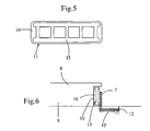
- the figure 5 illustrates a possible structure of the bath-bed 11, which may comprise a rigid frame 15 in the form of a scale surrounded by a more flexible material 16 elastically deformable as a foam.
- the bench-bath has nominal dimensions slightly greater than its housing provided in bath configuration: thus, in this configuration, it is compressed in its three dimensions, height, length and thickness, which is possible thanks to its foam 16 which 'surrounded. This compression further improves the sealing of this removable wall.
- the location of the water discharge conduit 13 at the outer edge of the removable wall of the bath is advantageous since it makes it possible to immediately evacuate any possible water leakage from the bath, as well as the evacuation of the water. escaping from a user when leaving the bath.
- the bath bench 11 in the auxiliary wall position of the bathtub thus fulfills another overflow function, since it allows the evacuation of water when filling above its height.
- FIGS. 7a to 7d illustrate schematically the essential steps of the implementation of the bath shower transformation.
- the bathroom is in shower configuration.
- the evacuation duct is covered by a first grid 7 connected to a second perpendicular grid 12, positioned vertically inside the duct in this configuration.
- the bench-bath 11 is slid to the ends of the consoles 8 and is tilted.
- the grid 7 is pivoted about its axis 14 and holds in abutment a first end of the bath-bench 11 in the tilting position while the second end rests on the brackets 8.
- the bath-bench 11 is pushed until 'to completely leave the consoles 8.
- a manual lever connected to the axis 14 and the grid 7 may be provided along a side wall 3 or 4 of the bathroom.
- means for blocking the vertical position of the grid 7 must be provided, for example in the form of a locking hook of the actuating lever.
- the gate can be locked in an intermediate position such as that represented in FIG. figure 7b .
- a motorized means may be provided to implement these movements.
- the accessory 11 forming the removable wall 11 of the bath may not be a bench, not used in the shower configuration, but simply be placed in a proper storage.
- the rotating grid 7 can be replaced by any other means of similar shape, which can occupy a vertical position allowing it to perform a function of blocking and pressing a large surface of the accessory 11 to oppose at the bath water pressure, ensure a good resistance of the removable wall and guarantee the watertightness of the bath. It may be a board placed on the floor of the shower, shape not necessarily rectangular, not occupying the entire length of the bath.
- the same inventive concept can be implemented with more than one removable wall of the bathtub.
- the solution allows the use of a bathroom to take a conventional shower, which is accessed without having to overcome obstacles. In addition, it also allows to take a bath, standard dimensions, after a simple transformation.
- the removable bathtub dike, placed in bathtub wall position according to the invention therefore makes it possible to guarantee the seal, ensure its resistance and impact stability.
- this solution is hygienic and self-cleaning.
Landscapes
- Health & Medical Sciences (AREA)
- Public Health (AREA)
- Epidemiology (AREA)
- General Health & Medical Sciences (AREA)
- Bathtubs, Showers, And Their Attachments (AREA)
- Residential Or Office Buildings (AREA)
- Devices For Medical Bathing And Washing (AREA)
- Cosmetics (AREA)
Description
- L'invention concerne une salle d'eau particulière que nous appellerons bain-douche du fait de sa capacité de se transformer de douche en baignoire et réciproquement.
- Le document
DE19647767 décrit une baignoire comprenant une paroi amovible. - Le document
W02004034863 du demandeur décrit un local sanitaire comprenant une salle d'eau équipée d'un élément auxiliaire utilisable alternativement comme banquette dans une configuration de douche ou comme paroi de retenue d'eau dans une configuration de baignoire. Une difficulté de cette solution consiste à assurer l'étanchéité de cette paroi amovible de baignoire et sa résistance à la pression de l'eau et au poids de l'utilisateur qui peut éventuellement prendre appui sur cette paroi. - L'objet de la présente invention est de proposer un dispositif de transformation de douche en bain qui assure une bonne étanchéité, résistance et stabilité de la baignoire obtenu.
- L'invention atteint les objets ci-dessus en par une salle d'eau adaptée pour la prise d'une douche qui comprend une arrivée d'eau et une évacuation des eaux usées, un accessoire représentant une paroi amovible de baignoire, un moyen de blocage et de pression de la surface extérieure de l'accessoire dans une configuration de paroi de baignoire afin d'assurer sa résistance et son étanchéité, caractérisée en ce que le moyen de blocage est un élément occupant une_position horizontale sur le sol en configuration de douche de la salle d'eau et une position sensiblement verticale dans une configuration de baignoire.
- Le moyen de blocage peut être une grille placée au-dessus d'un conduit d'évacuation des eaux usées en configuration de douche, mobile en rotation autour d'un axe pour occuper une position sensiblement verticale en configuration de bain.
- Selon une variante de réalisation, une seconde grille peut être placée sous la grille mobile. Cette seconde grille peut occuper en permanence une position horizontale dans un logement dans la partie haute du conduit, au-dessous de la position de la première grille en configuration de douche ou elle peut aussi être mobile en rotation autour du même axe et être perpendiculaire à la première grille de sorte d'occuper une position horizontale au-dessus du conduit en configuration de bain.
- Le moyen de blocage et de pression de la surface extérieure de l'accessoire peut occuper une surface au moins égale au tiers de la surface extérieure de l'accessoire.
- Il peut être mobile en rotation et actionnable à l'aide d'un levier manuel, qui peut occuper deux positions stables verrouillées, correspondant aux positions sensiblement horizontales et verticales dudit moyen de blocage et pression.
- Il peut aussi occuper une position intermédiaire stable, pour faciliter la transformation de douche en bain.
- Enfin, il peut se composer d'une armature rigide entourée d'une partie souple élastiquement déformable.
- Ces objets, caractéristiques et avantages de la présente invention seront exposés en détail dans la description suivante d'un mode d'exécution particulier fait à titre non-limitatif en relation avec les figures jointes parmi lesquelles :
- La
figure 1 représente une salle d'eau selon un mode d'implémentation de l'invention ; - la
figure 2 représente une vue en perspective agrandie du bain-douche de lafigure 1 ; - la
figure 3 représente une vue de côté du bain-douche selon un mode d'implémentation de l'invention en position de douche ; - la
figure 4 représente une vue de côté du bain-douche selon un mode d'implémentation de l'invention en position de bain ; - la
figure 5 représente la structure d'une paroi amovible de bain selon un mode d'implémentation de l'invention ; - la
figure 6 montre en vue de côté cette structure en position de bain ; - les
figures 7a à 7d illustrent les étapes principales de la transformation du bain-douche de la position de douche à celle de bain ; - La
figure 1 illustre un mode de réalisation d'une salle d'eau 1 selon l'invention, dont la géométrie se rapproche d'une réalisation telle que décrite dans le document de l'art antérieurW02004034863 mais équipée d'un dispositif selon l'invention. - Sur la
figure 1 , cette salle d'eau est en position de douche. Elle est délimitée par quatre parois latérales 2, 3, 4, 5. Son sol 6 est relativement plat, éventuellement légèrement en pente vers une grille 7 sensiblement centrée d'évacuation des eaux usées. Pour des raisons de simplification, le dispositif d'arrivée d'eau n'est pas représenté. - Comme cela est mieux illustré en
figure 2 , la salle d'eau est équipée de deux consoles latérales 8 disposées respectivement contre les parois 3, 4 de la salle d'eau et supportées par des éléments de supports verticaux 9 présentant une surface concave orientée vers l'intérieur de la salle d'eau. Ces supports verticaux présentent une longueur d'environ 70 centimètres, inférieure à celle des consoles 8 de longueur environ 90 centimètres, sont placés contre la paroi 2 de la salle d'eau et se terminent par une paroi verticale 10 distante de l'extrémité des consoles 8 d'une distance d'environ 20 centimètres correspondant à l'épaisseur d'un accessoire 11, pour des raisons qui apparaîtront par la suite. Cet accessoire 11 est disposé horizontalement et transversalement à la salle d'eau, entre les parois latérales 3, 4, reposant de part et d'autre sur les consoles 8. Dans cette position de douche, cet accessoire 11 remplit ainsi la fonction de banc, les consoles pouvant servir d'étagères pour placer des produits de toilette, voire de banc auxiliaire. - La
figure 3 illustre ces mêmes éléments en vue de côté, dans la position de douche. On remarque que le conduit d'évacuation des eaux 13 est fermé par deux grilles superposées 7 et 12, la grille 7 étant mobile en rotation autour d'un axe 14 et la grille 12 fixe. - La
figure 4 illustre la salle d'eau après transformation de douche en bain. La baignoire est composée de la paroi 2 de la salle d'eau, des deux surfaces arrondies des éléments de support 9 des consoles 8 et de l'accessoire 11 positionné verticalement sur sa tranche pour former la quatrième paroi manquante ou digue de la baignoire. Elle utilise donc trois parois permanentes auxquelles s'ajoute une paroi amovible, l'accessoire 11 que nous appellerons banc-bain en référence à ses deux fonctions. Pour des raisons de simplification, la ou les arrivée(s) d'eau ainsi que le ou les siphon(s), utilisés pour les fonctions de douche et/ou bain, ne sont pas représentés. - Pour garantir l'étanchéité et la résistance de la baignoire ainsi formée, la grille supérieure 7 qui recouvre le conduit d'évacuation 13 occupe une seconde position quasi-verticale dans cette configuration de bain dans laquelle le banc-bain 11 est maintenu en sandwich entre les parois verticales 10 et la grille 7. Avantageusement, la grille 7 exerce une pression sur toute la longueur de la surface extérieure du banc-bain 11, garantissant ainsi sa résistance aux pressions de l'eau du bain ainsi que sa résistance à toute autre pression exercée par un utilisateur par exemple. La grille permanente 12 couvre alors seule le conduit 13.
- La largeur du banc 11 correspond à la hauteur du trop plein d'une baignoire standard, entre 30 et 40 centimètres par exemple, et se loge en appui sous la surface des consoles 8 de hauteur correspondante. Sa longueur correspond à la largeur de la salle d'eau 1 et à la longueur d'une baignoire standard, soit environ à 1,50 mètre. Enfin, son épaisseur est d'environ 20 centimètres, qui correspond environ à la distance entre la grille 7 relevée et la surface 10, ainsi qu'à la longueur de la console 8 dépassant de son élément de support 9.
- La
figure 5 illustre une structure possible du banc-bain 11, qui peut comprendre une ossature rigide 15 en forme d'échelle entourée d'un matériau plus souple 16 élastiquement déformable comme une mousse. Le banc-bain présente des dimensions nominales légèrement supérieures à son logement prévu en configuration de bain : ainsi, dans cette configuration, il est comprimé dans ses trois dimensions, hauteur, longueur et épaisseur, ce qui est possible grâce à sa mousse 16 qui l'entoure. Cette compression améliore encore l'étanchéité de cette paroi amovible. - L'emplacement du conduit d'évacuation 13 des eaux au bord extérieur de la paroi amovible de la baignoire est avantageux puisqu'il permet d'évacuer immédiatement toute éventuelle fuite d'eau de la baignoire, ainsi que l'évacuation de l'eau s'échappant d'un utilisateur lors de sa sortie du bain. Le banc bain 11 en position de paroi auxiliaire de la baignoire remplit ainsi une autre fonction de trop plein, puisqu'elle permet l'évacuation de l'eau en cas de remplissage au-dessus de sa hauteur.
- Les
figures 7a à 7d illustrent de manière schématique les étapes essentielles de la mise en oeuvre de la transformation de douche à bain. Sur lafigure 7a , la salle d'eau est en configuration de douche. Selon une variante de réalisation illustrée par ces figures, le conduit d'évacuation est recouvert par une première grille 7 liée à une seconde grille perpendiculaire 12, positionnée verticalement à l'intérieur du conduit dans cette configuration. Le banc-bain 11 est glissé jusqu'aux extrémités des consoles 8 puis est basculé. Dans le même temps, la grille 7 est pivotée autour de son axe 14 et retient en appui une première extrémité du banc-bain 11 en position de basculement alors que la seconde extrémité repose sur les consoles 8. Le banc-bain 11 est poussé jusqu'à totalement quitter les consoles 8. Il glisse alors jusqu'au sol 6 sur la pente inclinée formée par la grille 7 dans sa position intermédiaire, et occupe alors la position intermédiaire de lafigure 7c . Enfin, la grille 7 finit sa rotation vers la verticale, entraînant dans le même temps le banc-bain dans sa position de paroi de baignoire de lafigure 7d . Dans le même temps, la seconde grille 12 perpendiculaire à la grille 7 a aussi effectué une rotation d'un quart de tour autour de l'axe 14 et occupe alors une position horizontale, au-dessus du conduit 13. La transformation de bain vers douche est réalisée selon un mouvement réversible comprenant ces étapes inversées. - L'actionnement de la rotation de la grille peut se faire de différentes manières. A titre d'exemple, un levier manuel lié à l'axe 14 et à la grille 7 peut être prévu le long d'une paroi latérale 3 ou 4 de la salle d'eau. De plus, un moyen de blocage de la position verticale de la grille 7 doit être prévu, par exemple sous la forme d'un crochet de blocage du levier d'actionnement. De manière optionnelle, la grille peut être bloquée dans une position intermédiaire telle que celle représentée en
figure 7b . En variante, un moyen motorisé peut être prévu pour mettre en oeuvre ces mouvements. - Selon une variante de réalisation, l'accessoire 11 formant la paroi amovible 11 du bain peut ne pas être un banc, ne pas servir dans la configuration de douche, mais être simplement placé dans un rangement adéquat.
- De plus, la grille 7 mobile en rotation peut être remplacée par tout autre moyen de forme semblable, qui peut occuper une position verticale lui permettant de remplir une fonction de blocage et pression d'une surface importante de l'accessoire 11 pour s'opposer à la pression de l'eau du bain, assurer une bonne résistance de la paroi amovible et garantir l'étanchéité du bain. Il peut s'agir d'une planche placée sur le sol de la douche, de forme non obligatoirement rectangulaire, n'occupant pas toute la longueur de la baignoire.
- Le même concept inventif peut être mis en oeuvre avec plus d'une paroi amovible de la baignoire.
- La solution permet donc l'utilisation d'une salle d'eau pour prendre une douche classique, à laquelle on accède sans avoir à franchir d'obstacles. De plus, elle permet aussi de prendre un bain, aux dimensions standard, après une simple transformation.
- La digue amovible de baignoire, placée en position de paroi de baignoire selon l'invention permet donc bien de garantir l'étanchéité, s'assurer sa résistance et stabilité aux chocs. De plus, cette solution est hygiénique et auto-nettoyante.
Claims (9)
- Salle d'eau adaptée pour la prise d'une douche comprenant une arrivée d'eau et une évacuation (13) des eaux usées, comprenant un accessoire (11) représentant une paroi amovible de baignoire, un moyen de blocage et de pression de la surface extérieure de l'accessoire (11) dans une configuration de paroi de baignoire afin d'assurer sa résistance et son étanchéité, caractérisée en ce que le moyen de blocage est un élément occupant une position horizontale sur le sol (6) en configuration de douche de la salle d'eau et une position sensiblement verticale dans une configuration de baignoire.
- Salle d'eau selon la revendication 1, caractérisée en ce que le moyen de blocage est une grille (7) placée au-dessus d'un conduit (13) d'évacuation des eaux usées en configuration de douche, mobile en rotation autour d'un axe (14) pour occuper une position sensiblement verticale en configuration de bain.
- Salle d'eau selon la revendication 2, caractérisée en ce qu'elle comprend une seconde grille (12) sous la grille (7) qui se trouve au-dessus du conduit (13) en configuration de bain.
- Salle d'eau selon la revendication 3, caractérisée en ce que la seconde grille occupe en permanence une position horizontale dans un logement dans la partie haute du conduit (13), au-dessous de la position de la première grille (7) en configuration de douche.
- Salle d'eau selon la revendication 3, caractérisée en ce que la seconde grille (12) est aussi mobile en rotation autour de l'axe (14) et est perpendiculaire à la première grille (7) de sorte d'occuper une position horizontale au-dessus du conduit (13) en configuration de bain.
- Salle d'eau selon l'une des revendications précédentes, caractérisée en ce que le moyen de blocage et de pression de la surface extérieure de l'accessoire (11) occupe une surface au moins égale au tiers de la surface extérieure de l'accessoire (11).
- Salle d'eau selon l'une des revendications précédentes, caractérisée en ce que le moyen de blocage et de pression de la surface extérieure de l'accessoire (11) est mobile en rotation et actionnable à l'aide d'un levier manuel, qui peut occuper deux positions stables verrouillées, correspondant aux positions sensiblement horizontales et verticales dudit moyen de blocage et pression.
- Salle d'eau selon la revendication 7, caractérisée en ce que le moyen de blocage et de pression de la surface extérieure de l'accessoire (11) peut aussi occuper une position intermédiaire stable, pour faciliter la transformation de douche en bain.
- Salle d'eau selon l'une des revendications précédentes, caractérisée en ce que l'accessoire (11) se compose d'une armature rigide (15) entourée d'une partie souple (16) élastiquement déformable.
Applications Claiming Priority (1)
| Application Number | Priority Date | Filing Date | Title |
|---|---|---|---|
| FR0505815A FR2886832A1 (fr) | 2005-06-08 | 2005-06-08 | Paroi amovible etanche de baignoire |
Publications (2)
| Publication Number | Publication Date |
|---|---|
| EP1731069A1 EP1731069A1 (fr) | 2006-12-13 |
| EP1731069B1 true EP1731069B1 (fr) | 2008-09-03 |
Family
ID=35587749
Family Applications (1)
| Application Number | Title | Priority Date | Filing Date |
|---|---|---|---|
| EP06011361A Active EP1731069B1 (fr) | 2005-06-08 | 2006-06-01 | Salle d'eau adaptée pour la prise d'une douche ou d'un bain |
Country Status (5)
| Country | Link |
|---|---|
| US (1) | US7954182B2 (fr) |
| EP (1) | EP1731069B1 (fr) |
| AT (1) | ATE406829T1 (fr) |
| DE (1) | DE602006002550D1 (fr) |
| FR (1) | FR2886832A1 (fr) |
Families Citing this family (1)
| Publication number | Priority date | Publication date | Assignee | Title |
|---|---|---|---|---|
| EP2819564A4 (fr) * | 2012-03-02 | 2015-10-28 | Design Entpr Ltd | Douche à l'italienne et baignoire temporaire |
Family Cites Families (11)
| Publication number | Priority date | Publication date | Assignee | Title |
|---|---|---|---|---|
| US3869732A (en) * | 1974-03-06 | 1975-03-11 | Self Cleaning Environments | Self-cleaning restroom |
| US4089073A (en) * | 1976-09-29 | 1978-05-16 | Aluminum Plumbing Fixture Corp. | Combination fixture with swing-out lavatory |
| US4118810A (en) * | 1977-04-25 | 1978-10-10 | Brickhouse Preston E | Portable chair tub |
| DE3704375A1 (de) * | 1987-02-12 | 1988-08-25 | Wall Verkehrswerbung Gmbh | Sanitaerzelle fuer oeffentliche zwecke |
| US4881284A (en) * | 1988-10-21 | 1989-11-21 | Self-Cleaning Environments, Inc. | Self-cleaning restroom |
| DE9402064U1 (de) * | 1994-02-08 | 1995-03-09 | Wendtland, Peter, 18059 Rostock | Duschbadewanne |
| DE19647767A1 (de) * | 1996-11-19 | 1998-05-20 | Artweger Industrie Gmbh | Badewanne mit einem bewegbaren Seitenteil |
| DE19651451C2 (de) * | 1996-12-11 | 1998-08-13 | Markus Lauerer | Anordnung zur Nutzung von Sanitäreinrichtungen auf engstem Raum |
| AT5063U1 (de) * | 2000-06-27 | 2002-03-25 | Klinger Kurt | Kombinierte sitz- u. liegebadewanne |
| FR2845882B1 (fr) * | 2002-10-17 | 2005-01-21 | Virgile Habegger | Local sanitaire polyvalent |
| FR2847788B1 (fr) * | 2002-11-29 | 2007-11-23 | Nawang Nuru Sherpa | Dispositif permettant de remplir une baignoire a une hauteur d'eau normale, sur une seule de sa partie. |
-
2005
- 2005-06-08 FR FR0505815A patent/FR2886832A1/fr not_active Withdrawn
-
2006
- 2006-05-24 US US11/439,939 patent/US7954182B2/en not_active Expired - Fee Related
- 2006-06-01 DE DE602006002550T patent/DE602006002550D1/de active Active
- 2006-06-01 EP EP06011361A patent/EP1731069B1/fr active Active
- 2006-06-01 AT AT06011361T patent/ATE406829T1/de not_active IP Right Cessation
Also Published As
| Publication number | Publication date |
|---|---|
| EP1731069A1 (fr) | 2006-12-13 |
| DE602006002550D1 (de) | 2008-10-16 |
| US20060277677A1 (en) | 2006-12-14 |
| ATE406829T1 (de) | 2008-09-15 |
| FR2886832A1 (fr) | 2006-12-15 |
| US7954182B2 (en) | 2011-06-07 |
Similar Documents
| Publication | Publication Date | Title |
|---|---|---|
| WO2011001074A1 (fr) | Dispositif apte a fournir un support d'écriture dans un véhicule automobile et planche de bord comportant un tel dispositif | |
| CA1100710A (fr) | Baignoire perfectionnee | |
| EP2341809A1 (fr) | Dispositif de douche de plain-pied avec le sol environnant | |
| WO2001051754A1 (fr) | Systeme d'etancheite anti-inondation reglable | |
| FR2644188A1 (fr) | Dispositif destine au montage d'une batterie de baignoire sur le cote d'une baignoire | |
| EP1731069B1 (fr) | Salle d'eau adaptée pour la prise d'une douche ou d'un bain | |
| CA1208523A (fr) | Clapet de securite pour bains | |
| FR2677689A1 (fr) | Urinoir reglable en hauteur. | |
| EP2813631B1 (fr) | Système d'occultation à lame orientable pour installation de protection solaire | |
| FR2565814A1 (fr) | Evier de cuisine | |
| FR2892978A1 (fr) | Dispositif d'evacuation | |
| FR2889218A1 (fr) | Cuvette de w.c. reglable | |
| EP0683656B1 (fr) | Urinal pour femme | |
| EP3610082B1 (fr) | Equipement sanitaire mural | |
| EP2808465B1 (fr) | Structure pour bassin et couverture | |
| FR2861277A1 (fr) | Sol de douche et son procede de realisation. | |
| FR2731338A1 (fr) | Paroi pour cabines de douche ou baignoire | |
| FR2757366A1 (fr) | Trappe a volet pivotant et amovible utilisee notamment dans les habillages de baignoires et pour la visite d'autres elements encastres | |
| FR2951627A1 (fr) | Accessoire pour wc | |
| EP2001206B1 (fr) | Socle réglable pour appareil, en particulier pour combiné téléphonique | |
| FR2718630A1 (fr) | Paroi pour cabines de douche ou baignoire. | |
| EP1921243A1 (fr) | Dispositif de protection contre les inondations | |
| FR2672115A3 (fr) | Poignee interne de commande d'une porte coulissante pour chambres frigorifiques. | |
| FR2607844A1 (fr) | Urinoir a ouverture oblongue adaptable aux locaux de dimensions reduites | |
| EP0094437A1 (fr) | Panneau ouvrant, notamment toit ouvrant pour véhicule automobile, entièrement réglable |
Legal Events
| Date | Code | Title | Description |
|---|---|---|---|
| PUAI | Public reference made under article 153(3) epc to a published international application that has entered the european phase |
Free format text: ORIGINAL CODE: 0009012 |
|
| AK | Designated contracting states |
Kind code of ref document: A1 Designated state(s): AT BE BG CH CY CZ DE DK EE ES FI FR GB GR HU IE IS IT LI LT LU LV MC NL PL PT RO SE SI SK TR |
|
| AX | Request for extension of the european patent |
Extension state: AL BA HR MK YU |
|
| 17P | Request for examination filed |
Effective date: 20070402 |
|
| R17C | First examination report despatched (corrected) |
Effective date: 20070504 |
|
| AKX | Designation fees paid |
Designated state(s): AT BE BG CH CY CZ DE DK EE ES FI FR GB GR HU IE IS IT LI LT LU LV MC NL PL PT RO SE SI SK TR |
|
| AXX | Extension fees paid |
Extension state: HR Payment date: 20070402 |
|
| GRAP | Despatch of communication of intention to grant a patent |
Free format text: ORIGINAL CODE: EPIDOSNIGR1 |
|
| GRAS | Grant fee paid |
Free format text: ORIGINAL CODE: EPIDOSNIGR3 |
|
| GRAA | (expected) grant |
Free format text: ORIGINAL CODE: 0009210 |
|
| AK | Designated contracting states |
Kind code of ref document: B1 Designated state(s): AT BE BG CH CY CZ DE DK EE ES FI FR GB GR HU IE IS IT LI LT LU LV MC NL PL PT RO SE SI SK TR |
|
| AX | Request for extension of the european patent |
Extension state: HR |
|
| REG | Reference to a national code |
Ref country code: GB Ref legal event code: FG4D Free format text: NOT ENGLISH |
|
| REG | Reference to a national code |
Ref country code: CH Ref legal event code: EP |
|
| REG | Reference to a national code |
Ref country code: IE Ref legal event code: FG4D Free format text: LANGUAGE OF EP DOCUMENT: FRENCH |
|
| REG | Reference to a national code |
Ref country code: CH Ref legal event code: NV Representative=s name: BUGNION S.A. |
|
| REF | Corresponds to: |
Ref document number: 602006002550 Country of ref document: DE Date of ref document: 20081016 Kind code of ref document: P |
|
| PG25 | Lapsed in a contracting state [announced via postgrant information from national office to epo] |
Ref country code: LT Free format text: LAPSE BECAUSE OF FAILURE TO SUBMIT A TRANSLATION OF THE DESCRIPTION OR TO PAY THE FEE WITHIN THE PRESCRIBED TIME-LIMIT Effective date: 20080903 Ref country code: NL Free format text: LAPSE BECAUSE OF FAILURE TO SUBMIT A TRANSLATION OF THE DESCRIPTION OR TO PAY THE FEE WITHIN THE PRESCRIBED TIME-LIMIT Effective date: 20080903 |
|
| PG25 | Lapsed in a contracting state [announced via postgrant information from national office to epo] |
Ref country code: AT Free format text: LAPSE BECAUSE OF FAILURE TO SUBMIT A TRANSLATION OF THE DESCRIPTION OR TO PAY THE FEE WITHIN THE PRESCRIBED TIME-LIMIT Effective date: 20080903 Ref country code: LV Free format text: LAPSE BECAUSE OF FAILURE TO SUBMIT A TRANSLATION OF THE DESCRIPTION OR TO PAY THE FEE WITHIN THE PRESCRIBED TIME-LIMIT Effective date: 20080903 Ref country code: FI Free format text: LAPSE BECAUSE OF FAILURE TO SUBMIT A TRANSLATION OF THE DESCRIPTION OR TO PAY THE FEE WITHIN THE PRESCRIBED TIME-LIMIT Effective date: 20080903 Ref country code: SI Free format text: LAPSE BECAUSE OF FAILURE TO SUBMIT A TRANSLATION OF THE DESCRIPTION OR TO PAY THE FEE WITHIN THE PRESCRIBED TIME-LIMIT Effective date: 20080903 Ref country code: ES Free format text: LAPSE BECAUSE OF FAILURE TO SUBMIT A TRANSLATION OF THE DESCRIPTION OR TO PAY THE FEE WITHIN THE PRESCRIBED TIME-LIMIT Effective date: 20081214 |
|
| NLV1 | Nl: lapsed or annulled due to failure to fulfill the requirements of art. 29p and 29m of the patents act | ||
| REG | Reference to a national code |
Ref country code: IE Ref legal event code: FD4D |
|
| PG25 | Lapsed in a contracting state [announced via postgrant information from national office to epo] |
Ref country code: BG Free format text: LAPSE BECAUSE OF FAILURE TO SUBMIT A TRANSLATION OF THE DESCRIPTION OR TO PAY THE FEE WITHIN THE PRESCRIBED TIME-LIMIT Effective date: 20081203 Ref country code: IE Free format text: LAPSE BECAUSE OF FAILURE TO SUBMIT A TRANSLATION OF THE DESCRIPTION OR TO PAY THE FEE WITHIN THE PRESCRIBED TIME-LIMIT Effective date: 20080903 |
|
| PG25 | Lapsed in a contracting state [announced via postgrant information from national office to epo] |
Ref country code: RO Free format text: LAPSE BECAUSE OF FAILURE TO SUBMIT A TRANSLATION OF THE DESCRIPTION OR TO PAY THE FEE WITHIN THE PRESCRIBED TIME-LIMIT Effective date: 20080903 Ref country code: CZ Free format text: LAPSE BECAUSE OF FAILURE TO SUBMIT A TRANSLATION OF THE DESCRIPTION OR TO PAY THE FEE WITHIN THE PRESCRIBED TIME-LIMIT Effective date: 20080903 Ref country code: IS Free format text: LAPSE BECAUSE OF FAILURE TO SUBMIT A TRANSLATION OF THE DESCRIPTION OR TO PAY THE FEE WITHIN THE PRESCRIBED TIME-LIMIT Effective date: 20090103 Ref country code: SK Free format text: LAPSE BECAUSE OF FAILURE TO SUBMIT A TRANSLATION OF THE DESCRIPTION OR TO PAY THE FEE WITHIN THE PRESCRIBED TIME-LIMIT Effective date: 20080903 Ref country code: PT Free format text: LAPSE BECAUSE OF FAILURE TO SUBMIT A TRANSLATION OF THE DESCRIPTION OR TO PAY THE FEE WITHIN THE PRESCRIBED TIME-LIMIT Effective date: 20090203 |
|
| PLBE | No opposition filed within time limit |
Free format text: ORIGINAL CODE: 0009261 |
|
| STAA | Information on the status of an ep patent application or granted ep patent |
Free format text: STATUS: NO OPPOSITION FILED WITHIN TIME LIMIT |
|
| PG25 | Lapsed in a contracting state [announced via postgrant information from national office to epo] |
Ref country code: DK Free format text: LAPSE BECAUSE OF FAILURE TO SUBMIT A TRANSLATION OF THE DESCRIPTION OR TO PAY THE FEE WITHIN THE PRESCRIBED TIME-LIMIT Effective date: 20080903 Ref country code: EE Free format text: LAPSE BECAUSE OF FAILURE TO SUBMIT A TRANSLATION OF THE DESCRIPTION OR TO PAY THE FEE WITHIN THE PRESCRIBED TIME-LIMIT Effective date: 20080903 |
|
| 26N | No opposition filed |
Effective date: 20090604 |
|
| BERE | Be: lapsed |
Owner name: HABEGGER, VIRGILE Effective date: 20090630 |
|
| PG25 | Lapsed in a contracting state [announced via postgrant information from national office to epo] |
Ref country code: MC Free format text: LAPSE BECAUSE OF NON-PAYMENT OF DUE FEES Effective date: 20090630 Ref country code: SE Free format text: LAPSE BECAUSE OF FAILURE TO SUBMIT A TRANSLATION OF THE DESCRIPTION OR TO PAY THE FEE WITHIN THE PRESCRIBED TIME-LIMIT Effective date: 20081203 |
|
| PG25 | Lapsed in a contracting state [announced via postgrant information from national office to epo] |
Ref country code: PL Free format text: LAPSE BECAUSE OF FAILURE TO SUBMIT A TRANSLATION OF THE DESCRIPTION OR TO PAY THE FEE WITHIN THE PRESCRIBED TIME-LIMIT Effective date: 20080903 |
|
| PG25 | Lapsed in a contracting state [announced via postgrant information from national office to epo] |
Ref country code: BE Free format text: LAPSE BECAUSE OF NON-PAYMENT OF DUE FEES Effective date: 20090630 |
|
| PG25 | Lapsed in a contracting state [announced via postgrant information from national office to epo] |
Ref country code: GR Free format text: LAPSE BECAUSE OF FAILURE TO SUBMIT A TRANSLATION OF THE DESCRIPTION OR TO PAY THE FEE WITHIN THE PRESCRIBED TIME-LIMIT Effective date: 20081204 |
|
| PG25 | Lapsed in a contracting state [announced via postgrant information from national office to epo] |
Ref country code: LU Free format text: LAPSE BECAUSE OF NON-PAYMENT OF DUE FEES Effective date: 20090601 |
|
| PG25 | Lapsed in a contracting state [announced via postgrant information from national office to epo] |
Ref country code: HU Free format text: LAPSE BECAUSE OF FAILURE TO SUBMIT A TRANSLATION OF THE DESCRIPTION OR TO PAY THE FEE WITHIN THE PRESCRIBED TIME-LIMIT Effective date: 20090304 |
|
| PG25 | Lapsed in a contracting state [announced via postgrant information from national office to epo] |
Ref country code: TR Free format text: LAPSE BECAUSE OF FAILURE TO SUBMIT A TRANSLATION OF THE DESCRIPTION OR TO PAY THE FEE WITHIN THE PRESCRIBED TIME-LIMIT Effective date: 20080903 |
|
| PG25 | Lapsed in a contracting state [announced via postgrant information from national office to epo] |
Ref country code: CY Free format text: LAPSE BECAUSE OF FAILURE TO SUBMIT A TRANSLATION OF THE DESCRIPTION OR TO PAY THE FEE WITHIN THE PRESCRIBED TIME-LIMIT Effective date: 20080903 |
|
| REG | Reference to a national code |
Ref country code: FR Ref legal event code: PLFP Year of fee payment: 11 |
|
| REG | Reference to a national code |
Ref country code: FR Ref legal event code: PLFP Year of fee payment: 12 |
|
| REG | Reference to a national code |
Ref country code: FR Ref legal event code: PLFP Year of fee payment: 13 |
|
| PGFP | Annual fee paid to national office [announced via postgrant information from national office to epo] |
Ref country code: DE Payment date: 20210527 Year of fee payment: 16 Ref country code: FR Payment date: 20210527 Year of fee payment: 16 Ref country code: IT Payment date: 20210609 Year of fee payment: 16 |
|
| PGFP | Annual fee paid to national office [announced via postgrant information from national office to epo] |
Ref country code: CH Payment date: 20210624 Year of fee payment: 16 Ref country code: GB Payment date: 20210527 Year of fee payment: 16 |
|
| REG | Reference to a national code |
Ref country code: DE Ref legal event code: R119 Ref document number: 602006002550 Country of ref document: DE |
|
| REG | Reference to a national code |
Ref country code: CH Ref legal event code: PL |
|
| GBPC | Gb: european patent ceased through non-payment of renewal fee |
Effective date: 20220601 |
|
| PG25 | Lapsed in a contracting state [announced via postgrant information from national office to epo] |
Ref country code: LI Free format text: LAPSE BECAUSE OF NON-PAYMENT OF DUE FEES Effective date: 20220630 Ref country code: FR Free format text: LAPSE BECAUSE OF NON-PAYMENT OF DUE FEES Effective date: 20220630 Ref country code: CH Free format text: LAPSE BECAUSE OF NON-PAYMENT OF DUE FEES Effective date: 20220630 |
|
| PG25 | Lapsed in a contracting state [announced via postgrant information from national office to epo] |
Ref country code: GB Free format text: LAPSE BECAUSE OF NON-PAYMENT OF DUE FEES Effective date: 20220601 Ref country code: DE Free format text: LAPSE BECAUSE OF NON-PAYMENT OF DUE FEES Effective date: 20230103 |
|
| PG25 | Lapsed in a contracting state [announced via postgrant information from national office to epo] |
Ref country code: IT Free format text: LAPSE BECAUSE OF NON-PAYMENT OF DUE FEES Effective date: 20220601 |