EP1729295A2 - Stellantrieb für einen optischen Lesekopf und optische Aufzeichnungs- und/oder Wiedergabevorrichtung damit - Google Patents
Stellantrieb für einen optischen Lesekopf und optische Aufzeichnungs- und/oder Wiedergabevorrichtung damit Download PDFInfo
- Publication number
- EP1729295A2 EP1729295A2 EP06111632A EP06111632A EP1729295A2 EP 1729295 A2 EP1729295 A2 EP 1729295A2 EP 06111632 A EP06111632 A EP 06111632A EP 06111632 A EP06111632 A EP 06111632A EP 1729295 A2 EP1729295 A2 EP 1729295A2
- Authority
- EP
- European Patent Office
- Prior art keywords
- optical pickup
- lens holder
- tracking
- focusing
- coils
- Prior art date
- Legal status (The legal status is an assumption and is not a legal conclusion. Google has not performed a legal analysis and makes no representation as to the accuracy of the status listed.)
- Ceased
Links
Images



Classifications
-
- G—PHYSICS
- G11—INFORMATION STORAGE
- G11B—INFORMATION STORAGE BASED ON RELATIVE MOVEMENT BETWEEN RECORD CARRIER AND TRANSDUCER
- G11B7/00—Recording or reproducing by optical means, e.g. recording using a thermal beam of optical radiation by modifying optical properties or the physical structure, reproducing using an optical beam at lower power by sensing optical properties; Record carriers therefor
- G11B7/08—Disposition or mounting of heads or light sources relatively to record carriers
-
- G—PHYSICS
- G11—INFORMATION STORAGE
- G11B—INFORMATION STORAGE BASED ON RELATIVE MOVEMENT BETWEEN RECORD CARRIER AND TRANSDUCER
- G11B7/00—Recording or reproducing by optical means, e.g. recording using a thermal beam of optical radiation by modifying optical properties or the physical structure, reproducing using an optical beam at lower power by sensing optical properties; Record carriers therefor
- G11B7/08—Disposition or mounting of heads or light sources relatively to record carriers
- G11B7/09—Disposition or mounting of heads or light sources relatively to record carriers with provision for moving the light beam or focus plane for the purpose of maintaining alignment of the light beam relative to the record carrier during transducing operation, e.g. to compensate for surface irregularities of the latter or for track following
- G11B7/0925—Electromechanical actuators for lens positioning
- G11B7/0933—Details of stationary parts
-
- G—PHYSICS
- G11—INFORMATION STORAGE
- G11B—INFORMATION STORAGE BASED ON RELATIVE MOVEMENT BETWEEN RECORD CARRIER AND TRANSDUCER
- G11B7/00—Recording or reproducing by optical means, e.g. recording using a thermal beam of optical radiation by modifying optical properties or the physical structure, reproducing using an optical beam at lower power by sensing optical properties; Record carriers therefor
- G11B7/08—Disposition or mounting of heads or light sources relatively to record carriers
- G11B7/09—Disposition or mounting of heads or light sources relatively to record carriers with provision for moving the light beam or focus plane for the purpose of maintaining alignment of the light beam relative to the record carrier during transducing operation, e.g. to compensate for surface irregularities of the latter or for track following
- G11B7/0925—Electromechanical actuators for lens positioning
- G11B7/0935—Details of the moving parts
-
- G—PHYSICS
- G11—INFORMATION STORAGE
- G11B—INFORMATION STORAGE BASED ON RELATIVE MOVEMENT BETWEEN RECORD CARRIER AND TRANSDUCER
- G11B7/00—Recording or reproducing by optical means, e.g. recording using a thermal beam of optical radiation by modifying optical properties or the physical structure, reproducing using an optical beam at lower power by sensing optical properties; Record carriers therefor
- G11B7/08—Disposition or mounting of heads or light sources relatively to record carriers
- G11B7/09—Disposition or mounting of heads or light sources relatively to record carriers with provision for moving the light beam or focus plane for the purpose of maintaining alignment of the light beam relative to the record carrier during transducing operation, e.g. to compensate for surface irregularities of the latter or for track following
- G11B7/095—Disposition or mounting of heads or light sources relatively to record carriers with provision for moving the light beam or focus plane for the purpose of maintaining alignment of the light beam relative to the record carrier during transducing operation, e.g. to compensate for surface irregularities of the latter or for track following specially adapted for discs, e.g. for compensation of eccentricity or wobble
- G11B7/0956—Disposition or mounting of heads or light sources relatively to record carriers with provision for moving the light beam or focus plane for the purpose of maintaining alignment of the light beam relative to the record carrier during transducing operation, e.g. to compensate for surface irregularities of the latter or for track following specially adapted for discs, e.g. for compensation of eccentricity or wobble to compensate for tilt, skew, warp or inclination of the disc, i.e. maintain the optical axis at right angles to the disc
-
- G—PHYSICS
- G11—INFORMATION STORAGE
- G11B—INFORMATION STORAGE BASED ON RELATIVE MOVEMENT BETWEEN RECORD CARRIER AND TRANSDUCER
- G11B7/00—Recording or reproducing by optical means, e.g. recording using a thermal beam of optical radiation by modifying optical properties or the physical structure, reproducing using an optical beam at lower power by sensing optical properties; Record carriers therefor
- G11B2007/0003—Recording, reproducing or erasing systems characterised by the structure or type of the carrier
- G11B2007/0006—Recording, reproducing or erasing systems characterised by the structure or type of the carrier adapted for scanning different types of carrier, e.g. CD & DVD
Definitions
- aspects of the present invention relate to an optical pickup which records and/or reproduces information onto and/or from a disc type optical information storage medium. More particularly, aspects of the present invention relate to an optical pickup actuator and an optical recording and/or reproducing apparatus having the same.
- An optical recording and/or reproducing apparatus is provided with an optical pickup which records optical information on or reproduces the recorded optical information from an optical recording medium by irradiating a laser beam onto the optical recording medium, such as a compact disk (CD), a digital versatile disk (DVD), etc.
- an optical pickup which records optical information on or reproduces the recorded optical information from an optical recording medium by irradiating a laser beam onto the optical recording medium, such as a compact disk (CD), a digital versatile disk (DVD), etc.
- the optical pickup requires an objective lens, which focuses an incident light to the optical recording medium, and an actuator, which drives the objective lens in a focusing direction and a tracking direction.
- the actuator includes a base, a lens holder on which the objective lens is mounted, and a magnetic circuit for driving the lens holder in the focusing direction and the tracking direction, while supporting the lens holder to move with respect to the base.
- the magnetic circuit includes focusing coils driving the objective lens in the focusing direction, tracking coils driving the objective lens in the tracking direction, and magnets installed, facing the coils for interactions.
- the actuator drives the focusing coils and the tracking coils independently to control movement of the objective lens in the focusing direction and the tracking direction.
- the optical recording medium may not rotate parallel to a plane, but may deformed in a direction transverse to the plane.
- the present invention provides an optical pickup actuator with a simple structure, which drives an objective lens in a tilt direction and thus provides high sensitivity, and an optical recording and/or reproducing apparatus having the same.
- an optical pickup actuator including: a base, a lens holder movably installed on the base, and mounted with an objective lens adapted to emit a light to an optical information recording medium, and a magnetic circuit for independently driving the lens holder in a focusing direction, a tilting direction and a tracking direction.
- the magnetic circuit includes: a focusing coil installed on the lens holder; a pair of tilting coils installed on the lens holder, and adapted to be driven independently of each other; at least one pair of tracking coils installed on the lens holder, and adapted to be driven independently of each other; and magnets adapted to interact with the focusing coil, the tilting coils and the tracking coils, thereby generating a driving force in the focusing direction, the tilting direction and the tracking direction.
- the magnets may be arranged on both sides of the lens holder, and may comprise a pair of axially magnetized magnets which are magnetized in unipolar fashion in a perpendicular direction to the tracking direction of the optical information storage medium.
- One of the focusing coils may be installed on the lens holder and wound around an axis of the objective lens.
- One pair of tilting coils may be installed, and the one pair of tilting coils may be spaced apart by a predetermined distance from each other in a tracking direction of the optical information storage medium.
- the focusing coil and the tilting coils may be layered up in the focusing direction.
- the focusing coil may be disposed under the tilting coils with respect to the focusing direction, and the focusing coil may have a greater thickness than the tilting coils in the focusing direction.
- Operating sides of the focusing coil and the tilting coils may be arranged in parallel with the tracking direction of the optical information storage medium.
- the tracking coils may be installed in parallel pairs on outer sides of the lens holder along the tracking direction of the optical information storage medium.
- the magnets may comprise a pair of axially magnetized magnets disposed on opposite sides of the lens holder to generate an electromagnetic force to operating sides of the tracking coils which are parallel to the focusing direction.
- Each axially magnetized magnet of the pair may be arranged to have a magnetic flux of an opposite direction from the other axially magnetized magnet of the pair.
- the magnetic circuit may further include: inner yokes installed inside the focusing coil and the tilting coils; and outer yokes installed outside the focusing coil and the tilting coils.
- the outer yokes may be installed on the base and support a respective one of the axially magnetized magnets.
- the outer yokes may be installed to partially encompass an exposed outside of each axially magnetized magnet in the tracking direction and thereby provide a magnetic flux of an opposite direction of the axially magnetized magnet.
- the outer yokes may be installed to encompass a part of the axially magnetized magnets to generate a driving force in the tracking direction, facing each of the operating sides of the tracking coils, which are spaced apart in the tracking direction, among the operating sides of the adjacent tracking coils.
- the inner yokes may comprise: a first inner yoke pair disposed inside the focusing coil and one of the tilting coils; a second inner yoke pair disposed on the inside of the focusing coil and the other tilting coil; and a third inner yoke pair disposed between the first and the second inner yoke pairs.
- the first, second, and third inner yoke pairs may be arranged at regular intervals in the tracking direction.
- the focusing coil and the tilting coils may be attached to an inner wall of the lens holder.
- the tracking coils may be installed on outer surfaces of the lens holder.
- an optical pickup actuator including: a base, a lens holder to mount an objective lens for recording and/or reproducing information onto and/or from an optical information storage medium; a support member supporting the lens holder to be movable with respect to a base; and a magnetic circuit independently driving the lens holder in a focusing direction and a tilting direction.
- the magnetic circuit may include: a focusing coil wound around in the focusing direction; a pair of tilting coils installed on opposite sides of the objective lens on the lens holder and spaced out in a tracking direction of the optical information storage medium; and a pair of axially magnetized magnets installed on opposite sides of the lens holder to be parallel to the tracking direction of the optical information storage medium.
- the focusing coil may be layered under the tilting coils with respect to the focusing direction.
- the pair of axially magnetized magnets may be arranged so that opposed sides thereof have a same magnetic flux.
- the magnetic circuit may further include: two tracking coil pairs, each pair being installed on the opposed sides of the axially magnetized magnets of the lens holder to drive the lens holder in the tracking direction.
- the tracking coils may be arranged in such a manner that adjacent sides among parallel sides in the focusing direction function as effective coils by an interaction with the axially magnetized magnets.
- the magnetic circuit may further include: three inner yoke pairs installed inside the focusing coil and the tilting coils; and a pair of outer yokes installed on the base and supporting each of the axially magnetized magnets.
- a sectional shape of the outer yokes in the focusing direction may be U-shaped to partially encompass the axially magnetized magnets.
- Parts extended from the outer yokes to be adjacent to the axially magnetized magnets in the tracking direction may be arranged to face the operating sides of the tracking coils, which are spaced apart in the tracking direction.
- an optical recording and/or reproducing apparatus including: an optical pickup having an objective lens, and an actuator for driving the objective lens, the optical pickup being operable to move in a radial direction of an optical information storage medium for recording and/or reproducing information onto and/or from the optical information storage medium; and a controller for controlling a focusing servo, a tracking servo, and a tilting servo of the optical pickup.
- the actuator may include: a lens holder for mounting the objective lens; and a magnetic circuit for independently driving the lens holder in a focusing direction, a tilting direction and a tracking direction.
- the magnetic circuit may comprise: a pair of tilting coils installed on the lens holder, being spaced away from each other along the tracking direction of the optical information storage medium; a focusing coil installed on the lens holder, being layered under the tilting coils in the focusing direction; a plurality of tracking coil pairs installed on an outside surface of the lens holder and being parallel to the tracking direction; a pair of axially magnetized magnets disposed on both sides of the lens holder to have a magnetic flux of opposite directions; a pair of outer yokes partially encompassing and supporting a part of the axially magnetized magnets; and a plurality of inner yoke pairs disposed inside the focusing coil and the tilting coils and being parallel to the tracking direction.
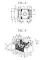
- an optical pickup actuator includes a base 10 having a support holder 11, a lens holder 20 having a lens mounting hole 21 formed therein, on which an objective lens 30 is mounted, a suspension or support member 13 connecting the lens holder 20 and the support holder 11, and a magnetic circuit driving the lens holder 20 in a focusing direction F, a tilting direction T, and a radial or tracking direction R independently of each other.
- the objective lens 30 is used for recording/reproducing information onto/from an optical disk with a predetermined recording density.
- the objective lens 30 may be designed to record/reproduce information onto/from a low-density optical disk, such as a DVD or a CD.
- the objective lens 30 may be designed to record/reproduce information onto/from a higher density optical disk than a DVD, i.e., an HD-DVD or a Blu-Ray disk.
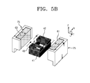
- the lens mounting hole 21 on which the objective lens 30 is mounted is provided at a central part of the lens holder 20. As shown in FIG. 4, a resting shoulder 21a is formed at a relatively deep position of the lens mounting hole 21 from an upper side of the lens holder 20 facing an optical disk (not shown).
- the upper side of the lens holder 20 is opened by the lens mounting hole 21, and a lower side of the lens holder 20 has a hex shaped opening through a coil mounting part 25.
- a focusing coil 41 and tilting coils 42, 43 are formed inside of the coil mounting part 25.
- the lens holder 20 may be made of injection molded plastic materials.
- the lens holder 20 is movably installed on the support holder 11 by the support member 13.
- the support member 13 may be formed of elastically transformable spring wires having a predetermined rigidity.
- a connection board 28 to which the support member 13 is connected is provided on an outer surface of the lens holder 20.
- the support member 13 may be soldered to the connection board 28.
- a current may be supplied to the magnetic circuit through the support member 13.
- the magnetic circuit drives the objective lens 30 independently in the focusing (F), tracking (R) and tilting (T) directions.
- the magnetic circuit includes a focusing coil 41, a pair of tilting coils 42, 43, two pairs of tracking coils 44, 45, and magnets.
- the magnets may include a pair of unipolar (axially magnetized) magnets 61, 63.
- the focusing coil 41 is wound around the objective lens 30 and about an axis parallel to the focusing direction (F).
- the focusing coil 41 may be wound on a rectangular coil form, and may be closely attached to an inner wall of the coil mounting part 25.
- the focusing coil may be layered to have a predetermined height in the focusing direction.
- the focusing coil 41 drives the lens holder 20 in the focusing direction by an interaction between sides of the focusing coil 41 parallel to the R direction and the axially magnetized magnets 61, 63.
- the focusing coil 41 moves upwardly or downwardly along the focusing direction according to a direction of current flow through the focusing coil 41, consequently moving the coil mounting part 25 and the objective lens 21 in the focusing direction.
- the tilting coils 42, 43 are spaced apart by a predetermined distance in the R direction. And, the tilting coils 42, 43 are arranged on opposite sides of the objective lens 30 to be symmetrical with each other in the R direction, are layered with the focusing coil 41 in the focusing direction, and are wound around respective axes extending in the focusing direction.
- tilting coils 42, 43 are disposed on the focusing coil 41, and are closely adhered to opposite inner walls of the coil mounting part 25.
- the tilting coils 42, 43 may have a smaller thickness in the focusing direction than the focusing coil 41.
- the force being applied in the focusing direction of the lens holder 20 is generated by the focusing coil 41.
- each tilting coil 42, 43 generates a force of an opposite direction with respect to the focusing direction. In this manner, the tilting coils 42, 43 are driven independent of the focusing coil 41, and move the lens holder 20 in the T direction using a relatively smaller force than the force generated by the focusing coil 41.
- a sidewall 20a of the lens holder 20 can be supported. Therefore, firmness of the sidewall 20a of the lens holder 20 is reinforced, enabling movement of a secondary resonance frequency at a high frequency and sufficient gain margin of the lens holder 20 in driving.
- the two pairs of tracking coils 44, 45 are provided on outer surfaces of the lens holder 20 in parallel relation with the R direction.
- the tracking coil pairs 44, 45 are effective coils whose parallel sides in the F direction are subject to a force in the R direction.
- the tracking coil pair 44 includes tracking coils 44a and 44b and the tracking coil pair 45 includes tracking coils 45a and 45b.
- the tracking coils 44a, 45a face each other having the lens holder 20 therebetween, receive co-directional electrical current and generate force in a same direction.
- the tracking coils 44b, 45b face each other i having the lens holder 20 therebetween, and generate a force in the same direction when receiving a current in an opposite direction as the tracking coils 44a, 45a.
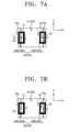
- operating sides C1, C2 of the tracking coils 44a, 44b, 45a, 45b, which neighbor with each other in the R direction are arranged to face the axially magnetized magnets 61, 63.
- the operating sides C3, C4, which are spaced from each other in the R direction, are arranged to face outer yokes 73, which will be described below.
- a force in the R direction is also generated at the operating sides C3, C4 due to the influence of flux coming out of the axially magnetized magnets 61, 63 and moving toward the neighboring outer yokes 73. That is, suppose that north polarity of each axially magnetized magnet 61, 63 faces the tracking coils 44, 45.
- the outer yokes 73 function as south polarity magnets. Therefore, the sides C1, C2, C3 and C4 of the tracking coils 44, 45 (FIG. 7A) parallel to the F direction can be used as effective coils, all receiving force in the R direction.
- the axially magnetized magnets 61, 63 are disposed on opposite sides of the lens holder 20, being parallel with the R direction.
- the axially magnetized magnets 61, 63 are arranged to have magnetic flux of opposite directions. In the embodiment shown with respect to FIGS. 2 and 3, north polarities of axially magnetized magnets 61, 63 face each other. Both axially magnetized magnets 61, 63 are involved with the independent movements of the lens holder 20 in the focusing, tilting and tracking directions, and the axially magnetized magnets 61, 63 are arranged for common use.
- the magnetic circuit includes three inner yoke pairs, i.e., first, second and third inner yoke pairs 71, 72 and 73, respectively, and a pair of outer yokes 75.
- the first inner yoke pair 71 is installed inside the tilting coil 42 and the focusing coil 41 on the base 10.
- the first inner yoke pair 71 may be arranged at the effective coil portion where the focusing coil 41 and the tilting coil 42 face the axially magnetized magnets 61, 63, namely, on opposite sides of an area parallel to the R direction.
- the first inner yoke pair 71 is made of a suitable material and may be made of a same metallic material as the base 10, thereby being one body together.
- the first inner yoke pair 71 while being separated from the focusing coil 41 and the tilting coil 42, guides the lines of magnetic flux generated from the focusing coil 41 and the tilting coil 42 in the F and R directions to maximize an intensity of an effective magnetic field.
- the second inner yoke pair 72 is spaced apart by a predetermined distance from the first inner yoke pair 71 in the R direction.
- the second inner yoke pair 72 is disposed inside of the focusing coil 41 and the tilting coil 43.
- the configuration and function of the second inner yoke pair 72 are similar to the configuration and function of the first inner yoke pair 71and a detailed description thereof will not be repeated.
- the third inner yoke pair 73 is disposed between the first inner yoke pair 71 and the second inner yoke pair 72.
- the third inner yoke pair 73 faces sides of the focusing coil 41 which are parallel to the R direction.
- the third inner yoke pair guides the lines of magnetic flux generated from the focusing coil 41 in the F direction to maximize the intensity of an effective magnetic field.
- the third inner yoke pair 73 may be made of a same material and shape as the first inner yoke pair 71.
- the base 10 may be separately formed or may be integrally formed with one, two or all of the first, second and third inner yoke pairs.
- the inner yoke pairs 71, 72, and 73 are installed by insertion through the opened bottom of the lens holder 20, that is a side opposite the lens hole 21, and the inner yoke pairs 71, 72 and 73 remain separated inside the lens holder 20.
- the outer yoke pair 75 is fixed at the base 10, and may be connected to the base 10 as one body.
- the outer yokes 75 are arranged on a surface of each of the axially magnetized magnets 61, 63 that faces away from the lens holder 20.
- One of the outer yoke pair 75 supports each axially magnetized magnet 61, 63, respectively.
- the outer yoke pair 75 guides the lines of magnetic flux generated from each axially magnetized magnet 61, 63, and focuses the magnetic flux to the lens holder 20, thereby maximizing the intensity of an effective magnetic field.
- a sectional shape of the outer yokes may be "U" shaped. That is, each yoke of the outer yoke pair 75 has a pair of extended parts 75a that extend in a direction perpendicular to the F direction to partially encompass opposite sides of a respective one of the axially magnetized magnets 61, 63. As shown in FIG. 7A, the extended parts 75a are installed, facing the sides C3, C4 which are separated from each other in the R direction of the tracking coils 44, 45.
- the sides C1, C2 adjacent to the tracking coils 44, 45 receive force generated from the interaction between the tracking coils 44, 45 and the axially magnetized magnets 61, 63, whereas the sides C3, C4 receive force in the R direction by a magnetic force applied to each extended part 75a.
- N north
- S south
- the optical pickup actuator according to the embodiment of the present invention shown in FIG. 3 will now be described.
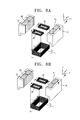
- the direction of a driving force generated by an interaction between the focusing coil 41 and the axially magnetized magnets 61, 63 is described.
- the focusing coil 41 is disposed between the axially magnetized magnets 61, 63.
- a current is applied to the focusing coil 41 in the counterclockwise direction.
- the positions of the object lens 30 on the lens holder 20 in the F direction is adjustable by controlling the polarity and amount of a current applied to the focusing coil 41.
- a current is applied to the focusing coil 41 to drive the lens holder 20 upwardly, similar to FIG. 5A.
- currents of opposite directions are applied to the tilting coils 42, 43.
- the tilting coils 42, 43 receive force of the opposite directions with respect to the axially magnetized magnets 61, 63, respectively. That is, the tilting coil 42 to which a current is applied in the clockwise direction receives a downwardly applied force with respect to the focusing direction.
- the tilting coil 43 to which a current is applied in the counterclockwise direction receives an upwardly applied force. Therefore, each tilting coil 42, 43 is driven independently of the focusing coil 41, thereby tilting the lens holder 20 in the T1 direction.
- the lens holder 20 can be driven downwardly in the focusing direction by applying a current to the focusing coil 41 in the same direction as shown in FIG. 5B.
- the tilting coil 42 receives an upwardly applied force
- the tilting coil 43 receives a downwardly applied force. Therefore, the lens holder 20 is driven downwardly by the focusing coil 41 and at the same time, the lens holder 20 is tilted in the T2 direction by the tilting coils 42, 43.
- the lens holder 20 in order to tilt the objective lens 30 mounted on the lens holder 20 in the tilting direction while moving the objective lens 30 in the focusing direction, it is necessary to apply a current to the focusing coil 41, and adjust the polarity and amount of a current that is applied to each of the tilting coils 42, 43 in an opposite direction from each other.
- the lens holder 20 can also be tilted by applying currents of opposite directions to the tilting coils 42, 43 only, without applying a current to the focusing coil 41.
- each tracking coil pair 44a, 44b, and 45a, 45b has long sides C1, C2, C3 and C4 in the F direction.
- the adjacent sides C1, C2 are arranged to face north polarities of the axially magnetized magnets 61, 63, whereas the other sides C3, C4 are arranged to face the extended parts 75a of the outer yoke pair 75 corresponding to south polarity.
- the object lens 30 mounted on the lens holder 20 may be driven in the R direction, according to the polarity and amount of a current applied to the tracking coils 44, 45.
- the focusing coil 41 and the tilting coils 42, 43 are independently installed and driven to control the lens holder 20 in the focusing and tilting directions. In this way, the adaptability of the objective lens to the system, and the sensitivity of the optical pickup may be improved.
- the rigidity of the injection molded lens holder may be reinforced by tightly attaching the focusing coil and the tilting coils to the inside of the lens holder. Hence, the sensitivity of the optical pickup can be increased even at a high speed, and the movement of a secondary resonant frequency at a high frequency is secured sufficiently.
- FIG. 8 is a schematic diagram showing an optical recording and/or reproducing apparatus to which the optical pickup actuator according to embodiments of the present invention may be applied.
- the optical recording and/or reproducing apparatus includes a spindle motor 110 rotating an optical medium such as an optical disk D, an optical pickup 120 movably installed in the radial direction of the optical medium D recording and/or reproducing information onto and/or from the optical medium D, a driving unit 130 driving the spindle motor 110 and the optical pickup 120, and a controller 140 controlling a focusing servo, a tracking servo and a tilting servo of the optical pickup 120.
- the optical medium D is chucked to a turntable 112 by a clamp 124.
- the optical pickup 120 includes an optical pickup system comprising an object lens 30 focusing a light emitted from a light source onto the optical medium, and an optical pickup actuator driving the object lens 30 about three axes.
- the optical pickup actuator described with respect to FIGS. 1-7B may be adopted to the optical recording/reproducing apparatus shown in FIG. 8.
- a reflected light from the optical medium D is detected through a photodetector provided to the optical pickup 120, and undergoes photoelectric transformation to become an electrical signal Vp.
- the electrical signal Vp is input to the controller 140 through the driving unit 130.
- the driving unit 130 controls rotation speed of the spindle motor 110, amplifies an input signal, and drives the optical pickup 120.
- the controller 140 sends a focusing servo command, a tracking servo command, and a tilting servo command, each being adjusted based on an input signal from the driving unit 130, to the driving unit 130 again to realize the focusing, tracking and tilting operations of the optical pickup 120.
- the embodiments of the present invention described herein disclose the actuator with one objective lens 30 for one lens holder 20, a number of objective lenses may be increased.
- two lens mounting holes may be formed in the lens holder 20, and an objective lens mounted on only one of the holes, or a plurality of objective lenses may be mounted on the two lens mounting holes.
- the magnetic circuit may be effectively used in this case as well, to adjust the position of the objective lens being used in a particular application.
- the actuator thereof can be applied to an optical pickup operating compatibly with a plurality of kinds of optical disks, such as, CD, DVD, and HD-DVD, for recording/reproducing information.
- the optical pickup actuator independently controls the objective ensor lenses in the focusing, tilting and tracking directions . Therefore, adaptability at a high speed is improved, and the sensitivity of the optical pickup can be improved. Moreover, the rigidity of the injection molded lens holder is reinforced by tightly attaching the focusing coil and the tilting coils to the inside of the lens holder. Hence, it becomes possible to secure the gain margin and the movement of a secondary resonant frequency (which is caused due to physical properties of the lens holder) at a high frequency. Overall, the optical pickup actuator of the present invention may be advantageously used for a high-speed optical recording/reproducing apparatus.
Landscapes
- Optical Recording Or Reproduction (AREA)
Applications Claiming Priority (1)
| Application Number | Priority Date | Filing Date | Title |
|---|---|---|---|
| KR1020050031093A KR100689035B1 (ko) | 2005-04-14 | 2005-04-14 | 광픽업용 액츄에이터 및 광기록 및/또는 재생장치 |
Publications (2)
| Publication Number | Publication Date |
|---|---|
| EP1729295A2 true EP1729295A2 (de) | 2006-12-06 |
| EP1729295A3 EP1729295A3 (de) | 2006-12-20 |
Family
ID=36686077
Family Applications (1)
| Application Number | Title | Priority Date | Filing Date |
|---|---|---|---|
| EP06111632A Ceased EP1729295A3 (de) | 2005-04-14 | 2006-03-23 | Stellantrieb für einen optischen Lesekopf und optische Aufzeichnungs- und/oder Wiedergabevorrichtung damit |
Country Status (4)
| Country | Link |
|---|---|
| US (1) | US7969828B2 (de) |
| EP (1) | EP1729295A3 (de) |
| KR (1) | KR100689035B1 (de) |
| CN (1) | CN100419877C (de) |
Families Citing this family (5)
| Publication number | Priority date | Publication date | Assignee | Title |
|---|---|---|---|---|
| KR100689035B1 (ko) * | 2005-04-14 | 2007-03-08 | 삼성전자주식회사 | 광픽업용 액츄에이터 및 광기록 및/또는 재생장치 |
| KR100689042B1 (ko) * | 2005-04-20 | 2007-03-09 | 삼성전자주식회사 | 광픽업용 액츄에이터 및 광기록 및/또는 재생장치 |
| TWI336073B (en) * | 2006-12-27 | 2011-01-11 | Ind Tech Res Inst | Optical pick-up head and electro-magnetic actuator thereof |
| JP5261115B2 (ja) * | 2008-02-29 | 2013-08-14 | 三洋電機株式会社 | ピックアップ装置 |
| US10382698B2 (en) * | 2015-09-30 | 2019-08-13 | Apple Inc. | Mobile zoom using multiple optical image stabilization cameras |
Family Cites Families (25)
| Publication number | Priority date | Publication date | Assignee | Title |
|---|---|---|---|---|
| KR100518873B1 (ko) * | 2000-11-04 | 2005-09-30 | 엘지전자 주식회사 | 광 픽업 액츄에이터 |
| JP2002342952A (ja) * | 2001-05-15 | 2002-11-29 | Pioneer Electronic Corp | 光学式記録再生装置 |
| KR100421041B1 (ko) * | 2001-06-19 | 2004-03-04 | 삼성전자주식회사 | 광픽업 액튜에이터, 광픽업 장치 및 광기록/재생 장치 |
| JP2003173557A (ja) | 2001-12-05 | 2003-06-20 | Sanyo Electric Co Ltd | 光ピックアップ装置 |
| JP2003173556A (ja) * | 2001-12-07 | 2003-06-20 | Tdk Corp | 光ヘッド装置 |
| KR20040013327A (ko) | 2002-08-05 | 2004-02-14 | 엘지전자 주식회사 | 광픽업 액츄에이터 |
| JP2004110891A (ja) | 2002-09-13 | 2004-04-08 | Sanyo Electric Co Ltd | 光ピックアップ装置 |
| KR100505644B1 (ko) | 2002-10-16 | 2005-08-03 | 삼성전자주식회사 | 광픽업 액츄에이터 및 이를 채용한 데이터 기록/재생 장치 |
| KR100522594B1 (ko) * | 2002-10-25 | 2005-10-24 | 삼성전자주식회사 | 호환형 광픽업장치 및 이를 채용한 광기록재생장치 |
| JP2004185654A (ja) | 2002-11-29 | 2004-07-02 | Sumida Technologies Inc | 光ピックアップ |
| JP2004213861A (ja) * | 2002-12-20 | 2004-07-29 | Sharp Corp | 対物レンズ駆動装置及び光ピックアップ装置。 |
| JP3828081B2 (ja) * | 2003-01-16 | 2006-09-27 | スミダコーポレーション株式会社 | 光ピックアップ |
| KR100510545B1 (ko) | 2003-01-29 | 2005-08-26 | 삼성전자주식회사 | 틸트 구동가능한 광픽업 액츄에이터 및 이를 채용한 광기록 및/또는 재생기기 |
| US20040268373A1 (en) * | 2003-01-29 | 2004-12-30 | Samsung Electronics Co., Ltd. | Tilt drive optical pickup actuator and optical recording and/or reproducing apparatus using the same and method |
| KR100505673B1 (ko) * | 2003-02-21 | 2005-08-03 | 삼성전자주식회사 | 틸트 구동 광픽업 액츄에이터 및 이를 채용한 광 기록및/또는 재생기기 |
| JP3821105B2 (ja) | 2003-02-28 | 2006-09-13 | 三菱電機株式会社 | 光学手段駆動装置 |
| JP2004326914A (ja) * | 2003-04-24 | 2004-11-18 | Sankyo Seiki Mfg Co Ltd | 光ヘッド装置 |
| KR100505687B1 (ko) * | 2003-06-02 | 2005-08-03 | 삼성전자주식회사 | 광픽업 액츄에이터 및 이를 채용한 광디스크 드라이브 |
| JP3855977B2 (ja) | 2003-07-16 | 2006-12-13 | ソニー株式会社 | 光ピックアップ及びディスクドライブ装置 |
| JP2005038537A (ja) * | 2003-07-17 | 2005-02-10 | Mitsumi Electric Co Ltd | 対物レンズ駆動装置 |
| JP4146313B2 (ja) * | 2003-08-20 | 2008-09-10 | 日本電産サンキョー株式会社 | 光ヘッド装置 |
| KR100710756B1 (ko) * | 2004-12-22 | 2007-04-24 | 삼성전자주식회사 | 광픽업용 액츄에이터 및 광기록 및/또는 재생장치 |
| KR100689035B1 (ko) * | 2005-04-14 | 2007-03-08 | 삼성전자주식회사 | 광픽업용 액츄에이터 및 광기록 및/또는 재생장치 |
| KR100689042B1 (ko) * | 2005-04-20 | 2007-03-09 | 삼성전자주식회사 | 광픽업용 액츄에이터 및 광기록 및/또는 재생장치 |
| KR200413327Y1 (ko) | 2006-01-24 | 2006-04-07 | 김대운 | 이온수기 |
-
2005
- 2005-04-14 KR KR1020050031093A patent/KR100689035B1/ko not_active Expired - Fee Related
-
2006
- 2006-03-23 EP EP06111632A patent/EP1729295A3/de not_active Ceased
- 2006-04-13 US US11/402,990 patent/US7969828B2/en not_active Expired - Fee Related
- 2006-04-14 CN CNB2006100743885A patent/CN100419877C/zh not_active Expired - Fee Related
Non-Patent Citations (1)
| Title |
|---|
| None |
Also Published As
| Publication number | Publication date |
|---|---|
| US20060233067A1 (en) | 2006-10-19 |
| KR20060108876A (ko) | 2006-10-18 |
| KR100689035B1 (ko) | 2007-03-08 |
| CN1848256A (zh) | 2006-10-18 |
| US7969828B2 (en) | 2011-06-28 |
| CN100419877C (zh) | 2008-09-17 |
| EP1729295A3 (de) | 2006-12-20 |
Similar Documents
| Publication | Publication Date | Title |
|---|---|---|
| KR100636127B1 (ko) | 광픽업용 액츄에이터 | |
| JPH10334493A (ja) | 光ピックアップアクチュエータ | |
| US7969828B2 (en) | Optical pickup actuator and optical recording and/or reproducing apparatus having the same | |
| US20040148620A1 (en) | Magnetic circuit, and optical pickup actuator and optical recording and/or reproducing apparatus using the magnetic circuit | |
| EP1717800B1 (de) | Stellantrieb für optischen Lesekopf und optische Aufzeichnungs- und/oder Wiedergabevorrichtung | |
| US7668049B2 (en) | Optical pickup actuator and optical recording/reproducing apparatus | |
| CN100489973C (zh) | 光学拾取装置 | |
| US7643386B2 (en) | Optical pickup actuator and optical recording and/or reproducing apparatus | |
| US5724324A (en) | Optical pickup actuator with an objective lens fixing part suspended by an elastic members | |
| EP1600960B1 (de) | Optisches Abtastgerät und Verfahren, und Wiedergabe- und/oder Aufzeichnungsgerät damit | |
| US7453656B2 (en) | Recording and/or reproducing apparatus with an optical pickup actuator having high thrust | |
| EP2141701B1 (de) | Optische Lesekopfvorrichtung mit zwei Stellantrieben | |
| US20050259527A1 (en) | Optical component triaxial actuator and recording/reproducing apparatus using the same | |
| KR100329999B1 (ko) | 광픽업의 대물렌즈 구동장치 | |
| EP1724768A2 (de) | Stellantrieb für einen optischen Lesekopf und optische Aufzeichnungs- und/oder Wiedergabevorrichtung damit | |
| CN101123099A (zh) | 光拾取器 | |
| KR20020028628A (ko) | 광픽업의 대물렌즈 구동장치 | |
| KR20050106855A (ko) | 광 픽업장치에서의 광 검출기용 액츄에이터 |
Legal Events
| Date | Code | Title | Description |
|---|---|---|---|
| PUAI | Public reference made under article 153(3) epc to a published international application that has entered the european phase |
Free format text: ORIGINAL CODE: 0009012 |
|
| PUAL | Search report despatched |
Free format text: ORIGINAL CODE: 0009013 |
|
| AK | Designated contracting states |
Kind code of ref document: A2 Designated state(s): AT BE BG CH CY CZ DE DK EE ES FI FR GB GR HU IE IS IT LI LT LU LV MC NL PL PT RO SE SI SK TR |
|
| AX | Request for extension of the european patent |
Extension state: AL BA HR MK YU |
|
| AK | Designated contracting states |
Kind code of ref document: A3 Designated state(s): AT BE BG CH CY CZ DE DK EE ES FI FR GB GR HU IE IS IT LI LT LU LV MC NL PL PT RO SE SI SK TR |
|
| AX | Request for extension of the european patent |
Extension state: AL BA HR MK YU |
|
| 17P | Request for examination filed |
Effective date: 20070314 |
|
| 17Q | First examination report despatched |
Effective date: 20070423 |
|
| AKX | Designation fees paid |
Designated state(s): DE GB NL |
|
| STAA | Information on the status of an ep patent application or granted ep patent |
Free format text: STATUS: THE APPLICATION HAS BEEN REFUSED |
|
| 18R | Application refused |
Effective date: 20120131 |