EP1717800B1 - Stellantrieb für optischen Lesekopf und optische Aufzeichnungs- und/oder Wiedergabevorrichtung - Google Patents
Stellantrieb für optischen Lesekopf und optische Aufzeichnungs- und/oder Wiedergabevorrichtung Download PDFInfo
- Publication number
- EP1717800B1 EP1717800B1 EP06112778A EP06112778A EP1717800B1 EP 1717800 B1 EP1717800 B1 EP 1717800B1 EP 06112778 A EP06112778 A EP 06112778A EP 06112778 A EP06112778 A EP 06112778A EP 1717800 B1 EP1717800 B1 EP 1717800B1
- Authority
- EP
- European Patent Office
- Prior art keywords
- focusing
- tracking
- coils
- optical pickup
- coil
- Prior art date
- Legal status (The legal status is an assumption and is not a legal conclusion. Google has not performed a legal analysis and makes no representation as to the accuracy of the status listed.)
- Expired - Fee Related
Links
Images


Classifications
-
- G—PHYSICS
- G11—INFORMATION STORAGE
- G11B—INFORMATION STORAGE BASED ON RELATIVE MOVEMENT BETWEEN RECORD CARRIER AND TRANSDUCER
- G11B7/00—Recording or reproducing by optical means, e.g. recording using a thermal beam of optical radiation by modifying optical properties or the physical structure, reproducing using an optical beam at lower power by sensing optical properties; Record carriers therefor
- G11B7/08—Disposition or mounting of heads or light sources relatively to record carriers
- G11B7/09—Disposition or mounting of heads or light sources relatively to record carriers with provision for moving the light beam or focus plane for the purpose of maintaining alignment of the light beam relative to the record carrier during transducing operation, e.g. to compensate for surface irregularities of the latter or for track following
- G11B7/095—Disposition or mounting of heads or light sources relatively to record carriers with provision for moving the light beam or focus plane for the purpose of maintaining alignment of the light beam relative to the record carrier during transducing operation, e.g. to compensate for surface irregularities of the latter or for track following specially adapted for discs, e.g. for compensation of eccentricity or wobble
- G11B7/0956—Disposition or mounting of heads or light sources relatively to record carriers with provision for moving the light beam or focus plane for the purpose of maintaining alignment of the light beam relative to the record carrier during transducing operation, e.g. to compensate for surface irregularities of the latter or for track following specially adapted for discs, e.g. for compensation of eccentricity or wobble to compensate for tilt, skew, warp or inclination of the disc, i.e. maintain the optical axis at right angles to the disc
-
- G—PHYSICS
- G11—INFORMATION STORAGE
- G11B—INFORMATION STORAGE BASED ON RELATIVE MOVEMENT BETWEEN RECORD CARRIER AND TRANSDUCER
- G11B7/00—Recording or reproducing by optical means, e.g. recording using a thermal beam of optical radiation by modifying optical properties or the physical structure, reproducing using an optical beam at lower power by sensing optical properties; Record carriers therefor
- G11B7/08—Disposition or mounting of heads or light sources relatively to record carriers
- G11B7/085—Disposition or mounting of heads or light sources relatively to record carriers with provision for moving the light beam into, or out of, its operative position or across tracks, otherwise than during the transducing operation, e.g. for adjustment or preliminary positioning or track change or selection
-
- G—PHYSICS
- G11—INFORMATION STORAGE
- G11B—INFORMATION STORAGE BASED ON RELATIVE MOVEMENT BETWEEN RECORD CARRIER AND TRANSDUCER
- G11B7/00—Recording or reproducing by optical means, e.g. recording using a thermal beam of optical radiation by modifying optical properties or the physical structure, reproducing using an optical beam at lower power by sensing optical properties; Record carriers therefor
- G11B7/08—Disposition or mounting of heads or light sources relatively to record carriers
- G11B7/09—Disposition or mounting of heads or light sources relatively to record carriers with provision for moving the light beam or focus plane for the purpose of maintaining alignment of the light beam relative to the record carrier during transducing operation, e.g. to compensate for surface irregularities of the latter or for track following
- G11B7/0925—Electromechanical actuators for lens positioning
- G11B7/093—Electromechanical actuators for lens positioning for focusing and tracking
-
- G—PHYSICS
- G11—INFORMATION STORAGE
- G11B—INFORMATION STORAGE BASED ON RELATIVE MOVEMENT BETWEEN RECORD CARRIER AND TRANSDUCER
- G11B7/00—Recording or reproducing by optical means, e.g. recording using a thermal beam of optical radiation by modifying optical properties or the physical structure, reproducing using an optical beam at lower power by sensing optical properties; Record carriers therefor
- G11B7/08—Disposition or mounting of heads or light sources relatively to record carriers
- G11B7/09—Disposition or mounting of heads or light sources relatively to record carriers with provision for moving the light beam or focus plane for the purpose of maintaining alignment of the light beam relative to the record carrier during transducing operation, e.g. to compensate for surface irregularities of the latter or for track following
- G11B7/0925—Electromechanical actuators for lens positioning
- G11B7/0933—Details of stationary parts
-
- G—PHYSICS
- G11—INFORMATION STORAGE
- G11B—INFORMATION STORAGE BASED ON RELATIVE MOVEMENT BETWEEN RECORD CARRIER AND TRANSDUCER
- G11B7/00—Recording or reproducing by optical means, e.g. recording using a thermal beam of optical radiation by modifying optical properties or the physical structure, reproducing using an optical beam at lower power by sensing optical properties; Record carriers therefor
- G11B7/08—Disposition or mounting of heads or light sources relatively to record carriers
- G11B7/09—Disposition or mounting of heads or light sources relatively to record carriers with provision for moving the light beam or focus plane for the purpose of maintaining alignment of the light beam relative to the record carrier during transducing operation, e.g. to compensate for surface irregularities of the latter or for track following
- G11B7/0925—Electromechanical actuators for lens positioning
- G11B7/0935—Details of the moving parts
Definitions
- An aspect of the present invention relates in general to an optical pickup actuator and an optical recording and/or reproducing apparatus, and, more specifically, to an optical pickup actuator which drives an objective lens to record and/or reproduce information onto and/or from an optical information storage medium, and an optical recording and/or reproducing apparatus having the same installed therein.
- An optical recording and/or reproducing apparatus is provided with an optical pickup to record optical information by irradiating a laser beam onto an optical recording medium, such as a compact disk (CD), a digital versatile disk (DVD), etc., and reproducing the recorded optical information from the optical recording medium.
- an optical recording medium such as a compact disk (CD), a digital versatile disk (DVD), etc.
- the optical pickup requires an objective lens, which focuses an incident light to the optical recording medium, and an actuator, which drives the objective lens in a focusing direction and a tracking direction.
- the actuator includes a base, a lens holder on which an objective lens is mounted, and a magnetic circuit to drive the lens holder in a focusing direction and a tracking direction, while supporting the lens holder to move with respect to the base.
- the magnetic circuit comprising focusing coils driving an objective lens in a focusing direction, tracking coils driving an objective lens in a tracking direction, and magnets installed, facing the coils to interact with the coils.
- the actuator drives the focusing coils and the tracking coils independently to control the movement of the objective lens in the focusing direction and the tracking direction.
- the optical recording medium does not rotate horizontally, but, rather, may be deformed up and down.
- US2003/0039185 discloses an apparatus and method for driving circuit elements.
- an aspect of the present invention to provide an optical pickup actuator with a sample structure and high sensitivity, and an optical recording and/or reproducing apparatus having the same installed therein.
- an optical pickup actuator including: a lens holder movably installed on a base by a support member, and mounted with an objective lens adapted to transmit an incident light to an optical information recording medium; and a magnetic circuit operable to independently drive the lens holder in a focusing direction, a tilting direction and a tracking direction, respectively.
- the magnetic circuit includes: a first and a second focusing coil installed on the lens holder in the tracking direction; a tilting coil installed on the lens holder, the tilting coil being layered with the first and second focusing coils in the focusing direction; a pair of tracking coils installed on the lens holder, and being arranged in parallel to the tracking direction; and magnets adapted to interact with the focusing coils, the tilting coil and the tracking coils to generate a driving force in a focusing direction, a tilting direction and a tracking direction, respectively.
- the magnets comprise: a pair of first magnet parts arranged on a first side of the lens holder, in which magnet polarities of each of the first magnet parts are opposite each other; and a pair of second magnet parts (61b,63b) arranged on a second side of the lens holder, opposite the first side, each second magnet part (61b,63b) being in parallel with a corresponding first magnet part, in which magnet polarities of each of the second magnet parts are opposite each other in a reverse arrangement compared with the first magnet parts.
- the first and second magnet parts are installed on the first and second sides of the lens holder to correspond with each other, and each comprise a pair of bipolar magnets that are bipolarized in a parallel direction with operating sides of the focusing coils.
- a pair of the first and second focusing coils are spaced apart by a predetermined distance from each other in the tracking direction, and the first and second focusing coils and the tilting coils are layered in the focusing direction.
- the focusing coils are disposed on the tilting coil with respect to the focusing direction.
- the focusing coils and the tilting coil are tightly attached to the inner wall of the lens holder.
- the magnetic circuit further includes: inner yokes installed on the insides of the focusing coils and the tilting coil; and outer yokes installed on the outside of the focusing coils and the tilting coil.
- the outer yokes are installed on the base and support the magnet parts, respectively.
- the inner yokes comprise: a first inner yoke pair installed proximate to sides of the first focusing coil and the tilting coil in parallel with each other in the tracking direction; a second inner yoke pair installed proximate to sides of the second focusing coil and the tilting coil in parallel with each other in the tracking direction; and a third inner yoke pair disposed between the first and the second inner yoke pair.
- the third inner yoke pair is disposed between the first and the second focusing coil.
- the first, second, and third inner yoke pairs are combined with the base as one body.
- the tracking coil pair is installed on an outer side of the lens holder facing the magnet part, and is disposed between the focusing coils in the tracking direction.
- the tracking coils are arranged in such a pattern that among the sides of the tracking coils facing the magnets, the sides in parallel to the focusing direction contribute to the generation of an electromagnetic force in the tracking direction.
- an optical pickup actuator including: a lens holder capable of mounting an objective lens to record and/or reproduce information onto and/or from an optical information storage medium; a support member adapted to support the lens holder to be movable with respect to a base; and a magnetic circuit operable to independently drive the lens holder in a focusing direction, a tilting direction and a tracking direction, respectively.
- the magnetic circuit preferably includes: a plurality of focusing coils installed on the lens holder, the plurality of the focusing coils being arranged on the lens holder to be symmetric about the tracking direction and wound with respect to the focusing direction; a tilting coil installed on the lens holder, being wound around the objective lens; a pair of tracking coils installed on the lens holder, the pair of tracking coils being arranged in parallel with each other in the tracking direction and being wound around a profile of the objective lens; and a pair of polar magnets installed on both sides of the lens holder, each polar magnet being bipolarized in the tracking direction.
- the focusing coils are layered with the tilting coil in the focusing direction.
- each of the bipolar magnet pair is disposed on opposite sides of the focusing coils so as to oppose each other each other.
- the tracking coils are installed on an outer side of the lens holder, facing the bipolar magnets, respectively.
- each of the tracking coils is disposed between the focusing coils in the tracking direction.
- the tracking coils are installed in such a manner that operating sides thereof are disposed on both sides of a polarity boundary of the bipolar magnet.
- the magnetic circuit includes: outer yokes installed on the base for supporting each of the bipolar magnets; and a plurality of inner yokes installed inside of the focusing coils on the base.
- the inner yokes comprise three inner yoke pairs arranged in parallel to the tracking direction.
- Still another aspect of the present invention provides an optical recording and/or reproducing apparatus, comprising: an optical pickup having an objective lens and an actuator operable to drive the objective lens, the optical pickup being movably installed in a radial direction of an optical information storage medium for recording and/or reproducing information onto and/or from the optical information storage medium; and a controller operable to control a focusing servo, a tracking servo, and a tilting servo.
- the actuator comprises: a lens holder movably installed on a base by a support member to mount an objective lens; and a magnetic circuit to independently drive the lens holder in a focusing direction, a tilting direction and a tracking direction, respectively.
- the magnetic circuit comprises: a pair of focusing coils installed on the lens holder and being spaced apart by a predetermined distance in the tracking direction; a tilting coil installed in parallel to the focusing coils in the focusing direction; a pair of polar magnets installed on both sides of the lens holder, and being bipolarized along the arrangement direction of the focusing coils; and a pair of tracking coil pairs installed between the polar magnets and the lens holder.
- each of the polar magnet pair is respectively disposed on both sides of the lens holder to have a magnetic flux of opposite direction in the diagonal direction.
- an optical pickup actuator includes a support holder 11 installed on a base 10, a lens holder 20 having a lens mounting hole 21 formed therein, on which an objective lens 30 is mounted, a support member (a suspension 13) connecting the lens holder 20 and the support holder 11, and a magnetic circuit independently driving the lens holder 20 in a focusing direction, a tilting direction and a tracking direction, respectively.
- the objective lens 30 is used to record and/or reproduce information onto/from an optical disk with a predetermined recording density.
- the objective lens 30 may be designed to record/reproduce information onto/from a low-density optical disk, such as a DVD disk as well as a CD disk.
- the objective lens 30 may be designed to record/reproduce information onto/from a higher density optical disk than a DVD, i.e., HD-DVD optical disk.
- the lens mounting hole 21, on which the objective lens 30 is mounted, is located on the central part of the lens holder 20.
- a resting jaw 21a is formed at a predetermined depth from the upper side of the lens holder 2 so as to support the objective lens 30 to a predetermined height with respect to the upper side of the lens holder 20.
- the upper side of the lens holder 20 is opened by the lens mounting hole 21, and the entire lower side thereof is opened.
- a space inside of the lens holder 20 is empty, and focusing coils 41, 42 (to be described below) and at least one tilting coil 43 are closely attached to the inner side of the lens holder 20.
- the lens holder 20 is movably installed on the support holder 11 by the support member 13.
- the support member 13 is formed of elastically transformable spring wires having a predetermined rigidity.
- a connection board 28, to which the support member 13 is connected, is provided outside of the lens holder 20.
- the support member 13 is soldered to the connection board 28.
- a current may be supplied to the magnetic circuit through the support member 13.
- the lens holder 20 is made of injection molded plastic materials.
- the magnetic circuit is used to drive the objective lens 30 independently in the focusing (F), tracking (R) and tilting (T) directions.
- the magnetic circuit comprises a first and a second focusing coil 41, 42, a tilting coil 43, a first and a second tracking coil 44, 45, and a first and a second polar (or, more particularly, bipolar) magnet 61, 63.
- the first and second focusing coils 41, 42 are spaced apart from each other by a predetermined distance in the R direction of FIG. 3 . As shown in FIG. 4 , the focusing coils 41, 42 are disposed close to the inner wall of the lens holder 20.
- the focusing coils 41, 42 are rectangularly wound to extend up to a predetermined height in the focusing direction (the F direction of FIG. 3 ).
- each focusing coil 41 and 42 is symmetrically disposed on either side of the objective lens 30.
- the focusing coils 41, 42 receive a force to drive the lens holder 20 in the focusing direction F, of FIG. 3 as a result of the interaction between the sides of the focusing coils 41, 42 that are parallel to the R direction and the first and second polar magnets 61, 63.
- the first and second focusing coils 41, 42 are installed in such a pattern such that when currents are applied thereto, to run in opposite directions, the focusing coils 41, 42 receive forces acting in similar directions.
- the tilting coil 43 is layered with the focusing coils 41, 42 in the F direction of FIG. 3 .
- the tilting coil 43 is rectangularly wound and close to the inner wall of the lens holder 20.
- the tilting coil 43 is layered under the focusing coils 41, 42 in the F direction.
- the tilting coil 43 could be layered above the focusing coils 41, 42.
- the tilting coil 43 allows for the lens holder 20 to be driven to rotate about an axis that is parallel with the T direction of FIG. 3 by generating a force that acts in a rotational direction extending around the objective lens 30 mounted on the lens holder 20.
- a current having the same direction with the current applied to one of the focusing coils 41, 42 is applied to the tilting coil 43, and the tilting coil 43 receives force in the T direction.
- the tilting coil 43 being driven independently of the focusing coils 41, 42, then drives the lens holder 20 to tilt.
- the first and second tracking coils 44, 45 are installed along a center line, extending in the T direction of FIG. 3 , of the lens holder 20in parallel with each other.
- the tracking coils 44, 45 are spaced and disposed such that the center line along which the tracking coils 44, 45 are disposed is located between the focusing coils 41, 42 in the R direction of FIG. 3 .
- each tracking coil 44 and 45 is disposed proximate to the north polarity part and the south polarity part of each polar magnet 61, 63, respectively.
- each tracking coil 44, 45 is rectangularly wound, sides of the tracking coils 44, 45 that are parallel to the F direction face towards north polarity parts 61a, 63a and south polarity parts 61b, 63b of the polar magnets 61, 63. Meanwhile, vertical sides of the tracking coils 44, 45 receive force from the interaction between the tracking coils 44, 45 with the polar magnets 61, 63 to drive the lens holder 20 in the R direction of FIG. 3 .
- the first and second polar magnets 61, 63 are disposed along the lens holder 20, and are spaced apart by a predetermined longitudinal distance, with each polar magnet being rectangular with a long side extending in parallel to the R direction of the lens holder 20.
- Each of the polar magnets 61, 63 has a first part 61a, 63a, and a second part 61b, 63b, which are polarized in the R direction of FIG. 3 .
- Both polar magnets 61, 63 are involved with driving the lens holder 20 in the F, T and R directions, and are arranged for common use in accordance with the operation of the focusing coils 41, 42, the tilting coil 43, and the tracking coils 44, 45.
- the first part 61a of the first polar magnet 61 has a similar polarity as the second part 63b of the second magnet 63 and vice versa.
- the first part 61a of the first polar magnet 61 and the first part 63a of the second polar magnet 63 are disposed similarly on either side of the first focusing coil 41. That is, the first parts 61a, 63a are arranged with opposing polarities so as to cause a magnetic flux to reach in opposite directions.
- the first parts 61a, 63a of the first and second magnets 61, 63 are arranged such that north polarities face each other.
- the second parts 61b, 63b of the first and second magnets 61, 63 are arranged such that south polarities face each other.
- the polarities of the magnets described above could be reversed.
- first magnet M1 the first parts 61a, 63a of the first and second polar magnets 61, 63
- second magnet M2 the second parts 61b, 63b of the first and second polar magnets 61, 63 will be hereinafter referred to as a "second magnet M2”.
- the first magnet M1 generates an electromagnetic force by interacting with the first focusing coil 41, and allows the sides of the first focusing coil 41 that are parallel to the R direction of FIG. 3 to drive the lens holder 20 in the F direction.
- second magnet M2 generates an electromagnetic force by interacting with the second focusing coil 42, and allows the sides of the second focusing coil 42 parallel to the R direction of FIG.
- the focusing coils 41, 42 receive force in a similar direction when currents of opposite directions are applied to the focusing coils 41, 42, respectively.
- the first magnet M1 and the second magnet M2 interact with the tilting coil 43, and generate an electromagnetic force so as to drive the lens holder 20 in the T direction of FIG. 3 .
- the first and the second magnet M1, M2 have opposing magnet polarities, because the position of the tilting coil 43 is spread across the lens holder in the R direction of FIG. 3 such that the tilting coil 43 is proximate to both magnets M1, M2, a current, applied to the tilting coil 43 in one direction causes the tilting coil 43 to receive forces of opposite directions at opposing positions along the length of the tilting coil 43.
- the lens holder is made to tilt about an axis extending in the T direction.
- first and second magnets M1, M2 interact with the tracking coils 44, 45 to generate an electromagnetic force, which drives the lens holder 20 in the R direction. More details on this operation are provided below.
- the magnetic circuit comprises three inner yoke pairs, i.e., first to third inner yoke pairs 71, 72, and 73.
- the first inner yoke pair 71 is installed on the lens holder 20 and surrounded by the first focusing coil 41.
- the first inner yoke pair 71 is arranged at the effective coil portion where the first focusing coil 41 and the tilting coil 43 face the first magnet M1 and are parallel with each other in the R direction of FIG. 3 .
- the first inner yoke pair 71 may be made of a metallic material similar to that of the base 10 such that the first inner yoke pair 71 may be integrally connected to the base 10.
- the first inner yoke pair 71 while being separated from the first focusing coil 41 and the tilting coil 43, guides the lines of magnetic force generated from the first focusing coil 41 and the tilting coil 43 in the F and T directions to maximize the intensity of an effective magnetic field.
- the second inner yoke pair 72 is spaced apart, by a predetermined distance, from the first inner yoke pair 71 in the R direction and is disposed on the lens holder 20 and surrounded by the second focusing coil 42 in a similar way as the first inner yoke pair 71. Indeed, as with the first inner yoke pair 71, the second inner yoke pair 72 is arranged at the effective coil portion where the second focusing coil 42 and the tilting coil 43 face the second magnet M2 and are parallel with each other in the R direction of FIG. 3 .
- the second inner yoke pair 72 a metallic material that is similar to that of the base 10 to facilitate their being integrally connected.
- the second inner yoke pair 72 guides the lines of magnetic force generated from the second focusing coil 42 and the tilting coil 43 in the F and T directions to maximize the intensity of an effective magnetic field.
- the third inner yoke pair 73 is disposed between the first inner yoke pair 71 and the second inner yoke pair 72. In an embodiment of the invention, the third inner yoke pair 73 may be integrally combined with the base 10.
- the third inner yoke pair 73 is arranged inside the tilting coil 43 to face an effective coil part parallel to the R direction.
- the third inner yoke pair 73 is installed in opposition to the tracking coils 44, 45.
- the third inner yoke pair 73 guides the lines of magnetic force generated from the tracking coils 44, 45 in the R direction to maximize the intensity of an effective magnetic field.
- the outer yoke pair 75 is, in an embodiment of the invention, fixed at the base 10, or may be made of a metallic material that is similar to that of the base 10 and may be integrally connected to the base 10.
- the outer yokes are arranged on the plane that does not face the lens holder 20 of each of the polar magnets 61, 63.
- the outer yoke pair 75 support each polar magnet 61, 63.
- the outer yoke pair 75 guides the lines of magnetic force generated from each polar magnet 61, 63, and focuses them to the lens holder 20 to maximize the intensity of an effective magnetic field.
- the direction of a driving force generated by an interaction between the first and second focusing coil 41, 42 and the first and second magnets M1, M2 is described.
- the focusing coils 41, 42 are disposed between the polar magnets 61, 63.
- the first focusing coil 41 is driven by an interaction with the first magnet M1
- the second focusing coil 42 is driven by an interaction with the second magnet M2.
- currents of opposite directions are applied to the focusing coils 41, 42. Since a north polarity of each of the first parts 61a, 63a in the first magnet M1 each faces inwardly with respect to the lens holder 20, magnetic fields generated by the first magnet M1 are repelled in opposite directions.
- a current is applied to the first focusing coil 41 in the counterclockwise direction, the sides of the first focusing coil 41 that are parallel to the R direction are subjected to an upward force, according to Fleming's left hand rule.
- the focusing direction of the objective lens 30 mounted on the lens holder 20 may be adjusted by controlling the polarity and amount of a current applied to each focusing coil 41, 42.
- a current is applied to each focusing coil 41, 42 to drive the lens holder 20 upwardly, similar to FIG. 5A .
- a current is applied to the tilting coil 43 in the counterclockwise direction. Then, the tilting coil 43 receives an upwardly applied force in a portion corresponding to the first magnet M1, whereas a downwardly applied force in a portion corresponding to the second magnet M2. This allows the tilting coil 43 to tilt the lens holder 20 to either side, independently from the focusing coils 41, 42. That is, in the case illustrated by FIG.
- a bobbin 20 moves upwardly by the focusing coils 41, 42, and, at the same time, may be tilted by the tilting coil 43 in the T1 direction by a predetermined angle.
- the tilt angle in the T1 direction may be controlled by adjusting the amount of current applied to the tilting coil 43 and the focusing coils 41, 42, respectively.
- the lens holder 20 may be focused downwardly by applying currents to the first and second focusing coils 41, 42 in the same direction shown in FIG. 5B .
- a current may be additionally applied to the tilting coil 43 in the clockwise direction.
- the tilting coil 43 receives an upwardly applied force in a portion corresponding to the first magnet M1 and a downwardly applied force in a portion corresponding to the second magnet M2.
- the lens holder 20 is driven downwardly by the first and second focusing coils 41, 42 and at the same time, is tilted by the focusing coils 41, 42 in the T2 direction by a predetermined angle.
- the lens holder 20 may also be tilted by applying a current only to the tilting coil 43, without applying currents to the focusing coils 41, 42.
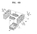
- the polar magnet 61 facing the tracking coil 44 is bipolarized to N and S poles.
- the tracking coil 44 has longitudinally elongated sides, and these elongated sides correspond to the first part 61a of N pole and the second part 61b of S pole, respectively.
- each of the elongated sides of the tracking coil 44 is understood to become an effective tracking coil contributing to the generation of an electromagnetic force when a current is applied thereto in the counterclockwise direction.
- the elongated sides receive a force in the left direction on the drawing.
- the focusing coils 41, 42 and the tilting coil 43 are installed and driven independently from each other.
- the adaptibility of the objective lens 30 to the system, and the sensitivity of the optical pickup may be improved.
- the rigidity of the injection molded lens holder may be reinforced by tightly attaching the focusing coils 41, 42 and the tilting coil 43 to the inside of the lens holder 20.
- the sensitivity of the optical pickup may be increased even at a high speed, and the movement of a secondary resonant frequency at a high frequency is sufficiently secured.
- FIG. 8 is a schematic diagram showing an optical recording and/or reproducing apparatus to which the optical pickup actuator of the present invention is applied.
- the optical recording and/or reproducing apparatus includes a spindle motor 110 to rotate an optical medium such as an optical disk D, an optical pickup 120 movably installed in the radial direction of the optical medium D to record and/or reproduce information onto and/or from the optical medium D, a driving unit 130 to drive the spindle motor 110 and the optical pickup 120, and a controller 140 to control a focusing servo, a tracking servo and a tilting servo of the optical pickup 120.
- reference numeral 112 indicates a turn table
- 124 indicates a clamp to chuck the optical medium D.
- the optical pickup 120 includes an optical pickup system comprising an objective lens 30 to focus a light emitted from a light source onto the optical medium, and an optical pickup actuator to drive the objective lens 30 about three axes.
- an optical pickup actuator to drive the objective lens 30 about three axes.
- the present invention optical pickup actuator may be adopted to the optical recording/reproducing apparatus.
- a reflected light from the optical medium D is detected through a photodetector provided to the optical pickup 120, and undergoes photoelectric transformation to become an electrical signal.
- This electrical signal is inputted to the controller 140 through the driving unit 130.
- the driving unit 130 controls a rotational speed of the spindle motor 110, amplifies an input signal, and drives the optical pickup 120.
- the controller 140 sends a focusing servo command, a tracking servo command, and a tilting servo command, each being adjusted based on an input signal from the driving unit 130, to the driving unit 130 again to realize the focusing, tracking and tilting operations of the optical pickup 120.
- the present invention introduced the actuator with one objective lens 30 for one lens holder 20, the number of objective lenses may be increased.
- two lens mounting holes may be formed in the lens holder 20, so that an objective lens may be mounted on only one of the holes, or a plurality of objective lenses may be mounted on the two lens mounting holes.
- the magnetic circuit may be effectively used in this case as well, so as to adjust the position of an objective lens.
- the actuator thereof may be applied to an optical pickup operating compatibly with two or more than three kinds of optical disks, such as, CD, DVD, and HD-DVD, to record and/or reproduce information.
- the optical pickup actuator of the present invention has a structure in which the lens holder is mounted with one objective lens, and is capable of controlling the objective lens(es) in the focusing, tilting and tracking directions independently from one another. Therefore, the adaptibility at a high speed and the sensitivity of the optical pickup may be improved. Moreover, the rigidity of the injection molded lens holder may be reinforced by tightly attaching the focusing coil and the tilting coils to the inside of the lens holder. Hence, secure the gain margin and the movement of a secondary resonant frequency (which is caused due to physical properties of the bobbin) at a high frequency becomes possible. Overall, the optical pickup actuator of the present invention may be advantageously used for a highspeed optical recording/reproducing apparatus.
Landscapes
- Optical Recording Or Reproduction (AREA)
- Moving Of The Head For Recording And Reproducing By Optical Means (AREA)
Claims (32)
- Optisches Pickup-Stellglied, umfassend:eine Basis (10);einen Linsenhalter (20), der durch ein Halteglied (13) beweglich auf der Basis (10) installiert undmit einer Objektivlinse (30) angebracht ist, die dafür ausgelegt ist, ein einfallendes Licht zu einem optischen Informationsaufzeichnungsmedium zu senden; undeinen magnetischen Schaltkreis, der betreibbar ist, um den Linsenhalter (20) unabhängig in einer Fokussierungsrichtung, einer Neigungsrichtung bzw. einer Spurführungsrichtung anzusteuern, wobei der magnetische Schaltkreis folgendes umfasst:eine erste und eine zweite Fokussierungsspule (41, 42), die in der Spurführungsrichtung auf dem Linsenhalter (20) installiert sind;eine auf dem Linsenhalter (20) installierte Neigungsspule (43), wobei die Neigungsspule (43) in der Fokussierungsrichtung mit der ersten und der zweiten Fokussierungsspule (41, 42) geschichtet ist;
zwei auf dem Linsenhalter (20) installierte Spurführungsspulen (44, 45), wobei die zwei Spurführungsspulen (44, 45) parallel miteinander in der Spurführungsrichtung angeordnet sind; und Magnete (61, 63), die mit den Fokussierungsspulen (41, 42), der Neigungsspule (43) und den Spurführungsspulen (44, 45) in Wechselwirkung treten, um eine Antriebskraft in der Fokussierungsrichtung, der Neigungsrichtung bzw. der Spurführungsrichtung zu erzeugen,
dadurch gekennzeichnet, dass der magnetische Schaltkreis ferner folgendes umfasst:ein erstes Paar innerer Joche (71), die von der ersten Fokussierungsspule (41) umgeben werden;ein zweites Paar innerer Joche (72), die von der zweiten Fokussierungsspule (42) umgeben werden;ein drittes Paar innerer Joche (73), zwischen der ersten und der zweiten Fokussierungsspule (41, 42), das von der Neigungsspule (43) umgeben wird; undäußere Joche (75) außerhalb der Fokussierungsspulen (41, 42) und der Neigungsspule (43). - Optisches Pickup-Stellglied nach Anspruch 1, wobei die Magnete (61, 63) jeweils folgendes umfassen:einen ersten Magnetteil (61a, 63a), der auf einer ersten Seite einer durch die Spurführungsrichtung und die Fokussierungsrichtung definierten Ebene angeordnet ist, in dem Magnetpolaritäten einander entgegengesetzt sind; undeinen zweiten Magnetteil (61b, 63b), der auf einer zweiten Seite einer durch die Spurführungsrichtung und die Fokussierungsrichtung definierten Ebene angeordnet ist, wobei die zweite Seite der ersten Seite gegenüberliegt, um so parallel mit dem ersten Magnetteil (61a, 63a) zu liegen, in dem Magnetpolaritäten entgegengesetzte entsprechende Magnetpolaritäten in dem ersten Magnetteil (61a, 63a) sind.
- Optisches Pickup-Stellglied nach Anspruch 2, wobei der erste und der zweite Magnetteil (61a, 63a, 61b, 63b) auf gegenüberliegenden Seiten des Linsenhalters (20) installiert sind und jeweils einen Teil eines Paars bipolarer Magneten (61, 63) umfassen, die in einer parallelen Richtung mit Betriebsseiten der Fokussierungsspulen (41, 42) bipolarisiert sind.
- Optisches Pickup-Stellglied nach einem der vorhergehenden Ansprüche, wobei die zwei Fokussierungsspulen (41, 42) um einen vorbestimmten Abstand in der Spurführungsrichtung voneinander beabstandet sind.
- Optisches Pickup-Stellglied nach einem der vorhergehenden Ansprüche, wobei die Fokussierungsspulen und die Neigungsspule (41, 42, 43) in der Fokussierungsrichtung geschichtet sind.
- Optisches Pickup-Stellglied nach einem der vorhergehenden Ansprüche, wobei die Fokussierungsspulen (41, 42) mit Bezug auf die Fokussierungsrichtung auf der Neigungsspule (43) angeordnet sind.
- Optisches Pickup-Stellglied nach einem der vorhergehenden Ansprüche, wobei die Fokussierungsspulen (41, 42) und die Neigungsspule (43) an der Innenwand des Linsenhalters (20) angebracht sind.
- Optisches Pickup-Stellglied nach einem der vorhergehenden Ansprüche, wobei die äußeren Joche (75) auf der Basis (10) installiert sind und jeweils die Magnetteile halten.
- Optisches Pickup-Stellglied nach einem der vorhergehenden Ansprüche, wobei das erste innere Jochpaar (71) parallel zu der Spurführungsrichtung angeordnet ist; das zweite innere Jochpaar (72) parallel zu der Spurführungsrichtung angeordnet ist; und das dritte innere Jochpaar (73) zwischen dem ersten und dem zweiten inneren Jochpaar (71, 72) angeordnet ist.
- Optisches Pickup-Stellglied nach Anspruch 9, wobei das dritte innere Jochpaar (73) zwischen der ersten und der zweiten Fokussierungsspule (41, 42) angeordnet ist.
- Optisches Pickup-Stellglied nach Anspruch 9, wobei das erste, zweite und dritte innere Jochpaar (71, 72, 73) integral mit der Basis (10) kombiniert sind.
- Optisches Pickup-Stellglied nach einem der Ansprüche 2 bis 11, wobei die zwei Spurführungsspulen (44, 45) in der Nähe des ersten und zweiten Magnetteils (61a, 63a, 61b, 63b) und jeweils diesen zugewandt installiert sind, wobei sich eine Mitten jeder Spurführungsspule verbindende Linie zwischen den Fokussierungsspulen (41, 42) in der Spurführungsrichtung erstreckt.
- Optisches Pickup-Stellglied nach Anspruch 12, wobei die zwei Spurführungsspulen (44, 45) so angeordnet sind, dass Seiten der Spurführungsspulen (44, 45) den Magneten (61, 63) zugewandt sind, wobei die Seiten parallel zu der Fokussierungsrichtung liegen, um so zu der Erzeugung einer elektromagnetischen Kraft in der Spurführungsrichtung beizutragen.
- Optisches Pickup-Stellglied nach Anspruch 1, umfassend:ein Paar von Magneten (61, 63), wobei die Magnete polare Magnete sind und auf beiden Seiten einer zu der Spurführungsrichtung senkrechten Ebene installiert sind, wobei das Paar von polaren Magneten (61, 63) in der Spurführungsrichtung bipolarisiert ist.
- Optisches Pickup-Stellglied nach Anspruch 14, wobei die Fokussierungsspulen (41, 42) in der Spurführungsrichtung mit der Neigungsspule (43) geschichtet sind.
- Optisches Pickup-Stellglied nach Anspruch 14 oder Anspruch 15, wobei jeder Magnet des bipolaren Magnetpaars auf gegenüberliegenden Seiten der Fokussierungsspulen (41, 42) angeordnet ist und ähnliche magnetische Polaritäten einander zugewandt sind.
- Optisches Pickup-Stellglied nach einem der Ansprüche 14 bis 16, wobei die Spurführungsspulen (44, 45) jeweils den bipolaren Magneten (61, 63) zugewandt sind.
- Optisches Pickup-Stellglied nach einem der Ansprüche 14 bis 17, wobei sich eine Linie von Mitten jeder der Spurführungsspulen (44, 45) zwischen den Fokussierungsspulen (41, 42) in der Spurführungsrichtung erstreckt.
- Optisches Pickup-Stellglied nach einem der Ansprüche 14 bis 18, wobei die Spurführungsspulen (44, 45) so installiert sind, dass ihre Betriebsseiten auf beiden Seiten einer Polaritätsgrenze des bipolaren Magneten angeordnet werden.
- Optisches Pickup-Stellglied nach einem der Ansprüche 14 bis 19, wobei das erste, zweite und dritte innere Jochpaar parallel zu der Spurführungsrichtung angeordnet sind.
- Optische Aufzeichnungs- und/oder Wiedergabevorrichtung, die das optische Pickup-Stellglied nach Anspruch 14 umfasst, mit einem optischen Pickup mit einer Objektivlinse (30) und einem zum Ansteuern der Objektivlinse (30) betreibbaren Stellglied, wobei der optische Pickup beweglich in einer radialen Richtung eines optischen Informationsspeichermediums installiert ist, um Informationen auf das optische Informationsspeichermedium aufzuzeichnen und/oder daraus wiederzugeben, und einer Steuerung zum Steuern eines Fokussierungsservos, eines Spurführungsservos und eines Neigungsservos.
- Vorrichtung nach Anspruch 21, wobei jedes polare Magnetpaar auf beiden Seiten einer zu der Spurführungsrichtung senkrechten Ebene angeordnet ist, um einen magnetischen Fluß einer entgegengesetzten Richtung in der Diagonalrichtung aufzuweisen.
- Stellglied nach Anspruch 14, wobei die Erzeugung der Antriebskräfte jeweils in der Fokussierungs-, Neigungs- und/oder Spurführungsrichtung von den anderen Richtungen unabhängig ist.
- Stellglied nach Anspruch 14 oder Anspruch 23 das ferner eine durch den Linsenhalter (20) gehaltene Objektivlinse (30) umfasst, wobei die erste und die zweite Fokussierungsspule (41, 42) um einen vorbestimmten Abstand beabstandet und dicht an einer Innenwand des Linsenhalters (20) angebracht sind, auf eine rechteckige Spule gewickelt und bis zu einer vorbestimmten Höhe in der Fokussierungsrichtung aufgeschichtet sind und jeweils symmetrisch um an die Objektivlinse (30) herum angeordnet sind.
- Stellglied nach einem der Ansprüche 14, 23 oder 24, wobei die erste und die zweite Fokussierungsspule (41, 42) in einem derartigen Muster installiert sind, dass, wenn an jede Ströme in ersten entgegengesetzten Richtungen angelegt werden, die Fokussierungsspulen (41, 42) Kraft in einer ersten ähnlichen Richtung erhalten.
- Stellglied nach Anspruch 25, wobei die erste und die zweite Fokussierungsspule (41, 42) in einem derartigen Muster installiert sind, dass, wenn an jede Ströme in zweiten entgegengesetzten Richtungen angelegt werden, die Fokussierungsspulen (41, 42) Kraft in einer zweiten ähnlichen Richtung erhalten, wobei die zweite ähnliche Richtung der ersten ähnlichen Richtung entgegengesetzt ist.
- Stellglied nach Anspruch 26, wobei die erhaltenen Kräfte in der ersten und zweiten ähnlichen Richtung durch Steuern der Polarität der Magnete (61, 63) und der Größe des an jede Fokussierungsspule angelegten Stroms einstellbar sind.
- Stellglied nach Anspruch 26 oder Anspruch 27, wobei, wenn Strom an die Neigungsspule (43) in einer ersten Richtung angelegt wird, die Neigungsspule (43) Kraft in einer ersten Neigungsrichtung erhält, und wenn der Strom an die Neigungsspule (43) in einer zweiten Richtung angelegt wird, wobei die zweite Richtung der ersten Richtung entgegengesetzt ist, die Neigungsspule (43) Kraft in einer zweiten Neigungsrichtung erhält, wobei die zweite Neigungsrichtung der ersten Neigungsrichtung entgegengesetzt ist.
- Stellglied nach Anspruch 28, wobei die erhaltenen Kräfte in der ersten und zweiten Neigungsrichtung durch Steuern der Polarität der Magnete (61, 63) und einer Größe des an die Neigungsspule (43) angelegten Stroms einstellbar sind.
- Stellglied nach Anspruch 28 oder Anspruch 29, wobei, wenn ein Strom an die Spurführungsspulen (44, 45) in einer ersten Richtung angelegt wird, die Spurführungsspulen (44, 45) Kraft in einer ersten Spurführungsrichtung erhalten und wenn der Strom an die Spurführungsspulen (44, 45) in einer zweiten Richtung angelegt wird, wobei die zweite Richtung der ersten Richtung entgegengesetzt ist, die Spurführungsspulen (44, 45) eine Kraft in einer zweiten Spurführungsrichtung erhalten, wobei die zweite Spurführungsrichtung der ersten Spurführungsrichtung entgegengesetzt ist.
- Stellglied nach Anspruch 30, wobei die erhaltenen Kräfte in der ersten und zweiten Spurführungsrichtung durch Steuern der Polarität der Magnete (61, 63) und der Größe des an die Spurführungsspulen (44, 45) angelegten Stroms einstellbar sind.
- Optisches Pickup-Stellglied nach Anspruch 1, das in einer optischen Aufzeichnungs- und/oder Wiedergabevorrichtung enthalten ist, mit einem optischen Pickup mit einer Objektivlinse (30) und einem zum Ansteuern der Objektivlinse (30) betreibbaren Stellglied, wobei der optische Pickup beweglich in einer radialen Richtung des optischen Informationsspeichermediums installiert ist, um Informationen auf das optische Informationsspeichermedium aufzuzeichnen und/oder daraus wiederzugeben.
Applications Claiming Priority (1)
| Application Number | Priority Date | Filing Date | Title |
|---|---|---|---|
| KR1020050032809A KR100689042B1 (ko) | 2005-04-20 | 2005-04-20 | 광픽업용 액츄에이터 및 광기록 및/또는 재생장치 |
Publications (3)
| Publication Number | Publication Date |
|---|---|
| EP1717800A2 EP1717800A2 (de) | 2006-11-02 |
| EP1717800A3 EP1717800A3 (de) | 2007-12-05 |
| EP1717800B1 true EP1717800B1 (de) | 2009-08-26 |
Family
ID=36763586
Family Applications (1)
| Application Number | Title | Priority Date | Filing Date |
|---|---|---|---|
| EP06112778A Expired - Fee Related EP1717800B1 (de) | 2005-04-20 | 2006-04-19 | Stellantrieb für optischen Lesekopf und optische Aufzeichnungs- und/oder Wiedergabevorrichtung |
Country Status (5)
| Country | Link |
|---|---|
| US (1) | US7619951B2 (de) |
| EP (1) | EP1717800B1 (de) |
| KR (1) | KR100689042B1 (de) |
| CN (1) | CN100472617C (de) |
| DE (1) | DE602006008688D1 (de) |
Families Citing this family (6)
| Publication number | Priority date | Publication date | Assignee | Title |
|---|---|---|---|---|
| JP2006066013A (ja) * | 2004-08-30 | 2006-03-09 | Mitsumi Electric Co Ltd | 対物レンズホルダ及び対物レンズ駆動装置 |
| KR100689035B1 (ko) * | 2005-04-14 | 2007-03-08 | 삼성전자주식회사 | 광픽업용 액츄에이터 및 광기록 및/또는 재생장치 |
| JP2008122594A (ja) * | 2006-11-10 | 2008-05-29 | Konica Minolta Opto Inc | レンズ駆動装置 |
| KR100851909B1 (ko) * | 2007-07-02 | 2008-08-13 | 삼성전자주식회사 | 광픽업장치 |
| JP5797571B2 (ja) * | 2012-01-20 | 2015-10-21 | 日立コンシューマエレクトロニクス株式会社 | 光ピックアップ |
| US10257433B2 (en) * | 2015-04-27 | 2019-04-09 | Microsoft Technology Licensing, Llc | Multi-lens imaging apparatus with actuator |
Family Cites Families (19)
| Publication number | Priority date | Publication date | Assignee | Title |
|---|---|---|---|---|
| KR950013703B1 (ko) | 1991-05-13 | 1995-11-13 | 삼성전자주식회사 | 광 픽업의 대물렌즈 구동장치 |
| JP2000276754A (ja) | 1999-03-26 | 2000-10-06 | Hitachi Ltd | 対物レンズ駆動装置 |
| KR20010046053A (ko) | 1999-11-10 | 2001-06-05 | 이형도 | 광픽업의 대물렌즈 구동장치 |
| KR100518873B1 (ko) * | 2000-11-04 | 2005-09-30 | 엘지전자 주식회사 | 광 픽업 액츄에이터 |
| US6977874B2 (en) * | 2001-04-20 | 2005-12-20 | Matsushita Electric Industrial Co., Ltd. | Apparatus and method for driving circuit elements based on groups of instruction values |
| KR100421041B1 (ko) | 2001-06-19 | 2004-03-04 | 삼성전자주식회사 | 광픽업 액튜에이터, 광픽업 장치 및 광기록/재생 장치 |
| KR20030080801A (ko) * | 2002-04-11 | 2003-10-17 | 삼성전기주식회사 | 3축 구동기능을 갖는 광픽업 액츄에이터 |
| TWI227484B (en) | 2002-08-24 | 2005-02-01 | Samsung Electronics Co Ltd | Objective lens driving apparatus for optical pickup |
| TW200405314A (en) * | 2002-08-24 | 2004-04-01 | Samsung Electronics Co Ltd | Objective lens driving apparatus for optical pickup |
| JP2004110891A (ja) | 2002-09-13 | 2004-04-08 | Sanyo Electric Co Ltd | 光ピックアップ装置 |
| JP2004213861A (ja) * | 2002-12-20 | 2004-07-29 | Sharp Corp | 対物レンズ駆動装置及び光ピックアップ装置。 |
| US20040268373A1 (en) * | 2003-01-29 | 2004-12-30 | Samsung Electronics Co., Ltd. | Tilt drive optical pickup actuator and optical recording and/or reproducing apparatus using the same and method |
| KR100505687B1 (ko) * | 2003-06-02 | 2005-08-03 | 삼성전자주식회사 | 광픽업 액츄에이터 및 이를 채용한 광디스크 드라이브 |
| JP3855977B2 (ja) * | 2003-07-16 | 2006-12-13 | ソニー株式会社 | 光ピックアップ及びディスクドライブ装置 |
| KR100555527B1 (ko) | 2003-11-13 | 2006-03-03 | 삼성전자주식회사 | 고감도 광픽업 액츄에이터 및 이를 채용한 광 기록및/또는 재생기기 |
| KR100557041B1 (ko) | 2003-12-30 | 2006-03-03 | 엘지전자 주식회사 | 슬림형 광 픽업 액츄에이터 |
| KR100710753B1 (ko) | 2004-12-22 | 2007-04-24 | 삼성전자주식회사 | 광픽업용 액츄에이터 및 광기록 및/또는 재생장치 |
| KR20060082665A (ko) * | 2005-01-13 | 2006-07-19 | 엘지전자 주식회사 | 광 픽업 액츄에이터의 자기회로 |
| KR100689035B1 (ko) * | 2005-04-14 | 2007-03-08 | 삼성전자주식회사 | 광픽업용 액츄에이터 및 광기록 및/또는 재생장치 |
-
2005
- 2005-04-20 KR KR1020050032809A patent/KR100689042B1/ko not_active IP Right Cessation
- 2005-12-23 US US11/315,195 patent/US7619951B2/en not_active Expired - Fee Related
-
2006
- 2006-04-19 CN CNB2006100746046A patent/CN100472617C/zh not_active Expired - Fee Related
- 2006-04-19 EP EP06112778A patent/EP1717800B1/de not_active Expired - Fee Related
- 2006-04-19 DE DE602006008688T patent/DE602006008688D1/de active Active
Also Published As
| Publication number | Publication date |
|---|---|
| DE602006008688D1 (de) | 2009-10-08 |
| US20060239137A1 (en) | 2006-10-26 |
| EP1717800A2 (de) | 2006-11-02 |
| KR100689042B1 (ko) | 2007-03-09 |
| CN100472617C (zh) | 2009-03-25 |
| KR20060110512A (ko) | 2006-10-25 |
| EP1717800A3 (de) | 2007-12-05 |
| CN1855250A (zh) | 2006-11-01 |
| US7619951B2 (en) | 2009-11-17 |
Similar Documents
| Publication | Publication Date | Title |
|---|---|---|
| EP1717800B1 (de) | Stellantrieb für optischen Lesekopf und optische Aufzeichnungs- und/oder Wiedergabevorrichtung | |
| EP1675112B1 (de) | Stellantrieb für optischen Lesekopf und optische Aufzeichnungs- und/oder Wiedergabevorrichtung | |
| EP1675111B1 (de) | Stellantrieb für optischen Lesekopf und optische Aufzeichnungs-/Wiedergabevorrichtung | |
| US7969828B2 (en) | Optical pickup actuator and optical recording and/or reproducing apparatus having the same | |
| EP1600960B1 (de) | Optisches Abtastgerät und Verfahren, und Wiedergabe- und/oder Aufzeichnungsgerät damit | |
| US20040148620A1 (en) | Magnetic circuit, and optical pickup actuator and optical recording and/or reproducing apparatus using the magnetic circuit | |
| US7453656B2 (en) | Recording and/or reproducing apparatus with an optical pickup actuator having high thrust | |
| JP2006286049A (ja) | 光ディスク装置 | |
| US20050190662A1 (en) | Read/write head for optical disk drive and optical disk drive comprising such a read/write head | |
| EP1724768B1 (de) | Stellantrieb für einen optischen Lesekopf und optische Aufzeichnungs- und/oder Wiedergabevorrichtung damit | |
| US20100149953A1 (en) | Optical pickup actuator and optical recording/reproducing apparatus having the same | |
| KR100518872B1 (ko) | 광 픽업 시스템 | |
| KR100557041B1 (ko) | 슬림형 광 픽업 액츄에이터 | |
| JP4544042B2 (ja) | 光ディスク装置 | |
| KR100329999B1 (ko) | 광픽업의 대물렌즈 구동장치 | |
| JP2009020978A (ja) | 光ピックアップ及びディスクドライブ装置 | |
| KR20070037772A (ko) | 광 픽업 장치 | |
| KR20050014042A (ko) | 슬림형 광 픽업 액츄에이터 | |
| JP2009076156A (ja) | 光ピックアップ及びディスクドライブ装置 | |
| KR20060025756A (ko) | 고추력 자기회로 및 상기 자기회로를 이용한 광픽업액츄에이터 |
Legal Events
| Date | Code | Title | Description |
|---|---|---|---|
| PUAI | Public reference made under article 153(3) epc to a published international application that has entered the european phase |
Free format text: ORIGINAL CODE: 0009012 |
|
| AK | Designated contracting states |
Kind code of ref document: A2 Designated state(s): AT BE BG CH CY CZ DE DK EE ES FI FR GB GR HU IE IS IT LI LT LU LV MC NL PL PT RO SE SI SK TR |
|
| AX | Request for extension of the european patent |
Extension state: AL BA HR MK YU |
|
| PUAL | Search report despatched |
Free format text: ORIGINAL CODE: 0009013 |
|
| AK | Designated contracting states |
Kind code of ref document: A3 Designated state(s): AT BE BG CH CY CZ DE DK EE ES FI FR GB GR HU IE IS IT LI LT LU LV MC NL PL PT RO SE SI SK TR |
|
| AX | Request for extension of the european patent |
Extension state: AL BA HR MK YU |
|
| 17P | Request for examination filed |
Effective date: 20080408 |
|
| 17Q | First examination report despatched |
Effective date: 20080513 |
|
| AKX | Designation fees paid |
Designated state(s): DE GB NL |
|
| GRAP | Despatch of communication of intention to grant a patent |
Free format text: ORIGINAL CODE: EPIDOSNIGR1 |
|
| GRAS | Grant fee paid |
Free format text: ORIGINAL CODE: EPIDOSNIGR3 |
|
| GRAA | (expected) grant |
Free format text: ORIGINAL CODE: 0009210 |
|
| AK | Designated contracting states |
Kind code of ref document: B1 Designated state(s): DE GB NL |
|
| REG | Reference to a national code |
Ref country code: GB Ref legal event code: FG4D |
|
| REF | Corresponds to: |
Ref document number: 602006008688 Country of ref document: DE Date of ref document: 20091008 Kind code of ref document: P |
|
| PLBE | No opposition filed within time limit |
Free format text: ORIGINAL CODE: 0009261 |
|
| STAA | Information on the status of an ep patent application or granted ep patent |
Free format text: STATUS: NO OPPOSITION FILED WITHIN TIME LIMIT |
|
| 26N | No opposition filed |
Effective date: 20100527 |
|
| PGFP | Annual fee paid to national office [announced via postgrant information from national office to epo] |
Ref country code: NL Payment date: 20150410 Year of fee payment: 10 |
|
| PGFP | Annual fee paid to national office [announced via postgrant information from national office to epo] |
Ref country code: DE Payment date: 20150409 Year of fee payment: 10 Ref country code: GB Payment date: 20150410 Year of fee payment: 10 |
|
| REG | Reference to a national code |
Ref country code: DE Ref legal event code: R119 Ref document number: 602006008688 Country of ref document: DE |
|
| REG | Reference to a national code |
Ref country code: NL Ref legal event code: MM Effective date: 20160501 |
|
| GBPC | Gb: european patent ceased through non-payment of renewal fee |
Effective date: 20160419 |
|
| PG25 | Lapsed in a contracting state [announced via postgrant information from national office to epo] |
Ref country code: GB Free format text: LAPSE BECAUSE OF NON-PAYMENT OF DUE FEES Effective date: 20160419 Ref country code: DE Free format text: LAPSE BECAUSE OF NON-PAYMENT OF DUE FEES Effective date: 20161101 Ref country code: NL Free format text: LAPSE BECAUSE OF NON-PAYMENT OF DUE FEES Effective date: 20160501 |