EP1726470A1 - Vehicle body front part structure of automobile - Google Patents
Vehicle body front part structure of automobile Download PDFInfo
- Publication number
- EP1726470A1 EP1726470A1 EP06252671A EP06252671A EP1726470A1 EP 1726470 A1 EP1726470 A1 EP 1726470A1 EP 06252671 A EP06252671 A EP 06252671A EP 06252671 A EP06252671 A EP 06252671A EP 1726470 A1 EP1726470 A1 EP 1726470A1
- Authority
- EP
- European Patent Office
- Prior art keywords
- bulkhead
- radiator
- air conditioning
- bracket
- conditioning capacitor
- Prior art date
- Legal status (The legal status is an assumption and is not a legal conclusion. Google has not performed a legal analysis and makes no representation as to the accuracy of the status listed.)
- Granted
Links
- 239000003990 capacitor Substances 0.000 claims abstract description 73
- 238000004378 air conditioning Methods 0.000 claims abstract description 72
- 230000003014 reinforcing effect Effects 0.000 claims description 13
- 230000002708 enhancing effect Effects 0.000 abstract 1
- 241001247986 Calotropis procera Species 0.000 description 14
- 230000008030 elimination Effects 0.000 description 1
- 238000003379 elimination reaction Methods 0.000 description 1
Images




Classifications
-
- B—PERFORMING OPERATIONS; TRANSPORTING
- B62—LAND VEHICLES FOR TRAVELLING OTHERWISE THAN ON RAILS
- B62D—MOTOR VEHICLES; TRAILERS
- B62D25/00—Superstructure or monocoque structure sub-units; Parts or details thereof not otherwise provided for
- B62D25/08—Front or rear portions
- B62D25/082—Engine compartments
- B62D25/084—Radiator supports
-
- B—PERFORMING OPERATIONS; TRANSPORTING
- B60—VEHICLES IN GENERAL
- B60K—ARRANGEMENT OR MOUNTING OF PROPULSION UNITS OR OF TRANSMISSIONS IN VEHICLES; ARRANGEMENT OR MOUNTING OF PLURAL DIVERSE PRIME-MOVERS IN VEHICLES; AUXILIARY DRIVES FOR VEHICLES; INSTRUMENTATION OR DASHBOARDS FOR VEHICLES; ARRANGEMENTS IN CONNECTION WITH COOLING, AIR INTAKE, GAS EXHAUST OR FUEL SUPPLY OF PROPULSION UNITS IN VEHICLES
- B60K11/00—Arrangement in connection with cooling of propulsion units
- B60K11/02—Arrangement in connection with cooling of propulsion units with liquid cooling
- B60K11/04—Arrangement or mounting of radiators, radiator shutters, or radiator blinds
Definitions
- the present invention relates to a vehicle body front part structure of an automobile in which an air conditioning capacitor provided on a front side and a radiator provided on a rear side are superposed in a longitudinal direction and supported on a bulkhead disposed at a front part of a vehicle body.
- Japanese Utility Model Application Laid-open No. 4-20655 discloses a vehicle body structure in which left and right front side frames 1 and 1 are connected together by a shroud 2 having a rectangular frame shape, left and right opposite side portions of a radiator 3 as well as left and right opposite side portions of an air conditioning capacitor 4 are fastened together to rear surfaces and front surfaces of a pair of lower brackets 25 and 25 provided on the front side frames 1 and 1, and a pair of upper brackets 10 and 10 provided on an upper surface of the radiator 3 are fixed to an upper surface of the shroud 2 and an upper surface of the air conditioning capacitor 4.
- engines with different cylinder capacities are mounted on a common vehicle body.
- a large-sized engine it is desirable to shift mounting positions of an air conditioning capacitor and a radiator to the vehicle body front side in order to avoid interference with the engine; and when a small-sized engine is mounted, it is desirable to shift the mounting positions of the air conditioning capacitor and the radiator to the vehicle body rear side since an extra space is obtained in an engine room. This is because if the mounting positions of the air conditioning capacitor and the radiator are shifted to the vehicle body rear side, when the front part of the vehicle body suffers a light collision, the air conditioning capacitor and the radiator are difficult to be damaged leading to elimination of the cost for replacing the components.
- the present invention has been achieved in view of the above circumstances, and has an object to enhance general-purpose property by making mounting positions of an air conditioning capacitor and a radiator with respect to a common bulkhead changeable in a longitudinal direction.
- a vehicle body front part structure of an automobile in which an air conditioning capacitor provided on a front side and a radiator provided on a rear side are superposed in a longitudinal direction and supported on a bulkhead disposed at a front part of a vehicle body, characterized in that a first bracket group is used when the air conditioning capacitor and the radiator are supported at positions forward with respect to the bulkhead, and a secondbracket group is usedwhen the air conditioning capacitor and the radiator are supported at positions rearward with respect to the bulkhead.
- the first bracket group when the air conditioning capacitor on the front side and the radiator on the rear side are superposed in the longitudinal direction and supported on the bulkhead disposed at the front part of the vehicle body, in the case where the air conditioning capacitor and the radiator are supported at the positions forward with respect to the bulkhead in order to avoid interference with the engine, the first bracket group is used; and when the air conditioning capacitor and the radiator are supported at the positions rearward with respect to the bulkhead in order to prevent damage to the air conditioning capacitor and the radiator at the time of a light collision, the second bracket group is used. Therefore, general-purpose property can be enhanced by changing the mounting positions of the air conditioning capacitor and the radiator in the longitudinal direction while the common bulkhead is used.
- the bulkhead includes a bulkhead upper part and a bulkhead lower part which is located forward of the bulkhead upper part;
- the first bracket group comprises a first bracket which supports upper ends of the air conditioning capacitor and the radiator at positions forward of the bulkhead upper part, and a second bracket which supports a lower end of the air conditioning capacitor at a position forward of the bulkhead lower part;
- the second bracket group comprises a third bracket which supports the upper end of the air conditioning capacitor at a position forward of the bulkhead upper part, a fourth bracket which supports the upper end of the radiator at a position rearward of the bulkhead upper part, and a fifth bracket which supports a lower end of the radiator rearward of the bulkhead lower part.
- the first bracket group comprises the first bracket which supports the upper ends of the air conditioning capacitor and the radiator at the positions forward of the bulkhead upper part on the rear side, and the second bracket which supports the lower end of the air conditioning capacitor at the position forward of the bulkhead lower part on the front side. Therefore, the air conditioning capacitor and the radiator can be supported at the positions forward with respect to the bulkhead.
- the second bracket group comprises the third bracket which supports the upper end of the air conditioning capacitor at the position forward of the bulkhead upper part on the rear side, the fourth bracket which supports the upper end of the radiator at the position rearward of the bulkhead upper part on the rear side, and the fifth bracket which supports the lower end of the radiator rearward of the bulkhead lower part on the front side. Therefore, the air conditioning capacitor and the radiator can be supported at the positions rearward with respect to the bulkhead.
- the fifthbracket in addition to the second feature, includes a radiator support portion that supports the lower end of the radiator, a reinforcing portion of a box structure that connects to the radiator support portion, and a plate-shaped flange portion that connects to the reinforcing portion, and the fifth bracket is fixed to the bulkhead lower part in at least the reinforcing portion and the flange portion.
- the fifth bracket supporting the lower portion of the radiator at the bulkhead lower part includes the radiator support portion, the reinforcing portion of the box structure, and the plate-shaped flange portion, and at least the reinforcing portion and the flange portion are fixed to the bulkhead lower part. Therefore, the rigidity of the fifth bracket is enhanced, thereby firmly supporting the heavy radiator at the bulkhead lower part.
- a radiator support hole 43a of the embodiment corresponds to the radiator support portion of the present invention.
- FIGS. 1 to 4 show a structure in which an air conditioning capacitor 15 and a radiator 16 are supported at positions forward of a vehicle body as much as possible to secure a space for mounting a large-sized engine in an engine room.
- a bulkhead 11 is disposed at a vehicle body front part of an automobile, and comprises a bulkhead upper part 12 extending in a lateral direction of the vehicle body, a bulkhead lower part 13 extending in the lateral direction of the vehicle body under the bulkhead upper part 12, and a pair of left and right bulkhead sides 14 and 14 which vertically connect an laterally intermediate portion of the bulkhead upper part 12 to left and right opposite end portions of the bulkhead lower part 13.
- the bulkhead lower part 13 is disposed while being displaced forward of the vehicle body by a distance ⁇ , with respect to the bulk head upper 12 (see FIG. 3).
- the air conditioning capacitor 15 located on the front side of the vehicle body and the radiator 16 located on the rear side of the vehicle body are supported in a state in which the air conditioning capacitor 15 and the radiator 16 are superposed in the longitudinal direction by using two first brackets 17 and 17 provided at the bulkhead upper part 12, and two second brackets 18 and 18 provided at the bulkhead lower part 13.
- the first brackets 17 and 17 and the second brackets 18 and 18 constitute a first bracket group of the present invention.
- the first bracket 17 is fixed to a front surface of the bulkhead upper part 12 with two bolts 19 and two nuts 20, extends forward of the vehicle body, and has a radiator support hole 17a formed in its rear portion and an air conditioning capacitor support hole 17b formed in its front portion.
- the second bracket 18 is welded 21 to a front surface of the bulkhead lower part 13, extends forward of the vehicle body, and has an air conditioning capacitor support hole 18a formed in its front portion.
- Two support pins 24 and 24 projectingly provided on an undersurface of a lower tank 23 of the radiator 16 are fitted into rubber bushes 22 and 22 fixed into the two radiator support holes 13a which is formed on a top surface of the bulkhead lower part 13.
- Two support pins 27 and 27 proj ectinglyprovided on a top surface of an upper tank 26 of the radiator 16 are fitted into rubber bushes 25 and 25 which are fixed into radiator support holes 17a and 17a of the first bracket 17 and 17, whereby the radiator 16 is supported at the bulkhead 11.
- Two support pins 30 and 30 projectingly provided on an undersurface of the air conditioning capacitor 15 are fitted into rubber bushes 28 and 28 which are fixed into air conditioning capacitor support holes 18a and 18a of the second brackets 18 and 18.
- Two support pins 33 and 33 proj ectinglyprovided on a top surface of the air conditioning capacitor 15 are fitted into rubber bushes 31 and 31 which are fixed into air conditioning capacitor support holes 17b and 17b of the first brackets 17 and 17, whereby the air conditioning capacitor 15 is supported at the bulkhead 11.
- the radiator 16 is supported on the bulkhead lower part 13 which is located forward of the bulkhead upper part 12, and the air conditioning capacitor 15 is supported further forward of the radiator 16, whereby a space is secured in the engine room behind the bulkhead 11 so that a large-sized engine can be installed therein.
- two bolt holes through which the two bolts 19 and 19 penetrate so as to fix the first bracket 17 to the bulkhead upper part 12 are constituted by a long hole 17 and a circular hole 17d.
- the first bracket 17 is slid upward through the long hole 17c.
- the rubber bush 25 of the first bracket 17 slides upward with respect to the support pin 27 of the upper tank 26 of the radiator 16, but does not disengage from the support pin 27, and therefore, the radiator 16 does not fall even if the radiator 16 is not held with a hand.
- the support pin 30 on the undersurface of the air conditioning capacitor 15 is fitted into the rubber bush 28 of the second bracket 18; the support pin 33 on the top surface of the capacitor 15 is caused to face the lower side of the rubber bush 31 of the first bracket 17; and then the first bracket 17 is slid downward by the long hole 17c, whereby the rubber bush 31 of the first bracket 17 is fitted onto the support pin 33 on the top surface of the air conditioning capacitor 15, as shown in FIG. 3, to support both the radiator 16 and the air conditioning capacitor 15 on the bulkhead 11.
- FIGS. 5 to 7 show a structure in which the air conditioning capacitor 15 and the radiator 16 are supported at positions rearward of the vehicle body as much as possible to prevent damage to the air conditioning capacitor 15 and the radiator 16 at the time of a light collision when a small-sized engine is installed in the engine room.
- the air conditioning capacitor 15 is supported by the bulkhead lower part 13 and a pair of third brackets 41 and 41 provided at left and right opposite sides of the front surface of the bulkhead upper part 12.
- the radiator 16 is supported by a pair of fourth brackets 42 and 42 provided at left and right opposite sides of the rear surface of the bulkhead upper part 12 and a pair of fifth brackets 43 and 43 provided at left and right opposite sides of the rear surface of the bulkhead lower part 13.
- These third brackets 41 and 41, the fourth brackets 42 and 42 and the fifth brackets 43 and 43 constitute a second bracket group of the present invention.
- Air conditioning capacitor support holes 41a and 41a are formed in the third brackets 41 and 41 fixed to the front surface of the bulkhead upper part 12 with two bolts 45 and 45 and two nuts 46 and 46.
- the support pins 33 and 33 on the top surface of the air conditioning capacitor 15 are fitted into rubber bushes 47 and 47 fixed into the air conditioning capacitor support holes 41a and 41a. Thereby, the air conditioning capacitor 15 is supported above the bulkhead lower part 13.
- Radiator support holes 42a and 42a are formed in the fourth brackets 42 and 42 fixed to the rear surface of the bulkhead upper part 12 with bolts 48 and 48 and nuts 49 and 49.
- the support pins 27 and 27 of the upper tank 26 are fitted into rubber bushes 50 and 50 fixed into the radiator support holes 42a and 42a.
- Radiator support holes 43a and 43a are formed in the fifth brackets 43 and 43 fixed to the rear surface of the bulkhead lower part 13.
- the support pins 24 and 24 of the lower tank 23 of the radiator 16 are fitted into rubber bushes 51 and 51 fixed into the radiator support holes 43a and 43a. Thereby, the radiator 16 is supported behind the air conditioning capacitor 15.
- the fifth bracket 43 supporting the radiator 16 which is heavy as compared with the air conditioning capacitor 15 includes a reinforcing portion 43b which connects to the radiator support hole 43a and which has a box structure with the bottom surface opened, and a plate-shaped flange portion 43c which connects to the reinforcing portion 43b. At least two spots of the reinforcing portion 43b and the flange portion 43c are welded 52, 53 to the bulkhead lower part 13.
- the reinforcing portion 43b of the box structure is provided at the fifth bracket 43, and the fifth bracket 43 is welded 52, 53 to the bulkhead lower part 13 at the two spots of the reinforcing portion 43b and the flange 43c, whereby the rigidity of the fifth bracket 43 is enhanced to firmly support the radiator 16.
- the first bracket group comprising the first and the second brackets 17 and 17; 18 and 18
- the second bracket group comprising the third to fifth brackets 41 and 41; 42 and 42; 43 and 43 is used. Therefore, general-purpose property can be enhanced by changing the mounting positions of the air conditioning capacitor 15 and the radiator 16 in the longitudinal direction while using the common bulkhead 11.
Landscapes
- Engineering & Computer Science (AREA)
- Chemical & Material Sciences (AREA)
- Combustion & Propulsion (AREA)
- Transportation (AREA)
- Mechanical Engineering (AREA)
- Cooling, Air Intake And Gas Exhaust, And Fuel Tank Arrangements In Propulsion Units (AREA)
- Body Structure For Vehicles (AREA)
- Air-Conditioning For Vehicles (AREA)
Abstract
Description
- The present invention relates to a vehicle body front part structure of an automobile in which an air conditioning capacitor provided on a front side and a radiator provided on a rear side are superposed in a longitudinal direction and supported on a bulkhead disposed at a front part of a vehicle body.
-
Japanese Utility Model Application Laid-open No. 4-20655 front side frames radiator 3 as well as left and right opposite side portions of an air conditioning capacitor 4 are fastened together to rear surfaces and front surfaces of a pair oflower brackets front side frames radiator 3 are fixed to an upper surface of the shroud 2 and an upper surface of the air conditioning capacitor 4. - In some cases, engines with different cylinder capacities are mounted on a common vehicle body. When a large-sized engine is mounted, it is desirable to shift mounting positions of an air conditioning capacitor and a radiator to the vehicle body front side in order to avoid interference with the engine; and when a small-sized engine is mounted, it is desirable to shift the mounting positions of the air conditioning capacitor and the radiator to the vehicle body rear side since an extra space is obtained in an engine room. This is because if the mounting positions of the air conditioning capacitor and the radiator are shifted to the vehicle body rear side, when the front part of the vehicle body suffers a light collision, the air conditioning capacitor and the radiator are difficult to be damaged leading to elimination of the cost for replacing the components.
- The present invention has been achieved in view of the above circumstances, and has an object to enhance general-purpose property by making mounting positions of an air conditioning capacitor and a radiator with respect to a common bulkhead changeable in a longitudinal direction.
- According to a first feature of the present invention, there is provided a vehicle body front part structure of an automobile in which an air conditioning capacitor provided on a front side and a radiator provided on a rear side are superposed in a longitudinal direction and supported on a bulkhead disposed at a front part of a vehicle body, characterized in that a first bracket group is used when the air conditioning capacitor and the radiator are supported at positions forward with respect to the bulkhead, and a secondbracket group is usedwhen the air conditioning capacitor and the radiator are supported at positions rearward with respect to the bulkhead.
- With the arrangement of the first feature, when the air conditioning capacitor on the front side and the radiator on the rear side are superposed in the longitudinal direction and supported on the bulkhead disposed at the front part of the vehicle body, in the case where the air conditioning capacitor and the radiator are supported at the positions forward with respect to the bulkhead in order to avoid interference with the engine, the first bracket group is used; and when the air conditioning capacitor and the radiator are supported at the positions rearward with respect to the bulkhead in order to prevent damage to the air conditioning capacitor and the radiator at the time of a light collision, the second bracket group is used. Therefore, general-purpose property can be enhanced by changing the mounting positions of the air conditioning capacitor and the radiator in the longitudinal direction while the common bulkhead is used.
- According to a second feature of the present invention, in addition to the first feature, the bulkhead includes a bulkhead upper part and a bulkhead lower part which is located forward of the bulkhead upper part; the first bracket group comprises a first bracket which supports upper ends of the air conditioning capacitor and the radiator at positions forward of the bulkhead upper part, and a second bracket which supports a lower end of the air conditioning capacitor at a position forward of the bulkhead lower part; and the second bracket group comprises a third bracket which supports the upper end of the air conditioning capacitor at a position forward of the bulkhead upper part, a fourth bracket which supports the upper end of the radiator at a position rearward of the bulkhead upper part, and a fifth bracket which supports a lower end of the radiator rearward of the bulkhead lower part.
- With the arrangement of the second feature, the first bracket group comprises the first bracket which supports the upper ends of the air conditioning capacitor and the radiator at the positions forward of the bulkhead upper part on the rear side, and the second bracket which supports the lower end of the air conditioning capacitor at the position forward of the bulkhead lower part on the front side. Therefore, the air conditioning capacitor and the radiator can be supported at the positions forward with respect to the bulkhead. The second bracket group comprises the third bracket which supports the upper end of the air conditioning capacitor at the position forward of the bulkhead upper part on the rear side, the fourth bracket which supports the upper end of the radiator at the position rearward of the bulkhead upper part on the rear side, and the fifth bracket which supports the lower end of the radiator rearward of the bulkhead lower part on the front side. Therefore, the air conditioning capacitor and the radiator can be supported at the positions rearward with respect to the bulkhead.
- According to a third feature of the present invention, in addition to the second feature, the fifthbracket includes a radiator support portion that supports the lower end of the radiator, a reinforcing portion of a box structure that connects to the radiator support portion, and a plate-shaped flange portion that connects to the reinforcing portion, and the fifth bracket is fixed to the bulkhead lower part in at least the reinforcing portion and the flange portion.
- With the arrangement of the third feature, the fifth bracket supporting the lower portion of the radiator at the bulkhead lower part includes the radiator support portion, the reinforcing portion of the box structure, and the plate-shaped flange portion, and at least the reinforcing portion and the flange portion are fixed to the bulkhead lower part. Therefore, the rigidity of the fifth bracket is enhanced, thereby firmly supporting the heavy radiator at the bulkhead lower part.
- A
radiator support hole 43a of the embodiment corresponds to the radiator support portion of the present invention. - The above-mentioned object, other objects, characteristics, and advantages of the present invention will become apparent from a preferred embodiment, which will be described in detail below by reference to the attached drawings, in which:
- FIG. 1 is a perspective view showing the mounting state of an air conditioning capacitor and a radiator of large-sized engine specifications;
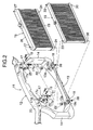
- FIG. 2 is an exploded perspective view of the air conditioning capacitor, the radiator and a bulkhead of the large-sized engine specifications;
- FIG. 3 is a sectional view taken along a line 3-3 in FIG. 1;
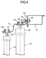
- FIG. 4 is an explanatory view of an operation at the time of mounting the air conditioning capacitor and the radiator;
- FIG. 5 is a perspective view showing the mounting state of an air conditioning capacitor and a radiator of small-sized engine specifications;
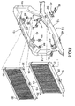
- FIG. 6 is an exploded perspective view of the air conditioning capacitor, the radiator and a bulkhead of the small-sized engine specifications; and
- FIG. 7 is a sectional view taken along a line 7-7 in FIG. 5.
- FIGS. 1 to 4 show a structure in which an
air conditioning capacitor 15 and aradiator 16 are supported at positions forward of a vehicle body as much as possible to secure a space for mounting a large-sized engine in an engine room. - A
bulkhead 11 is disposed at a vehicle body front part of an automobile, and comprises a bulkheadupper part 12 extending in a lateral direction of the vehicle body, a bulkheadlower part 13 extending in the lateral direction of the vehicle body under the bulkheadupper part 12, and a pair of left andright bulkhead sides upper part 12 to left and right opposite end portions of the bulkheadlower part 13. The bulkheadlower part 13 is disposed while being displaced forward of the vehicle body by a distance α, with respect to the bulk head upper 12 (see FIG. 3). - At the
bulkhead 11, theair conditioning capacitor 15 located on the front side of the vehicle body and theradiator 16 located on the rear side of the vehicle body are supported in a state in which theair conditioning capacitor 15 and theradiator 16 are superposed in the longitudinal direction by using twofirst brackets upper part 12, and twosecond brackets lower part 13. Thefirst brackets second brackets - The
first bracket 17 is fixed to a front surface of the bulkheadupper part 12 with twobolts 19 and twonuts 20, extends forward of the vehicle body, and has aradiator support hole 17a formed in its rear portion and an air conditioningcapacitor support hole 17b formed in its front portion. Thesecond bracket 18 is welded 21 to a front surface of the bulkheadlower part 13, extends forward of the vehicle body, and has an air conditioningcapacitor support hole 18a formed in its front portion. - Two
support pins lower tank 23 of theradiator 16 are fitted intorubber bushes radiator support holes 13a which is formed on a top surface of the bulkheadlower part 13. Twosupport pins upper tank 26 of theradiator 16 are fitted intorubber bushes radiator support holes first bracket radiator 16 is supported at thebulkhead 11. - Two
support pins air conditioning capacitor 15 are fitted intorubber bushes capacitor support holes second brackets support pins air conditioning capacitor 15 are fitted intorubber bushes capacitor support holes first brackets air conditioning capacitor 15 is supported at thebulkhead 11. - As a result, as is obvious from FIG. 3, the
radiator 16 is supported on the bulkheadlower part 13 which is located forward of the bulkheadupper part 12, and theair conditioning capacitor 15 is supported further forward of theradiator 16, whereby a space is secured in the engine room behind thebulkhead 11 so that a large-sized engine can be installed therein. - As is obvious from FIG. 2, two bolt holes through which the two
bolts first bracket 17 to the bulkheadupper part 12 are constituted by along hole 17 and acircular hole 17d. When theair conditioning capacitor 15 and theradiator 16 are assembled to thebulkhead 11, thebolt 19 is inserted through only thelong hole 17c of thefirst bracket 17 and temporarily fastened to thenut 20, and theradiator 16 is temporarily supported at therubber bush 22 of the bulkheadlower part 13 and therubber bush 25 of thefirst bracket 17. - Subsequently, as shown in FIG. 4, the
first bracket 17 is slid upward through thelong hole 17c. At this time, therubber bush 25 of thefirst bracket 17 slides upward with respect to thesupport pin 27 of theupper tank 26 of theradiator 16, but does not disengage from thesupport pin 27, and therefore, theradiator 16 does not fall even if theradiator 16 is not held with a hand. In this state, thesupport pin 30 on the undersurface of theair conditioning capacitor 15 is fitted into therubber bush 28 of thesecond bracket 18; thesupport pin 33 on the top surface of thecapacitor 15 is caused to face the lower side of therubber bush 31 of thefirst bracket 17; and then thefirst bracket 17 is slid downward by thelong hole 17c, whereby therubber bush 31 of thefirst bracket 17 is fitted onto thesupport pin 33 on the top surface of theair conditioning capacitor 15, as shown in FIG. 3, to support both theradiator 16 and theair conditioning capacitor 15 on thebulkhead 11. - Finally, the
bolt 19 which has been inserted through thelong hole 17c and temporarily fastened is completely fastened, and the bolt which is inserted through thecircular hole 17d is fastened to thenut 20, thereby completing assembly of theair conditioning capacitor 15 and theradiator 16. - FIGS. 5 to 7 show a structure in which the
air conditioning capacitor 15 and theradiator 16 are supported at positions rearward of the vehicle body as much as possible to prevent damage to theair conditioning capacitor 15 and theradiator 16 at the time of a light collision when a small-sized engine is installed in the engine room. - The
air conditioning capacitor 15 is supported by the bulkheadlower part 13 and a pair ofthird brackets upper part 12. Theradiator 16 is supported by a pair offourth brackets upper part 12 and a pair offifth brackets lower part 13. Thesethird brackets fourth brackets fifth brackets - The
support pins air conditioning capacitor 15 are fitted intorubber bushes capacitor support holes lower part 13. Air conditioning capacitor supportholes third brackets upper part 12 with twobolts nuts support pins air conditioning capacitor 15 are fitted intorubber bushes capacitor support holes air conditioning capacitor 15 is supported above the bulkheadlower part 13. - Radiator support
holes fourth brackets upper part 12 withbolts nuts support pins upper tank 26 are fitted intorubber bushes radiator support holes holes fifth brackets lower part 13. Thesupport pins lower tank 23 of theradiator 16 are fitted intorubber bushes radiator support holes radiator 16 is supported behind theair conditioning capacitor 15. - The
fifth bracket 43 supporting theradiator 16 which is heavy as compared with theair conditioning capacitor 15 includes a reinforcingportion 43b which connects to theradiator support hole 43a and which has a box structure with the bottom surface opened, and a plate-shaped flange portion 43c which connects to the reinforcingportion 43b. At least two spots of the reinforcingportion 43b and theflange portion 43c are welded 52, 53 to the bulkheadlower part 13. The reinforcingportion 43b of the box structure is provided at thefifth bracket 43, and thefifth bracket 43 is welded 52, 53 to the bulkheadlower part 13 at the two spots of the reinforcingportion 43b and theflange 43c, whereby the rigidity of thefifth bracket 43 is enhanced to firmly support theradiator 16. - As described above, when the
air conditioning capacitor 15 and theradiator 16 are supported at the positions forward with respect to thebulkhead 11 in order to avoid interference with the engine, the first bracket group comprising the first and thesecond brackets air conditioning capacitor 15 and theradiator 16 are supported at the positions rearward with respect to thebulkhead 11 in order to prevent damage to theair conditioning capacitor 15 and theradiator 16 at the time of a light collision, the second bracket group comprising the third tofifth brackets air conditioning capacitor 15 and theradiator 16 in the longitudinal direction while using thecommon bulkhead 11. - The embodiment of the present invention is described thus far, but the present invention is not limited to the above described embodiment, and various design changes can be made without departing from the present invention described in claims.
Claims (3)
- A vehicle body front part structure of an automobile in which an air conditioning capacitor (15) provided on a front side and a radiator (16) provided on a rear side are superposed in a longitudinal direction and supported on a bulkhead (11) disposed at a front part of a vehicle body,
characterized in that a first bracket group is used when the air conditioning capacitor (15) and the radiator (16) are supported at positions forward with respect to the bulkhead (11), and a second bracket group is used when the air conditioning capacitor (15) and the radiator (16) are supported at positions rearward with respect to the bulkhead (11). - The vehicle body front part structure of an automobile according to claim 1, characterized in
that the bulkhead (11) includes a bulkhead upper part (12) and a bulkhead lower part (13) which is located forward of the bulkhead upper part (12);
that the first bracket group comprises a first bracket (17) which supports upper ends of the air conditioning capacitor (15) and the radiator (16) at positions forward of the bulkhead upper part (12), and a second bracket (18) which supports a lower end of the air conditioning capacitor (15) at a position forward of the bulkhead lower part (13); and
that the second bracket group comprises a third bracket (41) which supports the upper end of the air conditioning capacitor (15) at a position forward of the bulkhead upper part (12), a fourth bracket (42) which supports the upper end of the radiator (16) at a position rearward of the bulkhead upper part (12), and a fifth bracket (43) which supports a lower end of the radiator (16) rearward of the bulkhead lower part (13). - The vehicle body front part structure of an automobile according to claim 2, characterized in that the fifth bracket (43) includes a radiator support portion (43a) that supports the lower end of the radiator (16), a reinforcing portion (43b) of a box structure that connects to the radiator support portion (43a), and a plate-shaped flange portion (43c) that connects to the reinforcing portion (43b), and the fifth bracket (43) is fixed to the bulkhead lower part (13) in at least the reinforcing portion (43b) and the flange portion (43c).
Applications Claiming Priority (1)
| Application Number | Priority Date | Filing Date | Title |
|---|---|---|---|
| JP2005149889A JP4292171B2 (en) | 2005-05-23 | 2005-05-23 | Front body structure of automobile |
Publications (2)
| Publication Number | Publication Date |
|---|---|
| EP1726470A1 true EP1726470A1 (en) | 2006-11-29 |
| EP1726470B1 EP1726470B1 (en) | 2009-08-12 |
Family
ID=36926838
Family Applications (1)
| Application Number | Title | Priority Date | Filing Date |
|---|---|---|---|
| EP20060252671 Not-in-force EP1726470B1 (en) | 2005-05-23 | 2006-05-23 | Vehicle body front part structure of automobile |
Country Status (4)
| Country | Link |
|---|---|
| EP (1) | EP1726470B1 (en) |
| JP (1) | JP4292171B2 (en) |
| CN (1) | CN100410096C (en) |
| DE (1) | DE602006008380D1 (en) |
Cited By (10)
| Publication number | Priority date | Publication date | Assignee | Title |
|---|---|---|---|---|
| EP2113408A1 (en) * | 2008-04-28 | 2009-11-04 | Toyoda Iron Works Co., Ltd. | Vehicular cooling device supporting apparatus |
| WO2010004422A3 (en) * | 2008-07-08 | 2010-11-25 | Toyota Jidosha Kabushiki Kaisha | Cooling conduit arrangement for hybrib vehicle with two radiators |
| FR3022211A1 (en) * | 2014-06-16 | 2015-12-18 | Renault Sas | ASSEMBLY OF A MOTOR VEHICLE STRUCTURE ELEMENT AND A FUNCTIONAL ELEMENT |
| WO2016102169A1 (en) * | 2014-12-22 | 2016-06-30 | Volkswagen Aktiengesellschaft | Series of mounting supports and mounting support for fastening radiator modules and method for producing mounting supports |
| FR3045511A1 (en) * | 2015-12-18 | 2017-06-23 | Renault Sas | FIXING A COOLING MODULE ON A TECHNICAL FRONT PANEL. |
| DE102016211005A1 (en) | 2016-06-21 | 2017-12-21 | Volkswagen Aktiengesellschaft | Radiator bearing for a lower bearing journal of a radiator module, frame-like mounting support for mounting motor vehicle radiator modules and arrangement of a radiator bearing in a lower horizontal support of a mounting bracket |
| DE102016211059A1 (en) | 2016-06-21 | 2017-12-21 | Volkswagen Aktiengesellschaft | System for mounting radiator modules with at least one journal in an upper portion of a mounting bracket of a motor vehicle and intermediate element for receiving a radiator bearing of a radiator module |
| FR3093982A1 (en) * | 2019-03-21 | 2020-09-25 | Renault S.A.S | Cooling assembly for a motor vehicle |
| US20220212724A1 (en) * | 2021-01-06 | 2022-07-07 | Hyundai Motor Company | Radiator support assembly |
| US11904679B2 (en) | 2021-06-22 | 2024-02-20 | Toyota Jidosha Kabushiki Kaisha | Electric vehicle cooling system |
Families Citing this family (8)
| Publication number | Priority date | Publication date | Assignee | Title |
|---|---|---|---|---|
| WO2011152125A1 (en) * | 2010-05-31 | 2011-12-08 | スズキ株式会社 | Structure for front part of vehicle |
| KR101672033B1 (en) * | 2010-09-17 | 2016-11-02 | 현대모비스 주식회사 | Compatibility carrier for vehicle |
| CN103209884B (en) * | 2010-11-19 | 2015-08-12 | 铃木株式会社 | The structure of Vehicular body front |
| JP5853629B2 (en) * | 2011-11-21 | 2016-02-09 | スズキ株式会社 | Body structure |
| JP2013133031A (en) * | 2011-12-27 | 2013-07-08 | Honda Motor Co Ltd | Vehicle-body front structure |
| JP2014125069A (en) * | 2012-12-26 | 2014-07-07 | Suzuki Motor Corp | Heat exchanger suspension structure of resin front end |
| JP7001644B2 (en) * | 2019-07-23 | 2022-01-19 | 本田技研工業株式会社 | Body front structure |
| CN110877513A (en) * | 2019-12-05 | 2020-03-13 | 安徽江淮汽车集团股份有限公司 | Fixing structure of electric automobile condenser |
Citations (6)
| Publication number | Priority date | Publication date | Assignee | Title |
|---|---|---|---|---|
| EP0178266A1 (en) * | 1984-10-01 | 1986-04-16 | FIAT AUTO S.p.A. | Motor vehicle including a preassembled subassembly formed by the power unit and a series of components of the systems of the vehicle |
| JPH0478774A (en) * | 1990-07-19 | 1992-03-12 | Mazda Motor Corp | Front body structure of automobile |
| US5271473A (en) * | 1991-12-18 | 1993-12-21 | Mazda Motor Corporation | Front body structure for automotive vehicle |
| JP2000025466A (en) * | 1998-07-14 | 2000-01-25 | Suzuki Motor Corp | Mounting structure of condenser for radiator and air conditioner |
| US20020056541A1 (en) * | 2000-09-07 | 2002-05-16 | Hiroshi Kokubunji | Mounting structure for heat exchanger and duplex heat exchanger |
| JP2004338668A (en) * | 2003-05-19 | 2004-12-02 | Aisin Seiki Co Ltd | Radiator unit |
Family Cites Families (5)
| Publication number | Priority date | Publication date | Assignee | Title |
|---|---|---|---|---|
| JPS5941864Y2 (en) * | 1979-11-16 | 1984-12-04 | 日産自動車株式会社 | Support structure for heat exchangers, etc. |
| JPS59202937A (en) * | 1983-05-04 | 1984-11-16 | Nissan Motor Co Ltd | Attaching structure of condenser and radiator for vehicle |
| JP2605818B2 (en) * | 1988-08-30 | 1997-04-30 | スズキ株式会社 | Mounting device for radiators |
| JPH07101253A (en) * | 1993-10-01 | 1995-04-18 | Mazda Motor Corp | Car front structure |
| JP2000025650A (en) * | 1998-07-16 | 2000-01-25 | Suzuki Motor Corp | Body front structure |
-
2005
- 2005-05-23 JP JP2005149889A patent/JP4292171B2/en not_active Expired - Fee Related
-
2006
- 2006-05-23 CN CNB200610080951XA patent/CN100410096C/en not_active Expired - Fee Related
- 2006-05-23 DE DE200660008380 patent/DE602006008380D1/en active Active
- 2006-05-23 EP EP20060252671 patent/EP1726470B1/en not_active Not-in-force
Patent Citations (6)
| Publication number | Priority date | Publication date | Assignee | Title |
|---|---|---|---|---|
| EP0178266A1 (en) * | 1984-10-01 | 1986-04-16 | FIAT AUTO S.p.A. | Motor vehicle including a preassembled subassembly formed by the power unit and a series of components of the systems of the vehicle |
| JPH0478774A (en) * | 1990-07-19 | 1992-03-12 | Mazda Motor Corp | Front body structure of automobile |
| US5271473A (en) * | 1991-12-18 | 1993-12-21 | Mazda Motor Corporation | Front body structure for automotive vehicle |
| JP2000025466A (en) * | 1998-07-14 | 2000-01-25 | Suzuki Motor Corp | Mounting structure of condenser for radiator and air conditioner |
| US20020056541A1 (en) * | 2000-09-07 | 2002-05-16 | Hiroshi Kokubunji | Mounting structure for heat exchanger and duplex heat exchanger |
| JP2004338668A (en) * | 2003-05-19 | 2004-12-02 | Aisin Seiki Co Ltd | Radiator unit |
Non-Patent Citations (3)
| Title |
|---|
| PATENT ABSTRACTS OF JAPAN vol. 016, no. 293 (M - 1273) 29 June 1992 (1992-06-29) * |
| PATENT ABSTRACTS OF JAPAN vol. 2000, no. 04 31 August 2000 (2000-08-31) * |
| PATENT ABSTRACTS OF JAPAN vol. 2003, no. 12 5 December 2003 (2003-12-05) * |
Cited By (18)
| Publication number | Priority date | Publication date | Assignee | Title |
|---|---|---|---|---|
| EP2113408A1 (en) * | 2008-04-28 | 2009-11-04 | Toyoda Iron Works Co., Ltd. | Vehicular cooling device supporting apparatus |
| WO2010004422A3 (en) * | 2008-07-08 | 2010-11-25 | Toyota Jidosha Kabushiki Kaisha | Cooling conduit arrangement for hybrib vehicle with two radiators |
| CN102089172A (en) * | 2008-07-08 | 2011-06-08 | 丰田自动车株式会社 | Hybrid vehicle |
| US8020656B2 (en) | 2008-07-08 | 2011-09-20 | Toyota Jidosha Kabushiki Kaisha | Cooling conduit arrangement for hybrid vehicle with two radiators |
| CN102089172B (en) * | 2008-07-08 | 2013-09-25 | 丰田自动车株式会社 | Hybrid vehicle |
| CN106660592A (en) * | 2014-06-16 | 2017-05-10 | 雷诺股份公司 | Assembly of a structural element of a motor vehicle and a functional element |
| WO2015193596A1 (en) * | 2014-06-16 | 2015-12-23 | Renault S.A.S. | Assembly of a structural element of a motor vehicle and a functional element |
| FR3022211A1 (en) * | 2014-06-16 | 2015-12-18 | Renault Sas | ASSEMBLY OF A MOTOR VEHICLE STRUCTURE ELEMENT AND A FUNCTIONAL ELEMENT |
| CN106660592B (en) * | 2014-06-16 | 2018-10-12 | 雷诺股份公司 | The component of motor vehicle construction element and function element |
| WO2016102169A1 (en) * | 2014-12-22 | 2016-06-30 | Volkswagen Aktiengesellschaft | Series of mounting supports and mounting support for fastening radiator modules and method for producing mounting supports |
| US10358027B2 (en) | 2014-12-22 | 2019-07-23 | Volkswagen Aktiengesellschaft | Series of mounting supports and mounting support for fastening radiator modules, and method for manufacturing mounting supports |
| FR3045511A1 (en) * | 2015-12-18 | 2017-06-23 | Renault Sas | FIXING A COOLING MODULE ON A TECHNICAL FRONT PANEL. |
| DE102016211005A1 (en) | 2016-06-21 | 2017-12-21 | Volkswagen Aktiengesellschaft | Radiator bearing for a lower bearing journal of a radiator module, frame-like mounting support for mounting motor vehicle radiator modules and arrangement of a radiator bearing in a lower horizontal support of a mounting bracket |
| DE102016211059A1 (en) | 2016-06-21 | 2017-12-21 | Volkswagen Aktiengesellschaft | System for mounting radiator modules with at least one journal in an upper portion of a mounting bracket of a motor vehicle and intermediate element for receiving a radiator bearing of a radiator module |
| FR3093982A1 (en) * | 2019-03-21 | 2020-09-25 | Renault S.A.S | Cooling assembly for a motor vehicle |
| US20220212724A1 (en) * | 2021-01-06 | 2022-07-07 | Hyundai Motor Company | Radiator support assembly |
| US11613311B2 (en) * | 2021-01-06 | 2023-03-28 | Hyundai Motor Company | Radiator support assembly |
| US11904679B2 (en) | 2021-06-22 | 2024-02-20 | Toyota Jidosha Kabushiki Kaisha | Electric vehicle cooling system |
Also Published As
| Publication number | Publication date |
|---|---|
| EP1726470B1 (en) | 2009-08-12 |
| CN1868778A (en) | 2006-11-29 |
| DE602006008380D1 (en) | 2009-09-24 |
| JP4292171B2 (en) | 2009-07-08 |
| JP2006327259A (en) | 2006-12-07 |
| CN100410096C (en) | 2008-08-13 |
Similar Documents
| Publication | Publication Date | Title |
|---|---|---|
| EP1726470A1 (en) | Vehicle body front part structure of automobile | |
| US7461890B2 (en) | Vehicle front body structure | |
| US7644966B2 (en) | Vehicle bumper fascia retainer | |
| US7267394B1 (en) | Front end tubular structure for unitized body vehicles | |
| US7651133B2 (en) | Frame extender | |
| US6948769B2 (en) | Vehicle front end structure | |
| JP2012201158A (en) | Working vehicle | |
| JP2008195094A (en) | Vehicle front structure | |
| JP5794923B2 (en) | Bracket for vehicle | |
| JP2010095031A (en) | Vehicle body front structure | |
| US7185724B2 (en) | Battery support structure | |
| JP4099781B2 (en) | Vehicle tow hook arrangement structure | |
| JP7032203B2 (en) | Body for work vehicle | |
| JP4293620B2 (en) | Pedal structure | |
| JP4168826B2 (en) | Automotive engine mount structure | |
| JP4032818B2 (en) | Front body structure of automobile and method for assembling front part of vehicle body | |
| JP2005219590A (en) | Front end module mounting structure on the front | |
| JP6459031B2 (en) | Underrun protector mounting structure and underrun protector bracket | |
| JP4233041B2 (en) | Body front structure | |
| JP7356649B2 (en) | wiper bracket | |
| JP6459032B2 (en) | Underrun protector mounting structure and underrun protector bracket | |
| JP2006224878A (en) | Parts mounting structure in the motor room | |
| JP2012166700A (en) | Negative pressure supply device of vehicle | |
| JPS60996Y2 (en) | Structure of the headlamp bracket attached to the bonnet | |
| KR200290566Y1 (en) | Sub-frame for automobile |
Legal Events
| Date | Code | Title | Description |
|---|---|---|---|
| PUAI | Public reference made under article 153(3) epc to a published international application that has entered the european phase |
Free format text: ORIGINAL CODE: 0009012 |
|
| AK | Designated contracting states |
Kind code of ref document: A1 Designated state(s): AT BE BG CH CY CZ DE DK EE ES FI FR GB GR HU IE IS IT LI LT LU LV MC NL PL PT RO SE SI SK TR |
|
| AX | Request for extension of the european patent |
Extension state: AL BA HR MK YU |
|
| 17P | Request for examination filed |
Effective date: 20061102 |
|
| 17Q | First examination report despatched |
Effective date: 20070116 |
|
| AKX | Designation fees paid |
Designated state(s): DE GB |
|
| GRAP | Despatch of communication of intention to grant a patent |
Free format text: ORIGINAL CODE: EPIDOSNIGR1 |
|
| GRAS | Grant fee paid |
Free format text: ORIGINAL CODE: EPIDOSNIGR3 |
|
| GRAA | (expected) grant |
Free format text: ORIGINAL CODE: 0009210 |
|
| AK | Designated contracting states |
Kind code of ref document: B1 Designated state(s): DE GB |
|
| REG | Reference to a national code |
Ref country code: GB Ref legal event code: FG4D |
|
| REF | Corresponds to: |
Ref document number: 602006008380 Country of ref document: DE Date of ref document: 20090924 Kind code of ref document: P |
|
| PLBE | No opposition filed within time limit |
Free format text: ORIGINAL CODE: 0009261 |
|
| STAA | Information on the status of an ep patent application or granted ep patent |
Free format text: STATUS: NO OPPOSITION FILED WITHIN TIME LIMIT |
|
| 26N | No opposition filed |
Effective date: 20100517 |
|
| PGFP | Annual fee paid to national office [announced via postgrant information from national office to epo] |
Ref country code: GB Payment date: 20130522 Year of fee payment: 8 Ref country code: DE Payment date: 20130515 Year of fee payment: 8 |
|
| REG | Reference to a national code |
Ref country code: DE Ref legal event code: R119 Ref document number: 602006008380 Country of ref document: DE |
|
| GBPC | Gb: european patent ceased through non-payment of renewal fee |
Effective date: 20140523 |
|
| REG | Reference to a national code |
Ref country code: DE Ref legal event code: R119 Ref document number: 602006008380 Country of ref document: DE Effective date: 20141202 |
|
| PG25 | Lapsed in a contracting state [announced via postgrant information from national office to epo] |
Ref country code: DE Free format text: LAPSE BECAUSE OF NON-PAYMENT OF DUE FEES Effective date: 20141202 |
|
| PG25 | Lapsed in a contracting state [announced via postgrant information from national office to epo] |
Ref country code: GB Free format text: LAPSE BECAUSE OF NON-PAYMENT OF DUE FEES Effective date: 20140523 |