EP1726447B1 - Drucktisch für Flachbettdruckmaschinen - Google Patents
Drucktisch für Flachbettdruckmaschinen Download PDFInfo
- Publication number
- EP1726447B1 EP1726447B1 EP05011312A EP05011312A EP1726447B1 EP 1726447 B1 EP1726447 B1 EP 1726447B1 EP 05011312 A EP05011312 A EP 05011312A EP 05011312 A EP05011312 A EP 05011312A EP 1726447 B1 EP1726447 B1 EP 1726447B1
- Authority
- EP
- European Patent Office
- Prior art keywords
- printing table
- channels
- printing
- channel
- intermediate plate
- Prior art date
- Legal status (The legal status is an assumption and is not a legal conclusion. Google has not performed a legal analysis and makes no representation as to the accuracy of the status listed.)
- Expired - Lifetime
Links
Images



Classifications
-
- B—PERFORMING OPERATIONS; TRANSPORTING
- B41—PRINTING; LINING MACHINES; TYPEWRITERS; STAMPS
- B41J—TYPEWRITERS; SELECTIVE PRINTING MECHANISMS, i.e. MECHANISMS PRINTING OTHERWISE THAN FROM A FORME; CORRECTION OF TYPOGRAPHICAL ERRORS
- B41J11/00—Devices or arrangements of selective printing mechanisms, e.g. ink-jet printers or thermal printers, for supporting or handling copy material in sheet or web form
- B41J11/02—Platens
- B41J11/06—Flat page-size platens or smaller flat platens having a greater size than line-size platens
Definitions
- the invention relates to a printing table for flatbed printing machines according to the preamble of claim 1.
- a printing table is from the document JP 2005 096374 known.
- digital flatbed printing machines place high demands on the flatness of a printing table, since, for example, an inkjet print head has to be guided at a constant distance of about one millimeter over a printing table surface in order to achieve a good printed image. While this can still be achieved comparatively easily with small-format printing tables, care must be taken with large-format printing tables, for example two by three meters, that temperature fluctuations on or in the printing table do not lead to deformations of the printing table.
- a printing table for flatbed printing machines is to be created, which is insensitive to temperature fluctuations.
- a printing table for flatbed printing machines is provided with a pressure table top plate, a pressure plate bottom plate and arranged between pressure table top and pressure plate bottom plate pressure table intermediate plate, wherein the pressure table intermediate plate is provided with channels for carrying coolant.
- a printing table with sufficient mechanical rigidity can be provided, in which, on the other hand, the coolant can be guided very close to the printing table surface, so that the area immediately adjacent to the printing table surface is also kept at a constant temperature can be.
- a perpendicular to the printing table surface symmetrical structure is chosen, so that in principle no tensions of the printing table are to be feared by different expansion of pressure table top plate and pressure plate bottom plate.
- the pressure table intermediate plate parallel to each other and regularly spaced channels, with only a portion of the channels is provided for the passage of coolant.
- every second channel is provided for the passage of coolant.
- the channels can be closely adjacent to each other, so that a mechanically rigid design of the printing table is achieved and yet material accumulations, which are always problematic with respect to thermal heating, can be avoided between the coolant channels.
- material accumulations which are always problematic with respect to thermal heating, can be avoided between the coolant channels.
- not all channels have to be used for the passage of coolant, so that depending on the application, simple and low-loss coolant ducts can be realized.
- the printing table intermediate plate is formed from a plurality of adjacently arranged extruded profiles.
- aluminum extruded profiles are provided which can be produced inexpensively on the one hand with high dimensional precision and on the other hand have a very good thermal conductivity.
- a modular structure is created, so that printing tables in different grid sizes can be produced.
- the channels are formed within the extruded profiles.
- the channels can contribute to the rigidity of the extruded professional and there are no leaks over the length of the extruded profiles to be feared.
- the printing table intermediate plate is glued to the printing table top plate and / or the printing table bottom plate.
- Bonding creates a very stable and stiff sandwich structure, which makes it possible to produce even very large printing tables with the required flatness.
- a plurality of strip-like and mutually parallel adhesive surfaces between printing table intermediate plate, printing table top plate and / or printing plate bottom plate are provided.
- the stiff adhesive surfaces extend above and / or below only a part of the channels.
- the strip-like adhesive surfaces extend above and / or below each second channel.
- the strip-like adhesive surfaces do not extend above and / or below coolant-carrying channels in the printing table intermediate plate.
- grooves for receiving adhesive in the printing table intermediate plate, the printing table top plate and / or printing plate bottom plate are provided on both sides of the strip-like adhesive surfaces.
- grooves for receiving adhesive can be ensured that the strip-like adhesive surfaces remain limited to the areas between the grooves and excess adhesive does not continue to flow in the area above the coolant channels. In addition, it can be ensured that excess adhesive can escape and does not lead to unevenness of the printing table surface.
- the direction of flow between successive channels provided for coolant is directed oppositely perpendicular to the longitudinal direction of the channels.
- channels provided for coolant branch with the same flow direction one after the other from a feed collecting channel extending perpendicularly to the longitudinal direction of the channels and open one after the other into a drain collecting channel extending perpendicularly to the longitudinal direction of the channels, so that a flow path from a beginning of the feed collecting channel to one end of the Drain collection channel for all provided for coolant channels with the same flow direction is the same length.
- vacuum bores are provided which pass through the printing table top plate, the printing table intermediate plate and the printing plate bottom plate.
- Such vacuum holes are provided for holding a medium to be printed. Particularly in the case of digital flatbed printing machines, it must be ensured that the medium to be printed rests on the entire surface of the printing table surface so that unevennesses in the surface to be printed are not produced by the medium to be printed. For this purpose, the medium to be printed can be sucked by means of negative pressure.
- the printing table structure according to the invention with channels in the pressure table intermediate plate for carrying out coolant opens up the possibility of performing vacuum holes between the channels in the printing table intermediate plate substantially perpendicular to the channels through the printing table top plate, the printing table intermediate plate and the printing table bottom plate. Alternatively, channels in the pressure table intermediate plate could be used for the application of negative pressure.
- FIG. 1 an inventive printing table 10 is shown in plan view.
- the printing table 10 has a flat surface, of numerous and in the Fig. 1 only partially illustrated vacuum holes 12 is interspersed.
- vacuum holes 12 By means of the vacuum holes 12, with the exception of in Fig. 1
- Right and left edge regions are distributed uniformly over substantially the entire surface of the printing table 10, a lying on the printing table 10, to be printed medium, such as a paper sheet, are sucked against the printing table surface. This can ensure that the medium to be printed rests over the entire surface of the printing table surface.
- inkjet printheads must be performed at a constant distance of about one millimeter on the medium to be printed in order to achieve a precise print image.
- Fig. 1 of the printing table 10 can be seen at the right and left edge channel components 16a, 16b.
- These channel components 16a, 16b each have two channel bores which serve for the supply and removal of coolant to and from the printing table 10.
- Fig. 3 In the presentation of the Fig. 3 is the sectional view along the line EE of Fig. 1 represented and how Fig. 3 can be seen, the cutting plane passes through one of the channels in the channel member 16b.
- branch ducts in the direction of the printing table 10 depart from the channels in the channel component 16b in order to supply coolant to channels arranged in the printing table 10.
- the channels of the channel components 16a, 16b are accessible from below the pressure table 10 at their front and rear ends and can be connected to coolant lines.
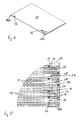
- FIG. 4 shows a perspective view of the printing table 10, wherein as in Fig. 1 only a portion of the vacuum holes 12 is shown. In the view of Fig. 4 the channel components 16a, 16b can be seen.
- FIG. 5 shows in an enlarged view the detail V of Fig. 1 .
- components or components that in the plan view of Fig. 5 in and of itself would not be recognizable, shown in dashed lines.
- Corresponding Fig. 1 are in the top view of Fig. 5 in and of itself only the opening in the pressure table surface vacuum holes 12, which also opens in the printing table surface opening holes 14 for mounting screws and other holes 18. Also visible is the end of the channel member 16b.
- dashed lines show coolant channels in the pressure table 10 as well as the coolant channels and branch channels 24, 28 in the channel component 16b. Furthermore, it can be seen that at the end faces of the channel member 16b and in the same manner, not shown, also on the channel component 16a, end pieces are fastened by means of bolts, wherein the end pieces cause a diversion of the coolant flow by 90 ° downwards.
- the channel component 16b has a first coolant channel 20, which is provided, for example, for the supply of coolant. Parallel to the first coolant channel 20 extends in the channel member 16b, a second coolant channel 22, which is provided for example for the removal of coolant. Via a branch channel 24, the first coolant channel 20 communicates with a channel 26 in the pressure table intermediate plate 32.
- the second coolant channel 22 is above a similar, in Fig. 6 unrecognizable branch channel with a parallel to the channel 26 extending channel in conjunction.
- branch channels 24 are connected to every fourth channel in the printing table intermediate plate 32 and in the same way from the channel 22 outgoing branch channels 28 are connected to every fourth channel in the printing table intermediate plate 32. Thus, only every other channel is used for the passage of coolant.
- Coolant supplied via the first coolant channel 20 in the channel component 16b thereby passes into channels 26 in the pressure table intermediate plate 32, is guided through the channels 26 to the opposite channel component 16a and is discharged there again via one of two coolant channels extending parallel to one another.
- coolant supplied via the first coolant channel 20 in the channel component 16b thereby passes into channels 26 in the pressure table intermediate plate 32, is guided through the channels 26 to the opposite channel component 16a and is discharged there again via one of two coolant channels extending parallel to one another.
- coolant is passed through channels 26 different channels through the pressure table, passes through branch channels 28 then into the coolant channel 22 in the channel member 16b and is discharged through this.
- the printing table 10 has a printing table top plate 30, a printing table intermediate plate 32 and a printing table bottom plate 34.
- the printing table cover plate 30 is formed as a solid plate, for example made of aluminum.
- the printing table bottom plate 34 is formed as a solid plate, for example made of aluminum.
- the pressure table intermediate plate 32 consists of a plurality of juxtaposed aluminum extruded profiles 32a, 32b, which are provided with mutually parallel channels 26, 36, 38, 40, 48. Already in Fig. 6 was to recognize the channel 26, which is fed via the branch channel 24 from the coolant passage 20 with coolant. Based on Fig.
- a branch channel 28 which starts from the second coolant channel 22
- two further channels 38, 40 are arranged in the extruded profile 32 a, which are not supplied with coolant and consequently are not connected to the first or second coolant channel 20, 22.
- branch channels 28 then connect a in Fig. 7 Channel no longer shown in the extruded profile 32b with the second coolant channel 22, so that seen over the entire width of the pressure table 10, in each case a channel 36 in each extruded profile 32a, 32b with the second coolant channel 22 is in communication.
- one channel 26 of all extruded profiles 32a, 32b is connected to the first coolant channel 20 via a respective branch channel 24.
- An analogous arrangement is found in the region of the coolant channel component 16a.
- the schematic representation of the Fig. 8 to recognize that regardless of whether it flows through the channels 26 or 36 and irrespective of which of the channels 26, 36 it flows through, the coolant always has to cover the same distance. Because the channels 26, which all have the same direction of flow, branch off from an inlet collecting channel 42 extending perpendicularly to the longitudinal direction of the channels 26 and open one after another in the discharge collecting channel 20 extending perpendicularly to the longitudinal direction of the channels. Analogously, the channels 36 branch one after the other As a result, it can be ensured that the same flow losses occur in all channels 26, 36, and thus all the channels 26, 36 are flowed through by the same amount of coolant in the same time.
- the end face of the channel member 16b is provided with an end piece 46, by means of which a deflection of the flow direction of the channels 20, 22 is effected by 90 °.
- the end piece 46 is by means of in Fig. 7 unrecognizable bolt connected to the channel member 16b and sealed against this by means not shown sealing rings in sealing grooves 48.
- the printing table cover plate 30 is bonded to the extruded profile 32a of the printing table intermediate plate 32 by means of strip-shaped adhesive surfaces above the channels 38, 40.
- the printing table plate 32 is glued to the printing table bottom plate 34 via strip-shaped adhesive surfaces below the channels 38, 40.
- the strip-shaped adhesive surfaces above or below the channel 48 can be seen. The strip-shaped adhesive surfaces are thus seen over the length of the printing table thus arranged only above or below each second channel 38, 40, 48 and beyond only above or below channels 38, 40, 48 are arranged, which do not lead coolant.
- the strip-shaped adhesive surfaces are limited by adhesive grooves 50 in the extruded profiles 32a, 32b. In the adhesive grooves 50 excess adhesive can occur, so that on the one hand, the adhesive surfaces are clearly limited and on the other hand, excess adhesive can not lead to unevenness of the surface of the printing table 10.
Landscapes
- Handling Of Sheets (AREA)
- Manufacturing Of Printed Wiring (AREA)
- Screen Printers (AREA)
- Rotary Presses (AREA)
Description
- Die Erfindung betrifft einen Drucktisch für Flachbettdruckmaschinen nach dem Oberbegriff des Anspruchs 1. Ein solcher Drucktisch ist aus dem Dokument
JP 2005 096374 - Insbesondere digitale Flachbettdruckmaschinen stellen hohe Anforderungen an die Ebenheit eines Drucktisches, da beispielsweise ein Tintenstrahldruckkopf in konstantem Abstand von etwa einem Millimeter über einer Drucktischoberfläche geführt werden muss, um ein gutes Druckbild zu erreichen. Während dies bei kleinformatigen Drucktischen noch vergleichsweise problemlos erreichbar ist, muss bei großformatigen Drucktischen, beispielsweise zwei mal drei Meter, dafür Sorge getragen werden, dass Temperaturschwankungen am oder im Drucktisch nicht zu Verformungen des Drucktisches führen.
- Mit der Erfindung soll ein Drucktisch für Flachbettdruckmaschinen geschaffen werden, der unempfindlich gegenüber Temperaturschwankungen ist.
- Erfindungsgemäß ist hierzu ein Drucktisch für Flachbettdruckmaschinen mit einer Drucktischdeckplatte, einer Drucktischbodenplatte und einer zwischen Drucktischdeckplatte und Drucktischbodenplatte angeordneten Drucktischzwischenplatte vorgesehen, bei dem die Drucktischzwischenplatte mit Kanälen zum Durchführen von Kühlmittel versehen ist.
- Mittels einer solchen Sandwichkonstruktion kann zum einen auch bei geringer Dicke ein Drucktisch mit ausreichender mechanischer Steifheit geschaffen werden, bei dem zum anderen das Kühlmittel sehr nahe an der Drucktischoberfläche geführt werden kann, so dass auch der unmittelbar an die Drucktischoberfläche angrenzende Bereich auf einer konstanten Temperatur gehalten werden kann. Zweckmäßigerweise wird ein senkrecht zur Drucktischoberfläche symmetrischer Aufbau gewählt, so dass bereits prinzipbedingt keine Verspannungen des Drucktisches durch unterschiedliche Ausdehnung von Drucktischdeckplatte und Drucktischbodenplatte zu befürchten sind.
- In Weiterbildung der Erfindung weist die Drucktischzwischenplatte parallel zueinander verlaufende und regelmäßig voneinander beabstandete Kanäle auf, wobei nur ein Teil der Kanäle für das Durchführen von Kühlmittel vorgesehen ist. Vorteilhafterweise ist jeder zweite Kanal für das Durchführen von Kühlmittel vorgesehen.
- Auf diese Weise können die Kanäle eng zueinander benachbart sein, so dass eine mechanisch steife Ausbildung des Drucktisches erreicht wird und dennoch Materialanhäufungen, die bezüglich thermischer Erwärmung stets problematisch sind, zwischen den Kühlmittelkanälen vermieden werden können. Trotz des Vorsehens zahlreicher Kanäle müssen nicht alle Kanäle für das Durchführen von Kühlmittel genutzt werden, so dass sich je nach Anwendungsfall einfache und verlustarme Kühlmittelführungen realisieren lassen.
- In Weiterbildung der Erfindung ist die Drucktischzwischenplatte aus mehreren nebeneinander angeordneten Strangpressprofilen gebildet.
- Beispielsweise sind Aluminiumstrangpressprofile vorgesehen, die einerseits mit hoher maßlicher Präzision kostengünstig hergestellt werden können und andererseits eine sehr gute thermische Leitfähigkeit aufweisen. Durch Anordnen mehrerer Strangpressprofile nebeneinander wird ein modularer Aufbau geschaffen, so dass Drucktische in unterschiedlichen Rastergrößen hergestellt werden können.
- In Weiterbildung der Erfindung sind die Kanäle innerhalb der Strangpressprofile ausgebildet.
- Auf diese Weise können die Kanäle zur Steifigkeit des Strangpressprofis beitragen und es sind keine Leckagen über die Länge der Strangpressprofile zu befürchten.
- In Weiterbildung der Erfindung ist die Drucktischzwischenplatte mit der Drucktischdeckplatte und/oder der Drucktischbodenplatte verklebt.
- Durch Verkleben entsteht eine sehr stabile und steife Sandwichstruktur, die es ermöglicht, auch sehr große Drucktische mit der geforderten Ebenheit herzustellen.
- In Weiterbildung der Erfindung sind mehrere streifenartige und parallel zueinander verlaufende Klebeflächen zwischen Drucktischzwischenplatte, Drucktischdeckplatte und/oder Drucktischbodenplatte vorgesehen.
- Indem lediglich streifenartige und parallel zueinander verlaufende Klebeflächen vorgesehen sind, wird ein Wärmeübergang zwischen der Drucktischzwischenplatte, der Drucktischdeckplatte und/oder der Drucktischbodenplatte verbessert, da Klebstoff in der Regel schlechte Wärmeleiteigenschaften aufweist. Wird nun dafür Sorge getragen, dass die Drucktischzwischenplatte in den Zwischenräumen zwischen den Klebeflächen an der Drucktischdeckplatte und/oder der Drucktischbodenplatte anliegt, so kann in diesen Bereichen ein deutlich besserer Wärmeübergang, verglichen mit den Klebeflächen, erreicht werden. Dennoch wird eine großflächige Verklebung erzielt.
- In Weiterbildung der Erfindung verlaufen die steifenartigen Klebeflächen oberhalb und/oder unterhalb lediglich eines Teils der Kanäle. Vorteilhafterweise verlaufen die streifenartigen Klebeflächen oberhalb und/oder unterhalb jedes zweiten Kanals. Vorteilhafterweise verlaufen die streifenartigen Klebeflächen nicht oberhalb und/oder unterhalb von kühlmittelführenden Kanälen in der Drucktischzwischenplatte.
- Durch diese Maßnahmen wird insbesondere oberhalb und/oder unterhalb der kühlmittelführenden Kanäle ein besonders guter Wärmeübergang zur Drucktischbodenplatte bzw. Drucktischdeckplatte erreicht, da speziell in diesen Bereichen keine Klebstoffzwischenschicht vorhanden ist, die den Wärmeübergang verschlechtern könnte.
- In Weiterbildung der Erfindung sind zu beiden Seiten der streifenartigen Klebeflächen Nuten zum Aufnehmen von Klebstoff in der Drucktischzwischenplatte, der Drucktischdeckplatte und/oder Drucktischbodenplatte vorgesehen.
- Durch Nuten zum Aufnehmen von Klebstoff kann sichergestellt werden, dass die streifenartigen Klebeflächen auf die Bereiche zwischen den Nuten beschränkt bleiben und überschüssiger Klebstoff nicht in den Bereich oberhalb der Kühlmittelkanäle weiter fließt. Darüber hinaus kann sichergestellt werden, dass überschüssiger Klebstoff ausweichen kann und nicht zu Unebenheiten der Drucktischoberfläche führt.
- In Weiterbildung der Erfindung ist senkrecht zur Längsrichtung der Kanäle gesehen die Strömungsrichtung zwischen aufeinanderfolgenden, für Kühlmittel vorgesehene Kanäle entgegengesetzt gerichtet.
- Auf diese Weise wird eine besonders gleichmäßige Abkühlung des Drucktisches gewährleistet, da benachbarte Kanäle stets entgegengesetzt durchströmt sind und sich somit keine warme bzw. kalte Seite des Drucktisches ausbilden kann. Wird beispielsweise lediglich jeder zweite Kanal in der Drucktischzwischenplatte durchströmt, ändert sich die Strömungsrichtung zwischen benachbarten, mit Kühlmittel durchströmten Kanälen.
- In Weiterbildung der Erfindung zweigen für Kühlmittel vorgesehene Kanäle mit gleicher Strömungsrichtung nacheinander von einem senkrecht zur Längsrichtung der Kanäle verlaufenden Zulaufsammelkanal ab und münden nacheinander in einen senkrecht zur Längsrichtung der Kanäle verlaufenden Ablaufsammelkanal, so dass ein Strömungspfad von einem Beginn des Zulaufsammelkanals bis zu einem Ende des Ablaufsammelkanals für alle für Kühlmittel vorgesehene Kanäle mit gleicher Strömungsrichtung gleich lang ist.
- Durch diese Maßnahmen wird eine sehr gleichmäßige Abkühlung des Drucktisches erreicht, da der Strömungsweg durch alle Kühlmittelkanäle gleich lang ist und bei identischer Ausbildung der Kühlmittelkanäle somit keine Druckunterschiede zwischen den einzelnen Kühlmittelkanälen auftreten können. Alle Kühlmittelkanäle werden dadurch von der gleichen Menge Kühlmittel und mit der gleichen Durchströmgeschwindigkeit durchströmt.
- In Weiterbildung der Erfindung sind Unterdruckbohrungen vorgesehen, die die Drucktischdeckplatte, die Drucktischzwischenplatte und die Drucktischbodenplatte durchsetzen.
- Solche Unterdruckbohrungen sind für das Festhalten eines zu bedruckenden Mediums vorgesehen. Insbesondere bei digitalen Flachbettdruckmaschinen muss sichergestellt sein, dass das zu bedruckende Medium vollflächig auf der Drucktischoberfläche anliegt, so dass nicht durch das zu bedruckende Medium Unebenheiten in der zu bedruckenden Oberfläche erzeugt werden. Hierzu kann das zu bedruckende Medium mittels Unterdruck angesaugt werden. Die erfindungsgemäße Drucktischstruktur mit Kanälen in der Drucktischzwischenplatte zum Durchführen von Kühlmittel eröffnet die Möglichkeit, zwischen den Kanälen in der Drucktischzwischenplatte im Wesentlichen senkrecht zu den Kanälen verlaufende Unterdruckbohrungen durch die Drucktischdeckplatte, die Drucktischzwischenplatte und die Drucktischbodenplatte durchzuführen. Alternativ könnten auch Kanäle in der Drucktischzwischenplatte für die Beaufschlagung mit Unterdruck genutzt werden.
- Weitere Merkmale und Vorteile der Erfindung ergeben sich aus den Ansprüchen und der folgenden Beschreibung einer bevorzugten Ausführungsform der Erfindung im Zusammenhang mit den Zeichnungen. In den Zeichnungen zeigen:
- Fig. 1
- eine Draufsicht auf einen erfindungsgemäßen Drucktisch,
- Fig. 2
- eine Schnittansicht entlang der Linie D-D der
Fig. 1 , - Fig. 3
- eine Schnittansicht entlang der Linie E-E der
Fig. 1 , - Fig. 4
- eine perspektivische Ansicht von schräg oben des Drucktisches der
Fig. 1 , - Fig. 5
- eine vergrößerte Darstellung der Einzelheit V der
Fig. 1 , - Fig. 6
- eine vergrößerte Darstellung der Einzelheit VI der
Fig. 2 , - Fig. 7
- eine vergrößerte Darstellung der Einzelheit VII der
Fig. 3 und - Fig. 8
- eine schematische Darstellung der Durchströmung der Kühlmittelkanäle im Drucktisch der
Fig. 1 . - In
Fig. 1 ist ein erfindungsgemäßer Drucktisch 10 in der Draufsicht dargestellt. Der Drucktisch 10 weist eine plane Oberfläche auf, die von zahlreichen und in derFig. 1 lediglich teilweise dargestellten Unterdruckbohrungen 12 durchsetzt ist. Mittels der Unterdruckbohrungen 12, die mit Ausnahme der inFig. 1 rechten und linken Randbereiche im Wesentlichen über die gesamte Oberfläche des Drucktisches 10 gleichmäßig verteilt sind, kann ein auf den Drucktisch 10 liegendes, zu bedruckendes Medium, beispielsweise ein Papierbogen, gegen die Drucktischoberfläche gesaugt werden. Dadurch kann sichergestellt werden, dass das zu bedruckende Medium vollflächig auf der Drucktischoberfläche aufliegt. Dies ist zusammen mit einer möglichst ebenen Drucktischoberfläche gerade bei digitalen Flachbettdruckmaschinen von großer Bedeutung, da beispielsweise Tintenstrahldruckköpfe in konstantem Abstand von etwa einem Millimeter über das zu bedruckende Medium geführt werden müssen, um ein präzises Druckbild zu erreichen. - Im rechten und linken Randbereich des Drucktisches 10 sind mehrere Befestigungsschrauben 14 zu erkennen, die zur Befestigung noch zu erläuternder Kanalbauteile an dem Drucktisch 10 dienen.
- In der Schnittansicht der
Fig. 2 entlang der Linie D-D derFig. 1 des Drucktisches 10 sind am rechten bzw. linken Rand angeordnete Kanalbauteile 16a, 16b zu erkennen. Diese Kanalbauteile 16a, 16b weisen jeweils zwei Kanalbohrungen auf, die für die Zufuhr bzw. Abfuhr von Kühlmittel zum und vom Drucktisch 10 dienen. - In der Darstellung der
Fig. 3 ist die Schnittansicht entlang der Linie E-E derFig. 1 dargestellt und wieFig. 3 zu entnehmen ist, verläuft die Schnittebene durch einen der Kanäle im Kanalbauteil 16b. In derFig. 3 bereits ansatzweise zu erkennen ist, dass von den Kanälen im Kanalbauteil 16b Stichkanäle in Richtung auf den Drucktisch 10 abgehen, um im Drucktisch 10 angeordnete Kanäle mit Kühlmittel zu versorgen. - Wie
Fig. 3 weiterhin zu entnehmen ist, sind die Kanäle der Kanalbauteile 16a, 16b an ihrem vorderen und hinteren Ende jeweils von unterhalb des Drucktisches 10 her zugänglich und können an Kühlmittelleitungen angeschlossen werden. - Die Darstellung der
Fig. 4 zeigt eine perspektivische Ansicht des Drucktisches 10, wobei wie inFig. 1 lediglich ein Teil der Unterdruckbohrungen 12 dargestellt ist. In der Ansicht derFig. 4 zu erkennen sind die Kanalbauteile 16a, 16b. - Die Darstellung der
Fig. 5 zeigt in vergrößerter Darstellung die Einzelheit V derFig. 1 . In der Darstellung derFig. 5 sind dabei Bauteile bzw. Komponenten, die in der Draufsicht derFig. 5 an und für sich nicht erkennbar wären, gestrichelt dargestellt. EntsprechendFig. 1 sind in der Draufsicht derFig. 5 an und für sich lediglich die in der Drucktischoberfläche mündenden Unterdruckbohrungen 12, die ebenfalls in der Drucktischoberfläche mündenden Bohrungen 14 für Befestigungsschrauben sowie weitere Bohrungen 18 zu erkennen. Ebenfalls zu erkennen ist das Ende des Kanalbauteils 16b. - Gestrichelt dargestellt sind darüber hinaus Kühlmittelkanäle im Drucktisch 10 sowie die Kühlmittelkanäle und Stichkanäle 24, 28 im Kanalbauteil 16b. Weiterhin ist zu erkennen, dass an den Stirnseiten des Kanalbauteils 16b und in gleicher, nicht dargestellter Weise auch am Kanalbauteil 16a, Endstücke mittels Schraubbolzen befestigt sind, wobei die Endstücke eine Umleitung des Kühlmittelstroms um 90° nach unten bewirken.
- In der Schnittansicht der
Fig. 6 ist die Einzelheit VI derFig. 2 dargestellt. Das Kanalbauteil 16b weist einen ersten Kühlmittelkanal 20 auf, der beispielsweise für die Zufuhr von Kühlmittel vorgesehen ist. Parallel zum ersten Kühlmittelkanal 20 verläuft im Kanalbauteil 16b ein zweiter Kühlmittelkanal 22, der beispielsweise für die Abfuhr von Kühlmittel vorgesehen ist. Über einen Stichkanal 24 steht der erste Kühlmittelkanal 20 mit einem Kanal 26 in der Drucktischzwischenplatte 32 in Verbindung. Der zweite Kühlmittelkanal 22 steht über einen gleichartigen, inFig. 6 nicht erkennbaren Stichkanal mit einem parallel zum Kanal 26 verlaufenden Kanal in Verbindung. Wie der Draufsicht derFig. 5 zu entnehmen ist, sind Stichkanäle 24 mit jedem vierten Kanal in der Drucktischzwischenplatte 32 verbunden und in gleicher Weise sind vom Kanal 22 ausgehende Stichkanäle 28 mit jedem vierten Kanal in der Drucktischzwischenplatte 32 verbunden. Somit wird nur jeder zweite Kanal für das Durchführen von Kühlmittel verwendet. - Über den ersten Kühlmittelkanal 20 im Kanalbauteil 16b zugeführtes Kühlmittel gelangt dadurch in Kanäle 26 in der Drucktischzwischenplatte 32, wird durch die Kanäle 26 zum gegenüberliegenden Kanalbauteil 16a geleitet und dort über einen von zwei parallel zueinander verlaufenden Kühlmittelkanälen wieder abgeführt. Ausgehend von dem Kanalbauteil 16a in die Drucktischzwischenplatte eingespeistes Kühlmittel wird über von den Kanälen 26 verschiedene Kanäle durch den Drucktisch geleitet, gelangt über Stichkanäle 28 dann in den Kühlmittelkanal 22 im Kanalbauteil 16b und wird durch diesen abgeführt.
- Wie der Schnittansicht der
Fig. 7 , entsprechend der Einzelheit VII derFig. 3 zu entnehmen ist, weist der Drucktisch 10 eine Drucktischdeckplatte 30, eine Drucktischzwischenplatte 32 und eine Drucktischbodenplatte 34 auf. Die Drucktischdeckplatte 30 ist als massive Platte, beispielsweise aus Aluminium, ausgebildet. In gleicher Weise ist die Drucktischbodenplatte 34 als massive Platte, beispielsweise aus Aluminium, ausgebildet. Die Drucktischzwischenplatte 32 besteht aus mehreren, nebeneinander angeordneten Aluminiumstrangpressprofilen 32a, 32b, die mit parallel zueinander angeordneten Kanälen 26, 36, 38, 40, 48 versehen sind. Bereits inFig. 6 zu erkennen war der Kanal 26, der über den Stichkanal 24 vom Kühlmittelkanal 20 mit Kühlmittel gespeist wird. Anhand derFig. 7 ist zu erkennen, dass mittels eines Stichkanals 28, der vom zweiten Kühlmittelkanal 22 ausgeht, ein Kanal 36 im Strangpressprofil 32a in Verbindung steht. Im Strangpressprofil 32a sind darüber hinaus zwei weitere Kanäle 38, 40 angeordnet, die nicht mit Kühlmittel versorgt werden und infolgedessen auch nicht an den ersten oder zweiten Kühlmittelkanal 20, 22 angeschlossen sind. Weitere, vom zweiten Kühlmittelkanal 22 ausgehende Stichkanäle 28 verbinden dann einen inFig. 7 nicht mehr dargestellten Kanal im Strangpressprofil 32b mit dem zweiten Kühlmittelkanal 22, so dass über die gesamte Breite des Drucktisches 10 gesehen, jeweils ein Kanal 36 in jeden Strangpressprofil 32a, 32b mit dem zweiten Kühlmittelkanal 22 in Verbindung steht. In gleicher Weise ist jeweils ein Kanal 26 aller Strangpressprofile 32a, 32b über einen jeweiligen Stichkanal 24 mit dem ersten Kühlmittelkanal 20 verbunden. Eine analoge Anordnung findet sich im Bereich des Kühlmittelkanalbauteils 16a. - Insgesamt ergibt sich ein Kühlmittelverlauf, wie er schematisch in der
Fig. 8 dargestellt ist. Zwischen benachbarten Kühlmittelkanälen 26, 36 im Drucktisch 10 wechselt die Strömungsrichtung des Kühlmittels. Dadurch ist sichergestellt, dass sich keine warme bzw. kalte Seite des Drucktisches 10 ausbilden kann, da eine höhere Temperatur am stromabwärts gelegenen Ende der Kanäle 26 durch eine niedrigere Temperatur am benachbarten, stromaufwärtsliegenden Ende der Kanäle 36 kompensiert wird, und umgekehrt. - Darüber hinaus ist an der schematischen Darstellung der
Fig. 8 zu erkennen, dass das Kühlmittel unabhängig davon, ob es durch die Kanäle 26 oder 36 strömt und unabhängig davon, durch welchen der Kanäle 26, 36 es strömt, stets die gleiche Strecke zurücklegen muss. Denn die Kanäle 26, die alle die gleiche Strömungsrichtung aufweisen, zweigen von einem senkrecht zu der Längsrichtung der Kanäle 26 verlaufenden Zulaufsammelkanal 42 ab und münden nacheinander in den senkrecht zur Längsrichtung der Kanäle verlaufenden Ablaufsammelkanal 20. In analoger Weise zweigen die Kanäle 36 nacheinander von dem Zulaufsammelkanal 22 ab und münden nacheinander in einen Ablaufsammelkanal 44. Dadurch kann sichergestellt werden, dass in allen Kanälen 26, 36 gleiche Strömungsverluste auftreten und somit alle Kanäle 26, 36 von der gleichen Kühlmittelmenge in der gleichen Zeit durchströmt werden. - Wie wiederum in
Fig. 7 zu erkennen ist, ist die Stirnseite des Kanalbauteils 16b mit einem Endstück 46 versehen, mittels dem eine Umlenkung der Strömungsrichtung der Kanäle 20, 22 um 90° bewirkt wird. Das Endstück 46 ist mittels inFig. 7 nicht erkennbarer Schraubbolzen mit dem Kanalbauteil 16b verbunden und gegen dieses mittels nicht dargestellter Dichtringe in Dichtungsnuten 48 abgedichtet. - Anhand der
Fig. 7 ist weiter zu erkennen, dass die Drucktischdeckplatte 30 mit dem Strangpressprofil 32a der Drucktischzwischenplatte 32 mittels streifenförmiger Klebeflächen oberhalb der Kanäle 38, 40 verklebt ist. In gleicher Weise ist die Drucktischplatte 32 mit der Drucktischbodenplatte 34 über streifenförmige Klebeflächen unterhalb der Kanäle 38, 40 verklebt. An dem inFig. 7 lediglich abschnittsweise dargestellten Strangpressprofil 32b der Drucktischzwischenplatte 32 sind die streifenförmigen Klebeflächen oberhalb bzw. unterhalb des Kanals 48 zu erkennen. Die streifenförmigen Klebeflächen sind über die Länge des Drucktisches gesehen somit lediglich oberhalb bzw. unterhalb jedes zweiten Kanals 38, 40, 48 angeordnet und darüber hinaus lediglich oberhalb bzw. unterhalb von Kanälen 38, 40, 48 angeordnet, die kein Kühlmittel führen. Das Vorsehen von Klebeflächen führt stets zu einem verschlechterten Wärmeübergang, da Klebstoff allgemein ein schlechter Wärmeleiter ist. In dem Bereich oberhalb der kühlmittelführenden Kanäle 26, 36 liegt die Drucktischdeckplatte 30 aber flächig auf den Strangpressprofilen 32a, 32b auf und in gleicher Weise liegt die Drucktischbodenplatte 34 unterhalb der kühlmittelführenden Kanäle 26, 36 flächig an den Strangpressprofilen 32a, 32b an. Im Bereich der kühlmittelführenden Kanäle 26, 36 ist somit für einen guten Wärmeübergang zwischen Drucktischzwischenplatte 32 und Drucktischdeckplatte 30 bzw. Drucktischbodenplatte 34 gesorgt. - Um sicherzustellen, dass gegebenenfalls zuviel aufgetragener Klebstoff nicht in den Bereich oberhalb oder unterhalb der kühlmittelführenden Kanäle 26, 36 gelangt, sondern auf definierte, streifenartige Klebeflächen beschränkt bleibt, sind in den Strangpressprofilen 32a, 32b die streifenförmigen Klebeflächen durch Klebstoffnuten 50 begrenzt. In die Klebstoffnuten 50 kann überschüssiger Klebstoff eintreten, so dass zum einen die Klebeflächen klar begrenzt sind und zum anderen überschüssiger Klebstoff nicht zu Unebenheiten der Oberfläche des Drucktisches 10 führen kann.
Claims (13)
- Drucktisch für Flachbettdruckmaschinen mit einer Drucktischdeckplatte (30) und einer Drucktischbodenplate (34), gekennzeichnet durch eine zwischen Drucktischdeckplatte (30) und Drucktischbodenplatte (34) angeordnete Drucktischzwischenplatte (32), wobei die Drucktischzwischenplatte (32) mit Kanälen (26, 36) zum Durchführen von Kühlmittel versehen ist.
- Drucktisch für Flachbettdruckmaschinen nach Anspruch 1, dadurch gekennzeichnet, dass die Drucktischzwischenplatte (32) parallel zueinander verlaufende und regelmäßig voneinander beabstandete Kanäle (26, 36, 38, 40, 48) aufweist, wobei nur ein Teil der Kanäle (26, 36) für das Durchführen von Kühlmittel vorgesehen ist.
- Drucktisch für Flachbettdruckmaschinen nach Anspruch 1 oder 2, dadurch gekennzeichnet, dass jeder zweite Kanal (26, 36) für das Durchführen von Kühlmittel vorgesehen ist.
- Drucktisch nach wenigstens einem der vorstehenden Ansprüche, dadurch gekennzeichnet, dass die Drucktischzwischenplatte (32) aus mehreren nebeneinander angeordneten Strangpressprofilen (32a, 32b) gebildet ist.
- Drucktisch nach Anspruch 4, dadurch gekennzeichnet, dass die Kanäle (26, 36, 38, 40; 48) innerhalb der Strangpressprofile (32a, 32b) ausgebildet sind.
- Drucktisch nach wenigstens einem der vorstehenden Ansprüche, dadurch gekennzeichnet, dass die Drucktischzwischenplatte (32) mit der Drucktischdeckplatte (30) und/oder der Drucktischbodenplatte (34) verklebt ist.
- Drucktisch nach Anspruch 6, dadurch gekennzeichnet, dass mehrere streifenartige und parallel zueinander verlaufende Klebeflächen zwischen Drucktischzwischenplatte (32), Drucktischdeckplatte (30) und/oder Drucktischbodenplatte (34) vorgesehen sind.
- Drucktisch nach Anspruch 7, dadurch gekennzeichnet, dass die streifenartigen Klebeflächen oberhalb und/oder unterhalb lediglich eines Teils der Kanäle (38, 40, 48) verlaufen.
- Drucktisch nach Anspruch 7 oder 8, dadurch gekennzeichnet, dass die streifenartigen Klebeflächen oberhalb und/oder unterhalb jedes zweiten Kanals (38, 40, 48) verlaufen.
- Drucktisch nach Anspruch 7, 8 oder 9, dadurch gekennzeichnet, dass die streifenartigen Klebeflächen nicht oberhalb und/oder unterhalb von Kühlmittel führenden Kanälen (26, 36) in der Drucktischzwischenplatte (32) verlaufen.
- Drucktisch nach wenigstens einem der Ansprüche 7 bis 10, dadurch gekennzeichnet, dass zu beiden Seiten der streifenartigen Klebeflächen Nuten (50) zum Aufnehmen von Klebstoff in der Drucktischzwischenplatte (32), der Drucktischdeckplatte und/oder der Drucktischbodenplatte vorgesehen sind.
- Drucktisch nach wenigstens einem der vorstehenden Ansprüche, dadurch gekennzeichnet, dass senkrecht zur Längsrichtung der Kanäle (26, 36) gesehen die Strömungsrichtung zwischen aufeinanderfolgenden, für Kühlmittel vorgesehenen Kanälen (26, 36) entgegengesetzt gerichtet ist.
- Drucktisch nach wenigstens einem der vorstehenden Ansprüche, dadurch gekennzeichnet, dass für Kühlmittel vorgesehene Kanäle (26, 36) mit gleicher Strömungsrichtung nacheinander von einem senkrecht zur Längsrichtung der Kanäle verlaufenden Zulaufsammelkanal (22, 42) abzweigen und nacheinander in einen senkrecht zur Längsrichtung der Kanäle (26, 36) verlaufenden Ablaufsammelkanal (20, 44) münden, so dass ein Strömungspfad von einem Beginn des Zulaufsammelkanals (22, 42) bis zu einem Ende des Ablaufsammelkanals (20, 44) für alle für Kühlmittel vorgesehenen Kanäle (26, 36) mit gleicher Strömungsrichtung gleich lang ist.
Priority Applications (4)
| Application Number | Priority Date | Filing Date | Title |
|---|---|---|---|
| EP05011312A EP1726447B1 (de) | 2005-05-25 | 2005-05-25 | Drucktisch für Flachbettdruckmaschinen |
| AT05011312T ATE403550T1 (de) | 2005-05-25 | 2005-05-25 | Drucktisch für flachbettdruckmaschinen |
| DE502005004940T DE502005004940D1 (de) | 2005-05-25 | 2005-05-25 | Drucktisch für Flachbettdruckmaschinen |
| US11/440,029 US20060268290A1 (en) | 2005-05-25 | 2006-05-25 | Printing table for flatbed printers |
Applications Claiming Priority (1)
| Application Number | Priority Date | Filing Date | Title |
|---|---|---|---|
| EP05011312A EP1726447B1 (de) | 2005-05-25 | 2005-05-25 | Drucktisch für Flachbettdruckmaschinen |
Publications (2)
| Publication Number | Publication Date |
|---|---|
| EP1726447A1 EP1726447A1 (de) | 2006-11-29 |
| EP1726447B1 true EP1726447B1 (de) | 2008-08-06 |
Family
ID=35197866
Family Applications (1)
| Application Number | Title | Priority Date | Filing Date |
|---|---|---|---|
| EP05011312A Expired - Lifetime EP1726447B1 (de) | 2005-05-25 | 2005-05-25 | Drucktisch für Flachbettdruckmaschinen |
Country Status (3)
| Country | Link |
|---|---|
| EP (1) | EP1726447B1 (de) |
| AT (1) | ATE403550T1 (de) |
| DE (1) | DE502005004940D1 (de) |
Family Cites Families (2)
| Publication number | Priority date | Publication date | Assignee | Title |
|---|---|---|---|---|
| US6675852B2 (en) * | 2001-06-15 | 2004-01-13 | International Business Machines Corporation | Platen for use in laminating press |
| JP2005096374A (ja) * | 2003-09-26 | 2005-04-14 | Konica Minolta Medical & Graphic Inc | 画像記録装置 |
-
2005
- 2005-05-25 EP EP05011312A patent/EP1726447B1/de not_active Expired - Lifetime
- 2005-05-25 DE DE502005004940T patent/DE502005004940D1/de not_active Expired - Lifetime
- 2005-05-25 AT AT05011312T patent/ATE403550T1/de not_active IP Right Cessation
Also Published As
| Publication number | Publication date |
|---|---|
| ATE403550T1 (de) | 2008-08-15 |
| DE502005004940D1 (de) | 2008-09-18 |
| EP1726447A1 (de) | 2006-11-29 |
Similar Documents
| Publication | Publication Date | Title |
|---|---|---|
| EP2452149B1 (de) | Plattenwärmetauscher | |
| EP1331665B1 (de) | Kühlvorrichtung | |
| EP0292738B1 (de) | Doppelbandpresse mit erwärm- oder kühlbaren Teilen und Verfahren zu deren Herstellung | |
| EP2575418B1 (de) | Elektronikkühler und Verfahren zum Herstellen eines Elektronikkühlers | |
| EP1420912B1 (de) | Vorrichtung zum kühlen von material durch erzeugen eines flachstrahls | |
| EP3957940B1 (de) | Gegenstromplattenwärmetauscher-modul und gegenstromplattenwärmetauscher | |
| EP1856734B1 (de) | Mikrowärmeübertrager | |
| EP3324521B1 (de) | Kühlplatte für einen linearmotor | |
| DE2801075A1 (de) | Plattenwaermetauscher | |
| DE2243267A1 (de) | Maschine zum herstellen von holzfaserplatten | |
| EP1726447A1 (de) | Drucktisch für Flachbettdruckmaschinen | |
| DE19854932C2 (de) | Vakuum-Außenkalibrierung | |
| DE60217492T2 (de) | Plattenwärmetauscher | |
| DE102021201596A1 (de) | Kühlrahmen für eine Batteriezellen-Anordnung | |
| DE4219226C2 (de) | Kontinuierlich arbeitende Doppelbandpresse mit Seitenabgrenzungskörpern | |
| DE102006011794B3 (de) | Wärmetauscher | |
| EP2035757A1 (de) | Heizkörper, insbesondere röhrenradiator | |
| DE10203238A1 (de) | Kühlbaustein | |
| EP1134534A1 (de) | Folie für einen aus Folien aufgebauten Verdampfer | |
| EP1726446B1 (de) | Drucktisch für eine Flachbettdruckmaschine | |
| AT411825B (de) | Vorrichtung zum kalibrieren eines extrudierten kunststoffprofils | |
| DE2745001C2 (de) | Düsenaggregat für gasdynamische Hochleistungslaser | |
| DE2729938B2 (de) | Doppelbandpresse zum Herstellen von Preßplatten | |
| EP1539470B1 (de) | Anpressvorrichtung f r eine doppelbandpresse | |
| EP1621498B1 (de) | Leiteinrichtung für Bedruckstoffe |
Legal Events
| Date | Code | Title | Description |
|---|---|---|---|
| PUAI | Public reference made under article 153(3) epc to a published international application that has entered the european phase |
Free format text: ORIGINAL CODE: 0009012 |
|
| AK | Designated contracting states |
Kind code of ref document: A1 Designated state(s): AT BE BG CH CY CZ DE DK EE ES FI FR GB GR HU IE IS IT LI LT LU MC NL PL PT RO SE SI SK TR |
|
| AX | Request for extension of the european patent |
Extension state: AL BA HR LV MK YU |
|
| 17P | Request for examination filed |
Effective date: 20070524 |
|
| AKX | Designation fees paid |
Designated state(s): AT BE BG CH CY CZ DE DK EE ES FI FR GB GR HU IE IS IT LI LT LU MC NL PL PT RO SE SI SK TR |
|
| RAP1 | Party data changed (applicant data changed or rights of an application transferred) |
Owner name: AGFA GRAPHICS NV |
|
| GRAP | Despatch of communication of intention to grant a patent |
Free format text: ORIGINAL CODE: EPIDOSNIGR1 |
|
| GRAS | Grant fee paid |
Free format text: ORIGINAL CODE: EPIDOSNIGR3 |
|
| GRAA | (expected) grant |
Free format text: ORIGINAL CODE: 0009210 |
|
| AK | Designated contracting states |
Kind code of ref document: B1 Designated state(s): AT BE BG CH CY CZ DE DK EE ES FI FR GB GR HU IE IS IT LI LT LU MC NL PL PT RO SE SI SK TR |
|
| REG | Reference to a national code |
Ref country code: GB Ref legal event code: FG4D Free format text: NOT ENGLISH |
|
| REG | Reference to a national code |
Ref country code: CH Ref legal event code: EP |
|
| REG | Reference to a national code |
Ref country code: IE Ref legal event code: FG4D Free format text: LANGUAGE OF EP DOCUMENT: GERMAN |
|
| REF | Corresponds to: |
Ref document number: 502005004940 Country of ref document: DE Date of ref document: 20080918 Kind code of ref document: P |
|
| PG25 | Lapsed in a contracting state [announced via postgrant information from national office to epo] |
Ref country code: IS Free format text: LAPSE BECAUSE OF FAILURE TO SUBMIT A TRANSLATION OF THE DESCRIPTION OR TO PAY THE FEE WITHIN THE PRESCRIBED TIME-LIMIT Effective date: 20081206 Ref country code: ES Free format text: LAPSE BECAUSE OF FAILURE TO SUBMIT A TRANSLATION OF THE DESCRIPTION OR TO PAY THE FEE WITHIN THE PRESCRIBED TIME-LIMIT Effective date: 20081117 Ref country code: NL Free format text: LAPSE BECAUSE OF FAILURE TO SUBMIT A TRANSLATION OF THE DESCRIPTION OR TO PAY THE FEE WITHIN THE PRESCRIBED TIME-LIMIT Effective date: 20080806 Ref country code: LT Free format text: LAPSE BECAUSE OF FAILURE TO SUBMIT A TRANSLATION OF THE DESCRIPTION OR TO PAY THE FEE WITHIN THE PRESCRIBED TIME-LIMIT Effective date: 20080806 |
|
| PG25 | Lapsed in a contracting state [announced via postgrant information from national office to epo] |
Ref country code: FI Free format text: LAPSE BECAUSE OF FAILURE TO SUBMIT A TRANSLATION OF THE DESCRIPTION OR TO PAY THE FEE WITHIN THE PRESCRIBED TIME-LIMIT Effective date: 20080806 Ref country code: SI Free format text: LAPSE BECAUSE OF FAILURE TO SUBMIT A TRANSLATION OF THE DESCRIPTION OR TO PAY THE FEE WITHIN THE PRESCRIBED TIME-LIMIT Effective date: 20080806 |
|
| REG | Reference to a national code |
Ref country code: IE Ref legal event code: FD4D |
|
| PG25 | Lapsed in a contracting state [announced via postgrant information from national office to epo] |
Ref country code: BG Free format text: LAPSE BECAUSE OF FAILURE TO SUBMIT A TRANSLATION OF THE DESCRIPTION OR TO PAY THE FEE WITHIN THE PRESCRIBED TIME-LIMIT Effective date: 20081106 Ref country code: DK Free format text: LAPSE BECAUSE OF FAILURE TO SUBMIT A TRANSLATION OF THE DESCRIPTION OR TO PAY THE FEE WITHIN THE PRESCRIBED TIME-LIMIT Effective date: 20080806 Ref country code: IE Free format text: LAPSE BECAUSE OF FAILURE TO SUBMIT A TRANSLATION OF THE DESCRIPTION OR TO PAY THE FEE WITHIN THE PRESCRIBED TIME-LIMIT Effective date: 20080806 |
|
| PG25 | Lapsed in a contracting state [announced via postgrant information from national office to epo] |
Ref country code: PT Free format text: LAPSE BECAUSE OF FAILURE TO SUBMIT A TRANSLATION OF THE DESCRIPTION OR TO PAY THE FEE WITHIN THE PRESCRIBED TIME-LIMIT Effective date: 20090106 Ref country code: RO Free format text: LAPSE BECAUSE OF FAILURE TO SUBMIT A TRANSLATION OF THE DESCRIPTION OR TO PAY THE FEE WITHIN THE PRESCRIBED TIME-LIMIT Effective date: 20080806 Ref country code: SK Free format text: LAPSE BECAUSE OF FAILURE TO SUBMIT A TRANSLATION OF THE DESCRIPTION OR TO PAY THE FEE WITHIN THE PRESCRIBED TIME-LIMIT Effective date: 20080806 Ref country code: CZ Free format text: LAPSE BECAUSE OF FAILURE TO SUBMIT A TRANSLATION OF THE DESCRIPTION OR TO PAY THE FEE WITHIN THE PRESCRIBED TIME-LIMIT Effective date: 20080806 |
|
| PLBE | No opposition filed within time limit |
Free format text: ORIGINAL CODE: 0009261 |
|
| STAA | Information on the status of an ep patent application or granted ep patent |
Free format text: STATUS: NO OPPOSITION FILED WITHIN TIME LIMIT |
|
| 26N | No opposition filed |
Effective date: 20090507 |
|
| PG25 | Lapsed in a contracting state [announced via postgrant information from national office to epo] |
Ref country code: EE Free format text: LAPSE BECAUSE OF FAILURE TO SUBMIT A TRANSLATION OF THE DESCRIPTION OR TO PAY THE FEE WITHIN THE PRESCRIBED TIME-LIMIT Effective date: 20080806 |
|
| PG25 | Lapsed in a contracting state [announced via postgrant information from national office to epo] |
Ref country code: IT Free format text: LAPSE BECAUSE OF FAILURE TO SUBMIT A TRANSLATION OF THE DESCRIPTION OR TO PAY THE FEE WITHIN THE PRESCRIBED TIME-LIMIT Effective date: 20080806 |
|
| BERE | Be: lapsed |
Owner name: AGFA GRAPHICS NV Effective date: 20090531 |
|
| PG25 | Lapsed in a contracting state [announced via postgrant information from national office to epo] |
Ref country code: MC Free format text: LAPSE BECAUSE OF NON-PAYMENT OF DUE FEES Effective date: 20090531 |
|
| REG | Reference to a national code |
Ref country code: CH Ref legal event code: PL |
|
| PG25 | Lapsed in a contracting state [announced via postgrant information from national office to epo] |
Ref country code: LI Free format text: LAPSE BECAUSE OF NON-PAYMENT OF DUE FEES Effective date: 20090531 Ref country code: SE Free format text: LAPSE BECAUSE OF FAILURE TO SUBMIT A TRANSLATION OF THE DESCRIPTION OR TO PAY THE FEE WITHIN THE PRESCRIBED TIME-LIMIT Effective date: 20081106 Ref country code: CH Free format text: LAPSE BECAUSE OF NON-PAYMENT OF DUE FEES Effective date: 20090531 |
|
| PG25 | Lapsed in a contracting state [announced via postgrant information from national office to epo] |
Ref country code: PL Free format text: LAPSE BECAUSE OF FAILURE TO SUBMIT A TRANSLATION OF THE DESCRIPTION OR TO PAY THE FEE WITHIN THE PRESCRIBED TIME-LIMIT Effective date: 20080806 |
|
| PG25 | Lapsed in a contracting state [announced via postgrant information from national office to epo] |
Ref country code: BE Free format text: LAPSE BECAUSE OF NON-PAYMENT OF DUE FEES Effective date: 20090531 |
|
| PGFP | Annual fee paid to national office [announced via postgrant information from national office to epo] |
Ref country code: FR Payment date: 20100423 Year of fee payment: 6 |
|
| PG25 | Lapsed in a contracting state [announced via postgrant information from national office to epo] |
Ref country code: AT Free format text: LAPSE BECAUSE OF NON-PAYMENT OF DUE FEES Effective date: 20090525 |
|
| PGFP | Annual fee paid to national office [announced via postgrant information from national office to epo] |
Ref country code: DE Payment date: 20100414 Year of fee payment: 6 |
|
| PG25 | Lapsed in a contracting state [announced via postgrant information from national office to epo] |
Ref country code: GR Free format text: LAPSE BECAUSE OF FAILURE TO SUBMIT A TRANSLATION OF THE DESCRIPTION OR TO PAY THE FEE WITHIN THE PRESCRIBED TIME-LIMIT Effective date: 20081107 |
|
| PGFP | Annual fee paid to national office [announced via postgrant information from national office to epo] |
Ref country code: GB Payment date: 20100414 Year of fee payment: 6 |
|
| PG25 | Lapsed in a contracting state [announced via postgrant information from national office to epo] |
Ref country code: LU Free format text: LAPSE BECAUSE OF NON-PAYMENT OF DUE FEES Effective date: 20090525 |
|
| PG25 | Lapsed in a contracting state [announced via postgrant information from national office to epo] |
Ref country code: HU Free format text: LAPSE BECAUSE OF FAILURE TO SUBMIT A TRANSLATION OF THE DESCRIPTION OR TO PAY THE FEE WITHIN THE PRESCRIBED TIME-LIMIT Effective date: 20090207 |
|
| PG25 | Lapsed in a contracting state [announced via postgrant information from national office to epo] |
Ref country code: TR Free format text: LAPSE BECAUSE OF FAILURE TO SUBMIT A TRANSLATION OF THE DESCRIPTION OR TO PAY THE FEE WITHIN THE PRESCRIBED TIME-LIMIT Effective date: 20080806 |
|
| PG25 | Lapsed in a contracting state [announced via postgrant information from national office to epo] |
Ref country code: CY Free format text: LAPSE BECAUSE OF FAILURE TO SUBMIT A TRANSLATION OF THE DESCRIPTION OR TO PAY THE FEE WITHIN THE PRESCRIBED TIME-LIMIT Effective date: 20080806 |
|
| GBPC | Gb: european patent ceased through non-payment of renewal fee |
Effective date: 20110525 |
|
| REG | Reference to a national code |
Ref country code: FR Ref legal event code: ST Effective date: 20120131 |
|
| REG | Reference to a national code |
Ref country code: DE Ref legal event code: R119 Ref document number: 502005004940 Country of ref document: DE Effective date: 20111201 |
|
| PG25 | Lapsed in a contracting state [announced via postgrant information from national office to epo] |
Ref country code: FR Free format text: LAPSE BECAUSE OF NON-PAYMENT OF DUE FEES Effective date: 20110531 |
|
| PG25 | Lapsed in a contracting state [announced via postgrant information from national office to epo] |
Ref country code: GB Free format text: LAPSE BECAUSE OF NON-PAYMENT OF DUE FEES Effective date: 20110525 |
|
| PG25 | Lapsed in a contracting state [announced via postgrant information from national office to epo] |
Ref country code: DE Free format text: LAPSE BECAUSE OF NON-PAYMENT OF DUE FEES Effective date: 20111201 |