EP1725883B1 - Procede de diagnostic pour le controle d'une connexion a fiches - Google Patents
Procede de diagnostic pour le controle d'une connexion a fiches Download PDFInfo
- Publication number
- EP1725883B1 EP1725883B1 EP04804520.7A EP04804520A EP1725883B1 EP 1725883 B1 EP1725883 B1 EP 1725883B1 EP 04804520 A EP04804520 A EP 04804520A EP 1725883 B1 EP1725883 B1 EP 1725883B1
- Authority
- EP
- European Patent Office
- Prior art keywords
- diagnostic
- antenna
- signal
- active circuit
- connection
- Prior art date
- Legal status (The legal status is an assumption and is not a legal conclusion. Google has not performed a legal analysis and makes no representation as to the accuracy of the status listed.)
- Expired - Fee Related
Links
Images


Classifications
-
- G—PHYSICS
- G01—MEASURING; TESTING
- G01R—MEASURING ELECTRIC VARIABLES; MEASURING MAGNETIC VARIABLES
- G01R31/00—Arrangements for testing electric properties; Arrangements for locating electric faults; Arrangements for electrical testing characterised by what is being tested not provided for elsewhere
- G01R31/50—Testing of electric apparatus, lines, cables or components for short-circuits, continuity, leakage current or incorrect line connections
- G01R31/66—Testing of connections, e.g. of plugs or non-disconnectable joints
- G01R31/68—Testing of releasable connections, e.g. of terminals mounted on a printed circuit board
Definitions
- the invention relates to a diagnostic method for monitoring at least one plug connection to an antenna, in particular a plug connection in the antenna signal path to a motor vehicle window pane antenna.
- the receiver e.g. Radio or TV box to set a current window for a normal operating range of an active circuit in the antenna signal path. If the power consumption is not in the specified current window, a fault is signaled.
- the method according to the invention makes it possible to detect a lack of contact with the disk in a simple manner.
- the invention offers the possibility to monitor all connectors in different antenna structures, even those of an optionally provided diversity device.
- the method according to the invention is characterized in that the diagnostic signal / signals are fed to the RF antenna port of the receiver to the antenna, that is, into the RF cable to the antenna. Thus, no additional plug contacts are necessary.
- the heating field is always one-sided to ground, so that the detection is simply possible here via just one plug-in contact.
- detection can take place via a bridge in the disk connector.
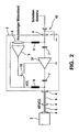
- FIG. 1 shows a vehicle rear window 1, the heating wires are used for Scheibenffrostung as an antenna.
- a Anlennenanpasscut 3 that is, an impedance converter, which is designed here as an active amplifier circuit 31.
- the DC supply signal for the active circuit 3 is used simultaneously as a diagnostic signal for the connectors 4 in the antenna signal path. It is guided via the RF cable 5 to the impedance converter 3. Here it is separated via the throttles 6 in the shunt branch and the capacitors 7 in the longitudinal branch and past the active circuit 31. At the disk-side terminal end of the active circuit 31, it is added back to the RF antenna signal.
- the diagnostic signal in the secondary path of the active circuit 31 via a particular high-impedance diagnostic resistor 8, for example, 10 k ohm out.
- the diagnosis of the correct or existing plug contact is detected on the one hand by a voltage drop across a diagnostic resistor 8, resulting in a steady current flow results. On the other hand, by an interruption of the power supply.
- the diagnostic method or the diagnostic device according to the invention is characterized in that the diagnostic signals are fed to the RF antenna port and thus no additional plug contacts are needed.
- a circuit breaker 10 for the active circuit 31 is activated via the voltage drop across the high-impedance diagnostic resistor 8 by the connected to the diagnostic resistor 8 evaluation unit 9. By this switching off of the active circuit 31 no or only a very small current flows. This is detected in the receiver 2, that is, the power consumption of the active circuit 31 is outside a predetermined window and it is signaled a fault in the receiver 2.
- the heating field is on one side to ground, so that the detection is easily possible via only one disk-side plug contact.
- the detection via a bridge 42 to ground in the disk connector 4 done.
- the monitored connectors are marked in all figures with a dark filled rectangle.
- the diagnostic resistor 8 in the secondary path of the active circuit 31 is not necessary because the diagnostic signal is returned after passing through the disk-side connector via the bridge 43 to the power supply terminal 32 of the active circuit 31.
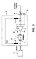
- the plug-in connections of the diversity stage 21 upstream of the matching stage 3 are also monitored.
- the diagnostic signal is also phantom-powered here via the RF cable 5 of the antenna signal path and is separated at the input of the diversity device 21, bypassed the active circuit of the diversity device 21 and added at the output of the RF signal again.
- FIG. 5 shows a diversity device 21 with an integrated (downstream) matching stage.
- the diagnostic signal is here separated at the input of the diversity device 21, passed to the / the active circuit / s the diversity device and the matching stage 3 over to the disk-side output of the matching stage and there added back to the RF signal.
- FIG. 6 shows an alternative to FIG. 5 with integrated diversity facility.
- the diagnostic resistor 8 provided with evaluation unit 9 and power supply breaker 10 as an alternative to returning the diagnostic signal via a bridge on the disk-side connector.
- FIG. 7 shows the forwarding of the diagnostic signal to the active circuit of the upstream diversity device and the evaluation of the voltage drop to accordingly FIG. 1 provided diagnostic resistor 8 in the matching circuit.
Claims (10)
- Procédé de diagnostic pour surveiller au moins une connexion enfichée vers une antenne, notamment une connexion enfichée dans le chemin du signal d'antenne vers une antenne de pare-brise de véhicule automobile, comprenant les étapes suivantes :- un signal de diagnostic est injecté en direction de l'antenne (1) par le biais du chemin du signal d'antenne,- le signal de diagnostic est acheminé à un circuit actif (31) prévu dans le chemin du signal d'antenne,- l'alimentation électrique du circuit actif (31) est influencée en fonction d'un défaut provoqué ou non au signal de diagnostic par l'au moins une connexion enfichée (4),- il est détecté si la consommation électrique du circuit actif (31) se trouve en-dehors d'un créneau prédéfini et un défaut est signalé le cas échéant.
- Procédé de diagnostic selon la revendication 1, caractérisé en ce que le signal de diagnostic utilisé est le signal d'alimentation en courant continu pour le circuit actif (31).
- Procédé de diagnostic selon la revendication 1 ou 2, caractérisé en ce que le signal de diagnostic passe par une résistance de diagnostic (8), en ce que la chute de tension aux bornes de la résistance de diagnostic (8) est surveillée et en ce que dans le cas d'un défaut au niveau de l'au moins une connexion enfichée (4), un interrupteur d'alimentation électrique (10) pour le circuit actif (31) est activé par le biais de la chute de tension aux bornes de la résistance de diagnostic (8).
- Procédé de diagnostic selon la revendication 1 ou 2, caractérisé en ce que le signal de diagnostic retourne vers le circuit actif (31), à savoir vers sa borne d'alimentation électrique (32), après être passé à travers la connexion enfichée (4) côté antenne.
- Procédé de diagnostic selon l'une des revendications 1 à 4, caractérisé en ce que le signal de diagnostic est acheminé à un dispositif à diversité (21) prévu dans le chemin du signal d'antenne et il est ensuite de nouveau injecté dans le chemin du signal d'antenne.
- Procédé de diagnostic selon l'une des revendications 1 à 5, caractérisé en ce que le signal de diagnostic est injecté en tant que signal fantôme par le biais du chemin du signal d'antenne ou de son câble HF (5).
- Dispositif de diagnostic pour surveiller au moins une connexion enfichée vers une antenne, notamment une connexion enfichée dans le chemin du signal d'antenne vers une antenne de pare-brise de véhicule automobile, ayant les caractéristiques suivantes :- des moyens pour générer un signal de diagnostic et pour l'injecter dans le chemin du signal d'antenne en direction de l'antenne (1),- des moyens pour acheminer le signal de diagnostic à un circuit actif (31) dans le chemin du signal d'antenne (31),- des moyens pour influencer l'alimentation électrique du circuit actif (31) en fonction d'un défaut provoqué ou non au signal de diagnostic par l'au moins une connexion enfichée (4),- des moyens pour détecter la consommation électrique du circuit actif (31) et pour signaler un défaut lorsque la consommation électrique se trouve en-dehors d'un créneau prédéfini.
- Dispositif de diagnostic selon la revendication 7, caractérisé en ce qu'il est prévu une résistance de diagnostic (8) dans la branche d'acheminement du circuit actif (31), en ce que la résistance de diagnostic (8) est reliée à une unité d'interprétation (9) au moyen de laquelle peut être actionné un interrupteur d'alimentation électrique (10) pour le circuit actif (31).
- Dispositif de diagnostic selon la revendication 7 ou 8, caractérisé en ce que des moyens sont prévus pour renvoyer le signal de diagnostic après qu'il soit passé à travers la connexion enfichée (4, 43) côté antenne vers une borne d'alimentation électrique (32) du circuit actif (31).
- Dispositif de diagnostic selon l'une des revendications 7 à 9, caractérisé en ce qu'une injection fantôme du signal de diagnostic, lequel est notamment le signal d'alimentation en courant continu pour le circuit actif (31), est prévue par le biais du chemin du signal d'antenne ou de son câble HF (5).
Applications Claiming Priority (2)
| Application Number | Priority Date | Filing Date | Title |
|---|---|---|---|
| DE10360209A DE10360209A1 (de) | 2003-12-20 | 2003-12-20 | Diagnoseverfahren zur Überwachung einer Steckverbindung |
| PCT/EP2004/052879 WO2005062063A1 (fr) | 2003-12-20 | 2004-11-09 | Procede de diagnostic pour le controle d'une connexion a fiches |
Publications (2)
| Publication Number | Publication Date |
|---|---|
| EP1725883A1 EP1725883A1 (fr) | 2006-11-29 |
| EP1725883B1 true EP1725883B1 (fr) | 2013-09-18 |
Family
ID=34706382
Family Applications (1)
| Application Number | Title | Priority Date | Filing Date |
|---|---|---|---|
| EP04804520.7A Expired - Fee Related EP1725883B1 (fr) | 2003-12-20 | 2004-11-09 | Procede de diagnostic pour le controle d'une connexion a fiches |
Country Status (6)
| Country | Link |
|---|---|
| US (1) | US7400152B2 (fr) |
| EP (1) | EP1725883B1 (fr) |
| JP (1) | JP4273120B2 (fr) |
| BR (1) | BRPI0407418A (fr) |
| DE (1) | DE10360209A1 (fr) |
| WO (1) | WO2005062063A1 (fr) |
Families Citing this family (11)
| Publication number | Priority date | Publication date | Assignee | Title |
|---|---|---|---|---|
| US6878206B2 (en) | 2001-07-16 | 2005-04-12 | Applied Materials, Inc. | Lid assembly for a processing system to facilitate sequential deposition techniques |
| DE102007055442A1 (de) * | 2007-11-20 | 2009-05-28 | Volkswagen Ag | Verfahren und Vorrichtung zur Diagnose von einer Antennenverbindung für ein Kraftfahrzeug |
| EP2771185B1 (fr) | 2011-10-28 | 2018-11-28 | Corning Incorporated | Articles en verre à réflectivité infrarouge et leurs procédés de fabrication |
| DE102012200710A1 (de) * | 2012-01-19 | 2013-07-25 | Bayerische Motoren Werke Aktiengesellschaft | Empfangseinrichtung, insbesondere für ein Kraftfahrzeug |
| EP2658133A1 (fr) | 2012-04-26 | 2013-10-30 | Harman Becker Automotive Systems GmbH | Système d'antennes multiples |
| EP2658134A1 (fr) | 2012-04-26 | 2013-10-30 | Harman Becker Automotive Systems GmbH | Système d'antennes multiples |
| FI124557B (en) * | 2012-05-03 | 2014-10-15 | Tellabs Oy | Equipment with one or more plug-in units |
| EP2690793B1 (fr) * | 2012-07-27 | 2015-07-01 | Harman Becker Automotive Systems GmbH | Système d'antennes multiples |
| DE102015102352A1 (de) * | 2015-02-19 | 2016-08-25 | Dr. Ing. H.C. F. Porsche Aktiengesellschaft | Verfahren und Vorrichtung zum Überwachen eines Ruhezustandes bei einem Kraftfahrzeug |
| CN107531562B (zh) | 2015-04-30 | 2021-05-28 | 康宁股份有限公司 | 具有离散的金属银层的导电制品及其制造方法 |
| FR3059437B1 (fr) * | 2016-11-30 | 2019-01-25 | Continental Automotive France | Procede de diagnostic d'un lien de communication dans un vehicule automobile |
Family Cites Families (7)
| Publication number | Priority date | Publication date | Assignee | Title |
|---|---|---|---|---|
| KR960009446B1 (en) | 1993-12-23 | 1996-07-19 | Hyundai Electronics Ind | A diversity device of gps antenna |
| JPH08172377A (ja) * | 1994-12-19 | 1996-07-02 | Mitsubishi Electric Corp | アンテナ切換回路 |
| JP4219436B2 (ja) * | 1998-02-17 | 2009-02-04 | 富士通株式会社 | チューナ装置 |
| DE19923729A1 (de) * | 1999-05-22 | 2000-11-23 | Nokia Mobile Phones Ltd | Schaltungsanordnung zum Prüfen der Funktionsbereitschaft mindestens einer Antenne |
| DE10033336A1 (de) * | 1999-08-11 | 2001-04-12 | Heinz Lindenmeier | Diversityantenne für eine Diversityantennenanlage in einem Fahrzeug |
| JP2002319907A (ja) | 2001-04-20 | 2002-10-31 | Fujitsu General Ltd | 衛星放送アンテナの故障検出装置 |
| US6853197B1 (en) | 2001-12-03 | 2005-02-08 | Atheros Communications, Inc. | Method and apparatus for insuring integrity of a connectorized antenna |
-
2003
- 2003-12-20 DE DE10360209A patent/DE10360209A1/de not_active Withdrawn
-
2004
- 2004-11-09 JP JP2005518537A patent/JP4273120B2/ja not_active Expired - Fee Related
- 2004-11-09 BR BR0407418-1A patent/BRPI0407418A/pt not_active IP Right Cessation
- 2004-11-09 EP EP04804520.7A patent/EP1725883B1/fr not_active Expired - Fee Related
- 2004-11-09 US US10/581,159 patent/US7400152B2/en active Active
- 2004-11-09 WO PCT/EP2004/052879 patent/WO2005062063A1/fr active Application Filing
Also Published As
| Publication number | Publication date |
|---|---|
| JP4273120B2 (ja) | 2009-06-03 |
| EP1725883A1 (fr) | 2006-11-29 |
| DE10360209A1 (de) | 2005-07-28 |
| JP2006519361A (ja) | 2006-08-24 |
| BRPI0407418A (pt) | 2006-01-10 |
| WO2005062063A1 (fr) | 2005-07-07 |
| US20070152675A1 (en) | 2007-07-05 |
| US7400152B2 (en) | 2008-07-15 |
Similar Documents
| Publication | Publication Date | Title |
|---|---|---|
| DE19923729A1 (de) | Schaltungsanordnung zum Prüfen der Funktionsbereitschaft mindestens einer Antenne | |
| DE102008035634B4 (de) | Schaltleiste für die Erfassung von Hindernissen und Vorrichtung zum Erfassen von Hindernissen | |
| EP1725883B1 (fr) | Procede de diagnostic pour le controle d'une connexion a fiches | |
| EP0714178B1 (fr) | Système de diversité multi-antennes à balayage des signaux pour véhicules | |
| DE10305741A1 (de) | Verfahren und Anordnung zum Prüfen mindestens einer Antenne | |
| DE102007020882B4 (de) | Einrichtung zur Überprüfung der Befestigung einer Leiterbahnplatte an einem Träger | |
| DE102013014824A1 (de) | Kapazitiver Sensor für ein Fahrzeug | |
| DE102005016127A1 (de) | Sensorsystem | |
| DE4325663A1 (de) | Stromversorgungsschalter-Relaisschaltung | |
| DE102020214614B3 (de) | Schaltungsanordnung zur Spannungsprüfung und Teilentladungserfassung | |
| EP2553192B1 (fr) | Serrure de porte de véhicule à moteur | |
| DE10211341A1 (de) | Diversity-Antennensystem für bewegte Fahrzeuge | |
| EP1198716B1 (fr) | Circuit et procede pour le controle d'un systeme a diversite de commutation | |
| DE102014000345B4 (de) | Empfangsschaltung für Stromleitungsträgerkommunikation | |
| DE10228851B4 (de) | Richtkoppler | |
| EP4043893A1 (fr) | Agencement de circuit destiné au contrôle de la tension et à la détection de la décharge partielle | |
| DE102007055442A1 (de) | Verfahren und Vorrichtung zur Diagnose von einer Antennenverbindung für ein Kraftfahrzeug | |
| EP1829166B1 (fr) | Système de diagnostic pour la surveillance d'une connexion par fiches | |
| DE102006060114A1 (de) | Verfahren und Vorrichtung zur Überprüfung von Kraftfahrzeug-Bordnetz-Komponenten bei der Montage von Kraftfahrzeugen | |
| DE102018126787A1 (de) | Ladestation für Elektrofahrzeuge mit mindestens zwei Ladeanschlüssen und einer wahlweise auf diese schaltbare Leistungselektronikeinheit | |
| WO2005026971A1 (fr) | Circuit servant d'interface entre une carte sim et un modem gsm | |
| EP1536563B1 (fr) | Circuit de commutation de charge et procédé diagnostique associé | |
| DE10200782C1 (de) | Schaltungsanordnung zur Prüfung einer ein- oder mehrkanaligen Steckverbindungsleitung zwischen einem Radio und einem Audioverstärker | |
| WO2017005858A1 (fr) | Détecteur de courant de fuite pour dispositif de protection contre un courant de fuite destiné à la surveillance d'un consommateur électrique pour un véhicule | |
| WO1998013976A1 (fr) | Systeme de couplage de ligne de repeteur |
Legal Events
| Date | Code | Title | Description |
|---|---|---|---|
| PUAI | Public reference made under article 153(3) epc to a published international application that has entered the european phase |
Free format text: ORIGINAL CODE: 0009012 |
|
| 17P | Request for examination filed |
Effective date: 20060720 |
|
| AK | Designated contracting states |
Kind code of ref document: A1 Designated state(s): DE FR IT |
|
| DAX | Request for extension of the european patent (deleted) | ||
| RBV | Designated contracting states (corrected) |
Designated state(s): DE FR IT |
|
| GRAP | Despatch of communication of intention to grant a patent |
Free format text: ORIGINAL CODE: EPIDOSNIGR1 |
|
| INTG | Intention to grant announced |
Effective date: 20130618 |
|
| GRAS | Grant fee paid |
Free format text: ORIGINAL CODE: EPIDOSNIGR3 |
|
| GRAA | (expected) grant |
Free format text: ORIGINAL CODE: 0009210 |
|
| AK | Designated contracting states |
Kind code of ref document: B1 Designated state(s): DE FR IT |
|
| REG | Reference to a national code |
Ref country code: DE Ref legal event code: R096 Ref document number: 502004014362 Country of ref document: DE Effective date: 20131114 |
|
| REG | Reference to a national code |
Ref country code: DE Ref legal event code: R097 Ref document number: 502004014362 Country of ref document: DE |
|
| PLBE | No opposition filed within time limit |
Free format text: ORIGINAL CODE: 0009261 |
|
| STAA | Information on the status of an ep patent application or granted ep patent |
Free format text: STATUS: NO OPPOSITION FILED WITHIN TIME LIMIT |
|
| 26N | No opposition filed |
Effective date: 20140619 |
|
| REG | Reference to a national code |
Ref country code: DE Ref legal event code: R097 Ref document number: 502004014362 Country of ref document: DE Effective date: 20140619 |
|
| PGFP | Annual fee paid to national office [announced via postgrant information from national office to epo] |
Ref country code: FR Payment date: 20141118 Year of fee payment: 11 |
|
| PGFP | Annual fee paid to national office [announced via postgrant information from national office to epo] |
Ref country code: IT Payment date: 20141125 Year of fee payment: 11 |
|
| PG25 | Lapsed in a contracting state [announced via postgrant information from national office to epo] |
Ref country code: IT Free format text: LAPSE BECAUSE OF NON-PAYMENT OF DUE FEES Effective date: 20151109 |
|
| REG | Reference to a national code |
Ref country code: FR Ref legal event code: ST Effective date: 20160729 |
|
| PG25 | Lapsed in a contracting state [announced via postgrant information from national office to epo] |
Ref country code: FR Free format text: LAPSE BECAUSE OF NON-PAYMENT OF DUE FEES Effective date: 20151130 |
|
| REG | Reference to a national code |
Ref country code: DE Ref legal event code: R084 Ref document number: 502004014362 Country of ref document: DE |
|
| REG | Reference to a national code |
Ref country code: DE Ref legal event code: R079 Ref document number: 502004014362 Country of ref document: DE Free format text: PREVIOUS MAIN CLASS: G01R0031040000 Ipc: G01R0031660000 |
|
| PGFP | Annual fee paid to national office [announced via postgrant information from national office to epo] |
Ref country code: DE Payment date: 20200124 Year of fee payment: 16 |
|
| REG | Reference to a national code |
Ref country code: DE Ref legal event code: R119 Ref document number: 502004014362 Country of ref document: DE |
|
| PG25 | Lapsed in a contracting state [announced via postgrant information from national office to epo] |
Ref country code: DE Free format text: LAPSE BECAUSE OF NON-PAYMENT OF DUE FEES Effective date: 20210601 |