EP1725883B1 - Diagnostic method for monitoring a plug-in connection - Google Patents
Diagnostic method for monitoring a plug-in connection Download PDFInfo
- Publication number
- EP1725883B1 EP1725883B1 EP04804520.7A EP04804520A EP1725883B1 EP 1725883 B1 EP1725883 B1 EP 1725883B1 EP 04804520 A EP04804520 A EP 04804520A EP 1725883 B1 EP1725883 B1 EP 1725883B1
- Authority
- EP
- European Patent Office
- Prior art keywords
- diagnostic
- antenna
- signal
- active circuit
- connection
- Prior art date
- Legal status (The legal status is an assumption and is not a legal conclusion. Google has not performed a legal analysis and makes no representation as to the accuracy of the status listed.)
- Expired - Fee Related
Links
Images


Classifications
-
- G—PHYSICS
- G01—MEASURING; TESTING
- G01R—MEASURING ELECTRIC VARIABLES; MEASURING MAGNETIC VARIABLES
- G01R31/00—Arrangements for testing electric properties; Arrangements for locating electric faults; Arrangements for electrical testing characterised by what is being tested not provided for elsewhere
- G01R31/50—Testing of electric apparatus, lines, cables or components for short-circuits, continuity, leakage current or incorrect line connections
- G01R31/66—Testing of connections, e.g. of plugs or non-disconnectable joints
- G01R31/68—Testing of releasable connections, e.g. of terminals mounted on a printed circuit board
Definitions
- the invention relates to a diagnostic method for monitoring at least one plug connection to an antenna, in particular a plug connection in the antenna signal path to a motor vehicle window pane antenna.
- the receiver e.g. Radio or TV box to set a current window for a normal operating range of an active circuit in the antenna signal path. If the power consumption is not in the specified current window, a fault is signaled.
- the method according to the invention makes it possible to detect a lack of contact with the disk in a simple manner.
- the invention offers the possibility to monitor all connectors in different antenna structures, even those of an optionally provided diversity device.
- the method according to the invention is characterized in that the diagnostic signal / signals are fed to the RF antenna port of the receiver to the antenna, that is, into the RF cable to the antenna. Thus, no additional plug contacts are necessary.
- the heating field is always one-sided to ground, so that the detection is simply possible here via just one plug-in contact.
- detection can take place via a bridge in the disk connector.
- FIG. 1 shows a vehicle rear window 1, the heating wires are used for Scheibenffrostung as an antenna.
- a Anlennenanpasscut 3 that is, an impedance converter, which is designed here as an active amplifier circuit 31.
- the DC supply signal for the active circuit 3 is used simultaneously as a diagnostic signal for the connectors 4 in the antenna signal path. It is guided via the RF cable 5 to the impedance converter 3. Here it is separated via the throttles 6 in the shunt branch and the capacitors 7 in the longitudinal branch and past the active circuit 31. At the disk-side terminal end of the active circuit 31, it is added back to the RF antenna signal.
- the diagnostic signal in the secondary path of the active circuit 31 via a particular high-impedance diagnostic resistor 8, for example, 10 k ohm out.
- the diagnosis of the correct or existing plug contact is detected on the one hand by a voltage drop across a diagnostic resistor 8, resulting in a steady current flow results. On the other hand, by an interruption of the power supply.
- the diagnostic method or the diagnostic device according to the invention is characterized in that the diagnostic signals are fed to the RF antenna port and thus no additional plug contacts are needed.
- a circuit breaker 10 for the active circuit 31 is activated via the voltage drop across the high-impedance diagnostic resistor 8 by the connected to the diagnostic resistor 8 evaluation unit 9. By this switching off of the active circuit 31 no or only a very small current flows. This is detected in the receiver 2, that is, the power consumption of the active circuit 31 is outside a predetermined window and it is signaled a fault in the receiver 2.
- the heating field is on one side to ground, so that the detection is easily possible via only one disk-side plug contact.
- the detection via a bridge 42 to ground in the disk connector 4 done.
- the monitored connectors are marked in all figures with a dark filled rectangle.
- the diagnostic resistor 8 in the secondary path of the active circuit 31 is not necessary because the diagnostic signal is returned after passing through the disk-side connector via the bridge 43 to the power supply terminal 32 of the active circuit 31.
- the plug-in connections of the diversity stage 21 upstream of the matching stage 3 are also monitored.
- the diagnostic signal is also phantom-powered here via the RF cable 5 of the antenna signal path and is separated at the input of the diversity device 21, bypassed the active circuit of the diversity device 21 and added at the output of the RF signal again.
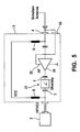
- FIG. 5 shows a diversity device 21 with an integrated (downstream) matching stage.
- the diagnostic signal is here separated at the input of the diversity device 21, passed to the / the active circuit / s the diversity device and the matching stage 3 over to the disk-side output of the matching stage and there added back to the RF signal.
- FIG. 6 shows an alternative to FIG. 5 with integrated diversity facility.
- the diagnostic resistor 8 provided with evaluation unit 9 and power supply breaker 10 as an alternative to returning the diagnostic signal via a bridge on the disk-side connector.
- FIG. 7 shows the forwarding of the diagnostic signal to the active circuit of the upstream diversity device and the evaluation of the voltage drop to accordingly FIG. 1 provided diagnostic resistor 8 in the matching circuit.
Description
Die Erfindung betrifft ein Diagnoseverfahren zur Überwachung mindestens einer Steckverbindung zu einer Antenne insbesondere einer Steckverbindung im Antennensignalpfad zu einer Kraftfahrzeug-Scheibenantenne.The invention relates to a diagnostic method for monitoring at least one plug connection to an antenna, in particular a plug connection in the antenna signal path to a motor vehicle window pane antenna.
Zur Diagnose von Steckverbindern bzw. Steckverbindungen ist es bekannt im Empfänger, z.B. Radio oder TV-Box, ein Stromfenster für einen normalen Betriebsbereich einer aktiven Schaltung im Antennensignalpfad festzulegen. Wenn der Stromverbrauch nicht im vorgegebenen Stromfenster liegt, wird eine Störung signalisiert.For the diagnosis of connectors, it is known in the receiver, e.g. Radio or TV box to set a current window for a normal operating range of an active circuit in the antenna signal path. If the power consumption is not in the specified current window, a fault is signaled.
In Dokument
Mit den Maßnahmen des Anspruchs 1, das heißt mit den Schritten:
- ein Diagnosesignal wird über den Antennensignalpfad in Richtung Antenne gespeist,
- an einer im Antennensignalpfad vorgesehenen aktiven Schaltung wird das Diagnosesignal vorbeigeführt,
- in Abhängigkeit davon, ob das Diagnosesignal durch die mindestens eine Steckverbindung eine Störung erfährt wird die Stromversorgung der aktiven Schaltung beeinflusst,
- es wird detektiert, ob der Stromverbrauch der aktiven Schaltung außerhalb eines vorgegebenen Fensters liegt und gegebenenfalls eine Störung signalisiert, können im Gegensatz zu herkömmlichen Lösungen mehr Steckverbindungen diagnostiziert werden, insbesondere die Steckverbindung/die Steckverbinder zur Kfz-Scheibenantenne. Bei herkömmlichen Lösungen wird nur eine Diagnose für den Steckverbinder vom Empfänger zum Impedanzwandler, das heißt zur aktiven Schaltung für die Antennenanpassung, durchgeführt. Eine Diagnose der Steckverbindung zur Scheibenantenne erfolgt nicht oder nur über eine Schleife mit zwei separaten Kontakten.
- a diagnostic signal is fed via the antenna signal path in the direction of the antenna,
- at an active circuit provided in the antenna signal path, the diagnostic signal is passed,
- Depending on whether the diagnostic signal is disturbed by the at least one plug connection, the power supply of the active circuit is influenced,
- It is detected whether the power consumption of the active circuit is outside of a predetermined window and possibly signals a fault, in contrast to conventional solutions more connectors are diagnosed, in particular the connector / the connector to the car window antenna. In conventional solutions, only one diagnosis is made for the connector from the receiver to the impedance transformer, that is, the antenna matching active circuit. A diagnosis of the connector to the glass antenna is not or only via a loop with two separate contacts.
Bei komplexen Diversity-Systemen ist mit dem Verfahren nach der Erfindung auf einfache Weise ein fehlender Scheibenkontakt festzustellen. Die Erfindung bietet die Möglichkeit bei unterschiedlichen Antennenstrukturen alle Steckverbinder zu überwachen, auch jene einer optional vorgesehenen Diversity-Einrichtung.In complex diversity systems, the method according to the invention makes it possible to detect a lack of contact with the disk in a simple manner. The invention offers the possibility to monitor all connectors in different antenna structures, even those of an optionally provided diversity device.
Das Verfahren nach der Erfindung zeichnet sich dadurch aus, dass das Diagnosesignal/die Diagnosesignale auf den HF-Antennenanschluss des Empfängers zur Antenne eingespeist werden, das heißt in das HF-Kabel zur Antenne. Somit sind keine zusätzlichen Steckerkontakte notwendig.The method according to the invention is characterized in that the diagnostic signal / signals are fed to the RF antenna port of the receiver to the antenna, that is, into the RF cable to the antenna. Thus, no additional plug contacts are necessary.
Bei Heckscheibenantennen liegt das Heizfeld immer einseitig auf Masse, so dass hier die Detektion einfach über nur einen Steckkontakt möglich ist.In the case of rear window antennas, the heating field is always one-sided to ground, so that the detection is simply possible here via just one plug-in contact.
Bei separaten Antennenstrukturen kann eine Detektion über eine Brücke im Scheibenanschlussstecker erfolgen.In the case of separate antenna structures, detection can take place via a bridge in the disk connector.
Anhand der Zeichnungen werden Ausfübrungsbeispiele der Erfindung erläutert. Es zeigen
-
Figur 1 ein erstes Ausführungsbeispiel mit einseitig geerdeter Antennenstruktur, -
Figur 2 -
Figur 3 -
Figur 4 -
Figur 5 -
Figur 6 -
Figur 7
-
FIG. 1 A first embodiment with a one-sided grounded antenna structure, -
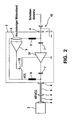
FIG. 2 an alternative embodiment for any antenna structure, -
FIG. 3 a feedback of the diagnostic signal to the power supply of an active circuit, -
FIG. 4 a monitoring of a diversity facility, -
FIG. 5 an alternative embodiment for monitoring the diversity device, -
FIG. 6 an alternative to monitoring the diversity device and evaluation via a diagnostic resistor, -
FIG. 7 another alternative to monitoring a diversity facility.
Die Diagnose der richtigen oder vorhandenen Steckerkontaktierung wird einerseits durch einen Spannungsabfall an einem Diagnosewiderstand 8 detektiert, woraus ein stetiger Stromfluss resultiert. Andererseits durch eine Unterbrechung der Spannungsversorgung. Das Diagnoseverfahren bzw. die Diagnoseeinrichtung nach der Erfindung zeichnet sich dadurch aus, dass die Diagnosesignale auf den HF-Antennenanschluss eingespeist werden und somit keine zusätzlichen Steckerkontakte benötigt werden.The diagnosis of the correct or existing plug contact is detected on the one hand by a voltage drop across a
Wenn eine Verbindung nicht gesteckt ist oder der Steckkontakt nicht fehlerfrei ist, wird über den Spannungsabfall an dem hochohmigen Diagnosewiderstand 8 durch die an dem Diagnosewiderstand 8 angeschlossene Auswerteeinheit 9 ein Stromunterbrecher 10 für die aktive Schaltung 31 aktiviert. Durch dieses Abschalten der aktiven Schaltung 31 fließt kein oder nur ein sehr geringer Strom. Dies wird im Empfänger 2 detektiert, das heißt der Stromverbrauch der aktiven Schaltung 31 liegt außerhalb eines vorgegebenen Fensters und es wird eine Störung im Empfänger 2 signalisiert. Bei der in
Beim Ausführungsbeispiel gemäß
Bei Ausführungsbeispiel gemäß
Claims (10)
- Diagnostic method for monitoring at least one plug-in connection to an antenna, in particular a plug-in connection in the antenna signal path to a motor vehicle windowpane antenna, having the following steps:- a diagnostic signal is fed in in the direction of the antenna (1) via the antenna signal path,- the diagnostic signal is guided past an active circuit (31) provided in the antenna signal path,- the power supply for the active circuit (31) is influenced depending on whether the diagnostic signal experiences interference as a result of the at least one plug-in connection (4),- it is detected whether the power consumption of the active circuit (31) is outside a predefined window and possibly signals interference.
- Diagnostic method according to Claim 1, characterized in that the direct current feed signal for the active circuit (31) is used as the diagnostic signal.
- Diagnostic method according to Claim 1 or 2, characterized in that the diagnostic signal is guided via a diagnostic resistor (8), in that the voltage drop across the diagnostic resistor (8) is monitored, and in that a power supply interrupter (10) for the active circuit (31) is activated in the event of interference in the at least one plug-in connection (4) via the voltage drop across the diagnostic resistor (8).
- Diagnostic method according to Claim 1 or 2, characterized in that, after passing through the plug-in connection (4) on the antenna side, the diagnostic signal is fed back to the active circuit (31), to be precise to the power supply connection (32) of the latter.
- Diagnostic method according to one of Claims 1 to 4, characterized in that the diagnostic signal is guided past a diversity device (21) provided in the antenna signal path and is then fed into the antenna signal path again.
- Diagnostic method according to one of Claims 1 to 5, characterized in that the diagnostic signal is phantom-fed via the antenna signal path or its RF cable (5).
- Diagnostic device for monitoring at least one plug-in connection to an antenna, in particular a plug-in connection in the antenna signal path to a motor vehicle windowpane antenna, having the following features:- means for generating a diagnostic signal and for feeding said signal into the antenna signal path in the direction of the antenna (1),- means for guiding the diagnostic signal past an active circuit (31) in the antenna signal path (31),- means for influencing the power supply for the active circuit (31) on the basis of whether the diagnostic signal experiences interference as a result of the at least one plug-in connection (4),- means for detecting the power consumption of the active circuit (31) and for signalling interference if the power consumption is outside a predefined window.
- Diagnostic device according to Claim 7, characterized in that a diagnostic resistor (8) is provided in the guiding-past branch of the active circuit (31), in that the diagnostic resistor (8) is connected to an evaluation unit (9) which can be used to actuate a power supply interrupter (19) for the active circuit (31).
- Diagnostic device according to Claim 7 or 8, characterized in that means are provided for feeding the diagnostic signal back to a power supply connection (32) of the active circuit (31) after passing through the plug-in connection (4, 43) on the antenna side.
- Diagnostic device according to one of Claims 7 to 9, characterized in that phantom feeding of the diagnostic signal, which is the direct current feed signal for the active circuit (31) in particular, is provided via the antenna signal path or its RF cable (5).
Applications Claiming Priority (2)
| Application Number | Priority Date | Filing Date | Title |
|---|---|---|---|
| DE10360209A DE10360209A1 (en) | 2003-12-20 | 2003-12-20 | Diagnostic method for monitoring a plug connection |
| PCT/EP2004/052879 WO2005062063A1 (en) | 2003-12-20 | 2004-11-09 | Diagnostic method for monitoring a plug-in connection |
Publications (2)
| Publication Number | Publication Date |
|---|---|
| EP1725883A1 EP1725883A1 (en) | 2006-11-29 |
| EP1725883B1 true EP1725883B1 (en) | 2013-09-18 |
Family
ID=34706382
Family Applications (1)
| Application Number | Title | Priority Date | Filing Date |
|---|---|---|---|
| EP04804520.7A Expired - Fee Related EP1725883B1 (en) | 2003-12-20 | 2004-11-09 | Diagnostic method for monitoring a plug-in connection |
Country Status (6)
| Country | Link |
|---|---|
| US (1) | US7400152B2 (en) |
| EP (1) | EP1725883B1 (en) |
| JP (1) | JP4273120B2 (en) |
| BR (1) | BRPI0407418A (en) |
| DE (1) | DE10360209A1 (en) |
| WO (1) | WO2005062063A1 (en) |
Families Citing this family (11)
| Publication number | Priority date | Publication date | Assignee | Title |
|---|---|---|---|---|
| US6878206B2 (en) | 2001-07-16 | 2005-04-12 | Applied Materials, Inc. | Lid assembly for a processing system to facilitate sequential deposition techniques |
| DE102007055442A1 (en) * | 2007-11-20 | 2009-05-28 | Volkswagen Ag | Antenna connection diagnosis method for motor vehicle, involves supplying current for predetermined time interval to test connection between receiver e.g. radio/navigation device, and antenna terminal |
| CN103930268B (en) | 2011-10-28 | 2016-08-31 | 康宁股份有限公司 | There is glass and the manufacture method thereof of infrared reflective |
| DE102012200710A1 (en) * | 2012-01-19 | 2013-07-25 | Bayerische Motoren Werke Aktiengesellschaft | Receiver for motor vehicle, has common central antenna unit comprising diagnostic unit for performing diagnosis of antenna system in response to variable in amount of operating voltage of antenna system |
| EP2658133A1 (en) | 2012-04-26 | 2013-10-30 | Harman Becker Automotive Systems GmbH | Multi-antenna system |
| EP2658134A1 (en) | 2012-04-26 | 2013-10-30 | Harman Becker Automotive Systems GmbH | Multi-antenna system |
| FI124557B (en) * | 2012-05-03 | 2014-10-15 | Tellabs Oy | Equipment with one or more insert units |
| EP2690793B1 (en) | 2012-07-27 | 2015-07-01 | Harman Becker Automotive Systems GmbH | Multiple-antenna system |
| DE102015102352A1 (en) * | 2015-02-19 | 2016-08-25 | Dr. Ing. H.C. F. Porsche Aktiengesellschaft | Method and device for monitoring a resting state in a motor vehicle |
| WO2016176096A1 (en) | 2015-04-30 | 2016-11-03 | Corning Incorporated | Electrically conductive articles with discrete metallic silver layers and methods for making same |
| FR3059437B1 (en) * | 2016-11-30 | 2019-01-25 | Continental Automotive France | METHOD FOR DIAGNOSING A COMMUNICATION LINK IN A MOTOR VEHICLE |
Family Cites Families (7)
| Publication number | Priority date | Publication date | Assignee | Title |
|---|---|---|---|---|
| KR960009446B1 (en) | 1993-12-23 | 1996-07-19 | Hyundai Electronics Ind | A diversity device of gps antenna |
| JPH08172377A (en) * | 1994-12-19 | 1996-07-02 | Mitsubishi Electric Corp | Antenna switching circuit |
| JP4219436B2 (en) * | 1998-02-17 | 2009-02-04 | 富士通株式会社 | Tuner device |
| DE19923729A1 (en) * | 1999-05-22 | 2000-11-23 | Nokia Mobile Phones Ltd | Circuit arrangement for checking the operational readiness of at least one antenna |
| DE10033336A1 (en) * | 1999-08-11 | 2001-04-12 | Heinz Lindenmeier | Diversity antenna for diversity system in vehicle has edge conductor on side of conducting surface with minimum length of about tenth of wavelength, forming low impedance coupling line |
| JP2002319907A (en) | 2001-04-20 | 2002-10-31 | Fujitsu General Ltd | Fault detector for satellite broadcasting antenna |
| US6853197B1 (en) | 2001-12-03 | 2005-02-08 | Atheros Communications, Inc. | Method and apparatus for insuring integrity of a connectorized antenna |
-
2003
- 2003-12-20 DE DE10360209A patent/DE10360209A1/en not_active Withdrawn
-
2004
- 2004-11-09 US US10/581,159 patent/US7400152B2/en active Active
- 2004-11-09 BR BR0407418-1A patent/BRPI0407418A/en not_active IP Right Cessation
- 2004-11-09 JP JP2005518537A patent/JP4273120B2/en not_active Expired - Fee Related
- 2004-11-09 WO PCT/EP2004/052879 patent/WO2005062063A1/en active Application Filing
- 2004-11-09 EP EP04804520.7A patent/EP1725883B1/en not_active Expired - Fee Related
Also Published As
| Publication number | Publication date |
|---|---|
| JP2006519361A (en) | 2006-08-24 |
| US7400152B2 (en) | 2008-07-15 |
| DE10360209A1 (en) | 2005-07-28 |
| US20070152675A1 (en) | 2007-07-05 |
| EP1725883A1 (en) | 2006-11-29 |
| BRPI0407418A (en) | 2006-01-10 |
| WO2005062063A1 (en) | 2005-07-07 |
| JP4273120B2 (en) | 2009-06-03 |
Similar Documents
| Publication | Publication Date | Title |
|---|---|---|
| DE19923729A1 (en) | Circuit arrangement for checking the operational readiness of at least one antenna | |
| DE102008035634B4 (en) | Safety edge for detection of obstacles and device for detecting obstacles | |
| EP1725883B1 (en) | Diagnostic method for monitoring a plug-in connection | |
| EP0714178B1 (en) | Multi-antenna scanning diversity-system for vehicles | |
| DE10305741A1 (en) | Antenna signal sampling method provides instantaneous transmission coefficient from noise signals reaching sampling module directly and via antenna | |
| DE102011115309A1 (en) | Radar circuit, radar system and method for testing a connection between a radar circuit and a radar antenna in a vehicle | |
| DE102013014824A1 (en) | Capacitive sensor for a vehicle | |
| DE102005016127A1 (en) | sensor system | |
| DE4325663A1 (en) | Power switch relay circuit | |
| DE102020214614B3 (en) | Circuit arrangement for voltage testing and partial discharge detection | |
| EP1198716B1 (en) | Circuit arrangement and method for verifying a switching diversity system | |
| DE102014000345B4 (en) | Receiving circuit for power line carrier communication | |
| DE10228851B4 (en) | directional coupler | |
| DE202010004424U1 (en) | Motor vehicle door lock | |
| EP0736419A2 (en) | Device for the operation of at least one vehicle-mounted apparatus | |
| DE102021201465A1 (en) | Circuit arrangement for voltage testing and partial discharge detection | |
| DE102007055442A1 (en) | Antenna connection diagnosis method for motor vehicle, involves supplying current for predetermined time interval to test connection between receiver e.g. radio/navigation device, and antenna terminal | |
| EP1829166B1 (en) | Diagnostic system for monitoring a plug-in connection | |
| DE102006060114A1 (en) | Electric on-board supply system's component testing method, involves scanning value of supply current detected by current measurement using measuring resistor in central current line that is conveyed from one station to another | |
| DE102018126787A1 (en) | Charging station for electric vehicles with at least two charging connections and an optionally switchable power electronics unit | |
| DE112018003312T5 (en) | Capacitive sensor arrangement | |
| WO2005026971A1 (en) | Circuit arrangement that functions as an interface between a sim card and gsm modem | |
| EP1536563B1 (en) | Load switching circuit and diagnostic therefor | |
| DE10200782C1 (en) | Testing circuit for plug-in cable connection between radio and audio amplifier uses evaluation of DC voltage received at radio end of cable connection from virtual earth point at amplifier end | |
| EP3320591A1 (en) | Fault current sensor for a fault current protection device for monitoring an electrical consumer for a vehicle |
Legal Events
| Date | Code | Title | Description |
|---|---|---|---|
| PUAI | Public reference made under article 153(3) epc to a published international application that has entered the european phase |
Free format text: ORIGINAL CODE: 0009012 |
|
| 17P | Request for examination filed |
Effective date: 20060720 |
|
| AK | Designated contracting states |
Kind code of ref document: A1 Designated state(s): DE FR IT |
|
| DAX | Request for extension of the european patent (deleted) | ||
| RBV | Designated contracting states (corrected) |
Designated state(s): DE FR IT |
|
| GRAP | Despatch of communication of intention to grant a patent |
Free format text: ORIGINAL CODE: EPIDOSNIGR1 |
|
| INTG | Intention to grant announced |
Effective date: 20130618 |
|
| GRAS | Grant fee paid |
Free format text: ORIGINAL CODE: EPIDOSNIGR3 |
|
| GRAA | (expected) grant |
Free format text: ORIGINAL CODE: 0009210 |
|
| AK | Designated contracting states |
Kind code of ref document: B1 Designated state(s): DE FR IT |
|
| REG | Reference to a national code |
Ref country code: DE Ref legal event code: R096 Ref document number: 502004014362 Country of ref document: DE Effective date: 20131114 |
|
| REG | Reference to a national code |
Ref country code: DE Ref legal event code: R097 Ref document number: 502004014362 Country of ref document: DE |
|
| PLBE | No opposition filed within time limit |
Free format text: ORIGINAL CODE: 0009261 |
|
| STAA | Information on the status of an ep patent application or granted ep patent |
Free format text: STATUS: NO OPPOSITION FILED WITHIN TIME LIMIT |
|
| 26N | No opposition filed |
Effective date: 20140619 |
|
| REG | Reference to a national code |
Ref country code: DE Ref legal event code: R097 Ref document number: 502004014362 Country of ref document: DE Effective date: 20140619 |
|
| PGFP | Annual fee paid to national office [announced via postgrant information from national office to epo] |
Ref country code: FR Payment date: 20141118 Year of fee payment: 11 |
|
| PGFP | Annual fee paid to national office [announced via postgrant information from national office to epo] |
Ref country code: IT Payment date: 20141125 Year of fee payment: 11 |
|
| PG25 | Lapsed in a contracting state [announced via postgrant information from national office to epo] |
Ref country code: IT Free format text: LAPSE BECAUSE OF NON-PAYMENT OF DUE FEES Effective date: 20151109 |
|
| REG | Reference to a national code |
Ref country code: FR Ref legal event code: ST Effective date: 20160729 |
|
| PG25 | Lapsed in a contracting state [announced via postgrant information from national office to epo] |
Ref country code: FR Free format text: LAPSE BECAUSE OF NON-PAYMENT OF DUE FEES Effective date: 20151130 |
|
| REG | Reference to a national code |
Ref country code: DE Ref legal event code: R084 Ref document number: 502004014362 Country of ref document: DE |
|
| REG | Reference to a national code |
Ref country code: DE Ref legal event code: R079 Ref document number: 502004014362 Country of ref document: DE Free format text: PREVIOUS MAIN CLASS: G01R0031040000 Ipc: G01R0031660000 |
|
| PGFP | Annual fee paid to national office [announced via postgrant information from national office to epo] |
Ref country code: DE Payment date: 20200124 Year of fee payment: 16 |
|
| REG | Reference to a national code |
Ref country code: DE Ref legal event code: R119 Ref document number: 502004014362 Country of ref document: DE |
|
| PG25 | Lapsed in a contracting state [announced via postgrant information from national office to epo] |
Ref country code: DE Free format text: LAPSE BECAUSE OF NON-PAYMENT OF DUE FEES Effective date: 20210601 |