EP1722453A2 - Flush mounted box - Google Patents
Flush mounted box Download PDFInfo
- Publication number
- EP1722453A2 EP1722453A2 EP06290668A EP06290668A EP1722453A2 EP 1722453 A2 EP1722453 A2 EP 1722453A2 EP 06290668 A EP06290668 A EP 06290668A EP 06290668 A EP06290668 A EP 06290668A EP 1722453 A2 EP1722453 A2 EP 1722453A2
- Authority
- EP
- European Patent Office
- Prior art keywords
- tab
- box
- lugs
- screw
- lug
- Prior art date
- Legal status (The legal status is an assumption and is not a legal conclusion. Google has not performed a legal analysis and makes no representation as to the accuracy of the status listed.)
- Granted
Links
Images


Classifications
-
- H—ELECTRICITY
- H02—GENERATION; CONVERSION OR DISTRIBUTION OF ELECTRIC POWER
- H02G—INSTALLATION OF ELECTRIC CABLES OR LINES, OR OF COMBINED OPTICAL AND ELECTRIC CABLES OR LINES
- H02G3/00—Installations of electric cables or lines or protective tubing therefor in or on buildings, equivalent structures or vehicles
- H02G3/02—Details
- H02G3/08—Distribution boxes; Connection or junction boxes
- H02G3/12—Distribution boxes; Connection or junction boxes for flush mounting
- H02G3/123—Distribution boxes; Connection or junction boxes for flush mounting in thin walls
Definitions
- the invention generally relates to embedding boxes for electrical apparatus in a drywall.
- an embedding box of this type provided with a body having a side wall and outwardly projecting lugs disposed at one end of the side wall.
- the ears extend transversely to the side wall and are intended to come into contact with the outer surface of the partition for clamping the box on the partition in cooperation with a clamping lug.
- This tab is adapted to pivot by means of a control screw between a retracted position in a housing of the box formed in the side wall and an outward position out of the box.
- the clamping lug is also capable of being controlled by the screw in translation in an axial direction.
- the invention aims to improve such a box.
- the invention proposes a mounting box comprising a plastic body having a bottom, a side wall and two lugs, said side wall being connected at one of its ends to said bottom and surrounding said bottom while it defines an opening opposite said bottom, said ears protruding outwardly and being disposed at the end of said side wall opposite said bottom; a tab, for clamping a partition between said lugs and said lug, having a retracted position within said body and an outwardly protruding position outside said body; and a screw for controlling the passage of said tab from its retracted position to its extended position and its displacement in the axial direction in its extended position, characterized in that each said ear is bent towards said side wall in the absence of external stresses while it is adapted to flatten against a surface with respect to which said box moves in the direction of the depression.
- the ears are in contact with the outer surface of the partition by the end of the ears.
- the box is moved in the direction of insertion towards the partition, until the ears are flattened against the surface of the partition. This allows the operator to determine that he has made proper clamping of the tabs.
- the recess box 1 is intended to accommodate an electrical appliance embedded in a drywall.
- This body 2 has a side wall 3 of generally cylindrical shape, a bottom 4 and a front opening opposite the bottom 4.
- the wall 3 has an edge which defines the opening. This edge comprises a flange 5 which extends transversely to the side wall 3, projecting outwards.
- the flange 5 is thin and slightly protrudes from the side wall 3. In each of four locations evenly distributed angularly on the periphery of the flange 5, extends an ear 6 belonging to the edge.
- Each lug 6 is substantially triangular and of the same thickness as the flange 5. It has two free edges of the same length and transverse relative to each other and a free end 9 forming a point away from the wall 3. The angle between the two edges at the end 9 is rounded.
- the ends 9 form the four corners of a square.
- the ears 6 are hidden behind the apparatus generally having a square base so that they occupy a maximum area.
- Each ear 6 has a root 13 towards the junction with the collar 5 and each lug 6 has a curvature at the root 13.
- the curvatures are such that the lugs 6 are oriented outwards and towards the bottom 4.
- the side wall 3 and the bottom 4 have knockouts 7 allowing, after removal of these knockouts 7, the establishment of incoming and outgoing conductors to connect to the electrical device.
- the knockouts 7 each comprise two substantially transverse portions relative to one another, one of the portions belonging to the bottom 4 of the box 1, while the other belongs to the side wall 3.
- Each knockout portion 7 is connected by a breakable zone 8 to the body 2, one of the breakable zones 8 connecting the knockout portion 7 to the side wall 3, the other breakable zone 8 connecting the knockout portion 7 to the bottom 4.
- the breakable zones 8 are plastic, the knockouts 7 and the body 2 being molded in one piece.
- the knockouts 7 and the cuts that accommodate them are here of generally oval shape.
- the angle between the side wall 3 and the bottom 4 at their connection is rounded so that the insertion of the box 1 in the partition is facilitated.
- the side wall 3 carries on its inner surface two extra thicknesses 10.
- Each overthickness 10 is thin and elongated, pierced with three holes side by side. These holes are intended to accommodate a mounting screw of the electrical device in the box 1. To the bottom 4, the holes pass through the wall 3 and open on the outside thereof because in this area, the wall 3 is formed only of the excess thickness 10.
- the two extra thicknesses 10 are positioned diametrically opposite.
- Each extra thickness 10 has on its inner surface to the box 1 small notches for fixing an electrical device.
- the wall 3 also has, on its outer surface, two recesses 11 diametrically opposed.
- the two recesses 11 and the two oversizes 10 are alternated and evenly distributed on the wall 3.
- each lug 6 is placed between an excess thickness 10 and a recess 11.
- This one is semi-cylindrical. It extends in an axial direction corresponding to the direction of the generatrices of the wall 3.
- the recess 11 extends from the flange 5 towards the bottom 4. Towards the bottom 4, the recess 11 opens out onto one of two windows 12 that the wall 3 has. On the side of the flange 5, this it ends with a ring whose inner radius is much smaller than that of the recess 11. The central opening of the ring allows the passage of the rod 15 of a screw 16. Au above this ring, the flange 5 is open on a small circular housing 17 to accommodate the head of the screw 16.
- This circular housing 17 comprises, substantially in the plane of the flange 5, a small projection forming a locking means 19 for the head of the screw 16.
- the window 12 has a substantially rectangular shape. Its height in the axial direction is much lower than the height of the recess 11.
- the window 12 is centered transversely to the axial direction on the rod 15 of the screw 16.
- a rectangular advance 18 of the wall 3 narrows the transverse dimension of the window on the side of the window 12 closest to the collar 5.
- the window 12 has an edge 20 on the side of the recess 11, an edge 21 opposite the edge 20, a rim 22 crenellated on the side of the advance 18 and an edge 23, right, opposite the edge 22.
- the edge 21 is at the distance from the plane comprising the bottom 4.
- the wall 3 has, along the edge 20, a flange 25 projecting.
- the flange 25 extends transversely to the wall 3 inward a distance equivalent to the radius of the recess 11.
- the rim 25 has a portion on each side of the recess 11. One of these portions is longer than the other since the edge 20 is not equal distance on either side of the recess 11 due to the advance 18.
- the bottom 4 has two semicircular steps 30, each extending in front of one of the windows 12.
- the peripheral edges of the steps 30 are opposite one another.
- Each step 30 reaches the height of the edge 21.
- the flat of the step 30 comprises two solid lateral zones and a central zone opening on a well 31. central extends from the window 12 to the peripheral edge.
- the well 31 extends in the axial direction from the edge 21 to the plane comprising the remainder of the bottom 4.
- the rod 15 of the screw 16 has a length substantially corresponding to the distance between the flange 5 and the bottom 4 so that when the head is snapped into its housing 17, the free end of the rod 15 is located in the well 31 without exceeding it.
- the box 1 also comprises two clamping tabs 40 extending mainly parallel to the bottom 4.
- Each tab 40 comprises a plate 41 shaped angular sector, generally semi-cylindrical, slightly smaller than the step 30.
- the tabs 40 also comprise a boss 42 having a hub 43 at its center.
- the boss 42 extends in the axial direction over a length greater than the thickness of the plate 41.
- the plate 41 has a peripheral edge 44 and two aligned edges 45, 46 each extending from the boss 42 at one end of the edge 44.
- the edges 45, 46 are aligned on either side of the boss 42.
- the tab 40 has on one side a generally flat surface 47 having two recesses 49 on either side of a central zone.
- the central zone has three protruding ridges to better grip the inner surface of the partition.
- the plate 41 On the other side, in addition to the boss 42 projecting, the plate 41 has a wing 48 in the axial direction projecting from the same side of the boss 42.
- the wing 48 is positioned at the back of the central zone and extends from the boss 42 to the peripheral edge 44 of the plate 41.
- This wing 48 is here formed by a small U-shaped wall projecting from the plate 41 .
- the plate 41 On both sides of the wing 48 and in the center of the latter, the plate 41 has recesses. These three recesses extend to the back of the central area. On the back of the recesses 49, the surface of the tab 40 is flat.
- the various recesses allow in particular a saving of plastic material.
- the tab 40 is connected to the body 2 after molding by four breakable links plastic ( Figures 5, 10, 11).
- Two links 50 connect the rim 25 of the window 12 respectively to the edge 45 and the edge 46 of the tab 40.
- the surface 47 of the tab 40 is substantially in the plane having the edge 20.
- Two links 51 connect the free end boss 42 to the inner surface of the well 31, the boss 42 fitting slightly into the well 31. The severing of the links is specified below.
- Each hub 43 accommodates the rod 15 of the screw 16 so that the tab 40 is positioned at a determined height of the rod 15.
- the embedding box 1 Prior to the use of the tabs 40, the embedding box 1 is inserted into an opening of the partition 60.
- This partition 60 has an outer surface and an inner surface.
- the opening in the partition 60 is a circular opening whose diameter is such that during the depression of the box 1, the body 2 is pressed through this opening but the collar 5 and the lugs 6 remain on the side of the surface exterior.
- the contact between the outer surface and the projecting edge of the body 2 is then limited to contact with the ends 9 of the lugs 6.
- the flange 5 is slightly away from the plane of the front surface.
- the ears 6 are thin and curved, they are flexible. Each ear 6 has a pivotal freedom of a few degrees around its root 13.
- the tabs 40 when the tabs 40 come into contact with the inner surface of the partition 60, as is explained hereinafter, the tabs 40 are continued to be screwed so that the tightening amplifies not by the advance of the tabs. 40 but by the flattening of the ears 6 against the front surface. That is to say that the ears 6, which were curved towards the plane containing the bottom 4, are then flattened in the plane comprising the flange 5 ( Figure 15).
- the ears 6 perfectly fit the shape of the outer surface even if it has some irregularities.
- the user detects the sufficient clamping of the legs when he sees the ears 6 flattened on the partition 60, unlike the known boxes in which the operator is not informed. In these boxes, by continuing to tighten, the flange 5 and the ears 6 are raised and may prevent the apparatus, which it is desired to have in the box, to be properly pressed against the outer surface of the partition.
- the tab 40 is movable to pivot about the rod 15 between a retracted position in which it is positioned in the body 2 above the step 30 and an output position in which it has pivoted by a half-turn and is found outside the box 1. This pivoting is carried out with that of the screw 16 which also pivots, the tab 40 being, in these two positions, located at a given height of the rod 16.
- the tab 40 is also mobile in translation, mainly when it is outside the body 2. As can be seen in FIG. 5, the tab 40 can move to a higher position on the rod 15 at different positions. levels of the recess 11. In this case, the tab 40 is translated when the rod 15 pivots.
- the tab is connected to the body 2 by the two breakable links 51 (Figure 11) connecting the free end of the boss 42 with the wall Lateral of the well 31. These breakable links 51 are cut by simply pivoting the tab 30.
- the lug 40 is initially in the retracted position inside the box 1, with the screw 16 positioned in the recess 11 and passing through the hub 43 in order to be able to control the lug 40.
- This lug 40 is in its retracted position to the right of the window 12 and more particularly to the right of the portion comprising the advance 18.
- the head of the screw 16 being snapped into its housing with a screwdriver, when the screw 16 is rotated, the lug 30 and the screw 16 begin to pivot about the axis of the screw shank. .
- the links 51 break.
- the entire plate 41 is passed through the window 12.
- the lateral edge 46 abuts against the advance 18.
- the tab 40 can no longer pivot. Throughout this step, the tab 40 has remained at a constant height (in the axial direction).
- the tab 40 whose edge 46 is in abutment, is forced to mount along the rod 15 of the screw 16. Due to its initial position of the hub 43 (in the axis of the recess 11) it is in contact with the recess 11. By continuing to climb along the screw 15, the hub 43 remains in the recess 11 and the lateral edge 46 is located against a portion of the wall 3 near the recess 11. The edge 46 continues to abut against the wall 3 as long as the tightening of the screw 16 is continued.
- the tab 40 is in retracted position, the maneuver can stop. However, if we continue the rotation of the screw 16, the tab 40 being in abutment, it resumes its descent along the screw 16.
- this lug 40 is always in abutment against an element of the body 2 with the exception of the single height at which the passage through the window 12 is allowed.
- a plate in the form of an angular sector such as the plate 41, with a suitable radius, provides a tab 40 with the largest clamping surface. In the clamping position of the partition, the clamping forces on the inner surface are distributed over the large surface of the tab and the forces on the front surface are distributed over the four lugs 6, so that the risk of damaging the partition is limited.
- the ears have a first portion on the side of their root facing outwards and away from the bottom and a second portion facing outwards and toward the bottom so that they present a curved profile.
- the collar is discontinuous, even limited to the only locations of the ears.
Landscapes
- Engineering & Computer Science (AREA)
- Architecture (AREA)
- Civil Engineering (AREA)
- Structural Engineering (AREA)
- Connection Of Plates (AREA)
- Details Of Rigid Or Semi-Rigid Containers (AREA)
- Casings For Electric Apparatus (AREA)
- Connection Or Junction Boxes (AREA)
Abstract
Description
L'invention concerne de manière générale les boîtes d'encastrement pour appareils électriques dans une cloison sèche.The invention generally relates to embedding boxes for electrical apparatus in a drywall.
On sait que ce type de boîtes d'encastrement est assujetti à la cloison non pas par scellement mais par serrage mécanique.It is known that this type of flush-mounted boxes is subjected to the partition not by sealing but by mechanical clamping.
On connaît notamment par le document
L'invention vise à améliorer une telle boîte.The invention aims to improve such a box.
A cet effet, l'invention propose une boîte d'encastrement comportant un corps en matière plastique comportant un fond, une paroi latérale et deux oreilles, ladite paroi latérale se raccordant à une de ses extrémités audit fond et entourant ledit fond tandis qu'elle délimite une ouverture à l'opposé dudit fond, lesdites oreilles saillant vers l'extérieur et étant disposées à l'extrémité de ladite paroi latérale opposée audit fond ; une patte, pour serrer une cloison entre lesdites oreilles et ladite patte, présentant une position rétractée à l'intérieur dudit corps et une position sortie en saillie à l'extérieur dudit corps ; et une vis pour commander le passage de ladite patte de sa position rétractée à sa position sortie et son déplacement suivant la direction axiale dans sa position sortie, caractérisée en ce que chaque dite oreille est recourbée vers ladite paroi latérale en l'absence de sollicitations externes tandis qu'elle est adaptée à s'aplatir contre une surface par rapport à laquelle ladite boîte se déplace dans le sens de l'enfoncement.For this purpose, the invention proposes a mounting box comprising a plastic body having a bottom, a side wall and two lugs, said side wall being connected at one of its ends to said bottom and surrounding said bottom while it defines an opening opposite said bottom, said ears protruding outwardly and being disposed at the end of said side wall opposite said bottom; a tab, for clamping a partition between said lugs and said lug, having a retracted position within said body and an outwardly protruding position outside said body; and a screw for controlling the passage of said tab from its retracted position to its extended position and its displacement in the axial direction in its extended position, characterized in that each said ear is bent towards said side wall in the absence of external stresses while it is adapted to flatten against a surface with respect to which said box moves in the direction of the depression.
Une fois la boîte enfoncée au travers de l'ouverture d'une cloison, les oreilles sont en contact avec la surface extérieure de la cloison par l'extrémité des oreilles. Au serrage de la patte, la boîte est déplacée dans le sens de l'enfoncement, vers la cloison, jusqu'à ce que les oreilles soient aplaties contre la surface de la cloison. Cela permet à l'opérateur de déterminer qu'il a effectué un serrage convenable des pattes.Once the box is pushed through the opening of a partition, the ears are in contact with the outer surface of the partition by the end of the ears. When the tab is tightened, the box is moved in the direction of insertion towards the partition, until the ears are flattened against the surface of the partition. This allows the operator to determine that he has made proper clamping of the tabs.
Si la surface de la cloison n'est pas parfaitement plane, certaines oreilles s'aplatissent tandis que d'autres restent plus ou moins recourbées pour rattraper les irrégularités de la surface.If the surface of the partition is not perfectly flat, some ears flatten while others remain more or less curved to catch the irregularities of the surface.
On notera que, dans la boîte antérieure susvisée, une fois celle-ci insérée, les oreilles sont déjà aplaties contre la surface extérieure de la cloison et ne peuvent donc fournir aucune information à l'opérateur ni permettre un rattrapage d'irrégularités.It will be noted that, in the aforementioned former box, once it is inserted, the ears are already flattened against the outer surface of the partition and can therefore provide no information to the operator nor allow a catching of irregularities.
Selon des caractéristiques de mise en oeuvre particulièrement simples et commodes tant à la fabrication qu'à l'utilisation :
- lesdites oreilles appartiennent à un bord saillant comportant, en outre desdites oreilles, une collerette bordant ladite ouverture ; et/ou
- chaque dite oreille est sensiblement triangulaire et présente une pointe libre arrondie ; et/ou
- chaque dite oreille présente une courbure localisée à sa racine ;
- ladite boîte comporte quatre oreilles régulièrement réparties angulairement ; et/ou
- ladite patte présente un moyeu en prise avec ladite vis, ledit corps comportant un logement au niveau dudit fond dans lequel ladite patte est située en position rétractée, ledit corps comportant en outre des moyens de guidage de ladite patte en position sortie vers ledit bord et inversement ; et éventuellement
- ladite boîte comporte quatre oreilles régulièrement réparties angulairement, ladite boîte comportant, en outre de ladite patte, de ladite vis et desdits moyens de guidage formant un premier ensemble de serrage, un deuxième ensemble de serrage semblable audit premier ensemble de serrage disposé à l'opposé dudit premier ensemble de serrage, chaque dite vis étant disposée angulairement entre deux dites oreilles respectives.
- said ears belong to a projecting edge further comprising said flanges bordering said opening; and or
- each said ear is substantially triangular and has a rounded free point; and or
- each ear has a curvature located at its root;
- said box has four ears evenly distributed angularly; and or
- said tab has a hub engaged with said screw, said body having a housing at said bottom in which said tab is located in the retracted position, said body further comprising means for guiding said tab in the extended position towards said edge and vice versa ; and eventually
- said box comprises four ears uniformly distributed angularly, said box further comprising said tab, said screw and said guide means forming a first clamping assembly, a second clamping assembly similar to said first clamping assembly disposed opposite said first clamping assembly, each said screw being disposed angularly between two said respective ears.
Les caractéristiques et avantages de l'invention ressortiront de la description qui suit, donnée à titre d'exemple préféré, mais non limitatif, en référence aux dessins annexés, sur lesquels :
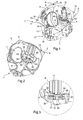
- la figure 1 est une vue en perspective d'une boîte d'encastrement selon l'invention, les pattes étant en position rétractée ;
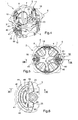
- la figure 2 est une vue en perspective de l'arrière de la boîte de la figure 1 ;
- la figure 3 est une vue agrandie, en perspective, d'une fenêtre du logement de la boîte, la patte étant en position rétractée ;
- la figure 4 est une vue similaire à celle de la figure 1, la patte étant sortie et remontée vers le bord en saillie ;
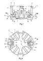
- la figure 5 est une vue en plan de l'intérieur et du bord en saillie comportant les quatre oreilles ;
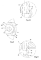
- la figure 6 est une vue agrandie du détail VI de la figure 5 ;
- la figure 7 est une vue en coupe de la boîte selon le plan repéré par VII-VII sur la figure 5 ;
- la figure 8 est une vue en coupe de la boîte selon le plan repéré par VIII-VIII sur la figure 7 ;
- la figure 9 est une vue agrandie du détail IX de la figure 8 ;
- la figure 10 est une vue en coupe du détail IX selon le plan repéré par X-X sur la figure 9 ;
- la figure 11 est une vue en coupe du détail VI selon le plan repéré par XI-XI sur la figure 6 ;
- la figure 12 est une vue similaire à celle de la figure 7 sur laquelle sont représentées les vis et la cloison dans laquelle la boîte est encastrée, les pattes et les oreilles serrant conjointement la cloison ;
- la figure 13 est une vue en élévation du corps de la boîte ;
- la figure 14 est une vue en élévation partielle du corps et de la cloison avant serrage, le contact entre le corps et la cloison se faisant au niveau de l'extrémité libre des oreilles ; et
- la figure 15 est une vue en élévation partielle du corps et de la cloison après serrage.
- Figure 1 is a perspective view of a flush mounting box according to the invention, the tabs being in the retracted position;
- Figure 2 is a perspective view of the rear of the box of Figure 1;
- Figure 3 is an enlarged view, in perspective, of a housing window of the box, the tab being in the retracted position;
- Figure 4 is a view similar to that of Figure 1, the tab being extended and raised to the projecting edge;
- Figure 5 is a plan view of the interior and the projecting edge including the four ears;
- Figure 6 is an enlarged view of detail VI of Figure 5;
- Figure 7 is a sectional view of the box according to the plane indicated by VII-VII in Figure 5;
- Figure 8 is a sectional view of the box in the plane indicated by VIII-VIII in Figure 7;
- Fig. 9 is an enlarged view of detail IX of Fig. 8;
- Figure 10 is a sectional view of detail IX in the plane marked XX in Figure 9;
- Figure 11 is a sectional view of detail VI in the plane indicated by XI-XI in Figure 6;
- Figure 12 is a view similar to that of Figure 7 on which are shown the screws and the partition in which the box is recessed, the legs and the ears together tightening the partition;
- Figure 13 is an elevational view of the body of the box;
- Figure 14 is a partial elevational view of the body and the partition before clamping, the contact between the body and the partition being at the free end of the ears; and
- Figure 15 is a partial elevational view of the body and the partition after tightening.
La boîte d'encastrement 1 selon l'invention est destinée à accueillir un appareil électrique encastré dans une cloison sèche.The
Elle comporte un corps 2 en matière plastique. Ce corps 2 comporte une paroi latérale 3 de forme globalement cylindrique, un fond 4 et une ouverture frontale opposée au fond 4. La paroi 3 présente un bord qui délimite l'ouverture. Ce bord comporte une collerette 5 qui s'étend transversalement à la paroi latérale 3, en saillie vers l'extérieur.It comprises a
La collerette 5 est fine et déborde peu de la paroi latérale 3. En chacun de quatre emplacements régulièrement répartis angulairement sur la périphérie de la collerette 5, s'étend une oreille 6 appartenant au bord.The
Chaque oreille 6 est sensiblement triangulaire et de même épaisseur que la collerette 5. Elle présente deux bords libres de même longueur et transversaux l'un par rapport à l'autre ainsi qu'une extrémité libre 9 formant pointe à l'écart de la paroi 3. L'angle existant entre les deux bords au niveau de l'extrémité 9 est arrondi.Each
Du fait de la répartition des oreilles 6 et de leur géométrie, les extrémités 9 forment les quatre coins d'un carré. En position encastrée de la boîte 1 et lorsqu'un appareil est disposé dans celle-ci, les oreilles 6 sont cachées derrière l'appareil présentant généralement une base de forme carrée de sorte qu'elles occupent une superficie maximale.Due to the distribution of the
Alors que la collerette 5 est plate, les oreilles 6 sont légèrement recourbées vers le plan comportant le fond 4.While the
Chaque oreille 6 présente une racine 13 vers la jonction avec la collerette 5 et chaque oreille 6 présente une courbure au niveau de la racine 13. Les courbures sont telles que les oreilles 6 sont orientées vers l'extérieur et vers le fond 4.Each
La paroi latérale 3 et le fond 4 présentent des parties défonçables 7 permettant, après enlèvement de ces parties défonçables 7, la mise en place de conducteurs d'arrivée et de départ à relier à l'appareil électrique.The
Les parties défonçables 7 comportent chacune deux portions sensiblement transversales l'une par rapport à l'autre, l'une des portions appartenant au fond 4 de la boîte 1, tandis que l'autre appartient à la paroi latérale 3. Chaque partie défonçable 7 est reliée par une zone sécable 8 au corps 2, l'une des zones sécables 8 reliant la partie défonçable 7 à la paroi latérale 3, l'autre zone sécable 8 reliant la partie défonçable 7 au fond 4.The
Les zones sécables 8 sont en matière plastique, les parties défonçables 7 et le corps 2 étant moulés d'une pièce.The
Les parties défonçables 7 et les découpes qui les accueillent sont ici de forme globalement ovale.The
L'angle existant entre la paroi latérale 3 et le fond 4 au niveau de leur raccordement est arrondi de sorte que l'insertion de la boîte 1 dans la cloison est facilitée.The angle between the
De manière connue en soi, la paroi latérale 3 porte sur sa surface intérieure deux surépaisseurs 10.In a manner known per se, the
Chaque surépaisseur 10 est fine et allongée, percée de trois trous côte à côte. Ces trous sont destinés à accueillir une vis de montage de l'appareil électrique dans la boîte 1. Vers le fond 4, les trous traversent la paroi 3 et débouchent sur l'extérieur de celle-ci du fait qu'en cette zone, la paroi 3 n'est formée que de la surépaisseur 10.Each
Les deux surépaisseurs 10 sont positionnées diamétralement opposées.The two
Chaque surépaisseur 10 présente sur sa surface intérieure à la boîte 1 des petits crans destinés à la fixation d'un appareil électrique.Each
La paroi 3 comporte également, sur sa surface extérieure, deux renfoncements 11 diamétralement opposés. Les deux renfoncements 11 et les deux surépaisseurs 10 sont alternés et régulièrement répartis sur la paroi 3. Et chaque oreille 6 est placée entre une surépaisseur 10 et un renfoncement 11.The
On décrit maintenant l'un quelconque des renfoncements 11.We now describe any of the
Celui-ci est semi-cylindrique. Il s'étend selon une direction axiale qui correspond à la direction des génératrices de la paroi 3.This one is semi-cylindrical. It extends in an axial direction corresponding to the direction of the generatrices of the
Le renfoncement 11 s'étend à partir de la collerette 5 en direction du fond 4. Vers le fond 4, le renfoncement 11 débouche sur l'une de deux fenêtres 12 que comporte la paroi 3. Du côté de la collerette 5, celui-ci se termine par un anneau dont le rayon intérieur est très inférieur à celui du renfoncement 11. L'ouverture centrale de l'anneau autorise le passage de la tige 15 d'une vis 16. Au dessus de cet anneau, la collerette 5 est ouverte sur un petit logement circulaire 17 permettant d'accueillir la tête de la vis 16. Ce logement circulaire 17 comporte, sensiblement dans le plan de la collerette 5, une petite saillie formant moyen d'encliquetage 19 pour la tête de la vis 16. Ainsi, une fois que la tige 15 est passée dans l'anneau et est accueillie dans le renfoncement 11 et que la tête est encliquetée dans son logement circulaire 17, la vis 16 est bloquée selon la direction axiale mais est toujours libre de pivoter sur elle-même.The
La fenêtre 12 présente une forme sensiblement rectangulaire. Sa hauteur selon la direction axiale est très inférieure à la hauteur du renfoncement 11. La fenêtre 12 est centrée transversalement à la direction axiale sur la tige 15 de la vis 16. Une avancée rectangulaire 18 de la paroi 3 vient rétrécir la dimension transversale de la fenêtre du côté de la fenêtre 12 le plus proche de la collerette 5.The
La fenêtre 12 comporte un bord 20 du côté du renfoncement 11, un bord 21 opposé au bord 20, un bord 22 en créneaux du côté de l'avancée 18 et un bord 23, droit, opposé au bord 22. Le bord 21 est à l'écart du plan comportant le fond 4.The
Comme on le voit sur la figure 2, sur sa surface intérieure, la paroi 3 présente, le long du bord 20, un rebord 25 en saillie.As seen in Figure 2, on its inner surface, the
Le rebord 25 s'étend transversalement à la paroi 3 vers l'intérieur sur une distance équivalente au rayon du renfoncement 11. Ainsi, le rebord 25 présente une portion de chaque côté du renfoncement 11. L'une de ces portions est plus longue que l'autre puisque le bord 20 n'est pas d'égale distance de part et d'autre du renfoncement 11 du fait de l'avancée 18.The
Le fond 4 comporte deux marches semi-circulaires 30, chacune s'étendant devant l'une des fenêtres 12. Les bords périphériques des marches 30 sont en regard l'un de l'autre.The
Chaque marche 30 atteint la hauteur du bord 21.Each
On décrit une quelconque des deux marches 30. Pour un observateur placé à l'intérieur du corps 2 et regardant vers le renfoncement 11, le plat de la marche 30 comporte deux zones latérales pleines et une zone centrale ouvrant sur un puits 31. La zone centrale s'étend de la fenêtre 12 jusqu'à la bordure périphérique.One of the two
Le puits 31 s'étend, selon la direction axiale, du bord 21 jusqu'au plan comportant le reste du fond 4.The well 31 extends in the axial direction from the
Lorsque l'observateur est placé à l'extérieur et regarde l'arrière de la marche 30, se présentent le puits 31 et, de part et d'autre de ce puits 31, deux renfoncements 32 dont le fond correspond aux deux zones latérales. Ces renfoncements 32 sont délimités par une bordure épaisse qui, le long de la périphérie semi-circulaire, correspond sensiblement au rattrapage de hauteur entre le haut de la marche 30 et le reste du fond 4.When the observer is placed outside and looks at the rear of the
La tige 15 de la vis 16 a une longueur correspondant sensiblement à la distance entre la collerette 5 et le fond 4 de sorte que lorsque la tête est encliquetée dans son logement 17, l'extrémité libre de la tige 15 est située dans le puits 31 sans en dépasser.The
La boîte 1 comporte également deux pattes de serrage 40 s'étendant principalement parallèlement au fond 4. Chaque patte 40 comporte une platine 41 en forme de secteur angulaire, globalement semi-cylindrique, légèrement plus petite que la marche 30. Les pattes 40 comportent également un bossage 42 présentant un moyeu 43 en son centre.The
Le bossage 42 s'étend selon la direction axiale sur une longueur plus importante que l'épaisseur de la platine 41.The
La platine 41 comporte un bord périphérique 44 et deux bords alignés 45, 46 s'étendant chacun du bossage 42 à l'une des extrémités du bord 44. Les bords 45, 46 sont alignés de part et d'autre du bossage 42.The
Lorsqu'un observateur regarde la fenêtre 12 de l'extérieur de la boîte, il voit à travers cette fenêtre 12 le bord 46 entier. En revanche, il ne voit pas l'extrémité du bord 45 au contact du bord périphérique 43. En effet, cette extrémité est cachée derrière l'avancée 18.When an observer looks at the
La patte 40 présente d'un côté une surface 47 globalement plate présentant deux renfoncements 49 de part et d'autre d'une zone centrale.The
La zone centrale comporte trois stries en saillie pour mieux agripper la surface intérieure de la cloison.The central zone has three protruding ridges to better grip the inner surface of the partition.
De l'autre côté, outre le bossage 42 faisant saillie, la platine 41 comporte une aile 48 selon la direction axiale se projetant du même côté du bossage 42.On the other side, in addition to the
L'aile 48 est positionnée au dos de la zone centrale et s'étend du bossage 42 jusqu'au bord périphérique 44 de la platine 41. Cette aile 48 est ici formée par une petite paroi en U en saillie par rapport à la platine 41.The
De part et d'autre de l'aile 48 et au centre de celle-ci, la platine 41 présente des renfoncements. Ces trois renfoncements s'étendent au dos de la zone centrale. Au dos des renfoncements 49, la surface de la patte 40 est plate.On both sides of the
Les différents renfoncements permettent notamment une économie de matière plastique.The various recesses allow in particular a saving of plastic material.
La patte 40 est reliée au corps 2 après le moulage par quatre liens sécables en matière plastique (figures 5, 10, 11). Deux liens 50 relient le rebord 25 de la fenêtre 12 respectivement au bord 45 et au bord 46 de la patte 40. La surface 47 de la patte 40 se trouve sensiblement dans le plan comportant le bord 20. Deux liens 51 relient l'extrémité libre du bossage 42 à la surface intérieure du puits 31, le bossage 42 rentrant légèrement dans le puits 31. Le sectionnement des liens est précisé ci-après.The
Chaque moyeu 43 accueille la tige 15 de la vis 16 de sorte que la patte 40 est positionnée à une hauteur déterminée de la tige 15.Each
On décrit maintenant en détail l'utilisation des pattes dans une telle boîte d'encastrement.The use of the tabs in such a flush-mounting box is now described in detail.
Préalablement à l'utilisation des pattes 40, la boîte d'encastrement 1 est insérée dans une ouverture de la cloison 60. Cette cloison 60 comporte une surface extérieure et une surface intérieure. L'ouverture dans la cloison 60 est une ouverture circulaire dont le diamètre est tel que lors de l'enfoncement de la boîte 1, le corps 2 est enfoncé à travers cette ouverture mais la collerette 5 et les oreilles 6 restent du côté de la surface extérieure. Le contact entre la surface extérieure et le bord en saillie du corps 2 est alors limité au contact avec les extrémités 9 des oreilles 6. La collerette 5 est légèrement à l'écart du plan de la surface avant. Les oreilles 6 étant fines et recourbées, elles sont flexibles. Chaque oreille 6 dispose d'une liberté de pivotement de quelques degrés autour de sa racine 13.Prior to the use of the
Ainsi, lorsque les pattes 40 viennent au contact de la surface intérieure de la cloison 60, comme on l'explique dans la suite, on continue à visser les pattes 40 de sorte que le serrage s'amplifie non pas par l'avancée des pattes 40 mais par l'aplatissement des oreilles 6 contre la surface avant. C'est-à-dire que les oreilles 6, qui étaient courbées vers le plan contenant le fond 4, sont alors aplaties dans le plan comportant la collerette 5 (figure 15). Les oreilles 6 épousent parfaitement la forme de la surface extérieure même si celle-ci présente quelques irrégularités.Thus, when the
Visuellement, l'utilisateur détecte le serrage suffisant des pattes lorsqu'il voit les oreilles 6 aplaties sur la cloison 60, contrairement aux boîtes connues dans lesquelles l'opérateur n'est pas informé. Dans ces boîtes, en continuant à serrer, la collerette 5 et les oreilles 6 se relèvent et risquent d'empêcher l'appareillage, que l'on souhaite disposer dans la boîte, d'être correctement plaqué contre la surface extérieure de la cloison.Visually, the user detects the sufficient clamping of the legs when he sees the
Pour revenir à l'utilisation des pattes 40, lorsque les liens 50, 51 sont rompus, la patte 40 est mobile à pivotement autour de la tige 15 entre une position rétractée dans laquelle elle est positionnée dans le corps 2 au-dessus de la marche 30 et une position sortie dans laquelle elle a pivoté d'un demi-tour et se retrouve à l'extérieur de la boîte 1. Ce pivotement s'effectue avec celui de la vis 16 qui pivote également, la patte 40 étant, dans ces deux positions, située à une hauteur déterminée de la tige 16.To return to the use of the
La patte 40 est également mobile à translation, principalement lorsqu'elle se trouve à l'extérieur du corps 2. Comme on le voit sur la figure 5, la patte 40 peut se déplacer vers une position plus haute sur la tige 15, à différents niveaux du renfoncement 11. Dans ce cas, la patte 40 subit une translation lorsque la tige 15 pivote.The
Comme on le voit sur la figure 2, à la première utilisation de la patte, en position rétractée initiale, la patte est reliée au corps 2 par les deux liens sécables 51 (figure 11) reliant l'extrémité libre du bossage 42 avec la paroi latérale du puits 31. Ces liens sécables 51 sont coupés par simple pivotement de la patte 30.As seen in Figure 2, the first use of the tab in the initial retracted position, the tab is connected to the
La patte 40 est initialement en position rétractée à l'intérieur de la boîte 1, avec la vis 16 positionnée dans le renfoncement 11 et traversant le moyeu 43 afin de pouvoir commander la patte 40. Cette patte 40 est dans sa position rétractée au droit de la fenêtre 12 et plus particulièrement au droit de la portion comprenant l'avancée 18.The
La tête de la vis 16 étant encliquetée dans son logement à l'aide d'un tournevis, lorsqu'on fait tourner cette vis 16, la patte 30 et la vis 16 commencent leur pivotement autour de l'axe de la tige de la vis. Les liens 51 se rompent.The head of the
Du fait des dimensions de la fenêtre 12, un seul sens de rotation de la vis 16, premier sens de rotation, permet de faire saillir la patte 40 au travers de la fenêtre 12 ; ce sens permet, dans un premier temps, au bord 45 de s'éloigner de l'avancée 18.Due to the dimensions of the
En continuant à visser dans le premier sens, on fait passer l'intégralité de la platine 41 à travers la fenêtre 12.Continuing to screw in the first direction, the
Une fois que la platine 41 est entièrement à l'extérieur, le bord latéral 46 vient buter contre l'avancée 18. La patte 40 ne peut plus pivoter. Durant toute cette étape, la patte 40 est restée à une hauteur constante (selon la direction axiale).Once the
En continuant à visser, la patte 40, dont le bord 46 est en butée, est contrainte de monter le long de la tige 15 de la vis 16. Du fait de sa position initiale du moyeu 43 (dans l'axe du renfoncement 11), celui-ci se trouve au contact du renfoncement 11. En continuant à monter le long de la vis 15, le moyeu 43 reste dans le renfoncement 11 et le bord latéral 46 est situé contre une portion de la paroi 3 proche du renfoncement 11. Le bord 46 continue de buter contre la paroi 3 tant que l'on continue le vissage de la vis 16.Continuing to screw, the
Ce vissage se poursuit jusqu'à ce que la patte 40 vienne en contact avec la surface intérieure de la paroi 60 dans laquelle on souhaite encastrer la boîte 1 (figure 12).This screwing continues until the
A partir de cette position, il est possible de faire redescendre la patte 40 toujours en utilisant un tournevis et en tournant la vis dans un deuxième sens de rotation.From this position, it is possible to lower the
De la même façon que la patte 40 était montée le long du renfoncement, elle descend vers la fenêtre 12.In the same way that the
Lors de cette descente, c'est le bord 45 qui vient en butée contre une portion de la paroi 3 adjacente au renfoncement 11 (de l'autre côté du renfoncement 11 par rapport à la montée).During this descent, it is the
Lorsque l'ensemble de la patte 40 est arrivé au droit de la fenêtre 12, la patte 40 cesse de descendre avec la rotation de la vis 16. Le bord 45 qui venait précédemment en butée ne trouve plus aucune résistance, la patte 40 ne fait que pivoter avec la vis 16.When the
Ainsi, lorsqu'on souhaite désencastrer la boîte 1, l'utilisateur peut visualiser la fin de la descente des pattes 40 puisque celles-ci arrivent dans l'intérieur du corps 2.Thus, when it is desired to disencase the
Le pivotement se fait jusqu'à ce que la patte soit en position rétractée et jusqu'à ce que ce bord 45 vienne buter sur la surface intérieure de l'avancée 18.The pivoting is done until the tab is in retracted position and until the
La patte 40 est en position rétractée, la manoeuvre peut s'arrêter. Toutefois, si l'on continue la rotation de la vis 16, la patte 40 étant en butée, celle-ci reprend sa descente le long de la vis 16.The
Lorsque la patte 40 est entièrement en regard de la portion de la fenêtre 12 ne comportant pas d'avancée 18, le bord 45 ne trouve plus d'obstacle venant en butée.When the
Toutefois, dans sa descente au droit de la fenêtre 12, il est arrivé un moment où l'aile 48 est arrivée dans le puits 31. Dès lors, la patte 40 est bloquée en pivotement par l'aile 48 qui vient buter contre une paroi du puits 31. La patte 40 est bloquée dans sa translation vers l'extrémité libre de la tige 15 de sorte que la patte 40 est imperdable.However, in its descent to the right of the
Lorsqu'on fait à nouveau pivoter la vis 16 dans le premier sens de rotation, l'aile 48 va venir en butée contre l'autre paroi du puits 31 forçant la patte 40 à remonter jusqu'à arriver à un niveau où l'aile 48 sort du puits 31. La patte 40 est alors en position rétractée.When the
Quelle que soit la position de la patte 40 sur la tige 16, cette patte 40 est toujours en butée contre un élément du corps 2 à l'exception de la hauteur unique à laquelle le passage à travers la fenêtre 12 est autorisé.Whatever the position of the
Du fait de ce passage à travers la fenêtre 12, la distance entre le moyeu 43 et le bord périphérique 44 de la patte 40 ne doit pas être supérieur à la distance entre le moyeu 43 et le bord 23. De par cette structure, une platine en forme de secteur angulaire, telle que la platine 41, avec un rayon adapté, permet d'obtenir une patte 40 avec la plus grande surface de serrage. En position de serrage de la cloison, les efforts de serrage sur la surface intérieure sont répartis sur la surface importante de la patte et les efforts sur la surface avant sont répartis sur les quatre oreilles 6, de sorte que le risque d'endommager la cloison est limité.Due to this passage through the
Selon une variante du mode de réalisation, les oreilles présentent une première portion du côté de leur racine orientée vers l'extérieur et à l'opposé du fond et une deuxième portion orientée vers l'extérieur et vers le fond de sorte qu'elles présentent un profil bombé.According to a variant of the embodiment, the ears have a first portion on the side of their root facing outwards and away from the bottom and a second portion facing outwards and toward the bottom so that they present a curved profile.
Selon une autre variante du mode de réalisation, la collerette est discontinue, voire limitée aux seuls emplacements des oreilles.According to another variant of the embodiment, the collar is discontinuous, even limited to the only locations of the ears.
De nombreuses autres variantes sont possibles en fonction des circonstances, notamment dans la constitution des pattes, qui peuvent par exemple être remplacées par une griffe en métal, voire dans les moyens de serrage, dans la constitution du logement ou du corps qui peut être par exemple dédoublé pour accueillir deux appareils électriques.Many other variants are possible depending on the circumstances, especially in the constitution of the legs, which may for example be replaced by a metal claw, or in the clamping means, in the constitution of the housing or the body which may be for example split to accommodate two electrical appliances.
Claims (7)
Applications Claiming Priority (1)
| Application Number | Priority Date | Filing Date | Title |
|---|---|---|---|
| FR0504681A FR2885745B1 (en) | 2005-05-10 | 2005-05-10 | RECOVERY BOX AND METHOD OF MANUFACTURE |
Publications (3)
| Publication Number | Publication Date |
|---|---|
| EP1722453A2 true EP1722453A2 (en) | 2006-11-15 |
| EP1722453A3 EP1722453A3 (en) | 2010-11-10 |
| EP1722453B1 EP1722453B1 (en) | 2013-03-20 |
Family
ID=35448326
Family Applications (2)
| Application Number | Title | Priority Date | Filing Date |
|---|---|---|---|
| EP20060290668 Not-in-force EP1722453B1 (en) | 2005-05-10 | 2006-04-24 | Flush mounted box |
| EP06290667.2A Not-in-force EP1722472B1 (en) | 2005-05-10 | 2006-04-24 | Flush mounted box and method of production |
Family Applications After (1)
| Application Number | Title | Priority Date | Filing Date |
|---|---|---|---|
| EP06290667.2A Not-in-force EP1722472B1 (en) | 2005-05-10 | 2006-04-24 | Flush mounted box and method of production |
Country Status (4)
| Country | Link |
|---|---|
| EP (2) | EP1722453B1 (en) |
| ES (2) | ES2406941T3 (en) |
| FR (1) | FR2885745B1 (en) |
| HU (1) | HUE026479T2 (en) |
Cited By (9)
| Publication number | Priority date | Publication date | Assignee | Title |
|---|---|---|---|---|
| AT504355B1 (en) * | 2006-12-18 | 2008-05-15 | Putz Georg | WALL. WALL-BOX FOR ELECTRIC ARMATURES |
| GB2469515A (en) * | 2009-04-17 | 2010-10-20 | Demetri Kiloni | Electrical back box with flange |
| FR2963994A1 (en) * | 2010-08-17 | 2012-02-24 | Cooper Technologies Co | Box for use in hole of plaster or masonry dry wall to accommodate electric apparatus, has stop faces and stop defining longitudinal grooves formed in edges to guide sliding of tab in work position during screwing/unscrewing of screw |
| FR2963995A1 (en) * | 2010-08-17 | 2012-02-24 | Cooper Technologies Co | Box for use in hole of plaster or masonry drywall to accommodate electric apparatus, has tab occupying rest position in which tab is rotated toward center of box and housed in fold housing whose portion is formed from elastomer |
| ITBS20120053A1 (en) * | 2012-04-05 | 2013-10-06 | Ave Spa | BUILT-IN ELECTRIC BOX FOR LIGHT WALLS |
| ITMI20122021A1 (en) * | 2012-11-28 | 2014-05-29 | Gewiss Spa | BOX FOR INSTALLATION AND WIRING OF ELECTRICAL DEVICES, SUITABLE FOR MOUNTING IN THE RECESSED WAY |
| WO2019068324A1 (en) | 2017-10-04 | 2019-04-11 | Oblamatik Ag | Installation sleeve |
| WO2020016311A1 (en) * | 2018-07-18 | 2020-01-23 | Schneider Electric Industries Sas | Housing |
| EP3540884B1 (en) | 2018-03-14 | 2021-11-24 | Kaiser GmbH & Co. KG | Installation box and inlet for installation box |
Families Citing this family (2)
| Publication number | Priority date | Publication date | Assignee | Title |
|---|---|---|---|---|
| FR3011139B1 (en) * | 2013-09-25 | 2017-05-26 | Legrand France | ELECTRICAL ENCLOSURE BOX |
| US11088518B2 (en) | 2017-10-06 | 2021-08-10 | Lutron Technology Company Llc | Mounting mechanism for an electrical device |
Citations (2)
| Publication number | Priority date | Publication date | Assignee | Title |
|---|---|---|---|---|
| FR2670625A1 (en) * | 1990-12-14 | 1992-06-19 | Merlin Gerin | Universal fitting box for electrical apparatus |
| DE29622171U1 (en) * | 1996-12-20 | 1997-03-13 | Kaiser GmbH & Co KG, 58579 Schalksmühle | Electrical junction box, such as switch box, junction box or the like. |
Family Cites Families (5)
| Publication number | Priority date | Publication date | Assignee | Title |
|---|---|---|---|---|
| US2047294A (en) * | 1935-06-28 | 1936-07-14 | Joseph E Simek | Clamping device |
| US2875914A (en) * | 1956-10-31 | 1959-03-03 | Christopher C Buckels | Electrical outlet box |
| DE4241390C2 (en) * | 1992-12-09 | 1997-11-20 | Kaiser Gmbh & Co Kg | Electrical cavity wall box, such as switch box, junction box or the like. |
| FR2725318B1 (en) * | 1994-10-04 | 1996-10-31 | Schneider Electric Sa | BUILT-IN BOX FOR ELECTRICAL EQUIPMENT |
| FR2780567B1 (en) * | 1998-06-29 | 2000-09-15 | Alombard Sa | RECESSED BOX FOR DRY WALLS |
-
2005
- 2005-05-10 FR FR0504681A patent/FR2885745B1/en not_active Expired - Fee Related
-
2006
- 2006-04-24 ES ES06290668T patent/ES2406941T3/en active Active
- 2006-04-24 ES ES06290667.2T patent/ES2550430T3/en active Active
- 2006-04-24 HU HUE06290667A patent/HUE026479T2/en unknown
- 2006-04-24 EP EP20060290668 patent/EP1722453B1/en not_active Not-in-force
- 2006-04-24 EP EP06290667.2A patent/EP1722472B1/en not_active Not-in-force
Patent Citations (2)
| Publication number | Priority date | Publication date | Assignee | Title |
|---|---|---|---|---|
| FR2670625A1 (en) * | 1990-12-14 | 1992-06-19 | Merlin Gerin | Universal fitting box for electrical apparatus |
| DE29622171U1 (en) * | 1996-12-20 | 1997-03-13 | Kaiser GmbH & Co KG, 58579 Schalksmühle | Electrical junction box, such as switch box, junction box or the like. |
Cited By (11)
| Publication number | Priority date | Publication date | Assignee | Title |
|---|---|---|---|---|
| AT504355B1 (en) * | 2006-12-18 | 2008-05-15 | Putz Georg | WALL. WALL-BOX FOR ELECTRIC ARMATURES |
| GB2469515A (en) * | 2009-04-17 | 2010-10-20 | Demetri Kiloni | Electrical back box with flange |
| FR2963994A1 (en) * | 2010-08-17 | 2012-02-24 | Cooper Technologies Co | Box for use in hole of plaster or masonry dry wall to accommodate electric apparatus, has stop faces and stop defining longitudinal grooves formed in edges to guide sliding of tab in work position during screwing/unscrewing of screw |
| FR2963995A1 (en) * | 2010-08-17 | 2012-02-24 | Cooper Technologies Co | Box for use in hole of plaster or masonry drywall to accommodate electric apparatus, has tab occupying rest position in which tab is rotated toward center of box and housed in fold housing whose portion is formed from elastomer |
| ITBS20120053A1 (en) * | 2012-04-05 | 2013-10-06 | Ave Spa | BUILT-IN ELECTRIC BOX FOR LIGHT WALLS |
| ITMI20122021A1 (en) * | 2012-11-28 | 2014-05-29 | Gewiss Spa | BOX FOR INSTALLATION AND WIRING OF ELECTRICAL DEVICES, SUITABLE FOR MOUNTING IN THE RECESSED WAY |
| EP2738896A1 (en) | 2012-11-28 | 2014-06-04 | GEWISS S.p.A. | Box for installing and wiring electrical devices adapted to be embedded |
| WO2019068324A1 (en) | 2017-10-04 | 2019-04-11 | Oblamatik Ag | Installation sleeve |
| US11705705B2 (en) | 2017-10-04 | 2023-07-18 | Oblamatik Ag | Mounting sleeve |
| EP3540884B1 (en) | 2018-03-14 | 2021-11-24 | Kaiser GmbH & Co. KG | Installation box and inlet for installation box |
| WO2020016311A1 (en) * | 2018-07-18 | 2020-01-23 | Schneider Electric Industries Sas | Housing |
Also Published As
| Publication number | Publication date |
|---|---|
| FR2885745A1 (en) | 2006-11-17 |
| ES2550430T3 (en) | 2015-11-06 |
| EP1722453A3 (en) | 2010-11-10 |
| HUE026479T2 (en) | 2016-06-28 |
| FR2885745B1 (en) | 2007-08-10 |
| EP1722472A3 (en) | 2010-08-11 |
| EP1722453B1 (en) | 2013-03-20 |
| EP1722472B1 (en) | 2015-07-29 |
| EP1722472A2 (en) | 2006-11-15 |
| ES2406941T3 (en) | 2013-06-10 |
Similar Documents
| Publication | Publication Date | Title |
|---|---|---|
| EP1722453B1 (en) | Flush mounted box | |
| EP0633197A1 (en) | Combination of a, by relative rotation, interlocking container and closure, as well as the application of such a combination | |
| EP3435812B1 (en) | Container for food use | |
| EP0053543A2 (en) | Devices for fixing objects to sheet metals accessible from one side only | |
| FR2924867A1 (en) | ANGLE ACCESSORY FOR CHUTE | |
| EP2068409B1 (en) | Corner accessory for gutters with swinging flaps | |
| FR2895939A1 (en) | CROCHET OF RECEPTION OF A JOINT TOURILLON | |
| EP2966741B1 (en) | apparatus support to be mounted in a flush mounted box and electrical apparatus having such a support. | |
| EP1775814B1 (en) | Flush-mounted box with drive clamping screw | |
| EP1775815B1 (en) | Flush-mounted box with optimal fixation | |
| CA2515573A1 (en) | Fixing device with a clip | |
| EP2112734B1 (en) | Electrical device for being added to a recessed box | |
| FR2796367A1 (en) | Plug for sealing holes in car bodywork comprises skirt with a peripheral lip which fits against bodywork, series of teeth pivoted on skirt and central button which pushes them outwards that plug is locked in hole | |
| FR3120998A1 (en) | Built-in electrical device | |
| EP3115515B1 (en) | Pavement manhole with frame and panel | |
| EP2431641B1 (en) | Fixing device of a connection piece of a fluid carrying pipe to a hollow wall | |
| EP3822427B1 (en) | Spacing accessory for lining a wall | |
| FR2972860A1 (en) | ELECTRICAL CONNECTION DEVICE FOR GROUNDING METAL STRUCTURES | |
| FR2883340A1 (en) | DEVICE FOR FASTENING A FASTENING RING ON A CARRIER MEMBER AND SUPPORT COMPRISING SAME | |
| FR3116455A1 (en) | Tube cutting device | |
| EP3506443A1 (en) | Variable depth electrical box | |
| FR2866083A1 (en) | Remote selector`s base and cover fixation device, has cover with two legs having respective hooks situated on both sides of bridge piece of base that partially blocks opening of bore, in locked position of base and cover | |
| EP3428083A1 (en) | Container at least partially made of metal, comprising a plurality of parts, provided with a system for assembling said parts | |
| FR2766025A1 (en) | Electrical wiring installation wall-box for dry-construction wall | |
| EP2200415A1 (en) | Box commprising a cover for housing an electric apparatus |
Legal Events
| Date | Code | Title | Description |
|---|---|---|---|
| PUAI | Public reference made under article 153(3) epc to a published international application that has entered the european phase |
Free format text: ORIGINAL CODE: 0009012 |
|
| AK | Designated contracting states |
Kind code of ref document: A2 Designated state(s): AT BE BG CH CY CZ DE DK EE ES FI FR GB GR HU IE IS IT LI LT LU LV MC NL PL PT RO SE SI SK TR |
|
| AX | Request for extension of the european patent |
Extension state: AL BA HR MK YU |
|
| PUAL | Search report despatched |
Free format text: ORIGINAL CODE: 0009013 |
|
| AK | Designated contracting states |
Kind code of ref document: A3 Designated state(s): AT BE BG CH CY CZ DE DK EE ES FI FR GB GR HU IE IS IT LI LT LU LV MC NL PL PT RO SE SI SK TR |
|
| AX | Request for extension of the european patent |
Extension state: AL BA HR MK YU |
|
| 17P | Request for examination filed |
Effective date: 20110202 |
|
| AKX | Designation fees paid |
Designated state(s): AT BE BG CH CY CZ DE DK EE ES FI FR GB GR HU IE IS IT LI LT LU LV MC NL PL PT RO SE SI SK TR |
|
| GRAP | Despatch of communication of intention to grant a patent |
Free format text: ORIGINAL CODE: EPIDOSNIGR1 |
|
| GRAS | Grant fee paid |
Free format text: ORIGINAL CODE: EPIDOSNIGR3 |
|
| GRAA | (expected) grant |
Free format text: ORIGINAL CODE: 0009210 |
|
| AK | Designated contracting states |
Kind code of ref document: B1 Designated state(s): AT BE BG CH CY CZ DE DK EE ES FI FR GB GR HU IE IS IT LI LT LU LV MC NL PL PT RO SE SI SK TR |
|
| REG | Reference to a national code |
Ref country code: GB Ref legal event code: FG4D Free format text: NOT ENGLISH |
|
| REG | Reference to a national code |
Ref country code: CH Ref legal event code: EP |
|
| REG | Reference to a national code |
Ref country code: IE Ref legal event code: FG4D Free format text: LANGUAGE OF EP DOCUMENT: FRENCH |
|
| REG | Reference to a national code |
Ref country code: AT Ref legal event code: REF Ref document number: 602580 Country of ref document: AT Kind code of ref document: T Effective date: 20130415 |
|
| REG | Reference to a national code |
Ref country code: DE Ref legal event code: R096 Ref document number: 602006035156 Country of ref document: DE Effective date: 20130516 |
|
| REG | Reference to a national code |
Ref country code: ES Ref legal event code: FG2A Ref document number: 2406941 Country of ref document: ES Kind code of ref document: T3 Effective date: 20130610 |
|
| PG25 | Lapsed in a contracting state [announced via postgrant information from national office to epo] |
Ref country code: LT Free format text: LAPSE BECAUSE OF FAILURE TO SUBMIT A TRANSLATION OF THE DESCRIPTION OR TO PAY THE FEE WITHIN THE PRESCRIBED TIME-LIMIT Effective date: 20130320 Ref country code: BG Free format text: LAPSE BECAUSE OF FAILURE TO SUBMIT A TRANSLATION OF THE DESCRIPTION OR TO PAY THE FEE WITHIN THE PRESCRIBED TIME-LIMIT Effective date: 20130620 Ref country code: SE Free format text: LAPSE BECAUSE OF FAILURE TO SUBMIT A TRANSLATION OF THE DESCRIPTION OR TO PAY THE FEE WITHIN THE PRESCRIBED TIME-LIMIT Effective date: 20130320 |
|
| PGFP | Annual fee paid to national office [announced via postgrant information from national office to epo] |
Ref country code: DE Payment date: 20130529 Year of fee payment: 8 |
|
| REG | Reference to a national code |
Ref country code: AT Ref legal event code: MK05 Ref document number: 602580 Country of ref document: AT Kind code of ref document: T Effective date: 20130320 |
|
| REG | Reference to a national code |
Ref country code: LT Ref legal event code: MG4D |
|
| PG25 | Lapsed in a contracting state [announced via postgrant information from national office to epo] |
Ref country code: FI Free format text: LAPSE BECAUSE OF FAILURE TO SUBMIT A TRANSLATION OF THE DESCRIPTION OR TO PAY THE FEE WITHIN THE PRESCRIBED TIME-LIMIT Effective date: 20130320 Ref country code: GR Free format text: LAPSE BECAUSE OF FAILURE TO SUBMIT A TRANSLATION OF THE DESCRIPTION OR TO PAY THE FEE WITHIN THE PRESCRIBED TIME-LIMIT Effective date: 20130621 Ref country code: LV Free format text: LAPSE BECAUSE OF FAILURE TO SUBMIT A TRANSLATION OF THE DESCRIPTION OR TO PAY THE FEE WITHIN THE PRESCRIBED TIME-LIMIT Effective date: 20130320 Ref country code: SI Free format text: LAPSE BECAUSE OF FAILURE TO SUBMIT A TRANSLATION OF THE DESCRIPTION OR TO PAY THE FEE WITHIN THE PRESCRIBED TIME-LIMIT Effective date: 20130320 |
|
| REG | Reference to a national code |
Ref country code: NL Ref legal event code: VDEP Effective date: 20130320 |
|
| PG25 | Lapsed in a contracting state [announced via postgrant information from national office to epo] |
Ref country code: SK Free format text: LAPSE BECAUSE OF FAILURE TO SUBMIT A TRANSLATION OF THE DESCRIPTION OR TO PAY THE FEE WITHIN THE PRESCRIBED TIME-LIMIT Effective date: 20130320 Ref country code: CZ Free format text: LAPSE BECAUSE OF FAILURE TO SUBMIT A TRANSLATION OF THE DESCRIPTION OR TO PAY THE FEE WITHIN THE PRESCRIBED TIME-LIMIT Effective date: 20130320 Ref country code: EE Free format text: LAPSE BECAUSE OF FAILURE TO SUBMIT A TRANSLATION OF THE DESCRIPTION OR TO PAY THE FEE WITHIN THE PRESCRIBED TIME-LIMIT Effective date: 20130320 Ref country code: NL Free format text: LAPSE BECAUSE OF FAILURE TO SUBMIT A TRANSLATION OF THE DESCRIPTION OR TO PAY THE FEE WITHIN THE PRESCRIBED TIME-LIMIT Effective date: 20130320 Ref country code: AT Free format text: LAPSE BECAUSE OF FAILURE TO SUBMIT A TRANSLATION OF THE DESCRIPTION OR TO PAY THE FEE WITHIN THE PRESCRIBED TIME-LIMIT Effective date: 20130320 Ref country code: PT Free format text: LAPSE BECAUSE OF FAILURE TO SUBMIT A TRANSLATION OF THE DESCRIPTION OR TO PAY THE FEE WITHIN THE PRESCRIBED TIME-LIMIT Effective date: 20130722 Ref country code: RO Free format text: LAPSE BECAUSE OF FAILURE TO SUBMIT A TRANSLATION OF THE DESCRIPTION OR TO PAY THE FEE WITHIN THE PRESCRIBED TIME-LIMIT Effective date: 20130320 Ref country code: IS Free format text: LAPSE BECAUSE OF FAILURE TO SUBMIT A TRANSLATION OF THE DESCRIPTION OR TO PAY THE FEE WITHIN THE PRESCRIBED TIME-LIMIT Effective date: 20130720 |
|
| PG25 | Lapsed in a contracting state [announced via postgrant information from national office to epo] |
Ref country code: PL Free format text: LAPSE BECAUSE OF FAILURE TO SUBMIT A TRANSLATION OF THE DESCRIPTION OR TO PAY THE FEE WITHIN THE PRESCRIBED TIME-LIMIT Effective date: 20130320 Ref country code: CY Free format text: LAPSE BECAUSE OF FAILURE TO SUBMIT A TRANSLATION OF THE DESCRIPTION OR TO PAY THE FEE WITHIN THE PRESCRIBED TIME-LIMIT Effective date: 20130320 |
|
| REG | Reference to a national code |
Ref country code: CH Ref legal event code: PL |
|
| PG25 | Lapsed in a contracting state [announced via postgrant information from national office to epo] |
Ref country code: MC Free format text: LAPSE BECAUSE OF FAILURE TO SUBMIT A TRANSLATION OF THE DESCRIPTION OR TO PAY THE FEE WITHIN THE PRESCRIBED TIME-LIMIT Effective date: 20130320 |
|
| PLBE | No opposition filed within time limit |
Free format text: ORIGINAL CODE: 0009261 |
|
| STAA | Information on the status of an ep patent application or granted ep patent |
Free format text: STATUS: NO OPPOSITION FILED WITHIN TIME LIMIT |
|
| REG | Reference to a national code |
Ref country code: IE Ref legal event code: MM4A |
|
| PG25 | Lapsed in a contracting state [announced via postgrant information from national office to epo] |
Ref country code: DK Free format text: LAPSE BECAUSE OF FAILURE TO SUBMIT A TRANSLATION OF THE DESCRIPTION OR TO PAY THE FEE WITHIN THE PRESCRIBED TIME-LIMIT Effective date: 20130320 Ref country code: CH Free format text: LAPSE BECAUSE OF NON-PAYMENT OF DUE FEES Effective date: 20130430 Ref country code: LI Free format text: LAPSE BECAUSE OF NON-PAYMENT OF DUE FEES Effective date: 20130430 |
|
| 26N | No opposition filed |
Effective date: 20140102 |
|
| GBPC | Gb: european patent ceased through non-payment of renewal fee |
Effective date: 20130620 |
|
| REG | Reference to a national code |
Ref country code: DE Ref legal event code: R097 Ref document number: 602006035156 Country of ref document: DE Effective date: 20140102 |
|
| PG25 | Lapsed in a contracting state [announced via postgrant information from national office to epo] |
Ref country code: IE Free format text: LAPSE BECAUSE OF NON-PAYMENT OF DUE FEES Effective date: 20130424 Ref country code: GB Free format text: LAPSE BECAUSE OF NON-PAYMENT OF DUE FEES Effective date: 20130620 |
|
| REG | Reference to a national code |
Ref country code: DE Ref legal event code: R119 Ref document number: 602006035156 Country of ref document: DE |
|
| REG | Reference to a national code |
Ref country code: DE Ref legal event code: R119 Ref document number: 602006035156 Country of ref document: DE Effective date: 20141101 |
|
| PG25 | Lapsed in a contracting state [announced via postgrant information from national office to epo] |
Ref country code: DE Free format text: LAPSE BECAUSE OF NON-PAYMENT OF DUE FEES Effective date: 20141101 |
|
| PG25 | Lapsed in a contracting state [announced via postgrant information from national office to epo] |
Ref country code: TR Free format text: LAPSE BECAUSE OF FAILURE TO SUBMIT A TRANSLATION OF THE DESCRIPTION OR TO PAY THE FEE WITHIN THE PRESCRIBED TIME-LIMIT Effective date: 20130320 |
|
| PG25 | Lapsed in a contracting state [announced via postgrant information from national office to epo] |
Ref country code: LU Free format text: LAPSE BECAUSE OF NON-PAYMENT OF DUE FEES Effective date: 20130424 Ref country code: HU Free format text: LAPSE BECAUSE OF FAILURE TO SUBMIT A TRANSLATION OF THE DESCRIPTION OR TO PAY THE FEE WITHIN THE PRESCRIBED TIME-LIMIT; INVALID AB INITIO Effective date: 20060424 |
|
| REG | Reference to a national code |
Ref country code: FR Ref legal event code: PLFP Year of fee payment: 11 |
|
| PGFP | Annual fee paid to national office [announced via postgrant information from national office to epo] |
Ref country code: ES Payment date: 20160504 Year of fee payment: 11 |
|
| PGFP | Annual fee paid to national office [announced via postgrant information from national office to epo] |
Ref country code: IT Payment date: 20160411 Year of fee payment: 11 Ref country code: BE Payment date: 20160421 Year of fee payment: 11 |
|
| REG | Reference to a national code |
Ref country code: FR Ref legal event code: PLFP Year of fee payment: 12 |
|
| REG | Reference to a national code |
Ref country code: BE Ref legal event code: MM Effective date: 20170430 |
|
| REG | Reference to a national code |
Ref country code: FR Ref legal event code: PLFP Year of fee payment: 13 |
|
| PG25 | Lapsed in a contracting state [announced via postgrant information from national office to epo] |
Ref country code: BE Free format text: LAPSE BECAUSE OF NON-PAYMENT OF DUE FEES Effective date: 20170430 Ref country code: IT Free format text: LAPSE BECAUSE OF NON-PAYMENT OF DUE FEES Effective date: 20170424 |
|
| REG | Reference to a national code |
Ref country code: ES Ref legal event code: FD2A Effective date: 20180705 |
|
| PG25 | Lapsed in a contracting state [announced via postgrant information from national office to epo] |
Ref country code: ES Free format text: LAPSE BECAUSE OF NON-PAYMENT OF DUE FEES Effective date: 20170425 |
|
| PGFP | Annual fee paid to national office [announced via postgrant information from national office to epo] |
Ref country code: FR Payment date: 20200316 Year of fee payment: 15 |
|
| PG25 | Lapsed in a contracting state [announced via postgrant information from national office to epo] |
Ref country code: FR Free format text: LAPSE BECAUSE OF NON-PAYMENT OF DUE FEES Effective date: 20210430 |