EP1722145A2 - Rohrelement mit Schutzelement - Google Patents
Rohrelement mit Schutzelement Download PDFInfo
- Publication number
- EP1722145A2 EP1722145A2 EP06006246A EP06006246A EP1722145A2 EP 1722145 A2 EP1722145 A2 EP 1722145A2 EP 06006246 A EP06006246 A EP 06006246A EP 06006246 A EP06006246 A EP 06006246A EP 1722145 A2 EP1722145 A2 EP 1722145A2
- Authority
- EP
- European Patent Office
- Prior art keywords
- pipe
- protective
- clamping
- element according
- leg
- Prior art date
- Legal status (The legal status is an assumption and is not a legal conclusion. Google has not performed a legal analysis and makes no representation as to the accuracy of the status listed.)
- Granted
Links
- 238000004519 manufacturing process Methods 0.000 claims abstract description 10
- 239000002184 metal Substances 0.000 claims abstract description 7
- 229910052751 metal Inorganic materials 0.000 claims abstract description 7
- 230000001681 protective effect Effects 0.000 claims description 78
- 238000003780 insertion Methods 0.000 claims description 16
- 230000037431 insertion Effects 0.000 claims description 16
- 210000000078 claw Anatomy 0.000 claims description 12
- 230000013011 mating Effects 0.000 claims description 11
- 239000011324 bead Substances 0.000 claims description 9
- 239000004033 plastic Substances 0.000 claims description 7
- 230000006378 damage Effects 0.000 claims description 6
- 229910000881 Cu alloy Inorganic materials 0.000 claims description 3
- 239000004743 Polypropylene Substances 0.000 claims description 3
- -1 polypropylene Polymers 0.000 claims description 3
- 229920001155 polypropylene Polymers 0.000 claims description 3
- 239000010935 stainless steel Substances 0.000 claims description 3
- 229910001220 stainless steel Inorganic materials 0.000 claims description 3
- 229910000760 Hardened steel Inorganic materials 0.000 claims description 2
- 229910000831 Steel Inorganic materials 0.000 claims description 2
- 238000005452 bending Methods 0.000 claims description 2
- 239000007788 liquid Substances 0.000 claims description 2
- 239000010959 steel Substances 0.000 claims description 2
- 239000011253 protective coating Substances 0.000 claims 3
- 230000001419 dependent effect Effects 0.000 claims 1
- 238000007598 dipping method Methods 0.000 claims 1
- 238000010422 painting Methods 0.000 claims 1
- 238000005507 spraying Methods 0.000 claims 1
- 208000027418 Wounds and injury Diseases 0.000 description 5
- 208000014674 injury Diseases 0.000 description 5
- 230000000694 effects Effects 0.000 description 4
- 239000000463 material Substances 0.000 description 4
- 239000011248 coating agent Substances 0.000 description 2
- 238000000576 coating method Methods 0.000 description 2
- 230000006835 compression Effects 0.000 description 1
- 238000007906 compression Methods 0.000 description 1
- 238000000926 separation method Methods 0.000 description 1
- 238000007493 shaping process Methods 0.000 description 1
- 238000003466 welding Methods 0.000 description 1
Images

Classifications
-
- F—MECHANICAL ENGINEERING; LIGHTING; HEATING; WEAPONS; BLASTING
- F16—ENGINEERING ELEMENTS AND UNITS; GENERAL MEASURES FOR PRODUCING AND MAINTAINING EFFECTIVE FUNCTIONING OF MACHINES OR INSTALLATIONS; THERMAL INSULATION IN GENERAL
- F16L—PIPES; JOINTS OR FITTINGS FOR PIPES; SUPPORTS FOR PIPES, CABLES OR PROTECTIVE TUBING; MEANS FOR THERMAL INSULATION IN GENERAL
- F16L21/00—Joints with sleeve or socket
- F16L21/08—Joints with sleeve or socket with additional locking means
-
- E—FIXED CONSTRUCTIONS
- E04—BUILDING
- E04D—ROOF COVERINGS; SKY-LIGHTS; GUTTERS; ROOF-WORKING TOOLS
- E04D13/00—Special arrangements or devices in connection with roof coverings; Protection against birds; Roof drainage ; Sky-lights
- E04D13/04—Roof drainage; Drainage fittings in flat roofs, balconies or the like
- E04D13/08—Down pipes; Special clamping means therefor
- E04D2013/0846—Interconnecting down pipe parts
Definitions
- the present invention relates to a pipe element as a pipe component of a plug-in system comprising at least two pipe components for producing a pipe system, in particular as part of a roof drainage system, wherein the pipe components can be connected to one another for producing a plug connection and wherein the pipe element has a groove formed in particular as a bead at a plug-in end, in which a fuse of the connector serving clamping element, in particular of metal, is arranged.
- Such a tubular element is as a component of a pending in the German patent application no. 10353660.4 or in the European Patent Application 04025417.9 mentioned the Applicant claimed piping system for the discharge of liquid.
- the content of these two patent applications is hereby incorporated into the present application.
- Object of the present invention is therefore to provide a tubular element which allows both an improved, easy to assemble and in particular optically inconspicuous connector security, as well as space saving stored or transported, the risk of injury in the handling of such a tubular element reduced shall be.
- the clamping element according to the invention has a protective element that can be removed from a protective position before the connector is produced.
- a protective element that can be removed from a protective position before the connector is produced.
- the plug-in end of the tubular element can be designed as a plug-in end which can be received in the plug-in end of the other tube component, wherein the groove, in particular formed as a bead of the tubular element extends radially inward.
- the mating end of the tubular element has an insertion opening in which the mating end of the other tube component can be received, wherein the particular formed as a bead groove of the tubular element extends radially outward.
- the clamping element can be fixed in a form-fitting manner on the pipe element, in particular riveted. This also ensures that the clamping element during storage, during transport and final assembly is not accidentally from Pipe element is removed.
- the clamping element has at least one, in particular, sharp-edged claw section, with which it extends radially out of the groove of the tubular element, in such a way that the claw section can engage in engagement with the respective other tube component at its plug end to counteract a separation movement of the pipe elements relative to each other.
- the Krallabites is oriented with the protective element removed before mating the tube components orthogonal to the tube element axis or obliquely in the axial direction away from the front end of the groove with the clamping member received therein having plug of the tubular element, so that he upon mating of the tube member and the other tube component of the other tube component while maintaining the mutual action between the claw portion and the other tube component at least partially displaced into the groove and thereby axially in the direction away from the front end of the groove having plug-in end of a tubular element ,
- the claw section may have a toothing, wherein the teeth of such a toothing engage in claw-like or hook-like manner with the other tube component to be attached to the tube element.
- the clamping element may comprise according to an advantageous embodiment of the tubular element at least one tongue with the claw portion at one of its ends, wherein the tongue is in particular angled several times.
- a tongue is easy to produce in terms of production, and the rigidity of the clamping element and thus the strength of the clamping effect can be influenced by the particularly multiple angling.
- the clamping element as in particular interrupted ring element is formed, which is received in a circumferential groove on the circumference of the tubular element.
- the pipe element is formed of metal, in particular stainless steel or a copper alloy.
- the clamping element may be formed of a steel, in particular of hardened steel.
- the pipe element is a drain pipe for attachment to a gutter element, wherein the pipe member is to attach the other pipe component in the form of a drain pipe bend.
- the protective element attached to the pipe element may be substantially U-shaped, wherein it has a protective leg and a holding leg, which are connected to each other via a connecting portion.
- the protective element is integrally formed, in particular as a clip.
- a plastic in particular polypropylene, and / or rubber may be used.
- the clamping element between the protective leg and the holding leg is arranged, wherein the holding leg and the protective leg are biased by means of the connecting portion against each other, so that they exert on the clamping element a compressive force, which serves to fix the protective element on the tubular element.
- a compressive force which serves to fix the protective element on the tubular element.
- the connecting portion may be arcuate, and in particular in its arcuate curvature region having an at least partially enlarged cross-sectional area in order to accommodate in the connecting portion acting bending stresses, which press when Vonchroweg of the retaining leg and the protective leg against the pressure force arise.
- the Schutzschenkei-preferably starting from the connecting portion is substantially rectilinear, whereby a good stackability of the tubular elements is ensured with attached protective element, because the rectilinear protective leg hardly increases the space required when stacking tubular elements.
- the retaining leg can be angled several times and, starting from the connecting portion, first have a curvature that is substantially concave relative to the protective leg and then a substantially convex curvature. In this case, it is preferable for a substantially rectilinear end section of the holding leg to adjoin the convex curvature.
- the end portion of the retaining leg and the substantially rectilinear guard leg each have a substantially circular end bead at their ends remote from the connecting portion.
- the placement of the protective element on the clamping element or the clamping element having plug-in end of the tubular element can be simplified.
- the end beads can be safely gripped by a user when removing the protective element, since they have no sharp edges.
- the end portion of the retaining leg and the protective leg may lie in two intersecting planes so that they form an insertion opening which narrows towards the connecting portion and into which the tubular element can be inserted.
- Such a basically V-shaped orientation the end portion of the retaining leg and the protective leg to each other provides a relatively large insertion opening, in which the tubular element is easy to insert.
- an obliquely projecting end portion of the retaining leg provides a user-engageable portion of the protective element, so that the protective element can be easily removed from the pipe element before the pipe element is brought into plug-in connection with another pipe component.
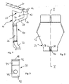
- FIG. 1 shows a pipe element 12 according to the invention, which is installed in a downpipe system 10 and is connected to a gutter 14 and a drainage pipe bend 16.
- the pipe element 12 according to the invention is in the exemplary embodiment a drain pipe.
- the downpipe system 10 is attached to a house wall 18 of a house, the house having a roof 20 at the outer end of which is the upwardly open gutter 14 runs.
- the drain pipe 12 introduces the collected rainwater from the gutter 14 funnel-shaped in the downpipe system 10 a.
- the drain pipe bend 16 which can be identified as a further pipe component, is attached to the drainage pipe 12.
- the drain pipe 12 and the drain pipe bend 16 are inserted into each other so that they partially overlap and between them a plug connection (at 24) is present.
- the drainage pipe bend 16 is arcuate and aligned so that it leads the rainwater in a fixed to the house wall 18, vertical downpipe 26.
- a straight intermediate pipe piece 28 and a further drain pipe bend 30 are arranged to bridge the distance between the drain pipe bend 16 and the vertical downpipe 26.
- the vertical downpipe 26 is followed by another downpipe bend 32, which transfers the rainwater into a lower region of the downpipe system 10.
- This lower area runs along the wall 18 perpendicular to the floor.
- the pipe element and the drain pipe 12 and the other pipe components, namely the gutter 14, the drain pipe bend 16, the straight pipe sections 26 and 28 and other drain pipes 30 and 32 are here made of stainless steel. But they can also be made of a copper alloy, another metal or a plastic material.
- Fig. 2 shows the discharge nozzle 12 according to the embodiment of the pipe element according to the invention.
- the discharge nozzle 12 has a plug-in end 34, which is designed here as a plug-in end, which is received in a plug-in end of the drainage pipe bend 16 when the discharge nozzle 12 and the discharge pipe bend 16 are put together.
- a plug-in end 34 is a radially inwardly extending and extending in the axial direction groove 36 is formed in which an elongated tongue formed as clamping element 38 by means of a Rivet 40 is attached.
- the plug-in end 34 may possibly have a conical shape and has an outer diameter which is smaller than the rest of the discharge nozzle 12.
- the groove 36 is provided at an arbitrary position on the circumference of the insertion end 34.
- Fig. 3 shows an enlarged front view of the elongate tongue 38. It has in a lower portion 42 a hole 44 through which a rivet for connecting the tongue can be inserted with the discharge nozzle.
- a double-angled upper portion 44 of the claw portion 46 is formed, which has a plurality of sharp-edged teeth 48 here. Due to the double angulation of the claw portion 46 and the teeth 48 are in the radial direction with respect to the insertion end 34 of the groove 36 before.
- These teeth 48 dig in the assembled state of the downcomer 12 with the drainage pipe bend 16 in the drainage pipe bend 16, wherein this Verkrallung when pulling the drain nozzle 12 and the drain pipe bend 16 is reinforced.
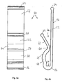
- FIGS. 4a and 4b A protective element 50 which can be pushed over the clamping element 38 or the tongue 38 and the insertion end 34 is shown in FIGS. 4a and 4b and in the assembled state in FIG.
- the protective element 50 is formed in the embodiment as a one-piece clip, wherein it has a substantially U-shaped form.
- the protective element 50 has a protective leg 52, a retaining leg 54 and a connecting portion 56 connecting these two legs 52, 54.
- the protective leg 52 and the retaining leg 54 are biased against each other by means of the connecting portion 56, so that they exert after putting the protective element 50 on the insertion end 34 with the attached clamping element 38 a clamping action on this.
- the protective element 50 is made in one piece and made of a plastic material, in particular polypropylene, as an injection-molded part.
- a plastic material in particular polypropylene
- Such a coating in particular achieved by immersing the tongue in a corresponding plastic material, is then removable, for example, during assembly of the drain neck 12 by means of mechanical action. Even by a trained as a protective cover the jamming of nested pipe socket can be prevented.
- the holding leg 54 has a section 58 concavely curved relative to the protective leg 52, to which a section 60 curved in a convex manner relative to the protective leg 52 adjoins.
- the convexly curved section 60 is adjoined by a substantially rectilinear end section 62 which, like the protective leg 52, has at its end a substantially circular terminal bead 64.
- the end portion 62 and the protection leg 52 are arranged in two intersecting planes so as to form a V-shaped insertion opening 66 which narrows toward the connection portion 56.
- the connecting portion 56 is arcuate and has an enlarged cross-sectional area in the region between the protective leg 52 and the retaining leg 54, which is indicated by a bulge 68 in Fig. 4b. It should also be noted that the connecting portion 56 and the concave portion 58, in which the greatest stresses when pushing apart of the two legs 52, 54 are present, have a substantially equal cross-sectional area, which with respect to the cross-sectional area of the protective leg 52 and the rectilinear End portion 62 is increased.
- the concave portion 58 receives, as shown in Fig. 5, on its side facing the protective leg 52 a rivet 70 form-fitting manner, whereby a secure hold of the protective element 50 at the insertion end 34 and the clamping element 38 is ensured.
- the protective leg 52 has a length that is approximately sized so that the protective leg may at least partially submerge upon substantial compression in the groove 36 formed in the male end 34. This ensures that the protective leg 52 protrudes only insignificantly beyond the defined outside of the groove portion circumference of the insertion end 34.
- the protective leg 52 has a width extending in the tangential direction relative to the insertion end 34, which corresponds at least to the width of the tongue 38, so that the clamping portion 46 and in particular the teeth 48 are completely covered by the protective leg 52.
- the facing away from the clamping element 38 surface 72 of the protective leg 52 provides when nesting of discharge nozzle 12 into each other a sliding surface, can abut the two downcomers to each other and are easily removed from each other, because between the sliding surface 72 and an adjacent part of another outlet nozzle a relatively low frictional force acts. Jamming is prevented due to the covered by the protective leg 52 clamping member 38 in any case.
- the clamping element in the form of an attached in a circumferential groove ring member having distributed over the circumference a plurality of radially outwardly projecting clamping portions
- three protective elements can be mounted according to the embodiment presented here. If these three protective elements are mounted approximately uniformly spaced from each other on the circumference of the male end, the stacking of such drainage nozzle each result in three contact surfaces, which are formed by the sliding surfaces of the three protective legs described above. In this way it can be ensured that each other stacked outlet nozzles only at these three surfaces but not at the non-protective covered portions of the annular clamping member engage each other clawing.
- the protective element 50 can be solved by simply widening and pulling the end portion 62 of the holding portion 54 and then removed from the drain pipe 12 after attachment of the drain nozzle 12 to the gutter 14.
- the clamping element is covered by the protective element 50, whereby the risk of injury to a user, in particular at the clamping portion 46 and the teeth 48, during transport, storage and assembly is reduced.
- the shaping also prevents injury to the protective element itself, as this no sharp edges, especially at ends, the be taken by a user.
- the shape described in detail in the embodiment of the protective element 50 may also be different as needed;
- the concave portion 58 could be substantially rectilinear or connected to the rectilinear end portion 62 as a generally convexly curved portion because no positive engagement with a rivet is necessary.
- a protective element can not necessarily be plugged from below over the insertion end and the clamping element, but that embodiments are also possible, which are plugged only over the radially projecting upper portion 44 of the tongue 38, as already above has been addressed with reference to a configured as a protective cover.
Landscapes
- Engineering & Computer Science (AREA)
- General Engineering & Computer Science (AREA)
- Mechanical Engineering (AREA)
- Architecture (AREA)
- Civil Engineering (AREA)
- Structural Engineering (AREA)
- Clamps And Clips (AREA)
- Emergency Protection Circuit Devices (AREA)
- Cable Accessories (AREA)
- Measuring Oxygen Concentration In Cells (AREA)
- Details Of Connecting Devices For Male And Female Coupling (AREA)
- Pipe Accessories (AREA)
- Quick-Acting Or Multi-Walled Pipe Joints (AREA)
- Ceramic Capacitors (AREA)
Abstract
Description
- Die vorliegende Erfindung betrifft ein Rohrelement als Rohrkomponente eines Stecksystems aus wenigstens zwei Rohrkomponenten zur Herstellung eines Leitungssystems, insbesondere als Teil eines Dachentwässerungssystems, wobei die Rohrkomponenten zur Herstellung einer Steckverbindung aneinander anschließbar sind und wobei das Rohrelement an einem Steckende eine insbesondere als Sicke ausgebildete Nut aufweist, in der ein der Sicherung der Steckverbindung dienendes Klemmelement, insbesondere aus Metall, angeordnet ist.
- Ein solches Rohrelement ist als Komponente eines in der anhängigen deutschen Patentanmeldung Nr.
10353660.4 bzw. in dereuropäischen Patentanmeldung 04025417.9 - Es hat sich bei der Verwendung von solchen Rohrelementen gezeigt, dass nach einem Ineinanderstapeln von solchen Rohrelementen, beispielsweise zur Lagerung bzw. zum Transport, das Herausnehmen der einzelnen Rohrelemente aus dem Stapel aufgrund der Klemmwirkung der Klemmelemente erschwert sein kann. Ferner kann bei unachtsamer Handhabung eines solchen Rohrelements eine Verletzungsgefahr am insbesondere scharfkantigen, ggf. verzahnten Klemmelement gegeben sein.
- Aufgabe der vorliegenden Erfindung ist es daher, ein Rohrelement bereitzustellen, welches sowohl eine verbesserte, montagefreundliche und insbesondere optisch unauffällige Steckverbindungssicherung zulässt, als auch Platz sparend gelagert bzw. transportiert werden kann, wobei das Verletzungsrisiko bei der Handhabung eines solchen Rohrelements verringert werden soll.
- Diese Aufgabe wird gemäß der technischen Lehre des Anspruchs 1 oder des Anspruchs 2 gelöst.
- Damit das Klemmelement beim Ineinanderstapeln von mehreren Rohrelementen seine Klemmwirkung nicht entfalten kann, weist das Klemmelement erfindungsgemäß ein vor Herstellung der Steckverbindung aus einer schützenden Position entfernbares Schutzelement auf. Mehrere Rohrelemente gemäß der Erfindung können somit bei am Klemmelement angebrachtem Schutzelement auf einfache Weise ineinander gestapelt werden und mit geringem Kraftaufwand wieder auseinander genommen werden, da durch das Schutzelement eine übermäßige Klemmwirkung bzw. Krallwirkung des Klemmelements zwischen zwei ineinander gestapelten Rohrelementen verhindert ist. Ferner schützt das Schutzelement einen das Rohrelement handhabenden Anwender vor Verletzungen am Klemmelement. Wird das Schutzelement entfernt, kann das Klemmelement des Rohrelements die andere Rohrkomponente bei Herstellung der Steckverbindung in der gewünschten Weise klemmend beaufschlagen.
- Zur verbesserten Steckverbindungssicherung kann das Steckende des Rohrelements als Einsteckende ausgebildet sein, das im Steckende der anderen Rohrkomponente aufnehmbar ist, wobei sich die insbesondere als Sicke ausgebildete Nut des Rohrelements nach radial innen erstreckt. Alternativ hierzu wird vorgeschlagen, dass das Steckende des Rohrelements eine Einstecköffnung aufweist, in dem das Steckende der anderen Rohrkomponente aufnehmbar ist, wobei sich die insbesondere als Sicke ausgebildete Nut des Rohrelements nach radial außen erstreckt.
- Um eine verbesserte Sicherung der Steckverbindung zu erreichen, kann das Klemmelement am Rohrelement formschlüssig fixiert, insbesondere angenietet sein. Hierdurch wird auch gewährleistet, dass das Klemmelement bei der Lagerung, beim Transport und der Endmontage nicht versehentlich vom Rohrelement entfernt wird.
- Besonders vorteilhaft ist es, wenn das Klemmelement wenigstens einen insbesondere scharfkantigen Krallabschnitt aufweist, mit dem es sich radial in Richtung aus der Nut des Rohrelements heraus erstreckt, derart, dass der Krallabschnitt mit der betreffenden anderen Rohrkomponente an dessen Steckende verkrallend in Eingriff kommen kann, um einer Trennbewegung der Rohrelemente relativ zueinander entgegenzuwirken. In diesem Zusammenhang wird ferner vorgeschlagen, dass der Krallabschnitt bei entferntem Schutzelement vor dem Zusammenstecken der Rohrkomponenten orthogonal zur Rohrelementachse oder schräg dazu in axialer Richtung weg von dem stirnseitigen Ende des die Nut mit dem darin aufgenommenen Klemmelement aufweisenden Steckendes des Rohrelementes orientiert ist, so dass er beim Zusammenstecken des Rohrelementes und der anderen Rohrkomponente von der anderen Rohrkomponente unter Aufrechterhaltung der gegenseitigen Beaufschlagung zwischen dem Krallabschnitt und der anderen Rohrkomponente zumindest teilweise in die Nut und dabei axial in Richtung weg von dem stirnseitigen Ende des die Nut aufweisenden Steckendes des einen Rohrelementes verdrängt werden kann.
- Für eine weiter verbesserte Klemmwirkung zur Sicherung der Steckverbindung kann der Krallabschnitt eine Verzahnung aufweisen, wobei die Zähne einer solchen Verzahnung mit der an dem Rohrelement anzubringenden anderen Rohrkomponente krallenartig bzw. hakenartig in Eingriff kommen.
- Das Klemmelement kann gemäß einer vorteilhaften Ausgestaltung des Rohrelements wenigstens eine Zunge mit dem Krallabschnitt an einem ihrer Enden aufweisen, wobei die Zunge insbesondere mehrfach abgewinkelt ist. Eine solche Zunge ist produktionstechnisch einfach herstellbar und durch die insbesondere mehrfache Abwinkelung kann die Steifheit des Klemmelements und somit die Stärke der Klemmwirkung beeinflusst werden.
- Alternativ hierzu wird vorgeschlagen, dass das Klemmelement als insbesondere unterbrochenes Ringelement ausgebildet ist, das in einer am Umfang des Rohrelements umlaufenden Nut aufgenommen ist.
- Bevorzugterweise ist das Rohrelement aus Metall, insbesondere Edelstahl oder einer Kupferlegierung gebildet. Das Klemmelement kann aus einem Stahl, insbesondere aus gehärtetem Stahl gebildet sein.
- In einer besonders vorteilhaften Ausführungsform der Erfindung ist das Rohrelement ein Ablaufstutzen zum Anbringen an einem Dachrinnenelement, wobei am Rohrelement die andere Rohrkomponente in Form eines Ablaufrohrbogens anzubringen ist.
- Das am Rohrelement angebrachte Schutzelement kann im Wesentlichen U-förmig ausgebildet sein, wobei es einen Schutzschenkel und einen Halteschenkel aufweist, welche über einen Verbindungsabschnitt miteinander verbunden sind. Vorzugsweise ist das Schutzelement einstückig, insbesondere als Clip, ausgebildet. Als Material für das Schutzelement kann ein Kunststoff, insbesondere Polypropylen, und/oder Kautschuk verwendet werden.
- Bevorzugterweise ist das Klemmelement zwischen dem Schutzschenkel und dem Halteschenkel angeordnet, wobei der Halteschenkel und der Schutzschenkel vermittels des Verbindungsabschnitts gegeneinander vorgespannt sind, so dass sie auf das Klemmelement eine Druckkraft ausüben, die zur Fixierung des Schutzelements am Rohrelement dient. Hierdurch wird erreicht, dass das Schutzelement bei der Lagerung bzw. beim Transport sicher am Rohrelement angebracht ist und im Normalfall nicht von diesem abfallen kann.
- Der Verbindungsabschnitt kann bogenförmig sein, und insbesondere in seinem bogenförmigen Krümmungsbereich eine wenigstens teilweise vergrößerte Querschnittsfläche aufweisen, um im Verbindungsabschnitt wirkende Biegespannungen aufnehmen zu können, die beim Voneinanderwegdrücken des Halteschenkels und des Schutzschenkels entgegen der Druckkraft entstehen. Der Schutzschenkei-verläuft vorzugsweise ausgehend vom Verbindungsabschnitt im Wesentlichen geradlinig, wodurch eine gute Stapelbarkeit der Rohrelemente mit angebrachtem Schutzelement gewährleistet ist, weil der geradlinige Schutzschenkel den Platzbedarf beim Stapeln von Rohrelementen kaum vergrößert.
- Der Halteschenkel kann mehrfach abgewinkelt sein und ausgehend vom Verbindungsabschnitt zuerst eine relativ zum Schutzschenkel im Wesentlichen konkave Krümmung und anschließend eine im Wesentlichen konvexe Krümmung aufweisen. Hierbei ist es bevorzugt, dass sich an die konvexe Krümmung ein im Wesentlichen geradliniger Endabschnitt des Halteschenkels anschließt.
- Durch die Ausbildung einer konkaven Krümmung kann der Halteschenkel in formschlüssige Anlage an einen Niet kommen, durch den das Klemmelement am Steckende des Rohrelements fixiert ist. Hierdurch kann das Abfallen des Schutzelements während der Lagerung bzw. dem Transport von Rohrelementen verhindert werden.
- Es ist ferner bevorzugt, dass der Endabschnitt des Halteschenkels und der im Wesentlichen geradlinige Schutzschenkel an ihren vom Verbindungsabschnitt entfernten Enden jeweils einen im Wesentlichen kreisförmigen Abschlusswulst aufweisen. Hierdurch kann das Aufsetzen des Schutzelements auf das Klemmelement bzw. das das Klemmelement aufweisende Steckende des Rohrelements vereinfacht werden. Ferner können die Abschlusswülste beim Entfernen des Schutzelements gefahrlos von einem Anwender ergriffen werden, da sie keine scharfen Kanten aufweisen.
- Der Endabschnitt des Halteschenkels und der Schutzschenkel können in zwei sich schneidenden Ebenen liegen, so dass sie eine Einführöffnung bilden, die sich zum Verbindungsabschnitt hin verengt und in die das Rohrelement eingeführt werden kann. Eine solche im Prinzip V-förmige Ausrichtung des Endabschnitts des Halteschenkels und des Schutzschenkels zueinander stellt eine relativ große Einführöffnung bereit, in die das Rohrelement einfach einführbar ist. Ferner bietet ein schräg abstehender Endabschnitt des Halteschenkels einen für einen Anwender ergreifbaren Abschnitt des Schutzelements, so dass das Schutzelement einfach vom Rohrelement entfernt werden kann, bevor das Rohrelement in Steckverbindung mit einer anderen Rohrkomponente gebracht wird.
- Im Folgenden werden die Vorteile der Erfindung anhand von Beispielen unter Bezugnahme auf die schematischen Zeichnungen beschrieben. Es zeigen:
- Fig. 1
- ein Anwendungsbeispiel eines erfindungsgemäßen Rohrelements in einem Leitungssystem als Regenfallrohrsystem an einem Haus,
- Fig. 2
- einen Ablaufstutzen als Ausführungsform des erfindungsgemäßen Rohrelements mit einer Zunge als Klemmelement,
- Fig. 3
- eine Frontansicht der Zunge gemäß dem Ausführungsbeispiel,
- Fig. 4a
- eine Frontansicht eines Schutzelements,
- Fig. 4b
- eine Seitenansicht des Schutzelements,
- Fig. 5
- einen Teilschnitt entlang der Linie V-V der Figur 2 des Ablaufstutzens mit daran angebrachtem Schutzelement.
- Die Figur 1 zeigt ein in einem Regenfallrohrsystem 10 eingebautes erfindungsgemäßes Rohrelement 12, welches mit einer Dachrinne 14 und einem Ablaufrohrbogen 16 verbunden ist. Das erfindungsgemäße Rohrelement 12 ist im Ausführungsbeispiel ein Ablaufstutzen. Das Regenfallrohrsystem 10 ist an einer Hauswand 18 eines Hauses angebracht, wobei das Haus ein Dach 20 aufweist, an dessen äußerem Ende die nach oben offene Dachrinne 14 verläuft. Der Ablaufstutzen 12 leitet das von der Dachrinne 14 gesammelte Regenwasser trichterförmig in das Regenfallrohrsystem 10 ein. Um den aufgrund eines Überstandes 22 von der Hauswand 18 beabstandeten oberen Bereich des Regenfallrohrsystems 10 an den nahe an der Hauswand 18 befestigten unteren Bereich des Regenfallsrohrsystems 10 heranzuführen, ist am Ablaufstutzen 12 der als weitere Rohrkomponente identifizierbare Ablaufrohrbogen 16 angebracht. Der Ablaufstutzen 12 und der Ablaufrohrbogen 16 sind ineinander gesteckt, so dass sie sich teilweise überlappen und zwischen ihnen eine Steckverbindung (bei 24) vorhanden ist. Der Ablaufrohrbogen 16 ist bogenförmig ausgestaltet und so ausgerichtet, dass er das Regenwasser in ein an der Hauswand 18 befestigtes, vertikales Fallrohr 26 führt. Zwischen dem Ablaufrohrbogen 16 und dem geraden, vertikalen Fallrohr 26 sind zur Überbrückung der Distanz zwischen dem Ablaufrohrbogen 16 und dem vertikalen Fallrohr 26 ein gerades Zwischenrohrstück 28 und ein weiterer Ablaufrohrbogen 30 angeordnet. In Abflussrichtung des Regenwassers schließt sich an das vertikale Fallrohr 26 ein weiterer Ablaufrohrbogen 32 an, der das Regenwasser in einen unteren Bereich des Regenfallrohrsystems 10 überführt. Dieser untere Bereich verläuft entlang der Hauswand 18 senkrecht in Richtung des Bodens. Das Rohrelement bzw. der Ablaufstutzen 12 sowie die anderen Rohrkomponenten, nämlich die Dachrinne 14, der Ablaufrohrbogen 16, die geraden Rohrstücke 26 und 28 sowie weitere Ablaufrohre 30 und 32, sind hier aus Edelstahl. Sie können aber ebenfalls aus einer Kupferlegierung, einem anderen Metall oder einem Kunststoffmaterial sein.
- Fig. 2 zeigt den Ablaufstutzen 12 gemäß der Ausführungsform des erfindungsgemäßen Rohrelements. An seinem in Abflussrichtung unteren Ende weist der Ablaufstutzen 12 ein Steckende 34 auf, welches hier als Einsteckende ausgebildet ist, das in einem Steckende des Ablaufrohrbogens 16 aufgenommen wird, wenn der Ablaufstutzen 12 und der Ablaufrohrbogen 16 zusammengesteckt werden. Im Einsteckende 34 ist eine sich nach radial innen erstreckende und in axialer Richtung verlaufende Nut 36 ausgebildet, in der ein als längliche Zunge ausgebildetes Klemmelement 38 vermittels einer Nietverbindung 40 befestigt ist. Das Steckende 34 kann ggf. konisch verlaufen und weist einen gegenüber dem übrigen Ablaufstutzen 12 verkleinerten äußeren Durchmesser auf. Die Nut 36 ist an einer beliebigen Stelle auf dem Umfang des Einsteckendes 34 vorgesehen.
- Fig. 3 zeigt eine vergrößerte Frontansicht der länglichen Zunge 38. Sie weist in einem unteren Bereich 42 ein Loch 44 auf, durch welches ein Niet zur Verbindung der Zunge mit dem Ablaufstutzen eingesteckt werden kann. In einem zweifach abgewinkelten oberen Bereich 44 ist der Krallabschnitt 46 ausgebildet, welcher hier mehrere scharfkantige Zähne 48 aufweist. Aufgrund der zweifachen Abwinkelung stehen der Krallabschnitt 46 bzw. die Zähne 48 in radialer Richtung bezogen auf das Einsteckende 34 aus der Nut 36 vor. Diese Zähne 48 verkrallen sich im zusammengesteckten Zustand des Ablaufstutzens 12 mit dem Ablaufrohrbogen 16 im Ablaufrohrbogen 16, wobei diese Verkrallung beim Auseinanderziehen des Ablaufstutzens 12 und des Ablaufrohrbogens 16 verstärkt wird.
- Diese verkrallende Wirkung des Klemmelements 38, insbesondere der Zunge 38, kann auch bei einem Ineinanderstapeln von mehreren Ablaufstutzen 12, beispielsweise zu Transport- und Lagerzwecken, auftreten, wodurch das Entfernen eines einzelnen Ablaufstutzens 12 aus einem solchen Stapel erschwert ist. Ein über das Klemmelement 38 bzw. die Zunge 38 und das Einsteckende 34 aufschiebbares Schutzelement 50 ist in den Figuren 4a und 4b sowie in montiertem Zustand in Fig. 5 dargestellt. Das Schutzelement 50 ist im Ausführungsbeispiel als einstückiger Clip ausgebildet, wobei es eine im Wesentlichen U-förmige Form aufweist. Das Schutzelement 50 weist einen Schutzschenkel 52, einen Halteschenkel 54 und einen diese beiden Schenkel 52, 54 verbindenden Verbindungsabschnitt 56 auf. Der Schutzschenkel 52 und der Halteschenkel 54 sind mittels des Verbindungsabschnitts 56 gegeneinander vorgespannt, so dass sie nach Aufsetzen des Schutzelements 50 auf das Einsteckende 34 mit dem daran angebrachten Klemmelement 38 eine Klemmwirkung auf diese ausüben.
- Zur Vereinfachung der Herstellung ist das Schutzelement 50 einstückig und aus einem Kunststoffmaterial, insbesondere Polypropylen, als Spritzgussteil ausgebildet. In diesem Zusammenhang wird darauf hingewiesen, dass es auch denkbar ist, ein solches Schutzelement als Überzug über den oberen Bereich 44 mit dem Klemmabschnitt 46 (vgl. Fig. 3) der Zunge 38 auszuführen. Ein solcher Überzug, insbesondere erreicht durch Eintauchen der Zunge in ein entsprechendes Kunststoffmaterial, ist dann beispielsweise bei der Montage des Ablaufstutzens 12 mittels mechanischer Einwirkung entfernbar. Auch durch ein als Überzug ausgebildetes Schutzelement kann das Verklemmen von ineinander gestapelten Rohrstutzen verhindert werden.
- In der Ausführungsform gemäß Fig. 4a und 4b weist der Halteschenkel 54 einen relativ zum Schutzschenkel 52 konkav gekrümmten Abschnitt 58 auf, an den sich ein relativ zum Schutzschenkel 52 konvex gekrümmter Abschnitt 60 anschließt. An den konvex gekrümmten Abschnitt 60 schließt sich ein im Wesentlichen geradliniger Endabschnitt 62 an, der wie der Schutzschenkel 52 an seinem Ende einen im Wesentlichen kreisförmigen Abschlusswulst 64 aufweist. Der Endabschnitt 62 und der Schutzschenkel 52 sind in zwei sich schneidenden Ebenen angeordnet, so dass sie eine V-förmige Einführöffnung 66 bilden, die sich zum Verbindungsabschnitt 56 hin verengt. Der Verbindungsabschnitt 56 ist bogenförmig ausgeführt und weist im Bereich zwischen dem Schutzschenkel 52 und dem Halteschenkel 54 eine vergrößerte Querschnittsfläche auf, was durch eine Ausbeulung 68 in Fig. 4b angedeutet ist. Es ist ferner darauf hinzuweisen, dass der Verbindungsabschnitt 56 und der konkave Abschnitt 58, in denen die größten Spannungen beim Auseinanderdrücken der beiden Schenkel 52, 54 vorhanden sind, eine im Wesentlichen gleich große Querschnittsfläche aufweisen, welche gegenüber der Querschnittsfläche des Schutzschenkels 52 und des geradlinigen Endabschnitts 62 vergrößert ist. Der konkav ausgebildete Abschnitt 58 nimmt, wie dies in Fig. 5 gezeigt ist, auf seiner dem Schutzschenkel 52 zugewandten Seite einen Niet 70 formschlüssig auf, wodurch ein sicherer Halt des Schutzelements 50 am Einsteckende 34 bzw. dem Klemmelement 38 gewährleistet ist.
- Unter Bezugnahme auf Fig. 5 wird darauf hingewiesen, dass der Schutzschenkel 52 eine Länge aufweist, die in etwa so bemessen ist, dass der Schutzschenkel bei starkem Zusammendrücken in die im Einsteckende 34 ausgebildete Nut 36 wenigstens teilweise eintauchen kann. Hierdurch wird erreicht, dass der Schutzschenkel 52 nur unwesentlich über den außerhalb des Nutbereichs definierten Umfang des Einsteckendes 34 hervorsteht.
- Es ist vorgesehen, dass der Schutzschenkel 52 eine sich in tangentialer Richtung bezogen auf das Einsteckende 34 erstreckende Breite aufweist, welche wenigstens der Breite der Zunge 38 entspricht, damit der Klemmabschnitt 46 und insbesondere die Zähne 48 vom Schutzschenkel 52 vollständig bedeckt sind. Die vom Klemmelement 38 abgewandte Oberfläche 72 des Schutzschenkels 52 bietet beim Ineinanderstapeln von Ablaufstutzen 12 ineinander eine Gleitfläche, an der zwei Ablaufstutzen aneinander anliegen können und leicht voneinander entfernbar sind, weil zwischen der Gleitfläche 72 und einem daran anliegenden Teil eines anderen Ablaufstutzens eine relativ geringe Reibkraft wirkt. Ein Verklemmen ist aufgrund des durch den Schutzschenkel 52 abgedeckten Klemmelements 38 auf jeden Fall verhindert.
- Im Hinblick auf eine nicht dargestellte Ausführungsform des Klemmelements in Form eines in einer umlaufenden Nut angebrachten Ringelements, das über den Umfang verteilt mehrere radial nach außen vorstehende Klemmabschnitte aufweist, sei darauf hingewiesen, dass zum Ineinanderstapeln von Ablaufstutzen mit einem solchen Klemmelement mehrere, insbesondere drei Schutzelemente gemäß der hier vorgestellten Ausführungsform angebracht werden können. Wenn diese drei Schutzelemente in etwa gleichmäßigem Abstand voneinander am Umfang des Steckendes angebracht sind, ergeben sich beim Ineinanderstapeln von solchen Ablaufstutzen jeweils drei Anlageflächen, welche von den oben beschriebenen Gleitflächen der drei Schutzschenkel gebildet werden. Hierdurch kann gewährleistet werden, dass ineinander gestapelte Ablaufstutzen nur an diesen drei Flächen aneinander anliegen, jedoch nicht an den nicht schützend abgedeckten Abschnitten des ringförmigen Klemmelements miteinander verkrallend in Eingriff kommen.
- Bei der Montage eines Ablaufstutzens 12 in einem Regenfallrohrsystem 10 kann nach Anbringung des Ablaufstutzens 12 an der Dachrinne 14 das Schutzelement 50 durch einfaches Aufweiten und Ziehen am Endabschnitt 62 des Halteabschnitts 54 gelöst und anschließend vom Ablaufstutzen 12 entfernt werden. Somit ist bis kurz vor der Herstellung einer Steckverbindung zwischen dem Ablaufstutzen 12 und einer weiteren Rohrkomponente, insbesondere dem Ablaufrohrbogen 16, das Klemmelement durch das Schutzelement 50 abgedeckt, wodurch die Verletzungsgefahr für einen Anwender, insbesondere am Klemmabschnitt 46 und den Zähnen 48, beim Transport, der Lagerung und der Montage verringert ist. Beim Entfernen des Schutzelements 50 sind auch die an den beiden Schenkeln 52, 54 ausgebildeten Abschlusswülste 64 hilfreich, weil sie das Ergreifen eines solchen Schenkels vereinfachen, wobei die Formgebung auch Verletzungen am Schutzelement selbst vorbeugt, da dieses keine scharfen Kanten, insbesondere an Enden, die von einem Anwender ergriffen werden, aufweist.
- Die in der Ausführungsform des Schutzelements 50 detailliert beschriebene Form kann je nach Bedarf auch anders sein; so könnte beispielsweise bei einer Zunge, welche durch eine Punktschweißung am Einsteckende 34 angebracht ist, der konkave Abschnitt 58 im Wesentlichen geradlinig oder, verbunden mit dem geradlinigen Endabschnitt 62, als insgesamt konvex gekrümmter Abschnitt ausgebildet sein, weil kein Formschluss mit einem Niet notwendig ist. Ferner wird auch darauf hingewiesen, dass ein solches Schutzelement nicht zwangsweise von unten über das Einsteckende und das Klemmelement aufgesteckt werden kann, sondern dass auch Ausführungsformen möglich sind, welche nur über den radial vorstehenden oberen Abschnitt 44 der Zunge 38 gesteckt sind, wie dies bereits oben unter Bezugnahme auf ein als Überzug ausgestaltetes Schutzelement angesprochen worden ist.
Claims (27)
- Rohrelement als Rohrkomponente eines Stecksystems aus wenigstens zwei Rohrkomponenten (12, 16) zur Herstellung eines Leitungssystems (10), insbesondere als Teil eines Dachentwässerungssystems, wobei die Rohrkomponenten (12, 16) zur Herstellung einer Steckverbindung (24) aneinander anschließbar sind und wobei das Rohrelement (12) an einem Steckende (34) eine insbesondere als Sicke ausgebildete Nut (36) aufweist, in der ein der Sicherung der Steckverbindung dienendes Klemmelement (38), insbesondere aus Metall, angeordnet ist, wobei das Klemmelement (38) ein vor Herstellung der Steckverbindung aus einer schützenden Position entfernbares Schutzelement (50) aufweist, so dass das Klemmelement (38) nach Entfernung des Schutzelementes (50) die andere Rohrkomponente (16) bei Herstellung der Steckverbindung klemmend beaufschlagen kann.
- Rohrelement als Rohrkomponente eines Stecksystems aus wenigstens zwei Rohrkomponenten (12, 16) zur Herstellung eines Leitungssystems (10), insbesondere als Teil eines Dachentwässerungssystems, wobei die Rohrkomponenten (12, 16) zur Herstellung einer Steckverbindung (24) aneinander anschließbar sind und wobei an einem Steckende (34) des Rohrelementes (12) ein der Sicherung der Steckverbindung dienendes Klemmelement (38), insbesondere aus Metall, angeordnet ist, wobei das Klemmelement (38) einen vor Herstellung der Steckverbindung zumindest teilweise zerstörbaren Schutzüberzug insbesondere aus Kunststoff aufweist, so dass das Klemmelement (38) nach Zerstörung des Schutzüberzugs die andere Rohrkomponente (16) bei Herstellung der Steckverbindung klemmend beaufschlagen kann.
- Rohrelement nach Anspruch 2, wobei das Klemmelement (38) in einer insbesondere als Sicke ausgebildeten Nut (36) angeordnet ist.
- Rohrelement nach Anspruch 2 oder 3, wobei der Schutzüberzug durch Eintauchen, Anstreichen oder Spritzen des Klemmelementes (38) in bzw. mit nachträglich aushärtendem flüssigem Kunststoff hergestellt ist.
- Rohrelement nach einem der vorhergehenden Ansprüche, dadurch gekennzeichnet, dass das Steckende (34) des Rohrelements (12) als Einsteckende (34) ausgebildet ist, das im Steckende der anderen Rohrkomponente (16) aufnehmbar ist, wobei sich die insbesondere als Sicke ausgebildete Nut (36) des Rohrelements (12) nach radial innen erstreckt.
- Rohrelement nach einem der Ansprüche 1 bis 4, dadurch gekennzeichnet, dass das Steckende des Rohrelements eine Einstecköffnung aufweist, in dem das Steckende der anderen Rohrkomponente aufnehmbar ist, wobei sich die insbesondere als Sicke ausgebildete Nut des Rohrelements nach radial außen erstreckt.
- Rohrelement nach einem der Ansprüche 1 bis 6, dadurch gekennzeichnet, dass das Klemmelement (38) am Rohrelement (12) formschlüssig fixiert, insbesondere angenietet ist.
- Rohrelement nach einem der Ansprüche 1 bis 7, dadurch gekennzeichnet, dass das Klemmelement (38) wenigstens einen insbesondere scharfkantigen Krallabschnitt (46) aufweist, mit dem es sich radial in Richtung aus der Nut (36) des Rohrelements (12) heraus erstreckt, derart, dass der Krallabschnitt (46) mit der betreffenden anderen Rohrkomponente (16) an dessen Steckende verkrallend in Eingriff kommen kann, um einer Trennbewegung der Rohrelemente (12, 16) relativ zueinander entgegenzuwirken.
- Rohrelement nach Anspruch 8, dadurch gekennzeichnet, dass der Krallabschnitt (46) bei entferntem Schutzelement (50) vor dem Zusammenstecken der Rohrkomponenten (12, 16) orthogonal zur Rohrelementachse oder schräg dazu in axialer Richtung weg von dem stirnseitigen Ende des die Nut (36) mit dem darin aufgenommenen Klemmelement (38) aufweisenden Steckendes des Rohrelementes (12) orientiert ist, so dass er beim Zusammenstecken des Rohrelementes (12) und der anderen Rohrkomponente (16) von der anderen Rohrkomponente (16) unter Aufrechterhaltung der gegenseitigen Beaufschlagung zwischen dem Krallabschnitt (46) und der anderen Rohrkomponente (16) zumindest teilweise in die Nut (36) und dabei axial in Richtung weg von dem stirnseitigen Ende des die Nut (36) aufweisenden Steckendes (34) des Rohrelementes (12) verdrängt werden kann.
- Rohrelement nach einem der Ansprüche 8 oder 9, dadurch gekennzeichnet, dass der Krallabschnitt (46) verzahnt ist.
- Rohrelement nach einem der Ansprüche 8 bis 10, dadurch gekennzeichnet, dass das Klemmelement wenigstens eine Zunge (38) mit dem Krallabschnitt (46) an einem ihrer Enden aufweist, wobei die Zunge (38) insbesondere mehrfach abgewinkelt ist.
- Rohrelement nach einem der Ansprüche 1 bis 10, dadurch gekennzeichnet, dass das Klemmelement als insbesondere unterbrochenes Ringelement ausgebildet ist, das in einer am Umfang des Rohrelementes umlaufenden Nut aufgenommen ist.
- Rohrelement nach einem der vorhergehenden Ansprüche, dadurch gekennzeichnet, dass das Rohrelement (12) aus Metall, insbesondere Edelstahl oder einer Kupferlegierung, gebildet ist.
- Rohrelement nach einem der vorhergehenden Ansprüche, dadurch gekennzeichnet, dass das Klemmelement (38) aus einem Stahl, insbesondere aus gehärtetem Stahl, gebildet ist.
- Rohrelement nach einem der vorhergehenden Ansprüche, dadurch gekennzeichnet, dass das Rohrelement ein Ablaufstutzen (12) zum Anbringen an einem Dachrinnenelement (14) ist, wobei am Rohrelement die andere Rohrkomponente in Form eines Ablaufrohrbogens (16) anzubringen ist.
- Rohrelement nach Anspruch 1 oder einem der darauf rückbezogenen Ansprüche, dadurch gekennzeichnet, dass das Schutzelement (50) im Wesentlichen U-förmig ausgebildet ist, wobei es einen Schutzschenkel (52) und einen Halteschenkel (54) aufweist, welche über einen Verbindungsabschnitt (56) miteinander verbunden sind.
- Rohrelement nach Anspruch 16, dadurch gekennzeichnet, dass das Schutzelement (50) einstückig ausgebildet ist und aus Kunststoff, insbesondere Polypropylen, und/oder Kautschuk gebildet ist.
- Rohrelement nach Anspruch 16 oder 17, dadurch gekennzeichnet, dass das Klemmelement (38) zwischen dem Schutzschenkel (52) und dem Halteschenkel (54) angeordnet ist.
- Rohrelement nach Anspruch 18, dadurch gekennzeichnet, dass der Halteschenkel (54) und der Schutzschenkel (52) vermittels des Verbindungsabschnitts (56) gegeneinander vorgespannt sind, so dass sie auf das Klemmelement (38) eine Druckkraft ausüben, die zur Fixierung des Schutzelements (50) am Rohrelement (12) dient.
- Rohrelement nach Anspruch 19, dadurch gekennzeichnet, dass der Verbindungsabschnitt (56) bogenförmig ist und insbesondere in seinem bogenförmigen Krümmungsbereich eine wenigstens teilweise vergrößerte Querschnittsfläche aufweist, um im Verbindungsabschnitt (56) wirkende Biegespannungen aufnehmen zu können, die beim voneinander Wegdrücken des Halteschenkels (54) und des Schutzschenkels (52) entgegen der Druckkraft entstehen.
- Rohrelement nach einem der Ansprüche 16 bis 20, dadurch gekennzeichnet, dass der Schutzschenkel (52) ausgehend vom Verbindungsabschnitt (56) im Wesentlichen geradlinig verläuft.
- Rohrelement nach einem der Ansprüche 16 bis 21, dadurch gekennzeichnet, dass der Halteschenkel (54) mehrfach abgewinkelt ist.
- Rohrelement nach Anspruch 22, dadurch gekennzeichnet, dass der Halteschenkel (54) ausgehend vom Verbindungsabschnitt (56) zuerst eine relativ zum Schutzschenkel (52) im Wesentlichen konkave Krümmung (58) und anschließend eine im Wesentlichen konvexe Krümmung (60) aufweist.
- Rohrelement nach Anspruch 23, dadurch gekennzeichnet, dass der Halteschenkel (54) einen an die konvexe Krümmung (60) anschließenden, im Wesentlichen geradlinigen Endabschnitt (62) aufweist.
- Rohrelement nach Anspruch 23 oder 24, jedenfalls nach Anspruch 7, dadurch gekennzeichnet, dass die konkave Krümmung (58) eine formschlüssige Anlage des Halteschenkels (54) an einem Niet (70) ermöglicht, durch den das Klemmelement (38) am Steckende (34) des Rohrelements (12) fixiert ist.
- Rohrelement nach einem der Ansprüche 16 bis 25, jedenfalls nach Anspruch 16 und 24, dadurch gekennzeichnet, dass der Endabschnitt (62) des Halteschenkels (54) und der Schutzschenkel (52) an ihren vom Verbindungsabschnitt (56) entfernten Enden jeweils einen im Wesentlichen kreisförmigen Abschlusswulst (64) aufweisen.
- Rohrelement nach einem der Ansprüche 17 bis 26, jedenfalls nach Anspruch 17 und 25, dadurch gekennzeichnet, dass der Endabschnitt (62) des Halteschenkels (54) und der Schutzschenkel (52) in zwei sich schneidenden Ebenen liegen, so dass sie eine Einführöffnung (66) bilden, die sich zum Verbindungsabschnitt (56) hin verengt und in die das Rohrelement (12) eingeführt werden kann.
Priority Applications (2)
| Application Number | Priority Date | Filing Date | Title |
|---|---|---|---|
| SI200630967T SI1722145T1 (sl) | 2005-05-13 | 2006-03-27 | Cevni element z zaščitnim elementom |
| PL06006246T PL1722145T3 (pl) | 2005-05-13 | 2006-03-27 | Element rurowy z elementem ochronnym |
Applications Claiming Priority (1)
| Application Number | Priority Date | Filing Date | Title |
|---|---|---|---|
| DE202005009503U DE202005009503U1 (de) | 2005-05-13 | 2005-05-13 | Rohrelement mit Schutzelement |
Publications (3)
| Publication Number | Publication Date |
|---|---|
| EP1722145A2 true EP1722145A2 (de) | 2006-11-15 |
| EP1722145A3 EP1722145A3 (de) | 2010-03-17 |
| EP1722145B1 EP1722145B1 (de) | 2011-01-05 |
Family
ID=36698647
Family Applications (1)
| Application Number | Title | Priority Date | Filing Date |
|---|---|---|---|
| EP06006246A Not-in-force EP1722145B1 (de) | 2005-05-13 | 2006-03-27 | Rohrelement mit Schutzelement |
Country Status (5)
| Country | Link |
|---|---|
| EP (1) | EP1722145B1 (de) |
| AT (1) | ATE494506T1 (de) |
| DE (2) | DE202005009503U1 (de) |
| PL (1) | PL1722145T3 (de) |
| SI (1) | SI1722145T1 (de) |
Cited By (2)
| Publication number | Priority date | Publication date | Assignee | Title |
|---|---|---|---|---|
| FR2928159A1 (fr) * | 2008-02-29 | 2009-09-04 | Fldh Soc Par Actions Simplifie | Element tubulaire de raccordement et dispositif d'evacuation comprenant un tel element |
| EP3524749A1 (de) * | 2018-02-09 | 2019-08-14 | Metallwarenfabrik Marktoberdorf GmbH & Co. KG | Klemmfeder zur verbindung von entwässerungskomponenten, insbesondere dachentwässerungskomponenten |
Citations (2)
| Publication number | Priority date | Publication date | Assignee | Title |
|---|---|---|---|---|
| GB191005290A (en) * | 1910-03-02 | 1910-06-30 | Reginald Haddan | Improvements in Protectors for the Threaded Ends of Pipes, Tubing, Rods and the like. |
| EP1531208A2 (de) * | 2003-11-17 | 2005-05-18 | Metallwarenfabrik Marktoberdorf GmbH & Co. KG | Leitungssystem zum Ableiten von Flüssigkeit |
Family Cites Families (9)
| Publication number | Priority date | Publication date | Assignee | Title |
|---|---|---|---|---|
| DE7201172U (de) * | 1972-06-22 | Omark Industries Inc | Einrichtung zum Anbringen eines Schutz Überzugs auf den Schneidgliedern einer Sägekette | |
| US1686254A (en) * | 1927-01-19 | 1928-10-02 | Rachlin Max | Sheet-metal pipe coupling |
| US2212679A (en) * | 1937-09-27 | 1940-08-27 | Hoover Co | Dusting tool for suction cleaners |
| DE3602658C2 (de) * | 1986-01-29 | 1994-09-08 | Franz Zambelli | Dachrinnenablaufstutzen |
| IT234443Y1 (it) * | 1994-06-22 | 2000-03-09 | Armando Roberto | Utensile per provocare l'arricciolamento di nastri ornamentali ad ad esempio per la confezione di pacchi. |
| EP0797038A1 (de) * | 1996-03-20 | 1997-09-24 | Climovent System s.a.s. di Franco Guazzone e C | Rohrfitting, speziell für Lüftungssysteme |
| US6341804B1 (en) * | 1998-11-20 | 2002-01-29 | Tosetz Co., Ltd | Slip-out preventive unit of supply exhaust pipe |
| DE20013515U1 (de) * | 2000-08-05 | 2000-10-19 | Rheinzink Gmbh | Anschluß für einen Dachrinnenentwässerungsstrang an eine Dachrinne an einem Dachüberstand und Bau-Set dazu |
| DE10160194A1 (de) * | 2001-12-09 | 2003-06-18 | Zambelli Fertigungs Gmbh | Montagehilfe für Regenwasser-Ablaufgarnituren |
-
2005
- 2005-05-13 DE DE202005009503U patent/DE202005009503U1/de not_active Expired - Lifetime
-
2006
- 2006-03-27 AT AT06006246T patent/ATE494506T1/de active
- 2006-03-27 DE DE502006008640T patent/DE502006008640D1/de active Active
- 2006-03-27 EP EP06006246A patent/EP1722145B1/de not_active Not-in-force
- 2006-03-27 PL PL06006246T patent/PL1722145T3/pl unknown
- 2006-03-27 SI SI200630967T patent/SI1722145T1/sl unknown
Patent Citations (2)
| Publication number | Priority date | Publication date | Assignee | Title |
|---|---|---|---|---|
| GB191005290A (en) * | 1910-03-02 | 1910-06-30 | Reginald Haddan | Improvements in Protectors for the Threaded Ends of Pipes, Tubing, Rods and the like. |
| EP1531208A2 (de) * | 2003-11-17 | 2005-05-18 | Metallwarenfabrik Marktoberdorf GmbH & Co. KG | Leitungssystem zum Ableiten von Flüssigkeit |
Cited By (2)
| Publication number | Priority date | Publication date | Assignee | Title |
|---|---|---|---|---|
| FR2928159A1 (fr) * | 2008-02-29 | 2009-09-04 | Fldh Soc Par Actions Simplifie | Element tubulaire de raccordement et dispositif d'evacuation comprenant un tel element |
| EP3524749A1 (de) * | 2018-02-09 | 2019-08-14 | Metallwarenfabrik Marktoberdorf GmbH & Co. KG | Klemmfeder zur verbindung von entwässerungskomponenten, insbesondere dachentwässerungskomponenten |
Also Published As
| Publication number | Publication date |
|---|---|
| EP1722145B1 (de) | 2011-01-05 |
| ATE494506T1 (de) | 2011-01-15 |
| PL1722145T3 (pl) | 2011-06-30 |
| EP1722145A3 (de) | 2010-03-17 |
| SI1722145T1 (sl) | 2011-05-31 |
| DE202005009503U1 (de) | 2006-09-28 |
| DE502006008640D1 (de) | 2011-02-17 |
Similar Documents
| Publication | Publication Date | Title |
|---|---|---|
| DE3424675C2 (de) | Schlauchkupplung | |
| DE4240136C1 (de) | ||
| DE3933589C2 (de) | ||
| DE3815168C2 (de) | ||
| DE19828059C2 (de) | Anschlußarmatur mit einem durch Schlitze in Haltezungen aufgeteilten Befestigungsvorsprung | |
| EP1228331B1 (de) | Anschlussarmatur für umfangsgerippte längliche körper mit einem einrastenden haltevorsprung | |
| EP0750152A1 (de) | Steckverbindung für den Anschluss von Rohr- und Schlauchleitungen | |
| DE19503722A1 (de) | Schlauchanschluß, insbesondere zum Anschluß von Schläuchen, wie Gartenschläuchen | |
| EP2082101B1 (de) | Rinne | |
| EP2497991B1 (de) | Verbindungsanordnung | |
| DE102014108563B3 (de) | Abgasrohr, Abgasrohrsystem sowie Montageverfahren | |
| EP0549860A1 (de) | Vorrichtung zum gegenseitigen Verbinden von zwei Leitungen, insbesondere Kraftstoffleitungen | |
| EP1722145B1 (de) | Rohrelement mit Schutzelement | |
| DE3705610A1 (de) | Loesbare steckverbindung fuer rohrleitungen | |
| EP2584237B1 (de) | Vorrichtung zum Festlegen einer Rohreinheit | |
| DE19834003A1 (de) | Montagehilfe für eine Befestigungsvorrichtung, insbesondere für Schlauch- oder Rohranschlüsse | |
| EP2568207A1 (de) | Rohrverbinder | |
| DE102004032053B4 (de) | Rohrschelle mit integriertem Rast-Verschluss | |
| DE2063463A1 (de) | Rohrverbindungsstuck zum Anschließen von Abzweigrohren an ein Hauptrohr | |
| EP0446594A1 (de) | Zugfester zweiteiliger Druckknopfverschluss | |
| DE19905809A1 (de) | Anschlußverbindung und Anschlußelement für ringgewellte Schlauchleitungen | |
| DE19748623A1 (de) | Preßverbindung | |
| DE10335530A1 (de) | Rohrverbindung | |
| DE4329650C2 (de) | Schlauchfassung | |
| DE102013104041B4 (de) | Spanneinrichtung für eine Abgasrohreinheit einer Heizungsanlage, Einheit mit einer Spanneinrichtung und Abgasrohrsystem |
Legal Events
| Date | Code | Title | Description |
|---|---|---|---|
| PUAI | Public reference made under article 153(3) epc to a published international application that has entered the european phase |
Free format text: ORIGINAL CODE: 0009012 |
|
| AK | Designated contracting states |
Kind code of ref document: A2 Designated state(s): AT BE BG CH CY CZ DE DK EE ES FI FR GB GR HU IE IS IT LI LT LU LV MC NL PL PT RO SE SI SK TR |
|
| AX | Request for extension of the european patent |
Extension state: AL BA HR MK YU |
|
| PUAL | Search report despatched |
Free format text: ORIGINAL CODE: 0009013 |
|
| AK | Designated contracting states |
Kind code of ref document: A3 Designated state(s): AT BE BG CH CY CZ DE DK EE ES FI FR GB GR HU IE IS IT LI LT LU LV MC NL PL PT RO SE SI SK TR |
|
| AX | Request for extension of the european patent |
Extension state: AL BA HR MK YU |
|
| 17P | Request for examination filed |
Effective date: 20100317 |
|
| GRAP | Despatch of communication of intention to grant a patent |
Free format text: ORIGINAL CODE: EPIDOSNIGR1 |
|
| GRAS | Grant fee paid |
Free format text: ORIGINAL CODE: EPIDOSNIGR3 |
|
| AKX | Designation fees paid |
Designated state(s): AT BE BG CH CY CZ DE DK EE ES FI FR GB GR HU IE IS IT LI LT LU LV MC NL PL PT RO SE SI SK TR |
|
| GRAA | (expected) grant |
Free format text: ORIGINAL CODE: 0009210 |
|
| AK | Designated contracting states |
Kind code of ref document: B1 Designated state(s): AT BE BG CH CY CZ DE DK EE ES FI FR GB GR HU IE IS IT LI LT LU LV MC NL PL PT RO SE SI SK TR |
|
| REG | Reference to a national code |
Ref country code: GB Ref legal event code: FG4D Free format text: NOT ENGLISH |
|
| REG | Reference to a national code |
Ref country code: CH Ref legal event code: EP Ref country code: CH Ref legal event code: NV Representative=s name: BOHEST AG |
|
| REG | Reference to a national code |
Ref country code: IE Ref legal event code: FG4D Free format text: LANGUAGE OF EP DOCUMENT: GERMAN |
|
| REF | Corresponds to: |
Ref document number: 502006008640 Country of ref document: DE Date of ref document: 20110217 Kind code of ref document: P |
|
| REG | Reference to a national code |
Ref country code: DE Ref legal event code: R096 Ref document number: 502006008640 Country of ref document: DE Effective date: 20110217 |
|
| REG | Reference to a national code |
Ref country code: SK Ref legal event code: T3 Ref document number: E 8825 Country of ref document: SK |
|
| REG | Reference to a national code |
Ref country code: NL Ref legal event code: VDEP Effective date: 20110105 |
|
| LTIE | Lt: invalidation of european patent or patent extension |
Effective date: 20110105 |
|
| REG | Reference to a national code |
Ref country code: PL Ref legal event code: T3 |
|
| PG25 | Lapsed in a contracting state [announced via postgrant information from national office to epo] |
Ref country code: PT Free format text: LAPSE BECAUSE OF FAILURE TO SUBMIT A TRANSLATION OF THE DESCRIPTION OR TO PAY THE FEE WITHIN THE PRESCRIBED TIME-LIMIT Effective date: 20110505 Ref country code: LV Free format text: LAPSE BECAUSE OF FAILURE TO SUBMIT A TRANSLATION OF THE DESCRIPTION OR TO PAY THE FEE WITHIN THE PRESCRIBED TIME-LIMIT Effective date: 20110105 Ref country code: GR Free format text: LAPSE BECAUSE OF FAILURE TO SUBMIT A TRANSLATION OF THE DESCRIPTION OR TO PAY THE FEE WITHIN THE PRESCRIBED TIME-LIMIT Effective date: 20110406 Ref country code: LT Free format text: LAPSE BECAUSE OF FAILURE TO SUBMIT A TRANSLATION OF THE DESCRIPTION OR TO PAY THE FEE WITHIN THE PRESCRIBED TIME-LIMIT Effective date: 20110105 Ref country code: IS Free format text: LAPSE BECAUSE OF FAILURE TO SUBMIT A TRANSLATION OF THE DESCRIPTION OR TO PAY THE FEE WITHIN THE PRESCRIBED TIME-LIMIT Effective date: 20110505 Ref country code: SE Free format text: LAPSE BECAUSE OF FAILURE TO SUBMIT A TRANSLATION OF THE DESCRIPTION OR TO PAY THE FEE WITHIN THE PRESCRIBED TIME-LIMIT Effective date: 20110105 Ref country code: ES Free format text: LAPSE BECAUSE OF FAILURE TO SUBMIT A TRANSLATION OF THE DESCRIPTION OR TO PAY THE FEE WITHIN THE PRESCRIBED TIME-LIMIT Effective date: 20110416 |
|
| REG | Reference to a national code |
Ref country code: IE Ref legal event code: FD4D |
|
| PG25 | Lapsed in a contracting state [announced via postgrant information from national office to epo] |
Ref country code: CY Free format text: LAPSE BECAUSE OF FAILURE TO SUBMIT A TRANSLATION OF THE DESCRIPTION OR TO PAY THE FEE WITHIN THE PRESCRIBED TIME-LIMIT Effective date: 20110105 Ref country code: BG Free format text: LAPSE BECAUSE OF FAILURE TO SUBMIT A TRANSLATION OF THE DESCRIPTION OR TO PAY THE FEE WITHIN THE PRESCRIBED TIME-LIMIT Effective date: 20110405 Ref country code: FI Free format text: LAPSE BECAUSE OF FAILURE TO SUBMIT A TRANSLATION OF THE DESCRIPTION OR TO PAY THE FEE WITHIN THE PRESCRIBED TIME-LIMIT Effective date: 20110105 Ref country code: NL Free format text: LAPSE BECAUSE OF FAILURE TO SUBMIT A TRANSLATION OF THE DESCRIPTION OR TO PAY THE FEE WITHIN THE PRESCRIBED TIME-LIMIT Effective date: 20110105 |
|
| PG25 | Lapsed in a contracting state [announced via postgrant information from national office to epo] |
Ref country code: IE Free format text: LAPSE BECAUSE OF FAILURE TO SUBMIT A TRANSLATION OF THE DESCRIPTION OR TO PAY THE FEE WITHIN THE PRESCRIBED TIME-LIMIT Effective date: 20110105 Ref country code: EE Free format text: LAPSE BECAUSE OF FAILURE TO SUBMIT A TRANSLATION OF THE DESCRIPTION OR TO PAY THE FEE WITHIN THE PRESCRIBED TIME-LIMIT Effective date: 20110105 Ref country code: MC Free format text: LAPSE BECAUSE OF NON-PAYMENT OF DUE FEES Effective date: 20110331 Ref country code: DK Free format text: LAPSE BECAUSE OF FAILURE TO SUBMIT A TRANSLATION OF THE DESCRIPTION OR TO PAY THE FEE WITHIN THE PRESCRIBED TIME-LIMIT Effective date: 20110105 |
|
| PLBE | No opposition filed within time limit |
Free format text: ORIGINAL CODE: 0009261 |
|
| STAA | Information on the status of an ep patent application or granted ep patent |
Free format text: STATUS: NO OPPOSITION FILED WITHIN TIME LIMIT |
|
| PG25 | Lapsed in a contracting state [announced via postgrant information from national office to epo] |
Ref country code: RO Free format text: LAPSE BECAUSE OF FAILURE TO SUBMIT A TRANSLATION OF THE DESCRIPTION OR TO PAY THE FEE WITHIN THE PRESCRIBED TIME-LIMIT Effective date: 20110105 |
|
| 26N | No opposition filed |
Effective date: 20111006 |
|
| GBPC | Gb: european patent ceased through non-payment of renewal fee |
Effective date: 20110405 |
|
| REG | Reference to a national code |
Ref country code: DE Ref legal event code: R097 Ref document number: 502006008640 Country of ref document: DE Effective date: 20111006 |
|
| PG25 | Lapsed in a contracting state [announced via postgrant information from national office to epo] |
Ref country code: GB Free format text: LAPSE BECAUSE OF NON-PAYMENT OF DUE FEES Effective date: 20110405 |
|
| PGFP | Annual fee paid to national office [announced via postgrant information from national office to epo] |
Ref country code: IT Payment date: 20120326 Year of fee payment: 7 |
|
| PGFP | Annual fee paid to national office [announced via postgrant information from national office to epo] |
Ref country code: DE Payment date: 20130115 Year of fee payment: 8 Ref country code: CH Payment date: 20130322 Year of fee payment: 8 Ref country code: CZ Payment date: 20130321 Year of fee payment: 8 Ref country code: FR Payment date: 20130408 Year of fee payment: 8 Ref country code: LU Payment date: 20130328 Year of fee payment: 8 |
|
| PGFP | Annual fee paid to national office [announced via postgrant information from national office to epo] |
Ref country code: PL Payment date: 20130225 Year of fee payment: 8 Ref country code: SI Payment date: 20130228 Year of fee payment: 8 |
|
| PGFP | Annual fee paid to national office [announced via postgrant information from national office to epo] |
Ref country code: AT Payment date: 20130313 Year of fee payment: 8 |
|
| PGFP | Annual fee paid to national office [announced via postgrant information from national office to epo] |
Ref country code: BE Payment date: 20130320 Year of fee payment: 8 |
|
| PG25 | Lapsed in a contracting state [announced via postgrant information from national office to epo] |
Ref country code: TR Free format text: LAPSE BECAUSE OF FAILURE TO SUBMIT A TRANSLATION OF THE DESCRIPTION OR TO PAY THE FEE WITHIN THE PRESCRIBED TIME-LIMIT Effective date: 20110105 |
|
| PG25 | Lapsed in a contracting state [announced via postgrant information from national office to epo] |
Ref country code: HU Free format text: LAPSE BECAUSE OF FAILURE TO SUBMIT A TRANSLATION OF THE DESCRIPTION OR TO PAY THE FEE WITHIN THE PRESCRIBED TIME-LIMIT Effective date: 20110105 |
|
| PGFP | Annual fee paid to national office [announced via postgrant information from national office to epo] |
Ref country code: SK Payment date: 20130816 Year of fee payment: 8 |
|
| REG | Reference to a national code |
Ref country code: CH Ref legal event code: PCAR Free format text: NEW ADDRESS: HOLBEINSTRASSE 36-38, 4051 BASEL (CH) |
|
| REG | Reference to a national code |
Ref country code: DE Ref legal event code: R119 Ref document number: 502006008640 Country of ref document: DE |
|
| PG25 | Lapsed in a contracting state [announced via postgrant information from national office to epo] |
Ref country code: LU Free format text: LAPSE BECAUSE OF NON-PAYMENT OF DUE FEES Effective date: 20140327 Ref country code: CZ Free format text: LAPSE BECAUSE OF NON-PAYMENT OF DUE FEES Effective date: 20140327 |
|
| REG | Reference to a national code |
Ref country code: CH Ref legal event code: PL |
|
| REG | Reference to a national code |
Ref country code: AT Ref legal event code: MM01 Ref document number: 494506 Country of ref document: AT Kind code of ref document: T Effective date: 20140327 |
|
| REG | Reference to a national code |
Ref country code: SK Ref legal event code: MM4A Ref document number: E 8825 Country of ref document: SK Effective date: 20140327 |
|
| REG | Reference to a national code |
Ref country code: FR Ref legal event code: ST Effective date: 20141128 |
|
| REG | Reference to a national code |
Ref country code: SI Ref legal event code: KO00 Effective date: 20141104 |
|
| REG | Reference to a national code |
Ref country code: DE Ref legal event code: R119 Ref document number: 502006008640 Country of ref document: DE Effective date: 20141001 |
|
| PG25 | Lapsed in a contracting state [announced via postgrant information from national office to epo] |
Ref country code: SK Free format text: LAPSE BECAUSE OF NON-PAYMENT OF DUE FEES Effective date: 20140327 Ref country code: DE Free format text: LAPSE BECAUSE OF NON-PAYMENT OF DUE FEES Effective date: 20141001 Ref country code: FR Free format text: LAPSE BECAUSE OF NON-PAYMENT OF DUE FEES Effective date: 20140331 Ref country code: CH Free format text: LAPSE BECAUSE OF NON-PAYMENT OF DUE FEES Effective date: 20140331 Ref country code: LI Free format text: LAPSE BECAUSE OF NON-PAYMENT OF DUE FEES Effective date: 20140331 |
|
| PG25 | Lapsed in a contracting state [announced via postgrant information from national office to epo] |
Ref country code: SI Free format text: LAPSE BECAUSE OF NON-PAYMENT OF DUE FEES Effective date: 20140328 Ref country code: AT Free format text: LAPSE BECAUSE OF NON-PAYMENT OF DUE FEES Effective date: 20140327 |
|
| PG25 | Lapsed in a contracting state [announced via postgrant information from national office to epo] |
Ref country code: IT Free format text: LAPSE BECAUSE OF NON-PAYMENT OF DUE FEES Effective date: 20140327 |
|
| PG25 | Lapsed in a contracting state [announced via postgrant information from national office to epo] |
Ref country code: PL Free format text: LAPSE BECAUSE OF NON-PAYMENT OF DUE FEES Effective date: 20140327 |
|
| REG | Reference to a national code |
Ref country code: PL Ref legal event code: LAPE |
|
| PG25 | Lapsed in a contracting state [announced via postgrant information from national office to epo] |
Ref country code: BE Free format text: LAPSE BECAUSE OF NON-PAYMENT OF DUE FEES Effective date: 20140331 |