EP1721431B1 - Calibration of downlink and uplink channel responses in a wireless MIMO communication system - Google Patents
Calibration of downlink and uplink channel responses in a wireless MIMO communication system Download PDFInfo
- Publication number
- EP1721431B1 EP1721431B1 EP05723308.2A EP05723308A EP1721431B1 EP 1721431 B1 EP1721431 B1 EP 1721431B1 EP 05723308 A EP05723308 A EP 05723308A EP 1721431 B1 EP1721431 B1 EP 1721431B1
- Authority
- EP
- European Patent Office
- Prior art keywords
- matrix
- error
- matrices
- transmit
- calibration
- Prior art date
- Legal status (The legal status is an assumption and is not a legal conclusion. Google has not performed a legal analysis and makes no representation as to the accuracy of the status listed.)
- Active
Links
- 230000004044 response Effects 0.000 title claims description 90
- 238000004891 communication Methods 0.000 title claims description 5
- 239000011159 matrix material Substances 0.000 claims description 174
- 238000000034 method Methods 0.000 claims description 72
- 239000013598 vector Substances 0.000 claims description 70
- 238000012937 correction Methods 0.000 claims description 52
- 238000012545 processing Methods 0.000 claims description 37
- 230000003044 adaptive effect Effects 0.000 claims description 22
- 230000005540 biological transmission Effects 0.000 claims description 16
- 238000009795 derivation Methods 0.000 claims 2
- 238000000354 decomposition reaction Methods 0.000 description 14
- 230000008569 process Effects 0.000 description 9
- 230000006870 function Effects 0.000 description 8
- 230000011664 signaling Effects 0.000 description 4
- 238000010586 diagram Methods 0.000 description 3
- 238000001914 filtration Methods 0.000 description 3
- 230000003321 amplification Effects 0.000 description 2
- 238000006243 chemical reaction Methods 0.000 description 2
- 230000000295 complement effect Effects 0.000 description 2
- 238000003199 nucleic acid amplification method Methods 0.000 description 2
- 238000003491 array Methods 0.000 description 1
- 230000008901 benefit Effects 0.000 description 1
- 230000008878 coupling Effects 0.000 description 1
- 238000010168 coupling process Methods 0.000 description 1
- 238000005859 coupling reaction Methods 0.000 description 1
- VJYFKVYYMZPMAB-UHFFFAOYSA-N ethoprophos Chemical compound CCCSP(=O)(OCC)SCCC VJYFKVYYMZPMAB-UHFFFAOYSA-N 0.000 description 1
- 238000005562 fading Methods 0.000 description 1
- 238000011835 investigation Methods 0.000 description 1
- 238000010606 normalization Methods 0.000 description 1
- 238000005192 partition Methods 0.000 description 1
- 230000003094 perturbing effect Effects 0.000 description 1
Images

Classifications
-
- H—ELECTRICITY
- H04—ELECTRIC COMMUNICATION TECHNIQUE
- H04B—TRANSMISSION
- H04B7/00—Radio transmission systems, i.e. using radiation field
- H04B7/02—Diversity systems; Multi-antenna system, i.e. transmission or reception using multiple antennas
- H04B7/04—Diversity systems; Multi-antenna system, i.e. transmission or reception using multiple antennas using two or more spaced independent antennas
- H04B7/0413—MIMO systems
- H04B7/0417—Feedback systems
- H04B7/0421—Feedback systems utilizing implicit feedback, e.g. steered pilot signals
-
- H—ELECTRICITY
- H04—ELECTRIC COMMUNICATION TECHNIQUE
- H04B—TRANSMISSION
- H04B17/00—Monitoring; Testing
- H04B17/20—Monitoring; Testing of receivers
-
- H—ELECTRICITY
- H04—ELECTRIC COMMUNICATION TECHNIQUE
- H04L—TRANSMISSION OF DIGITAL INFORMATION, e.g. TELEGRAPHIC COMMUNICATION
- H04L25/00—Baseband systems
- H04L25/02—Details ; arrangements for supplying electrical power along data transmission lines
- H04L25/03—Shaping networks in transmitter or receiver, e.g. adaptive shaping networks
- H04L25/03006—Arrangements for removing intersymbol interference
- H04L25/03343—Arrangements at the transmitter end
-
- H—ELECTRICITY
- H04—ELECTRIC COMMUNICATION TECHNIQUE
- H04B—TRANSMISSION
- H04B17/00—Monitoring; Testing
- H04B17/20—Monitoring; Testing of receivers
- H04B17/21—Monitoring; Testing of receivers for calibration; for correcting measurements
-
- H—ELECTRICITY
- H04—ELECTRIC COMMUNICATION TECHNIQUE
- H04L—TRANSMISSION OF DIGITAL INFORMATION, e.g. TELEGRAPHIC COMMUNICATION
- H04L25/00—Baseband systems
- H04L25/02—Details ; arrangements for supplying electrical power along data transmission lines
- H04L25/03—Shaping networks in transmitter or receiver, e.g. adaptive shaping networks
- H04L25/03006—Arrangements for removing intersymbol interference
- H04L2025/0335—Arrangements for removing intersymbol interference characterised by the type of transmission
- H04L2025/03375—Passband transmission
-
- H—ELECTRICITY
- H04—ELECTRIC COMMUNICATION TECHNIQUE
- H04L—TRANSMISSION OF DIGITAL INFORMATION, e.g. TELEGRAPHIC COMMUNICATION
- H04L25/00—Baseband systems
- H04L25/02—Details ; arrangements for supplying electrical power along data transmission lines
- H04L25/03—Shaping networks in transmitter or receiver, e.g. adaptive shaping networks
- H04L25/03006—Arrangements for removing intersymbol interference
- H04L2025/03777—Arrangements for removing intersymbol interference characterised by the signalling
- H04L2025/03802—Signalling on the reverse channel
Definitions
- the present invention relates generally to communication, and more specifically to techniques for calibrating downlink and uplink channel responses in a wireless multiple-input multiple-output (MIMO) communication system.
- MIMO wireless multiple-input multiple-output
- a MIMO system employs multiple (N T ) transmit antennas and multiple (N R ) receive antennas for data transmission.
- a MIMO channel formed by the N T transmit antennas and N R receive antennas may be decomposed into N S spatial channels, where N S ⁇ min ⁇ N T , N R ⁇ .
- the N S spatial channels may be used to transmit data in parallel to achieve higher overall throughput or redundantly to achieve greater reliability.
- an access point may need to know the response of a downlink channel in order to perform spatial processing for a downlink transmission to a user terminal.
- the access point transmits a pilot on the downlink, and the user terminal estimates the downlink channel response based on the pilot and sends the downlink channel response estimate back to the access point.
- This channel estimation technique utilizes uplink resources and further incurs a delay to send back the channel response estimate, both of which are undesirable.
- a TDD system uses a single frequency band for both the downlink and uplink, with the downlink being allocated a portion of the time and the uplink being allocated the remaining portion of the time.
- the downlink and uplink channel responses may be assumed to be reciprocal of one another. That is, if H represents a channel response matrix from antenna array A to antenna array B, then a reciprocal channel implies that the coupling from array B to array A is given by H T , where H T denotes the transpose of H.
- the channel response for one link e.g., the downlink
- the other link e.g., the uplink
- the access point and user terminal both utilize transmit and receive chains for transmission and reception, respectively.
- a downlink transmission would then observe an "effective" downlink channel response that includes the responses of the transmit chain at the access point and the receive chain at the user terminal.
- an uplink transmission would observe an effective uplink channel response that includes the responses of the transmit chain at the user terminal and the receive chain at the access point.
- the responses of the transmit and receive chains at the access point are typically different from the responses of the transmit and receive chains at the user terminal.
- the effective downlink and uplink channel responses are typically not reciprocal of one another. If the channel response estimate obtained for one link is used for spatial processing for the other link, then any difference in the responses of the transmit/receive chains at the access point and user terminal would represent error that, if not determined and accounted for, may degrade performance.
- a channel response estimate obtained for one link may be used as a channel response estimate for the other link. This can simplify channel estimation and spatial processing.
- the calibration may be separated into two parts - initial calibration and follow-on calibration.
- the access point and user terminal transmit MIME pilots (described below) on the downlink and uplink, respectively.
- the MIMO pilots are used to derive "effective" downlink and uplink channel response estimates, ⁇ dn and ⁇ up , which include the responses of the applicable transmit/receive chains.
- the channel estimates ⁇ dn and ⁇ up are used to derive correction matrices K ⁇ ap and K ⁇ ut , which are thereafter used by the access point and user terminal, respectively, to account for the responses of their transmit/receive chains, as described below.
- one entity e.g., the access point transmits a MIMO pilot and a steered reference (described below).
- the other entity e.g., the user terminal derives (1) an "actual received" transmit matrix ⁇ a based on the steered reference and (2) a "hypothesized” transmit matrix ⁇ hyp based on the MIMO pilot and calibration error matrices Q ap and Q ut .
- the matrices Q ap and Q ut contain guesses or estimates of the errors in the correction matrices K ⁇ ap and K ⁇ ut , respectively.
- the difference between the transmit matrices ⁇ a and ⁇ hyp are indicative of the accuracy of the estimates of the errors in the correction matrices.
- the matrices Q ap and Q ut may be adjusted based on an adaptive procedure to minimize the error between ⁇ a and ⁇ hyp .
- Several adaptive procedures to iteratively adjust the matrices Q ap and Q ut are described below.
- the correction matrices K ⁇ ap and K ⁇ ut may thereafter be updated by the calibration error matrices Q ap and Q ut , respectively.
- the calibration techniques described herein may be used for single-carrier as well as multi-carrier TDD MIMO systems. For clarity, these techniques are described for a single-carrier TDD MIMO system.
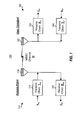
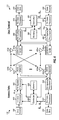
- FIG. 1 shows a block diagram of the transmit and receive portions at an access point 110 and a user terminal 150 in a TDD MIMO system 100.
- transmit symbols (denoted by a vector x dn ) are processed by a transmit chain 114 and transmitted from N ap antennas 116 and over a wireless MIMO channel having a response of H .
- the N ap downlink signals are received by N ut antennas 152 and processed by a receive chain 154 to obtain received symbols (denoted by a vector r dn ).
- the processing by transmit chain 114 typically includes digital-to-analog conversion, amplification, filtering, frequency upconversion, and so on.
- receive chain 154 typically includes frequency downconversion, amplification, filtering, analog-to-digital conversion, and so on.
- transmit symbols (denoted by a vector x up ) are processed by a transmit chain 164 and transmitted from N ut antennas 152 and over the MIMO channel.
- the N ut uplink signals are received by N ap antennas 116 and processed by a receive chain 124 to obtain received symbols (denoted by a vector r up ).
- the responses of the transmit/receive chains and the MIMO channel are typically a function of frequency. For simplicity, a flat-fading channel with a flat frequency response is assumed.
- K ut is an N ut ⁇ N
- the matrices K ap and K ut include values that account for differences in the transmit/receive chains at the access point and user terminal.
- the application of the diagonal matrices, K ap and K ut to the effective downlink and uplink channel responses, as shown in equation (5), allows the calibrated channel response for one link to be expressed by the calibrated channel response for the other link.
- Initial calibration may be performed to determine the matrices K ap and K ut .
- the true channel response H and the transmit/receive chain responses are not known nor can they be exactly or easily ascertained.
- the effective downlink and uplink channel responses, H dn and H up may be estimated based on MIMO pilots sent on the downlink and uplink, respectively.
- a MIMO pilot is a pilot comprised of N T pilot transmissions sent from N T transmit antennas, where the pilot transmission from each transmit antenna is identifiable by the receiving entity. This can be achieved, for example, by using a different orthogonal sequence for the pilot transmission from each transmit antenna.
- Estimates of the matrices K ap and K ut may then be derived based on the effective downlink and uplink channel response estimates, ⁇ dn and ⁇ up , as described below.
- the matrices K ⁇ ap and K ⁇ ut include correction factors that can account for differences in the transmit/receive chains at the access point and user terminal.
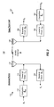
- FIG. 2 shows the use of the correction matrices K ⁇ ap and K ⁇ ut at access point 110 and user terminal 150.
- the transmit vector x dn is first multiplied with the correction matrix K ⁇ ap by a unit 112.
- the subsequent processing by transmit chain 114 and receive chain 154 for the downlink is as described in FIG. 1 .
- the transmit vector x up is first multiplied with the correction matrix K ⁇ ut by a unit 162.
- the subsequent processing by transmit chain 164 and a receive chain 124 for the uplink is also as described in FIG. 1 .
- data may be transmitted on N S eigenmodes of a MIMO channel.
- These eigenmodes may be viewed as orthogonal spatial channels of the MIMO channel.
- Table 1 shows the effective and calibrated channel responses for the downlink and uplink as well as the singular value decomposition of the calibrated downlink and uplink channel response matrices.
- U ap is an N ap ⁇
- the matrices V ⁇ ut * and U ⁇ ap * are also matrices of left and right eigenvectors, respectively, of H cdn .
- the matrices V, V *, V T and V H are different forms of the matrix V.
- reference to the matrices U ap and V ut in the following description may also refer to their other forms.
- the matrices U ap and V ut (which are also called transmit matrices) may be used by the access point and user terminal, respectively, for spatial processing and are denoted as such by their subscripts.
- the matrices H cdn and H cup are not available. Instead, the user terminal can estimate the calibrated downlink channel response based on a MIMO pilot transmitted by the access point. The user terminal can then perform singular value decomposition of the calibrated downlink channel response estimate, ⁇ cdn , to obtain a diagonal matrix ⁇ and a matrix V ⁇ ⁇ ut * of left eigenvectors of ⁇ cdn , where the hat (" ⁇ ") above each matrix indicates that it is an estimate of the actual matrix. Similarly, the access point can estimate the calibrated uplink channel response based on a MIMO pilot transmitted by the user terminal. The access point can then perform singular value decomposition of the calibrated uplink channel response estimate, ⁇ cup , to obtain the diagonal matrix ⁇ and a matrix ⁇ ap of left eigenvectors of ⁇ cup .
- the singular value decomposition only needs to be performed by either the user terminal or the access point to obtain both matrices V ⁇ ut and ⁇ ap .
- the following description is for an implementation whereby the user terminal obtains the calibrated downlink channel response estimate, ⁇ cdn , performs decomposition of ⁇ cdn , uses the matrix V ⁇ ut for spatial processing, and sends the matrix ⁇ ap back to the access point using a steered reference, as described below.
- a steered reference (or steered pilot) is a pilot that is transmitted from all antennas and on the eigenmodes of the MIMO channel.
- r up, m is a received vector for the uplink steered reference for eigenmode m
- ⁇ m is the m -
- Equation (7) shows that the received uplink steered reference at the access point, in the absence of noise, is approximately equal to û ap, m ⁇ m p m .
- the access point can obtain an estimate of the uplink channel response based on the steered reference sent by the user terminal using various estimation techniques.
- an estimate of û ap, m is obtained based on the received vector r up, m and using an MMSE technique. Since the pilot symbols p m are known, the access point can derive the estimate of û ap, m such that the mean square error between a received pilot symbol p ⁇ m (which is obtained after performing the matched filtering on the received vector r up, m with v ⁇ ut, m ) and the transmitted pilot symbol p m is minimized.
- the access point may then perform Gram-Schmidt orthogonalization on the N S eigenvector estimates to obtain orthogonal transmit vectors. In any case, the access point obtains a transmit matrix , which is an estimate of ⁇ ap , which in turn is derived by the user terminal based on ⁇ cdn .
- the access point uses the transmit matrix to perform spatial processing for downlink transmission.
- the correction matrices K ⁇ ap and K ⁇ ut obtained from the initial calibration may contain errors due to various sources such as (1) imperfect channel estimates ⁇ dn and ⁇ up used for the initial calibration, (2) changes in the transmit/receive chains at the access point and user terminal, and so on. Errors in the correction matrices cause errors in both (1) the transmit matrix V ⁇ ut used by the user terminal for spatial processing and derived from ⁇ cdn and (2) the transmit matrix ⁇ ap used by the access point for spatial processing and derived from the uplink steered reference sent using V ⁇ ut . Improved performance may be obtained if the errors in the correction matrices can be estimated and removed.
- the access point and/or the user terminal can perform follow-on calibration to estimate the errors in the correction matrices K ⁇ ap and K ⁇ ut .
- the following description is for follow-on calibration by the user terminal.
- the access point transmits a MIMO pilot on the downlink using the correction matrix K ⁇ ap and also transmits a steered reference on the downlink using the transmit matrix and the correction matrix K ⁇ ap .
- the user terminal can obtain an estimate of V ut ⁇ T based on the received downlink steered reference, similar to that described above for the uplink steered reference.
- the estimate of V ut ⁇ T derived from the downlink steered reference is called an "actual received" transmit matrix ⁇ a , which is an unnormalized matrix that includes an estimate of V ut as well as an estimate of ⁇ .
- ⁇ a is an unnormalized matrix that includes an estimate of V ut as well as an estimate of ⁇ .
- the user terminal also obtains another version of H ⁇ cdn from the MIMO pilot sent by the access point.
- the errors in the correction matrices K ⁇ ap and K ⁇ ut may be represented by diagonal calibration error matrices Q' ap and Q' ut , respectively.
- the matrices Q' ap and Q' ut contain the "true" errors in K ⁇ ap and K ⁇ ut , respectively.
- a guess or estimate of Q' ap and Q' ut may be denoted as Q ap and Q ut , respectively.
- a hypothesized downlink channel is a guess of H ⁇ dn K ap and is derived under the assumption that the error in the applied correct correction matrix K ⁇ ap is Q ap .
- the user terminal does not have the value for Q' ap , but only its guess Q ap .
- the user terminal thus computes an unnormalized transmit matrix ⁇ rx that hypothetically would have been obtained by the access point if the calibration error matrices were Q ap and Q ut , as follows:
- the user terminal then performs processing on ⁇ rx in the same manner that the access point would have performed on a received uplink steered reference and obtains a "generated" transmit matrix U g , which is a normalized transmit matrix that resembles ⁇ ap .
- the access point may perform Gram-Schmidt orthogonalization of the received eigenvectors in order to improve the performance of its transmit steering vectors.
- the user terminal would perform the same orthogonalization on the eigenvectors in ⁇ rx .
- the user terminal simply emulates the processing that is normally performed by both the access point and the user terminal, albeit under an assumption of calibration errors represented by Q ap and Q ut .
- the matrix U g would have been used by the access point to transmit the downlink steered reference and for spatial processing of downlink transmission.
- the user terminal does not have Q' ap , but only its guess Q ap .
- Equation (14) is equal to equation (13) if H hyp is a perfect guess of ⁇ dn K ap and Q ap is a perfect guess of Q' ap .
- the matrix ⁇ hyp is an unnormalized matrix that includes a user terminal transmit matrix V g (which corresponds to the access point transmit matrix U g ) as well as a diagonal matrix ⁇ g (which resembles ⁇ ).
- the matrix ⁇ hyp is hypothesized to have been received by the user terminal with (1) the user terminal transmitting an uplink steered reference using V ⁇ ut , (2) the access point performing its normal processing on the received uplink steered reference to derive its transmit matrix U g , (3) the access point transmitting a downlink steered reference using U g , (4) the correction matrices K ⁇ ap and K ⁇ ut having the errors indicated by the matrices Q ap and Q ut , respectively, and (5) assuming no channel estimation error in ⁇ cdn from the downlink MIMO pilot.
- Equations (12) and (14) are correct if the calibration error matrices Q ap and Q ut correctly indicate the true errors in the correction matrices K ⁇ ap and K ⁇ ut , respectively.
- the error matrix E gives an indication of the accuracy of the guess for Q ap and Q ut .
- Various adaptive procedures may be used to adjust the matrices Q ap and Q ut to drive the error matrix E toward zero.
- Such adaptive procedures include an MMSE adaptive procedure and a steepest descent adaptive procedure.
- the diagonal elements of Q ap and Q ut may be initialized to 1 + j 0 for the adaptive procedures.
- a set of phases may be selected to make ⁇ hyp close to ⁇ a without any loss in generality.
- This property allows for scaling of Q ut by an arbitrary unit-magnitude factor, so the imaginary component of the lead element of Q ut may be defined to be 0.0.
- the MMSE adaptive procedure may be performed as follows. Let q be a real vector of length 2(N ap + N ut - 2) and made up of the real and imaginary components of the diagonal elements of Q ap and Q ut , except for the lead elements which are set to 1.0.
- the odd-indexed elements of q are for the real component of the diagonal elements of Q ap and Q ut
- the even-indexed elements of q are for the imaginary component of the diagonal elements of Q ap and Q ut .
- the first 2N ap - 2 elements of q are for the N ap -1 diagonal elements other than the lead element of Q ap
- the last 2N ut - 2 elements of q are for the N ut - 1 diagonal elements other than the lead element of Q ut .
- e be a real vector of length 2N ap N ut and made up of the real and imaginary components of the elements of E .
- the odd-indexed elements of e are for the real component of the elements of E
- the even-indexed elements of e are for the imaginary component of the elements of E .
- the error vector e can be obtained by evaluating equations (10), (12), (14), and (15) with the vector q .
- the partial derivative of a real or imaginary component of an element in E with respect to a real or imaginary component of an element in Q ap or Q ut may be generated by perturbing the component of the element in Q ap or Q ut and computing the function defined by equations (10), (12), (14), and (15).
- ⁇ hyp a single e jx term may be selected such that
- ⁇ j is a vector of length 2(N ap + N ut - 2) and containing a small real value of ⁇ for the j -th element and zeros elsewhere; and
- a j,i is the approximate partial derivative of the j -th element of e with respect to the i -th element of q .
- a vector q i q + ⁇ i .
- Equation (10), (12), (14), and (15) is performed for each of the 2(N ap + N ut - 2) elements of q to obtain a corresponding new error vector e i .
- the 2N ap N ut elements of e are subtracted from the 2N ap N ut elements of e i , on an element-by-element basis, to obtain 2N ap N ut approximate partial derivatives of the 2N ap N ut elements of e with respect to the i -th element of q .
- a matrix A of dimension 2N ap N ut by 2(N ap + N ut - 2) may be formed with all of the partial derivatives for all of the elements of e and q .
- Each column of A contains 2N ap N ut approximate partial derivatives for the 2N ap N ut elements of e with respect to one element of q .
- the 2(N ap + N ut - 2) columns of A are for the 2(N ap + N ut - 2) elements q .
- the update vector y has the same format and dimension as the vector q , which is a real vector made up of the real and imaginary components of the diagonal elements of Q ap and Q ut other than the lead elements.
- A is not a square matrix, which is typically the case, then the simple matrix inverse does not exist.
- the Moore-Penrose pseudo-inverse of A may then be used for equation (17).
- the matrix A of partial derivatives is computed under an assumption that the function defined by equations (10) through (13) is approximately linear for calibration errors of the size being evaluated. Since the linearity assumption is not completely accurate, the procedure may be iterated multiple times to determine the correct calibration errors. For some cases, the procedure does not converge. However, convergence can generally be achieved by simply selecting a different initial guess for the calibration errors. If convergence is not obtained, the user terminal can also obtain another version of ⁇ a and ⁇ cdn based on another estimate of the downlink steered reference and downlink MIMO pilot and perform the MMSE adaptive procedure using these new matrices.
- Equation (10), (12), (14), and (15) are linear, then y + q would minimize the mean square of the elements of e. However, since these equations are not linear, q is replaced with y + q and the procedure is repeated.
- each iteration uses the updated calibration error vector q mmse ( n + 1) obtained from the prior iteration.
- the procedure can terminate when the update vector y ( n ) is sufficiently small.
- the termination condition may be y i ⁇ y th 2 , for all i , where y i is the i -th element of y ( n ) and y th 2 is another threshold value.
- the aggregate error, z is obtained by summing the squares of the magnitude of the elements of E .
- the approximate partial derivative g i may be obtained as follows. A vector q i .
- a vector g of dimension 2(N ap + N ut - 2) may be formed with the approximate partial derivates obtained for the 2(N ap + N ut - 2) elements of q .
- Each element of g is the slope of the aggregate error evaluated at a corresponding element of q .
- the computation described above may be repeated for any number of iterations.
- Each iteration uses the updated calibration error vector q sd ( n + 1) obtained from the prior iteration.
- the procedure can terminate when the aggregate error z is sufficiently small, e.g., less then a z th threshold value.
- the user terminal uses the new correction matrix K ⁇ ut ,new , instead of the prior correction matrix K ⁇ ut , for spatial processing for uplink transmission, as shown in FIG. 2 .
- the user terminal may only send back the calibration error matrix Q ap, final if the matrix meets some predetermined threshold.
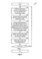
- FIG. 3 shows a process 300 performed by the access point and user terminal for initial calibration, normal operation, and follow-on calibration.
- the access point and user terminal perform initial calibration to calibrate their transmit and receive chains and derive correction matrices K ⁇ ap and K ⁇ ut (block 310).
- the initial calibration is described below.
- the access point transmits a downlink MIMO pilot using its correction matrix K ⁇ ap (block 322).
- the user terminal obtains a calibrated downlink channel response estimate, ⁇ cdn , based on the downlink MIMO pilot (block 324) and performs singular value decomposition of ⁇ cdn , to obtain its transmit matrix V ⁇ ut (block 326).
- the user terminal transmits an uplink steered reference using V ⁇ ut and K ⁇ ut , as shown in equation (6) (block 328).
- the access point receives the uplink steered reference and derives its transmit matrix , as described above (block 330).
- the access point and user terminal use the transmit matrices and V ⁇ ut , respectively, for spatial processing.
- the access point transmits a downlink steered reference using and K ⁇ ap , and further transmits a downlink MIMO pilot using K ⁇ ap (block 342).
- the user terminal derives the actual unnormalized transmit matrix ⁇ a based on the downlink steered reference, as described above (block 344).
- the user terminal further processes ⁇ rx in the same manner as would have been performed by the access point (e.g., perform orthogonalization) to obtain the normalized transmit matrix U g (block 348).
- the matrix ⁇ hyp is the unnormalized transmit matrix that the user terminal would have received if the access point transmits a downlink steered reference using U g .
- the user terminal then revises the calibration error matrices Q ap and Q ut based on the transmit matrices V ⁇ a and ⁇ hyp (block 352). Blocks 346 through 352 may be performed using an adaptive procedure.
- the user terminal may thereafter update its correction matrix K ⁇ ut with the calibration error matrix Q ut (block 354), and the access point may thereafter update its correction matrix K ⁇ ap with the calibration error matrix Q ap (block 356).
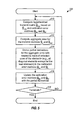
- FIG. 4 shows an MMSE adaptive procedure 400, which may be used for blocks 346 through 352 in FIG. 3 .
- the hypothesized transmit matrix ⁇ hyp is first computed based on ⁇ cdn and Q ap and Q ut (block 410).
- Block 410 corresponds to blocks 346 through 350 in FIG. 3 .
- the error matrix E is next computed as the difference between the transmit matrices ⁇ a and ⁇ hyp , as shown in equation (15) (block 412).
- Partial derivatives for each of the elements in the error matrix E with respect to each of selected ones of the elements (e.g., all diagonal elements except for the lead elements) in the calibration error matrices Q ap and Q ut are then derived, as shown in equation (16) (block 414).
- the matrix E and the matrices Q ap and Q ut may be placed in the form of vectors for ease of computation, as described above.
- the partial derivatives may be derived separately for the real and imaginary components of the elements in the matrices, as also described above.
- the update vector y is then computed based on the matrix A of partial derivatives and the error matrix E, as shown in equation (17) (block 416).
- the calibration error matrices Q ap and Q ut are then updated with the update vector y , as shown in equation (18) (block 418).
- a determination is next made whether or not the update vector y satisfies a termination condition (block 420). If the answer is 'yes', then process 400 terminates. Otherwise, the process returns to block 410 and performs another iteration.
- FIG. 5 shows a steepest descent adaptive procedure 500, which may also be used for blocks 346 through 352 in FIG. 3 .
- the hypothesized transmit matrix ⁇ hyp is first computed based on H ⁇ cdn and Q ap and Q ut (block 510).
- Partial derivatives for the aggregate error with respect to each of selected ones of the elements in the calibration error matrices Q ap and Q ut are then derived, as shown in equation (20) (block 514).
- the matrices Q ap and Q ut may be placed in the form of a vector, and the partial derivatives may be derived separately for the real and imaginary components of the elements in the matrices.
- the calibration error matrices Q ap and Q ut are then updated with the partial derivatives, as shown in equation (21) (block 516).
- a determination is next made whether or not the aggregate error z satisfies a termination condition (block 518). If the answer is 'yes', then process 500 terminates. Otherwise, the process returns to block 510 and performs another iteration.
- the user terminal estimates the calibration errors in both the correction matrices K ⁇ ap and K ⁇ ut .
- the user terminal can assume that the correction matrix K ⁇ ap contains no errors and only estimate the errors in the correction matrix K ⁇ ut . This is equivalent to setting the calibration error matrix Q ap to the identity matrix. By omitting Q ap , the dimensions of the vectors q , y , and g and the matrix A are reduced, which may then greatly reduce the computation.
- the access point may also perform the follow-on calibration.
- the access point and user terminal switches role in FIG. 3 .
- the user terminal would then transmit an uplink steered reference and an uplink MIMO pilot, and the access point would perform the computation to derive Q ap and Q ut .
- the follow-on calibration is described for a single-carrier MIMO system.
- the follow-on calibration may also be performed for a multi-carrier MIMO system, which may utilize orthogonal frequency division multiplexing (OFDM) or some other multi-carrier modulation technique.
- OFDM effectively partitions the overall system bandwidth into multiple (N F ) orthogonal subbands, which are also called tones, subcarriers, bins, and frequency channels.
- N F orthogonal frequency division multiplexing
- each subband is associated with a respective subcarrier that may be modulated with data.
- the computation described above may be performed for each of multiple subbands. Since a high degree of correlation may exist between nearby subbands, the calibration may be performed in a manner to take advantage of this correlation, for example, to reduce the number of subbands to perform follow-on calibration, to speed up convergence, and so on.
- one entity obtains both the effective downlink channel response estimate, ⁇ dn , and the effective uplink channel response estimate, ⁇ up .
- the channel estimates ⁇ dn and ⁇ up may be obtained based on downlink and uplink MIMO pilots, respectively.
- the correction matrices may be computed from ⁇ dn and ⁇ up and using matrix-ratio computation or MMSE computation.
- the diagonal elements in the correction matrix K ⁇ ap for the access point are set equal to the mean of the normalized rows of C.
- Each row of C is first normalized by scaling each of the N ap elements in that row with the first element in the row.
- the mean of the normalized rows (denoted by a vector c ⁇ row ) is then computed as the sum of the N ut normalized rows divided by N ut .
- the N ap diagonal elements of K ⁇ ap are then set equal to the N ap elements of c ⁇ row . Because of the normalization, the lead element of K ⁇ ap is equal to unity.
- the diagonal elements in the correction matrix K ⁇ ut for the user terminal are set equal to the mean of the inverses of the normalized columns of C .
- the mean of the inverses of the normalized columns (denoted by a vector c ⁇ col ) is then computed by (1) taking the inverse of each normalized column, where the inversion is performed element-wise, (2) summing the N ap inverse normalized columns, and (3) dividing each element in the resultant column by N ap to obtain c ⁇ col .
- the N ut diagonal elements of K ⁇ ut are set equal to the N ut elements of c ⁇ col .
- the correction matrices K ⁇ ap and K ⁇ ut are derived from the effective downlink and uplink channel response estimates, ⁇ dn and ⁇ up , such that the mean square error (MSE) between the calibrated downlink and uplink channel responses is minimized.
- MSE mean square error
- Equation (24) is subject to the constraint that the lead element of K ⁇ ap is set equal to unity. Without this constraint, the trivial solution would be obtained with all elements of the matrices K ⁇ ap and K ⁇ ut set equal to zero.
- the square of the absolute value is next obtained for each of the N ap N ut elements of Y .
- the mean square error (or the square error since a divide by N ap N ut is omitted) is then equal to the sum of all squared values.
- the MMSE computation is performed as follows.
- the elements of ⁇ dn are denoted as ⁇ a ij ⁇
- the elements of ⁇ up are denoted as ⁇ b ij ⁇
- the diagonal elements of K ⁇ ap are denoted as ⁇ u i ⁇
- the minimum mean square error may be obtained by taking the partial derivatives of equation (25) with respect to u and v and setting the partial derivatives to zero.
- the matrix B includes N ap + N ut - 1 rows, with the first N ap -1 rows corresponding to the N ap -1 equations from equation set (26a) and the last N ut rows corresponding to the N ut equations from equation set (26b).
- the elements of the matrix B and the vector z may be obtained based on the elements of ⁇ dn and ⁇ up .
- the results of the MMSE computation are correction matrices K ⁇ ap and K ⁇ ut that minimize the mean square error in the calibrated downlink and uplink channel responses, as shown in equation (24).
- Table 2 summarizes the spatial processing performed by the user terminal and access point for data transmission and reception on the eigenmodes of the MIMO channel.
- the correction matrices K ⁇ ap and K ⁇ ut are applied on the transmit side at the access point and user terminal, respectively.
- FIG. 6 shows a block diagram of an embodiment of access point 110 and user terminal 150 in TDD MIMO system 100.
- a transmit (TX) data processor 610 receives traffic data (i.e., information bits) from a data source 608 and signaling and other data from a controller 630.
- TX data processor 610 formats, codes, interleaves, and modulates (or symbol maps) the different types of data and provides data symbols.
- a "data symbol” is a modulation symbol for data
- a "pilot symbol” is a modulation symbol for pilot.
- the pilot symbols are known a priori by both the access point and user terminal.
- a TX spatial processor 620 receives the data symbols from TX data processor 610, performs spatial processing on the data symbols, multiplexes in pilot symbols as appropriate (e.g., for channel estimation, calibration, and so on), and provides N ap streams of transmit symbols to N ap modulators (MOD) 622a through 622ap.
- Each modulator 622 receives and processes a respective transmit symbol stream to obtain a corresponding stream of OFDM symbols, which is further processed by a transmit chain within the modulator to obtain a corresponding downlink modulated signal.
- N ap downlink modulated signals from modulator 622a through 622ap are then transmitted from N ap antennas 624a through 624ap, respectively.
- N ut antennas 652a through 652ut receive the transmitted downlink modulated signals, and each antenna provides a received signal to a respective demodulator (DEMOD) 654.
- Each demodulator 654 (which includes a receive chain) performs processing complementary to that performed at modulator 622 and provides received symbols.
- a receive (RX) spatial processor 660 then performs receiver spatial processing on the received symbols from all N ut demodulators 654 to obtain detected symbols, which are estimates of the data symbols sent by the access point.
- RX spatial processor 660 provides (1) a calibrated downlink channel response estimate, ⁇ cdn , obtained from a downlink MIMO pilot transmitted by the access point and (2) received symbols for a downlink steered reference transmitted by the access point.
- An RX data processor 670 processes (e.g., symbol demaps, deinterleaves, and decodes) the detected symbols and provides decoded data.
- the decoded data may include recovered traffic data, signaling, and so on, which are provided to a data sink 672 for storage and/or a controller 680 for further processing.
- the processing for the uplink may be the same or different from the processing for the downlink.
- Data and signaling are processed (e.g., coded, interleaved, and modulated) by a TX data processor 690, and further spatially processed and multiplexed with pilot symbols by TX spatial processor 692 to obtain transmit symbols.
- the transmit symbols are further processed by modulators 654a through 654ut to obtain N ut uplink modulated signals, which are then transmitted via N ut antennas 652a through 652ut to the access point.
- User terminal 150 sends back the correction K ⁇ ap for the initial calibration and may send back the calibration error matrix Q ap, final for the follow-on calibration, for the implementation described above.
- the uplink modulated signals are received by antennas 624, demodulated by demodulators 622, and processed by an RX spatial processor 640 and an RX data processor 642 in a complementary to that performed at the user terminal.
- RX data processor 642 provides the matrices K ⁇ ap and Q ap, final to controller 630.
- the access point and user terminal transmit MIMO pilots on the downlink and uplink, respectively.
- Each entity derives the effective channel response estimate for its link.
- One entity e.g., the access point
- sends the channel estimate to the other entity e.g., the user terminal
- the entity that derives the correction matrices uses its correction matrix and sends the other correction matrix back to the other entity.
- one entity e.g., the access point
- the other derives the calibration error matrices Q ap, final and Q ut, final for both entities based on the received pilots, as described above.
- the entity that derives the calibration error matrices uses its calibration error matrix and may send the other calibration error matrix back to the other entity (e.g., if the errors are sufficiently large).
- Controllers 630 and 680 control the operation of various processing units at the access point and user terminal, respectively. Controllers 630 and/or 680 may also perform processing for the initial and follow-on calibration (e.g., the computation for the correction matrices K ⁇ ap and K ⁇ ut and the calibration error matrices Q ap, final and Q ut, final ). Memory units 632 and 682 store data and program codes used by controllers 630 and 680, respectively.
- the calibration techniques described herein may be implemented by various means. For example, these techniques may be implemented in hardware, software, or a combination thereof.
- the processing units used to perform the initial and/or follow-on calibration may be implemented within one or more application specific integrated circuits (ASICs), digital signal processors (DSPs), digital signal processing devices (DSPDs), programmable logic devices (PLDs), field programmable gate arrays (FPGAs), processors, controllers, micro-controllers, microprocessors, other electronic units designed to perform the functions described herein, or a combination thereof.
- ASICs application specific integrated circuits
- DSPs digital signal processors
- DSPDs digital signal processing devices
- PLDs programmable logic devices
- FPGAs field programmable gate arrays
- processors controllers, micro-controllers, microprocessors, other electronic units designed to perform the functions described herein, or a combination thereof.
- the calibration techniques may be implemented with modules (e.g., procedures, functions, and so on) that perform the functions described herein.
- the software codes may be stored in a memory unit (e.g., memory unit 632 or 682 in FIG. 6 ) and executed by a processor (e.g., controller 630 or 680).
- the memory unit may be implemented within the processor or external to the processor, in which case it can be communicatively coupled to the processor via various means as is known in the art.
Applications Claiming Priority (2)
| Application Number | Priority Date | Filing Date | Title |
|---|---|---|---|
| US10/783,175 US7206354B2 (en) | 2004-02-19 | 2004-02-19 | Calibration of downlink and uplink channel responses in a wireless MIMO communication system |
| PCT/US2005/005262 WO2005081483A1 (en) | 2004-02-19 | 2005-02-18 | Calibration of downlink and uplink channel responses in a wireless mimo communication system |
Publications (2)
| Publication Number | Publication Date |
|---|---|
| EP1721431A1 EP1721431A1 (en) | 2006-11-15 |
| EP1721431B1 true EP1721431B1 (en) | 2015-11-04 |
Family
ID=34861168
Family Applications (1)
| Application Number | Title | Priority Date | Filing Date |
|---|---|---|---|
| EP05723308.2A Active EP1721431B1 (en) | 2004-02-19 | 2005-02-18 | Calibration of downlink and uplink channel responses in a wireless MIMO communication system |
Country Status (9)
| Country | Link |
|---|---|
| US (1) | US7206354B2 (es) |
| EP (1) | EP1721431B1 (es) |
| JP (2) | JP5269320B2 (es) |
| KR (1) | KR100809896B1 (es) |
| CN (1) | CN1943194B (es) |
| CA (1) | CA2556710C (es) |
| ES (1) | ES2561466T3 (es) |
| TW (1) | TWI361601B (es) |
| WO (1) | WO2005081483A1 (es) |
Families Citing this family (85)
| Publication number | Priority date | Publication date | Assignee | Title |
|---|---|---|---|---|
| US8194770B2 (en) | 2002-08-27 | 2012-06-05 | Qualcomm Incorporated | Coded MIMO systems with selective channel inversion applied per eigenmode |
| US7002900B2 (en) | 2002-10-25 | 2006-02-21 | Qualcomm Incorporated | Transmit diversity processing for a multi-antenna communication system |
| US8170513B2 (en) | 2002-10-25 | 2012-05-01 | Qualcomm Incorporated | Data detection and demodulation for wireless communication systems |
| US8320301B2 (en) | 2002-10-25 | 2012-11-27 | Qualcomm Incorporated | MIMO WLAN system |
| US7324429B2 (en) | 2002-10-25 | 2008-01-29 | Qualcomm, Incorporated | Multi-mode terminal in a wireless MIMO system |
| US8169944B2 (en) | 2002-10-25 | 2012-05-01 | Qualcomm Incorporated | Random access for wireless multiple-access communication systems |
| US8134976B2 (en) | 2002-10-25 | 2012-03-13 | Qualcomm Incorporated | Channel calibration for a time division duplexed communication system |
| US8208364B2 (en) | 2002-10-25 | 2012-06-26 | Qualcomm Incorporated | MIMO system with multiple spatial multiplexing modes |
| US7986742B2 (en) * | 2002-10-25 | 2011-07-26 | Qualcomm Incorporated | Pilots for MIMO communication system |
| US8218609B2 (en) * | 2002-10-25 | 2012-07-10 | Qualcomm Incorporated | Closed-loop rate control for a multi-channel communication system |
| US8570988B2 (en) | 2002-10-25 | 2013-10-29 | Qualcomm Incorporated | Channel calibration for a time division duplexed communication system |
| US20040081131A1 (en) | 2002-10-25 | 2004-04-29 | Walton Jay Rod | OFDM communication system with multiple OFDM symbol sizes |
| US9473269B2 (en) | 2003-12-01 | 2016-10-18 | Qualcomm Incorporated | Method and apparatus for providing an efficient control channel structure in a wireless communication system |
| US8204149B2 (en) | 2003-12-17 | 2012-06-19 | Qualcomm Incorporated | Spatial spreading in a multi-antenna communication system |
| US7336746B2 (en) | 2004-12-09 | 2008-02-26 | Qualcomm Incorporated | Data transmission with spatial spreading in a MIMO communication system |
| US8169889B2 (en) | 2004-02-18 | 2012-05-01 | Qualcomm Incorporated | Transmit diversity and spatial spreading for an OFDM-based multi-antenna communication system |
| US7206354B2 (en) * | 2004-02-19 | 2007-04-17 | Qualcomm Incorporated | Calibration of downlink and uplink channel responses in a wireless MIMO communication system |
| US7356017B2 (en) * | 2004-02-19 | 2008-04-08 | Nokia Corporation | Data loading method, transmitter, and base station |
| US8285226B2 (en) * | 2004-05-07 | 2012-10-09 | Qualcomm Incorporated | Steering diversity for an OFDM-based multi-antenna communication system |
| US8923785B2 (en) * | 2004-05-07 | 2014-12-30 | Qualcomm Incorporated | Continuous beamforming for a MIMO-OFDM system |
| US7978649B2 (en) * | 2004-07-15 | 2011-07-12 | Qualcomm, Incorporated | Unified MIMO transmission and reception |
| JP4744965B2 (ja) * | 2004-08-09 | 2011-08-10 | パナソニック株式会社 | 無線通信装置 |
| US7680212B2 (en) * | 2004-08-17 | 2010-03-16 | The Board Of Trustees Of The Leland Stanford Junior University | Linear precoding for multi-input systems based on channel estimate and channel statistics |
| US7872981B2 (en) * | 2005-05-12 | 2011-01-18 | Qualcomm Incorporated | Rate selection for eigensteering in a MIMO communication system |
| US7466749B2 (en) | 2005-05-12 | 2008-12-16 | Qualcomm Incorporated | Rate selection with margin sharing |
| US8498669B2 (en) | 2005-06-16 | 2013-07-30 | Qualcomm Incorporated | Antenna array calibration for wireless communication systems |
| US8358714B2 (en) | 2005-06-16 | 2013-01-22 | Qualcomm Incorporated | Coding and modulation for multiple data streams in a communication system |
| KR20070032548A (ko) * | 2005-09-16 | 2007-03-22 | 삼성전자주식회사 | 다중 안테나를 사용하는 무선통신시스템에서 채널 보정장치 및 방법 |
| US9118111B2 (en) | 2005-11-02 | 2015-08-25 | Qualcomm Incorporated | Antenna array calibration for wireless communication systems |
| US8280430B2 (en) | 2005-11-02 | 2012-10-02 | Qualcomm Incorporated | Antenna array calibration for multi-input multi-output wireless communication systems |
| RU2395163C2 (ru) * | 2005-11-02 | 2010-07-20 | Квэлкомм Инкорпорейтед | Калибровка антенной матрицы для многовходовых многовыходных систем беспроводной связи |
| WO2007103085A2 (en) | 2006-03-01 | 2007-09-13 | Interdigital Technology Corporation | Method and apparatus for calibration and channel state feedback to support transmit beamforming in a mimo system |
| US8543070B2 (en) * | 2006-04-24 | 2013-09-24 | Qualcomm Incorporated | Reduced complexity beam-steered MIMO OFDM system |
| US8290089B2 (en) * | 2006-05-22 | 2012-10-16 | Qualcomm Incorporated | Derivation and feedback of transmit steering matrix |
| JP4836186B2 (ja) * | 2006-05-31 | 2011-12-14 | 三洋電機株式会社 | 送信装置 |
| JP5133346B2 (ja) | 2006-09-18 | 2013-01-30 | マーベル ワールド トレード リミテッド | 無線mimo通信システムにおける暗黙のビームフォーミングのキャリブレーション補正法 |
| US7746766B2 (en) * | 2006-09-21 | 2010-06-29 | Sharp Laboratories Of America, Inc. | Systems and methods for obtaining an optimum transmission format of reference signals to maximize capacity and minimize peak to average power ratio |
| US8055226B2 (en) * | 2006-10-18 | 2011-11-08 | Tektronix, Inc. | Frequency response correction for a receiver having a frequency translation device |
| JP5127269B2 (ja) | 2007-03-07 | 2013-01-23 | キヤノン株式会社 | 無線通信装置、無線通信方法、当該無線通信方法をコンピュータに実行させるためのコンピュータプログラム |
| US8379745B1 (en) | 2007-07-06 | 2013-02-19 | Marvell International Ltd. | Forward channel variation detection in a wireless communication system |
| US8095097B1 (en) | 2007-08-06 | 2012-01-10 | Marvell International Ltd. | Increasing the robustness of channel estimates derived through sounding for WLAN |
| US8559571B2 (en) * | 2007-08-17 | 2013-10-15 | Ralink Technology Corporation | Method and apparatus for beamforming of multi-input-multi-output (MIMO) orthogonal frequency division multiplexing (OFDM) transceivers |
| US7986755B2 (en) * | 2007-08-17 | 2011-07-26 | Ralink Technology Corporation | Method and apparatus for calibration for beamforming of multi-input-multi-output (MIMO) orthogonol frequency division multiplexing (OFDM) transceivers |
| US8229017B1 (en) | 2007-12-13 | 2012-07-24 | Marvell International Ltd. | Transmit beamforming utilizing channel estimation matrix decomposition feedback in a wireless MIMO communication system |
| CN101604991B (zh) * | 2008-06-13 | 2013-01-02 | 展讯通信(上海)有限公司 | 一种mimo系统中射频通道参数估计方法与装置 |
| US20090323783A1 (en) * | 2008-06-25 | 2009-12-31 | Motorola, Inc. | Calibration techniques for mimo wireless communication systems |
| CN101626353B (zh) * | 2008-07-07 | 2012-01-25 | 上海华为技术有限公司 | 一种数据通信方法、设备及系统 |
| JP5149111B2 (ja) * | 2008-09-09 | 2013-02-20 | 株式会社エヌ・ティ・ティ・ドコモ | 無線中継装置及び無線中継方法 |
| CN101374124B (zh) * | 2008-09-27 | 2011-11-30 | 上海微电子装备有限公司 | 信道增益数字均衡自适应校准系统与方法 |
| EP2398111B1 (en) * | 2009-02-12 | 2017-09-27 | Mitsubishi Electric Corporation | Calibration device |
| WO2010148554A1 (zh) * | 2009-06-23 | 2010-12-29 | 上海贝尔股份有限公司 | 时分双工复用mimo系统中的信号发送方法及装置 |
| CN101626355B (zh) * | 2009-08-11 | 2012-11-14 | 北京天碁科技有限公司 | 一种多输入多输出终端的校准装置及校准方法 |
| US8660497B1 (en) | 2009-08-18 | 2014-02-25 | Marvell International Ltd. | Beamsteering in a spatial division multiple access (SDMA) system |
| CN101662446B (zh) * | 2009-09-28 | 2013-01-16 | 中兴通讯股份有限公司 | 信道估计方法及装置 |
| EP2536036A4 (en) * | 2010-02-12 | 2015-07-08 | Alcatel Lucent | DEVICE AND METHOD FOR CALIBRATING RECIPROCITY ERRORS |
| US8971178B1 (en) | 2010-04-05 | 2015-03-03 | Marvell International Ltd. | Calibration correction for implicit beamformer using an explicit beamforming technique in a wireless MIMO communication system |
| US9444577B1 (en) | 2010-04-05 | 2016-09-13 | Marvell International Ltd. | Calibration correction for implicit beamformer using an explicit beamforming technique in a wireless MIMO communication system |
| CN102082745B (zh) * | 2010-04-19 | 2013-10-16 | 电信科学技术研究院 | 天线校准信息的上报、天线校准因子的确定方法及设备 |
| KR101923200B1 (ko) | 2010-06-16 | 2018-11-29 | 마벨 월드 트레이드 리미티드 | 통신 네트워크에서 하향링크 다중 사용자 mimo 구성을 위한 대안적인 피드백 방법 및 시스템 |
| WO2012021449A1 (en) * | 2010-08-10 | 2012-02-16 | Marvell World Trade Ltd. | Sub-band feedback for beamforming on downlink multiple user mimo configurations |
| US9154969B1 (en) | 2011-09-29 | 2015-10-06 | Marvell International Ltd. | Wireless device calibration for implicit transmit |
| US9294179B2 (en) * | 2012-02-07 | 2016-03-22 | Google Technology Holdings LLC | Gain normalization correction of PMI and COI feedback for base station with antenna array |
| US9503170B2 (en) | 2012-06-04 | 2016-11-22 | Trustees Of Tufts College | System, method and apparatus for multi-input multi-output communications over per-transmitter power-constrained channels |
| US20140160957A1 (en) * | 2012-12-11 | 2014-06-12 | Broadcom Corporation | Channel state information calibration |
| US9661579B1 (en) | 2013-05-03 | 2017-05-23 | Marvell International Ltd. | Per-tone power control in OFDM |
| CN110035442B (zh) * | 2013-05-24 | 2022-03-15 | 日本电信电话株式会社 | 无线通信装置以及无线通信方法 |
| US9843097B1 (en) | 2013-07-08 | 2017-12-12 | Marvell International Ltd. | MIMO implicit beamforming techniques |
| US10038996B1 (en) | 2013-07-09 | 2018-07-31 | Marvell International Ltd. | User group selection in multiple user multiple input multiple output (MU-MIMO) configurations |
| WO2015168639A1 (en) | 2014-05-02 | 2015-11-05 | Marvell World Trade Ltd. | Multiple user allocation signaling in a wireless communication network |
| US9590745B2 (en) | 2014-11-20 | 2017-03-07 | Mediatek Inc. | Scheme for performing beamforming calibration by measuring joint signal path mismatch |
| WO2016104930A1 (ko) * | 2014-12-22 | 2016-06-30 | 주식회사 엘지화학 | 관능기가 도입된 아미노실란계 말단변성제, 이를 이용하는 말단변성 공역디엔계 중합체의 제조방법, 및 이에 따라 제조한 말단변성 공역디엔계 중합체 |
| CN104601257B (zh) * | 2015-01-14 | 2017-03-29 | 东南大学 | 一种时分双工通信模式下多天线系统的互易性校准方法 |
| US10306603B1 (en) | 2015-02-09 | 2019-05-28 | Marvell International Ltd. | Resource request for uplink multi-user transmission |
| US9826532B1 (en) | 2015-02-09 | 2017-11-21 | Marvell International Ltd. | Orthogonal frequency division multiple access resource request |
| US9722730B1 (en) | 2015-02-12 | 2017-08-01 | Marvell International Ltd. | Multi-stream demodulation schemes with progressive optimization |
| EP3304765B1 (en) | 2015-06-08 | 2021-04-28 | Marvell Asia Pte, Ltd. | Explicit beamforming in a high efficiency wireless local area network |
| US9590708B1 (en) * | 2015-08-25 | 2017-03-07 | Motorola Mobility Llc | Method and apparatus for equal energy codebooks for antenna arrays with mutual coupling |
| EP3443793A2 (en) | 2016-04-12 | 2019-02-20 | Marvell World Trade Ltd. | Uplink multi-user transmission |
| US10574418B2 (en) | 2016-04-14 | 2020-02-25 | Marvell World Trade Ltd. | Determining channel availability for orthogonal frequency division multiple access operation |
| KR102045287B1 (ko) | 2016-12-15 | 2019-11-15 | 고려대학교 산학협력단 | 무선 통신 시스템, 액세스 포인트 장치, 무선 통신 방법, 상기 방법을 수행하기 위한 프로그램 및 컴퓨터로 읽을 수 있는 기록 매체 |
| CN111130661B (zh) * | 2018-10-31 | 2021-08-31 | 华为技术有限公司 | 一种天线校正方法及装置 |
| US10505599B1 (en) | 2018-12-19 | 2019-12-10 | Marvell International Ltd. | Matrix equalization computation with pipelined architecture |
| CN110266620B (zh) * | 2019-07-08 | 2020-06-30 | 电子科技大学 | 基于卷积神经网络的3d mimo-ofdm系统信道估计方法 |
| US11777567B2 (en) * | 2021-04-30 | 2023-10-03 | Aptiv Technologies Limited | Independent transmit and receive channel calibration for multiple-input multiple-output (MIMO) systems |
| CN114142986B (zh) * | 2021-12-06 | 2023-12-26 | 东南大学 | 基于接入点分组的上下行信道互易性空口校准方法 |
Family Cites Families (10)
| Publication number | Priority date | Publication date | Assignee | Title |
|---|---|---|---|---|
| EP0931388B1 (en) * | 1996-08-29 | 2003-11-05 | Cisco Technology, Inc. | Spatio-temporal processing for communication |
| US6771706B2 (en) * | 2001-03-23 | 2004-08-03 | Qualcomm Incorporated | Method and apparatus for utilizing channel state information in a wireless communication system |
| US7027523B2 (en) * | 2001-06-22 | 2006-04-11 | Qualcomm Incorporated | Method and apparatus for transmitting data in a time division duplexed (TDD) communication system |
| US6801580B2 (en) * | 2002-04-09 | 2004-10-05 | Qualcomm, Incorporated | Ordered successive interference cancellation receiver processing for multipath channels |
| US6862440B2 (en) * | 2002-05-29 | 2005-03-01 | Intel Corporation | Method and system for multiple channel wireless transmitter and receiver phase and amplitude calibration |
| US8320301B2 (en) * | 2002-10-25 | 2012-11-27 | Qualcomm Incorporated | MIMO WLAN system |
| US8134976B2 (en) | 2002-10-25 | 2012-03-13 | Qualcomm Incorporated | Channel calibration for a time division duplexed communication system |
| US7151809B2 (en) | 2002-10-25 | 2006-12-19 | Qualcomm, Incorporated | Channel estimation and spatial processing for TDD MIMO systems |
| US7236535B2 (en) * | 2002-11-19 | 2007-06-26 | Qualcomm Incorporated | Reduced complexity channel estimation for wireless communication systems |
| US7206354B2 (en) * | 2004-02-19 | 2007-04-17 | Qualcomm Incorporated | Calibration of downlink and uplink channel responses in a wireless MIMO communication system |
-
2004
- 2004-02-19 US US10/783,175 patent/US7206354B2/en active Active
-
2005
- 2005-02-18 EP EP05723308.2A patent/EP1721431B1/en active Active
- 2005-02-18 CA CA2556710A patent/CA2556710C/en active Active
- 2005-02-18 CN CN200580011876.5A patent/CN1943194B/zh active Active
- 2005-02-18 TW TW094104760A patent/TWI361601B/zh active
- 2005-02-18 ES ES05723308.2T patent/ES2561466T3/es active Active
- 2005-02-18 KR KR1020067019327A patent/KR100809896B1/ko active IP Right Grant
- 2005-02-18 WO PCT/US2005/005262 patent/WO2005081483A1/en active Application Filing
- 2005-02-18 JP JP2006554245A patent/JP5269320B2/ja active Active
-
2011
- 2011-03-02 JP JP2011045443A patent/JP5496931B2/ja active Active
Also Published As
| Publication number | Publication date |
|---|---|
| CA2556710C (en) | 2011-12-20 |
| JP2007523570A (ja) | 2007-08-16 |
| JP2011160440A (ja) | 2011-08-18 |
| KR20060125908A (ko) | 2006-12-06 |
| TWI361601B (en) | 2012-04-01 |
| JP5269320B2 (ja) | 2013-08-21 |
| US20050185728A1 (en) | 2005-08-25 |
| TW200605582A (en) | 2006-02-01 |
| US7206354B2 (en) | 2007-04-17 |
| KR100809896B1 (ko) | 2008-03-07 |
| CN1943194A (zh) | 2007-04-04 |
| JP5496931B2 (ja) | 2014-05-21 |
| EP1721431A1 (en) | 2006-11-15 |
| CA2556710A1 (en) | 2005-09-01 |
| ES2561466T3 (es) | 2016-02-26 |
| WO2005081483A1 (en) | 2005-09-01 |
| CN1943194B (zh) | 2010-09-01 |
Similar Documents
| Publication | Publication Date | Title |
|---|---|---|
| EP1721431B1 (en) | Calibration of downlink and uplink channel responses in a wireless MIMO communication system | |
| US8570988B2 (en) | Channel calibration for a time division duplexed communication system | |
| EP2509268B1 (en) | Calibration of transmit and receive chains in a mimo communication system | |
| US7346115B2 (en) | Iterative eigenvector computation for a MIMO communication system | |
| EP1766807B1 (en) | Efficient computation of spatial filter matrices for steering transmit diversity in a mimo communication system | |
| JP5175315B2 (ja) | Mimo通信システムにおける空間処理のための固有ベクトルの導出 | |
| EP1557017B1 (en) | Channel calibration for a time division duplexed communication system | |
| KR20050060105A (ko) | Tdd mimo 시스템들을 위한 채널 추정 및 공간프로세싱 방법 | |
| RU2351071C2 (ru) | Оценка канала и пространственная обработка для tdd mimo систем |
Legal Events
| Date | Code | Title | Description |
|---|---|---|---|
| PUAI | Public reference made under article 153(3) epc to a published international application that has entered the european phase |
Free format text: ORIGINAL CODE: 0009012 |
|
| 17P | Request for examination filed |
Effective date: 20060911 |
|
| AK | Designated contracting states |
Kind code of ref document: A1 Designated state(s): AT BE BG CH CY CZ DE DK EE ES FI FR GB GR HU IE IS IT LI LT LU MC NL PL PT RO SE SI SK TR |
|
| DAX | Request for extension of the european patent (deleted) | ||
| 17Q | First examination report despatched |
Effective date: 20100503 |
|
| GRAP | Despatch of communication of intention to grant a patent |
Free format text: ORIGINAL CODE: EPIDOSNIGR1 |
|
| INTG | Intention to grant announced |
Effective date: 20150511 |
|
| GRAS | Grant fee paid |
Free format text: ORIGINAL CODE: EPIDOSNIGR3 |
|
| GRAA | (expected) grant |
Free format text: ORIGINAL CODE: 0009210 |
|
| AK | Designated contracting states |
Kind code of ref document: B1 Designated state(s): AT BE BG CH CY CZ DE DK EE ES FI FR GB GR HU IE IS IT LI LT LU MC NL PL PT RO SE SI SK TR |
|
| REG | Reference to a national code |
Ref country code: GB Ref legal event code: FG4D |
|
| REG | Reference to a national code |
Ref country code: CH Ref legal event code: EP |
|
| REG | Reference to a national code |
Ref country code: AT Ref legal event code: REF Ref document number: 759846 Country of ref document: AT Kind code of ref document: T Effective date: 20151115 |
|
| REG | Reference to a national code |
Ref country code: IE Ref legal event code: FG4D |
|
| REG | Reference to a national code |
Ref country code: DE Ref legal event code: R096 Ref document number: 602005047839 Country of ref document: DE |
|
| REG | Reference to a national code |
Ref country code: FR Ref legal event code: PLFP Year of fee payment: 12 Ref country code: NL Ref legal event code: FP |
|
| REG | Reference to a national code |
Ref country code: ES Ref legal event code: FG2A Ref document number: 2561466 Country of ref document: ES Kind code of ref document: T3 Effective date: 20160226 |
|
| REG | Reference to a national code |
Ref country code: LT Ref legal event code: MG4D |
|
| REG | Reference to a national code |
Ref country code: AT Ref legal event code: MK05 Ref document number: 759846 Country of ref document: AT Kind code of ref document: T Effective date: 20151104 |
|
| PG25 | Lapsed in a contracting state [announced via postgrant information from national office to epo] |
Ref country code: LT Free format text: LAPSE BECAUSE OF FAILURE TO SUBMIT A TRANSLATION OF THE DESCRIPTION OR TO PAY THE FEE WITHIN THE PRESCRIBED TIME-LIMIT Effective date: 20151104 Ref country code: IS Free format text: LAPSE BECAUSE OF FAILURE TO SUBMIT A TRANSLATION OF THE DESCRIPTION OR TO PAY THE FEE WITHIN THE PRESCRIBED TIME-LIMIT Effective date: 20160304 |
|
| PG25 | Lapsed in a contracting state [announced via postgrant information from national office to epo] |
Ref country code: AT Free format text: LAPSE BECAUSE OF FAILURE TO SUBMIT A TRANSLATION OF THE DESCRIPTION OR TO PAY THE FEE WITHIN THE PRESCRIBED TIME-LIMIT Effective date: 20151104 Ref country code: FI Free format text: LAPSE BECAUSE OF FAILURE TO SUBMIT A TRANSLATION OF THE DESCRIPTION OR TO PAY THE FEE WITHIN THE PRESCRIBED TIME-LIMIT Effective date: 20151104 Ref country code: PT Free format text: LAPSE BECAUSE OF FAILURE TO SUBMIT A TRANSLATION OF THE DESCRIPTION OR TO PAY THE FEE WITHIN THE PRESCRIBED TIME-LIMIT Effective date: 20160304 Ref country code: GR Free format text: LAPSE BECAUSE OF FAILURE TO SUBMIT A TRANSLATION OF THE DESCRIPTION OR TO PAY THE FEE WITHIN THE PRESCRIBED TIME-LIMIT Effective date: 20160205 Ref country code: PL Free format text: LAPSE BECAUSE OF FAILURE TO SUBMIT A TRANSLATION OF THE DESCRIPTION OR TO PAY THE FEE WITHIN THE PRESCRIBED TIME-LIMIT Effective date: 20151104 Ref country code: BE Free format text: LAPSE BECAUSE OF NON-PAYMENT OF DUE FEES Effective date: 20160229 Ref country code: SE Free format text: LAPSE BECAUSE OF FAILURE TO SUBMIT A TRANSLATION OF THE DESCRIPTION OR TO PAY THE FEE WITHIN THE PRESCRIBED TIME-LIMIT Effective date: 20151104 |
|
| PG25 | Lapsed in a contracting state [announced via postgrant information from national office to epo] |
Ref country code: CZ Free format text: LAPSE BECAUSE OF FAILURE TO SUBMIT A TRANSLATION OF THE DESCRIPTION OR TO PAY THE FEE WITHIN THE PRESCRIBED TIME-LIMIT Effective date: 20151104 |
|
| REG | Reference to a national code |
Ref country code: DE Ref legal event code: R097 Ref document number: 602005047839 Country of ref document: DE |
|
| PG25 | Lapsed in a contracting state [announced via postgrant information from national office to epo] |
Ref country code: SK Free format text: LAPSE BECAUSE OF FAILURE TO SUBMIT A TRANSLATION OF THE DESCRIPTION OR TO PAY THE FEE WITHIN THE PRESCRIBED TIME-LIMIT Effective date: 20151104 Ref country code: EE Free format text: LAPSE BECAUSE OF FAILURE TO SUBMIT A TRANSLATION OF THE DESCRIPTION OR TO PAY THE FEE WITHIN THE PRESCRIBED TIME-LIMIT Effective date: 20151104 Ref country code: DK Free format text: LAPSE BECAUSE OF FAILURE TO SUBMIT A TRANSLATION OF THE DESCRIPTION OR TO PAY THE FEE WITHIN THE PRESCRIBED TIME-LIMIT Effective date: 20151104 Ref country code: RO Free format text: LAPSE BECAUSE OF FAILURE TO SUBMIT A TRANSLATION OF THE DESCRIPTION OR TO PAY THE FEE WITHIN THE PRESCRIBED TIME-LIMIT Effective date: 20151104 |
|
| PLBE | No opposition filed within time limit |
Free format text: ORIGINAL CODE: 0009261 |
|
| STAA | Information on the status of an ep patent application or granted ep patent |
Free format text: STATUS: NO OPPOSITION FILED WITHIN TIME LIMIT |
|
| PG25 | Lapsed in a contracting state [announced via postgrant information from national office to epo] |
Ref country code: LU Free format text: LAPSE BECAUSE OF FAILURE TO SUBMIT A TRANSLATION OF THE DESCRIPTION OR TO PAY THE FEE WITHIN THE PRESCRIBED TIME-LIMIT Effective date: 20160218 Ref country code: MC Free format text: LAPSE BECAUSE OF FAILURE TO SUBMIT A TRANSLATION OF THE DESCRIPTION OR TO PAY THE FEE WITHIN THE PRESCRIBED TIME-LIMIT Effective date: 20151104 |
|
| REG | Reference to a national code |
Ref country code: CH Ref legal event code: PL |
|
| 26N | No opposition filed |
Effective date: 20160805 |
|
| PG25 | Lapsed in a contracting state [announced via postgrant information from national office to epo] |
Ref country code: LI Free format text: LAPSE BECAUSE OF NON-PAYMENT OF DUE FEES Effective date: 20160229 Ref country code: CH Free format text: LAPSE BECAUSE OF NON-PAYMENT OF DUE FEES Effective date: 20160229 |
|
| PG25 | Lapsed in a contracting state [announced via postgrant information from national office to epo] |
Ref country code: SI Free format text: LAPSE BECAUSE OF FAILURE TO SUBMIT A TRANSLATION OF THE DESCRIPTION OR TO PAY THE FEE WITHIN THE PRESCRIBED TIME-LIMIT Effective date: 20151104 |
|
| REG | Reference to a national code |
Ref country code: IE Ref legal event code: MM4A |
|
| PG25 | Lapsed in a contracting state [announced via postgrant information from national office to epo] |
Ref country code: BE Free format text: LAPSE BECAUSE OF FAILURE TO SUBMIT A TRANSLATION OF THE DESCRIPTION OR TO PAY THE FEE WITHIN THE PRESCRIBED TIME-LIMIT Effective date: 20151104 |
|
| REG | Reference to a national code |
Ref country code: FR Ref legal event code: PLFP Year of fee payment: 13 |
|
| PG25 | Lapsed in a contracting state [announced via postgrant information from national office to epo] |
Ref country code: IE Free format text: LAPSE BECAUSE OF NON-PAYMENT OF DUE FEES Effective date: 20160218 |
|
| REG | Reference to a national code |
Ref country code: FR Ref legal event code: PLFP Year of fee payment: 14 |
|
| PG25 | Lapsed in a contracting state [announced via postgrant information from national office to epo] |
Ref country code: HU Free format text: LAPSE BECAUSE OF FAILURE TO SUBMIT A TRANSLATION OF THE DESCRIPTION OR TO PAY THE FEE WITHIN THE PRESCRIBED TIME-LIMIT; INVALID AB INITIO Effective date: 20050218 Ref country code: CY Free format text: LAPSE BECAUSE OF FAILURE TO SUBMIT A TRANSLATION OF THE DESCRIPTION OR TO PAY THE FEE WITHIN THE PRESCRIBED TIME-LIMIT Effective date: 20151104 |
|
| PG25 | Lapsed in a contracting state [announced via postgrant information from national office to epo] |
Ref country code: TR Free format text: LAPSE BECAUSE OF FAILURE TO SUBMIT A TRANSLATION OF THE DESCRIPTION OR TO PAY THE FEE WITHIN THE PRESCRIBED TIME-LIMIT Effective date: 20151104 |
|
| PG25 | Lapsed in a contracting state [announced via postgrant information from national office to epo] |
Ref country code: BG Free format text: LAPSE BECAUSE OF FAILURE TO SUBMIT A TRANSLATION OF THE DESCRIPTION OR TO PAY THE FEE WITHIN THE PRESCRIBED TIME-LIMIT Effective date: 20151104 |
|
| REG | Reference to a national code |
Ref country code: DE Ref legal event code: R082 Ref document number: 602005047839 Country of ref document: DE Representative=s name: BARDEHLE PAGENBERG PARTNERSCHAFT MBB PATENTANW, DE Ref country code: DE Ref legal event code: R081 Ref document number: 602005047839 Country of ref document: DE Owner name: QUALCOMM INCORPORATED, SAN DIEGO, US Free format text: FORMER OWNER: QUALCOMM INC., SAN DIEGO, CALIF., US |
|
| PGFP | Annual fee paid to national office [announced via postgrant information from national office to epo] |
Ref country code: FR Payment date: 20230109 Year of fee payment: 19 Ref country code: ES Payment date: 20230303 Year of fee payment: 19 |
|
| PGFP | Annual fee paid to national office [announced via postgrant information from national office to epo] |
Ref country code: IT Payment date: 20230210 Year of fee payment: 19 Ref country code: GB Payment date: 20230111 Year of fee payment: 19 Ref country code: DE Payment date: 20230111 Year of fee payment: 19 |
|
| PGFP | Annual fee paid to national office [announced via postgrant information from national office to epo] |
Ref country code: NL Payment date: 20230117 Year of fee payment: 19 |
|
| PGFP | Annual fee paid to national office [announced via postgrant information from national office to epo] |
Ref country code: NL Payment date: 20240111 Year of fee payment: 20 |
|
| PGFP | Annual fee paid to national office [announced via postgrant information from national office to epo] |
Ref country code: ES Payment date: 20240306 Year of fee payment: 20 |