EP2398111B1 - Calibration device - Google Patents
Calibration device Download PDFInfo
- Publication number
- EP2398111B1 EP2398111B1 EP09839995.9A EP09839995A EP2398111B1 EP 2398111 B1 EP2398111 B1 EP 2398111B1 EP 09839995 A EP09839995 A EP 09839995A EP 2398111 B1 EP2398111 B1 EP 2398111B1
- Authority
- EP
- European Patent Office
- Prior art keywords
- matrix
- calibration
- vector
- observation data
- calibration device
- Prior art date
- Legal status (The legal status is an assumption and is not a legal conclusion. Google has not performed a legal analysis and makes no representation as to the accuracy of the status listed.)
- Not-in-force
Links
- 239000011159 matrix material Substances 0.000 claims description 183
- 239000013598 vector Substances 0.000 claims description 150
- 239000000284 extract Substances 0.000 claims description 3
- 238000012935 Averaging Methods 0.000 description 10
- 238000010586 diagram Methods 0.000 description 10
- 238000000034 method Methods 0.000 description 6
- 238000004519 manufacturing process Methods 0.000 description 4
- 230000008878 coupling Effects 0.000 description 2
- 238000010168 coupling process Methods 0.000 description 2
- 238000005859 coupling reaction Methods 0.000 description 2
- 230000010287 polarization Effects 0.000 description 2
- 238000007781 pre-processing Methods 0.000 description 2
- 230000001427 coherent effect Effects 0.000 description 1
- 238000009499 grossing Methods 0.000 description 1
- 230000006872 improvement Effects 0.000 description 1
- 230000008569 process Effects 0.000 description 1
- 230000003252 repetitive effect Effects 0.000 description 1
- 230000017105 transposition Effects 0.000 description 1
Images


Classifications
-
- H—ELECTRICITY
- H04—ELECTRIC COMMUNICATION TECHNIQUE
- H04B—TRANSMISSION
- H04B17/00—Monitoring; Testing
- H04B17/20—Monitoring; Testing of receivers
- H04B17/21—Monitoring; Testing of receivers for calibration; for correcting measurements
-
- H—ELECTRICITY
- H01—ELECTRIC ELEMENTS
- H01Q—ANTENNAS, i.e. RADIO AERIALS
- H01Q3/00—Arrangements for changing or varying the orientation or the shape of the directional pattern of the waves radiated from an antenna or antenna system
- H01Q3/26—Arrangements for changing or varying the orientation or the shape of the directional pattern of the waves radiated from an antenna or antenna system varying the relative phase or relative amplitude of energisation between two or more active radiating elements; varying the distribution of energy across a radiating aperture
- H01Q3/267—Phased-array testing or checking devices
-
- H—ELECTRICITY
- H04—ELECTRIC COMMUNICATION TECHNIQUE
- H04B—TRANSMISSION
- H04B17/00—Monitoring; Testing
- H04B17/20—Monitoring; Testing of receivers
- H04B17/27—Monitoring; Testing of receivers for locating or positioning the transmitter
Definitions
- the present invention relates to a calibration device for an unknown parameter estimation device for estimating an unknown parameter from information observed by a plurality of sensors (sensor elements), and more particularly, to a calibration device for an unknown parameter estimation device such as an angle measuring device using an array antenna, a ranging device using a sensor that observes a plurality of frequencies, and an observation device using a plurality of polarization sensors.
- MUSIC multiple signal classification
- Non-patent Document 2 In order to apply the pre-processing disclosed in Non-patent Document 2, it is necessary to use an observation device in which all of the sensors are identical in reception channel characteristic with each other, or a calibration device for calibrating the reception channel characteristics of all the sensors to be identical with each other. Because the former observation device is difficult to realize, the latter calibration device is generally used.
- Non-patent Document 3 discloses a calibration matrix, which expresses, as a matrix, a plurality of calibration parameters for making the reception characteristics of the plurality of sensors identical with each other.
- the document US 2005/0185728 A1 discloses a method and a device for calibrating downlink and uplink channels by orthogonalization of transmit vectors.
- the document US 2006/0019712 A1 shows a calibration apparatus and a method for compensating phase characteristics in receiving and transmitting signal paths of an array antenna system.
- FIG. 5 is a block diagram illustrating a configuration of a conventional calibration device.
- a calibration device 500 illustrated in FIG. 5 is the related art disclosed in Non-patent Document 3.
- the calibration device 500 is connected to a plurality of (L: arbitrary number) sensors 1A to 1L.
- the sensors 1A to 1L constitute, for example, an array antenna. Further, the calibration device 500 receives observation data (signals) from the plurality of sensors 1A to 1L.
- the calibration device 500 includes an observation data vector generation processing part 501, an orthogonal vector calculation processing part 502, an orthogonal vector storage part 503, a database part 504, a calibration matrix calculation processing part 505, and a calibration matrix output part 506.
- the observation data vector generation processing part 501 generates an observation data vector based on observation data received from the sensors 1A to 1L.
- the orthogonal vector calculation processing part 502 receives the observation data vector from the observation data vector generation processing part 501. Further, the orthogonal vector calculation processing part 502 calculates an orthogonal vector from the received observation data vector every time the observation data vector is received.
- the orthogonal vector storage part 503 can store a plurality of orthogonal vectors calculated by the orthogonal vector calculation processing part 502.
- the database part 504 includes an array mode vector storage part 504a.
- the array mode vector storage part 504a stores in advance a plurality of array mode vectors a( ⁇ ) in association with observation data vectors r each obtained by observing a single signal of a parameter (angle) ⁇ and the parameters ⁇ .
- the calibration matrix calculation processing part 505 estimates a matrix W representing an influence of an observation error from the following Equation (1) with the use of the orthogonal vectors stored in the orthogonal vector storage part 503, and the array mode vectors a( ⁇ ) stored in the array mode vector storage part 504a.
- the calibration matrix calculation processing part 505 calculates a calibration matrix M for calibrating the influence of the observation error through an inverse matrix operation of the matrix W as represented by a relationship of the following Equation (2).
- the calibration matrix output part 506 transmits the calibration matrix M calculated by the calibration matrix calculation processing part 505 to an unknown parameter estimation device (not shown).
- the unknown parameter estimation device is, for example, an angle measuring device, a ranging device, or an observation device.
- the orthogonal vector calculation processing part 502 sequentially calculates the orthogonal vector based on the observation data vector.
- the calibration matrix calculation processing part 505 executes the inverse matrix operation of the matrix W to calculate the calibration matrix M. For that reason, in the conventional calibration device 500, it is necessary to execute the inverse matrix operation to a matrix of a size corresponding to the number of sensors or more, or execute an eigenvalue calculation operation a plurality of times. As a result, the conventional calibration device 500 suffers from such problems that an operation load and a device scale become relatively large, and the manufacturing costs increase.
- the present invention has been made to solve the above-mentioned problems, and has an object to provide a calibration device that can suppress an increase in device scale and reduce the manufacturing costs.
- a calibration device for calibrating observation data received by a plurality of sensors, the calibration device including: an observation data vector generation processing part that receives the observation data from the plurality of sensors to generate an observation data vector from the received observation data; a mode vector association processing part capable of calculating or storing in advance a mode vector corresponding to the observation data vector, and of storing an orthogonal vector in association with the mode vector; and a calibration parameter calculating part that acquires the observation data vector from the observation data vector generation processing part, acquires the orthogonal vector to the mode vector corresponding to the acquired observation data vector from the mode vector association processing part, and calculates a plurality of calibration parameters for calibrating an observation error included in the observation data vector from the acquired orthogonal vector and the observation data vector.
- FIG. 1 is a block diagram illustrating a calibration device according to a first embodiment of the present invention.
- a calibration device 100 is connected to a plurality of (L: an arbitrary number) sensors 1A to 1L.
- the sensors 1A to 1L constitute, for example, an array antenna. Further, the calibration device 100 receives observation data (observation signals) from the plurality of sensors 1A to 1L.
- the calibration device 100 includes an observation data vector generation processing part 101, an observation data vector storage part 102, a database part 103 as a mode vector association processing part, a calibration matrix calculation processing part 104 as a calibration parameter calculating part, and a calibration matrix output part 105.
- the observation data vector generation processing part 101 generates observation data vectors from the observation data from the sensors 1A to 1L.
- the observation data vector storage part 102 can store a plurality of observation data vectors received from the observation data vector generation processing part 101 therein.
- the database part 103 includes an array mode vector storage part 103a and an orthogonal vector storage part 103b.
- the array mode vector storage part 103a stores in advance a plurality of array mode vectors a( ⁇ ) in association with observation data vectors r each obtained by observing a single signal of a parameter (angle) ⁇ , and the parameters ⁇ .
- the orthogonal vector storage part 103b stores orthogonal vectors to the plurality of array mode vectors a( ⁇ ) in association with the parameters ⁇ therein in advance. Accordingly, the database part 103 stores the array mode vectors a( ⁇ ) and the orthogonal vectors thereto therein in advance.
- the calibration matrix output part 105 transmits the calibration matrix M calculated by the calibration matrix calculation processing part 104 to an unknown parameter estimation device (not shown).
- the unknown parameter estimation device is, for example, an angle measuring device, a ranging device, or an observation device.
- the calibration device 100 can be configured by a computer (not shown) including an arithmetic processing unit (CPU), a storage device (ROM, RAM, and hard disk), and a signal input/output device.
- a computer including an arithmetic processing unit (CPU), a storage device (ROM, RAM, and hard disk), and a signal input/output device.
- CPU arithmetic processing unit
- ROM read-only memory
- RAM random access memory
- hard disk a storage device
- signal input/output device In the storage device in the computer of the calibration device 100, there are stored programs for realizing the functions of the observation data vector generation processing part 101, the observation data vector storage part 102, the database part 103, the calibration matrix calculation processing part 104, and the calibration matrix output part 105.
- the array mode vectors a( ⁇ ) are known information, and hence the orthogonal vector can be calculated in advance. For that reason, the orthogonal vectors v of the array mode vectors a( ⁇ ) are registered in the orthogonal vector storage part 103b of the database part 103 in advance. As a result, unlike the conventional calibration device 500 illustrated in FIG. 5 , it is unnecessary to calculate the orthogonal vectors directly based on the observation data vectors. Accordingly, in the calibration device 100 of the first embodiment, an increase in operation load and an increase in device scale can be suppressed, and the manufacturing costs can be reduced.
- the calibration matrix M is estimated directly without using the orthogonal vector.
- the orthogonal vectors are stored in the database part 103. For that reason, no eigenvalue calculation operation is conducted on the orthogonal vectors.
- the occurrence frequency of the eigenvalue calculation operation as the entire calibration device 100 can be reduced.
- the plurality of sensors may be required to have, as a condition, the same observation characteristic with respect to the parameter ⁇ .
- the orthogonal vector can be calculated according to the array mode vectors a( ⁇ ) and a Fourier coefficient.
- the array mode vectors a( ⁇ ) and the Fourier coefficient are stored in a database part 203. Further, in the calibration device 200, the array mode vectors a( ⁇ ) and the Fourier coefficient are used for calculation of the orthogonal vectors of the array mode vectors a( ⁇ ).
- Equation (7) When direct estimation of the calibration matrix M is attempted based on the above Equation (7), because a left pseudo-inverse matrix of the matrix F H is not uniquely determined, and there is inverse matrix operation with the number of sensors as dimensions, arithmetic processing becomes difficult. Therefore, when the matrix F, the matrix A, the calibration matrix M, and the matrix D, which constitute Equation (7), are divided, the following Equations (11a) to (11c) are obtained.
- the matrix F, the matrix A, the calibration matrix M, and the matrix D, which constitute Equations (11a) to (11c) are obtained as the following Equations (12) to (15). [Eq.
- Equations (16) to (19) elements of the calibration matrix M are expressed by the following Equations (16) to (19) as a matrix M 11 , a matrix M 12 , a matrix M 21 , and a matrix M 22 , based on Equations (11a) to (11c).
- Equations (16) to (19) A relationship of the respective matrixes in Equations (16) to (19) satisfies the following Equations (20) to (27). [Eq.
- the calibration matrix M is divided into the matrix M 11 , the matrix M 12 , the matrix M 21 , and the matrix M 22 as a plurality of given matrixes. Further, in Equations (16) to (19), values of three matrixes in the matrix M 11 , the matrix M 12 , the matrix M 21 , and the matrix M 22 are fixed, and one remaining matrix is estimated. The estimate operations of Equations (16) to (19) are repetitively calculated in turns. A unit matrix I is used as an initial value of the calibration matrix M in the repetitive estimation.
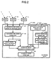
- FIG. 2 is a block diagram illustrating a calibration device according to the second embodiment of the present invention.
- the calibration device 200 according to the second embodiment includes the respective functions 101, 102, and 105 of the calibration device 100 according to the first embodiment.
- the calibration device 200 includes the database part 203 instead of the database part 103 of the calibration device 100 according to the first embodiment.
- the calibration device 200 has a calibration matrix calculation processing part (improved calibration matrix calculation processing part) 204 instead of the calibration matrix calculation processing part 104 of the calibration device 100 according to the first embodiment.
- the calibration device 200 further includes a pseudo-inverse matrix calculation processing part 206.
- the database part 203 includes an array mode vector storage part 203a that is the same as the array mode vector storage part 103a according to the first embodiment, a Fourier coefficient storage part 203b, and a pseudo-inverse matrix information storage part 203c.
- the Fourier coefficient storage part 203b stores information corresponding to the matrix F in the above Equation (8) therein in advance.
- the pseudo-inverse matrix information storage part 203c stores information corresponding to the matrix U 1 and the matrix U 2 in the above Equations (24) and (25) therein in advance. Accordingly, the database part 203 stores the information corresponding to the array mode vectors and the matrix F, and the information corresponding to the matrixes U 1 and U 2 therein in advance.
- the pseudo-inverse matrix calculation processing part 206 executes the arithmetic processing of the above Equations (22) and (23) by using the observation data vectors stored in the observation data vector storage part 102.
- the calibration matrix calculation processing part 204 executes the arithmetic processing of the above Equations (16) to (21) by using the observation data vector stored in the observation data vector storage part 102, the calculated value obtained by the pseudo-inverse matrix calculation processing part 206, and the information stored in the database part 203 to acquire the calibration matrix M(hat).
- the other components are identical with those in the first embodiment.
- the array mode vectors a( ⁇ ) and the Fourier coefficient are stored in the database part 203 in advance. Further, the orthogonal vector is calculated from the array mode vectors a( ⁇ ) and the Fourier coefficient by the calibration matrix calculation processing part 204. Asaresult, even when plural pieces of observation data are high in correlation, the orthogonal vector can be calculated with a relatively small amount of calculation.
- the calibration matrix M is divided and estimated, resulting in advantages that a matrix F 1 H and a matrix F 2 H deviated from the matrix F H have the left pseudo-inverse matrix, and the size of the matrix that conducts the inverse matrix operation in Equations (22) to (25) is smaller than the number of sensors.
- the array mode vectors a( ⁇ ) and the Fourier coefficient are stored in the database part 203 in advance.
- the present invention is not limited to this example, and at least one of the array mode vectors a( ⁇ ) and the Fourier coefficient may not be stored in the database in advance but may be sequentially calculated.
- the calibration matrix calculation processing part 204 may sequentially compute the above Equations (5) and (6). That is, the database part 203 may be omitted, and the calibration matrix calculation processing part 204 may have a function of the mode vector association processing part.
- a matrix R (bar) based on the correction matrix R is calculated through arithmetic processing of the following Equation (30) (here, R(bar) means "-" is added to a top of symbol R.).
- Information corresponding to one arbitrary column (given matrix element) in the matrix R (bar) based on the correlation matrix R is used to improve the signal-to-noise ratio of the observation data vector r.
- R ⁇ R ⁇ ⁇ N 2 I where ⁇ 2 N is a noise power. Note that, when the noise power ⁇ 2 N is estimated by the unknown parameter estimation device, the estimated value can be diverted as the noise power ⁇ 2 N .
- a definition of the information corresponding to one arbitrary column in the matrix R(bar) is based on a fact that the amount of information carried by one arbitrary column in the matrix R (bar) is equivalent to the amount of information carried by the amount of information provided to one arbitrary row. That is, even if how to use the element in the matrix R(bar) is different, the information corresponds to one arbitrary column. When the signal-to-noise ratio is sufficiently large, the noise power ⁇ 2 N can be ignored. Further, entire information may be manipulated so that a specific element of information corresponding to one arbitrary column becomes a given power.
- FIG. 3 is a block diagram illustrating a configuration of a calibration device according to the third embodiment of the present invention.
- the calibration device 300 according to the third embodiment includes the respective functions 101, 103, and 105 of the calibration device 100 according to the first embodiment.
- the calibration device 300 includes a calibration matrix calculation processing part 304 instead of the calibration matrix calculation processing part 104 of the calibration device 100 according to the first embodiment.
- the calibration device 300 has a correlation matrix processing part 307.
- the calibration device 300 includes a vector information storage part 308 instead of the observation data vector storage part 102 of the calibration device 100 according to the first embodiment.
- the correlation matrix processing part 307 executes arithmetic processing of the above Equation (29) by using the observation data vectors r generated by the observation data vector generation processing part 101 to calculate the correlation matrix R. Further, the correlation matrix processing part 307 executes the arithmetic processing of the above Equation (30), calculates the matrix R(bar) obtained by removing an influence of noise from the correlation matrix R, and extracts and outputs information corresponding one arbitrary column in the matrix R(bar) . That is, the correlation matrix processing part 307 extracts a given matrix element in the matrix R(bar).
- the vector information storage part 308 receives information corresponding to one arbitrary column in the matrix R(bar).
- the vector information storage part 308 can store plural pieces of information corresponding to one arbitrary column in the matrix R(bar).
- a calibration matrix calculation processing part 304 acquires information corresponding to one arbitrary column in the matrix R (bar) based on the correlation matrix R.
- the other functions of the calibration matrix calculation processing part 304 are identical with those of the calibration matrix calculation processing part 104 according to the first embodiment. Further, the other components of the calibration device 300 are identical with those of the calibration device 100 according to the first embodiment.
- the eigenvalue calculation operation of a matrix having a size corresponding to the number of sensors as disclosed in Non-patent Document 4 is not required, with the result that the signal-to-noise ratio of the observation data vector r can be improved by relatively simple processing.
- the third embodiment is described based on the calibration device 100 of the first embodiment.
- the present invention is not limited to this example, but the respective functions 302, 307, and 308 of the calibration device 300 according to the third embodiment may be applied to the calibration device 200 according to the second embodiment.
- the matrix operation of U 1 B 2 in the above Equation (20) can be replaced with processing (averaging processing) for calculating an average value of the respective column elements of a matrix B 2 .
- the matrix operation of U 2 B 1 in the above Equation (21) can be replaced with processing (averaging processing) of calculating an average value of the respective column elements of a matrix B 1 . Note that, those replacements can be conducted even if the sizes of the matrix U 1 and the matrix U 2 are different from each other.
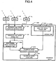
- FIG. 4 is a block diagram illustrating a calibration device 400 according to a fourth embodiment of the present invention.
- the calibration device 200 includes the respective functions 101, 102, and 105 of the calibration device 100 according to the first embodiment and the function 206 of the calibration device 200 according to the second embodiment.
- the calibration device 400 includes the database part 403 instead of the database part 203 of the calibration device 200 according to the second embodiment.
- the database part 403 includes an array mode vector storage part 403a that is similar to the array mode vector storage part 203a of the second embodiment.
- the calibration device 400 has a calibration matrix calculation processing part (averaging improvement calibration matrix calculation processing part) 404 instead of the calibration matrix calculation processing part 204 of the calibration device 200 according to the second embodiment.
- the calibration matrix calculation processing part 404 replaces the matrix operation U 1 B 2 (given element) with averaging processing of the respective column elements of the matrix B 2 to execute arithmetic processing, in the arithmetic processing based on the above Equations (16) to (21) by the calibration matrix calculation processing part 204 of the second embodiment. Together with this operation, the calibration matrix calculation processing part 404 replaces the matrix operation U 2 B 1 (given element) with averaging processing of the respective column elements of B 1 to execute arithmetic processing.
- the calibration matrix calculation processing part 404 replaces the arithmetic processing using the orthogonal vectors in the arithmetic processing of the matrix M 11 , the matrix M 12 , the matrix M 21 , and the matrix M 22 with averaging processing to execute the averaging (that is, averaging processing is executed on the respective given elements of the plurality of given matrixes).
- the calibration matrix calculation processing part 404 repetitively estimates the matrix M 11 , the matrix M 12 , the matrix M 21 , and the matrix M 22 , which have been subjected to the averaging processing, from the mutual relationship of the matrix M 11 , the matrix M 12 , the matrix M 21 , and the matrix M 22 . Thereafter, the calibration matrix calculation processing part 404 estimates the calibration matrix M (hat) by using the matrix M 11 (hat), the matrix M 12 (hat), the matrix M 21 (hat), and the matrix M 22 (hat), which have been repetitively estimated.
- the other components of the calibration device 400 are identical with those of the calibration device 100 of the first embodiment and the calibration device 200 of the second embodiment.
- the matrix operation of the orthogonal vectors in the second embodiment is replaced with averaging processing.
- the operation scale can be reduced as compared with the calibration device 200 of the second embodiment, and the manufacturing costs can be more reduced.
- the respective functions 302, 307, and 308 of the calibration device 300 according to the third embodiment can be applied to the calibration device 400 of the fourth embodiment.
- the plurality of sensors configure the array antenna.
- the plurality of sensors are not limited to the array antenna, but may be a plurality of frequency observation sensors or a plurality of polarization sensors, for example.
- the array mode vectors a( ⁇ ) in the first to fourth embodiments may be a mode vector corresponding to the characteristics of the plurality of sensors.
- the array mode vectors a( ⁇ ) are stored in the database parts 103 and 403 in advance.
- the present invention is not limited to this example, and the array mode vectors a( ⁇ ) may not be stored in the database in advance and may be sequentially calculated. That is, each of the calibration matrix calculation processing parts 104, 304, and 404 may further include a function of the mode vector association processing part. In this case, the use capacity of a storage device (ROM, etc.) that constitutes the database parts 103 and 403 can be reduced, and the device scale can be reduced.
Description
- The present invention relates to a calibration device for an unknown parameter estimation device for estimating an unknown parameter from information observed by a plurality of sensors (sensor elements), and more particularly, to a calibration device for an unknown parameter estimation device such as an angle measuring device using an array antenna, a ranging device using a sensor that observes a plurality of frequencies, and an observation device using a plurality of polarization sensors.
- In general, in a device that measures an unknown parameter of a received signal by using a plurality of sensors, it is necessary that a reception channel characteristic of each sensor is measured in advance, or that the reception characteristics of all the sensors are so calibrated as to be identical with each other. For that reason, it is necessary that observation data corresponding to the unknown parameter is observed, and the reception channel characteristic of each sensor is measured or calibrated.
- As a related art to the unknown parameter estimation device, there is a multiple signal classification (MUSIC) method (for example, refer to Non-patent Document 1). In the related art using the MUSIC method, when a plurality of signals to be observed is high in correlation, for example, processing disclosed in Non-patent Document 2 needs to be conducted in a prestage.
- Under such circumstances, in order to apply the pre-processing disclosed in Non-patent Document 2, it is necessary to use an observation device in which all of the sensors are identical in reception channel characteristic with each other, or a calibration device for calibrating the reception channel characteristics of all the sensors to be identical with each other. Because the former observation device is difficult to realize, the latter calibration device is generally used.
- Further, as a related art that realizes the calibration device, there are, for example, devices disclosed in Non-patent Document 3 and Non-patent Document 4. In those related arts, a calibration matrix is estimated, which expresses, as a matrix, a plurality of calibration parameters for making the reception characteristics of the plurality of sensors identical with each other. The document
US 2005/0185728 A1 discloses a method and a device for calibrating downlink and uplink channels by orthogonalization of transmit vectors. The documentUS 2006/0019712 A1 shows a calibration apparatus and a method for compensating phase characteristics in receiving and transmitting signal paths of an array antenna system. - Non-patent Document 1: R. O. Schmidt, "Multiple emitter location and signal parameter estimation," IEEE Trans. Antennas and Propagation, vol. AP-34, no. 3, pp. 276-280, March 1986
- Non-patent Document 2: T. Shan, M. Wax, T. Kailath, "On spatial smoothing for direction-of-arrival estimation of coherent signals, " IEEE Trans. Acoustics, Speech and Signal Processing, vol. 33, no. 4, pp. 806-811, Aug 1985
- Non-patent Document 3: B. Friedlander, A. J. Weiss, "Direction finding in the presence of mutual coupling," IEEE Trans. Antennas and Propagation, vol. 39, no. 3, pp. 273-284, March 1991
- Non-patent Document 4: C. M. S. See, "Sensor array calibration in the presence of mutual coupling and unknown sensor gains and phases, " Electronics Letters, vol. 30, pp. 373-374, March 1994
-
FIG. 5 is a block diagram illustrating a configuration of a conventional calibration device. Acalibration device 500 illustrated inFIG. 5 is the related art disclosed in Non-patent Document 3. Referring toFIG. 5 , thecalibration device 500 is connected to a plurality of (L: arbitrary number)sensors 1A to 1L. Thesensors 1A to 1L constitute, for example, an array antenna. Further, thecalibration device 500 receives observation data (signals) from the plurality ofsensors 1A to 1L. - Further, the
calibration device 500 includes an observation data vectorgeneration processing part 501, an orthogonal vectorcalculation processing part 502, an orthogonalvector storage part 503, adatabase part 504, a calibration matrixcalculation processing part 505, and a calibrationmatrix output part 506. - The observation data vector
generation processing part 501 generates an observation data vector based on observation data received from thesensors 1A to 1L. The orthogonal vectorcalculation processing part 502 receives the observation data vector from the observation data vectorgeneration processing part 501. Further, the orthogonal vectorcalculation processing part 502 calculates an orthogonal vector from the received observation data vector every time the observation data vector is received. The orthogonalvector storage part 503 can store a plurality of orthogonal vectors calculated by the orthogonal vectorcalculation processing part 502. - The
database part 504 includes an array modevector storage part 504a. The array modevector storage part 504a stores in advance a plurality of array mode vectors a(θ) in association with observation data vectors r each obtained by observing a single signal of a parameter (angle) θ and the parameters θ. - The calibration matrix
calculation processing part 505 estimates a matrix W representing an influence of an observation error from the following Equation (1) with the use of the orthogonal vectors stored in the orthogonalvector storage part 503, and the array mode vectors a(θ) stored in the array modevector storage part 504a. The reason that the matrix W is estimated as represented by Equation (1) is based on a physical characteristic of the observation error according to the disclosure of Non-patent Document 3.
[Eq. 1]
- Further, the calibration matrix
calculation processing part 505 calculates a calibration matrix M for calibrating the influence of the observation error through an inverse matrix operation of the matrix W as represented by a relationship of the following Equation (2). The calibration matrix M is a matrix made up of a plurality of calibration parameters.
[Eq. 2]
- The calibration
matrix output part 506 transmits the calibration matrix M calculated by the calibration matrixcalculation processing part 505 to an unknown parameter estimation device (not shown). The unknown parameter estimation device is, for example, an angle measuring device, a ranging device, or an observation device. - In the
conventional calibration device 500 illustrated inFIG. 5 , the orthogonal vectorcalculation processing part 502 sequentially calculates the orthogonal vector based on the observation data vector. The calibration matrixcalculation processing part 505 executes the inverse matrix operation of the matrix W to calculate the calibration matrix M. For that reason, in theconventional calibration device 500, it is necessary to execute the inverse matrix operation to a matrix of a size corresponding to the number of sensors or more, or execute an eigenvalue calculation operation a plurality of times. As a result, theconventional calibration device 500 suffers from such problems that an operation load and a device scale become relatively large, and the manufacturing costs increase. - The present invention has been made to solve the above-mentioned problems, and has an object to provide a calibration device that can suppress an increase in device scale and reduce the manufacturing costs.
- According to the present invention, there is provided a calibration device for calibrating observation data received by a plurality of sensors, the calibration device including: an observation data vector generation processing part that receives the observation data from the plurality of sensors to generate an observation data vector from the received observation data; a mode vector association processing part capable of calculating or storing in advance a mode vector corresponding to the observation data vector, and of storing an orthogonal vector in association with the mode vector; and a calibration parameter calculating part that acquires the observation data vector from the observation data vector generation processing part, acquires the orthogonal vector to the mode vector corresponding to the acquired observation data vector from the mode vector association processing part, and calculates a plurality of calibration parameters for calibrating an observation error included in the observation data vector from the acquired orthogonal vector and the observation data vector.
-
- [
FIG. 1] FIG. 1 is a block diagram illustrating a calibration device according to a first embodiment of the present invention. - [
FIG. 2] FIG. 2 is a block diagram illustrating a calibration device according to a second embodiment of the present invention. - [
FIG. 3] FIG. 3 is a block diagram illustrating a calibration device according to a third embodiment of the present invention. - [
FIG. 4] FIG. 4 is a block diagram illustrating a calibration device according to a fourth embodiment of the present invention. - [
FIG. 5] FIG. 5 is a block diagram illustrating a conventional calibration device. - Hereinafter, preferred embodiments of the present invention is described with reference to the drawings.
-
FIG. 1 is a block diagram illustrating a calibration device according to a first embodiment of the present invention. - Referring to
FIG. 1 , acalibration device 100 is connected to a plurality of (L: an arbitrary number)sensors 1A to 1L. Thesensors 1A to 1L constitute, for example, an array antenna. Further, thecalibration device 100 receives observation data (observation signals) from the plurality ofsensors 1A to 1L. - Further, the
calibration device 100 includes an observation data vectorgeneration processing part 101, an observation datavector storage part 102, adatabase part 103 as a mode vector association processing part, a calibration matrixcalculation processing part 104 as a calibration parameter calculating part, and a calibrationmatrix output part 105. The observation data vectorgeneration processing part 101 generates observation data vectors from the observation data from thesensors 1A to 1L. The observation datavector storage part 102 can store a plurality of observation data vectors received from the observation data vectorgeneration processing part 101 therein. - The
database part 103 includes an array modevector storage part 103a and an orthogonalvector storage part 103b. The array modevector storage part 103a stores in advance a plurality of array mode vectors a(θ) in association with observation data vectors r each obtained by observing a single signal of a parameter (angle) θ, and the parameters θ. The orthogonalvector storage part 103b stores orthogonal vectors to the plurality of array mode vectors a(θ) in association with the parameters θ therein in advance. Accordingly, thedatabase part 103 stores the array mode vectors a(θ) and the orthogonal vectors thereto therein in advance. - The calibration matrix
calculation processing part 104 estimates the calibration matrix M from a relationship represented by the following Equation (3) by using the orthogonal vectors stored in the orthogonalvector storage part 103b, and the array mode vectors a(θ) stored in the array modevector storage part 102.
[Eq. 3]
- The calibration
matrix output part 105 transmits the calibration matrix M calculated by the calibration matrixcalculation processing part 104 to an unknown parameter estimation device (not shown). The unknown parameter estimation device is, for example, an angle measuring device, a ranging device, or an observation device. - The
calibration device 100 can be configured by a computer (not shown) including an arithmetic processing unit (CPU), a storage device (ROM, RAM, and hard disk), and a signal input/output device. In the storage device in the computer of thecalibration device 100, there are stored programs for realizing the functions of the observation data vectorgeneration processing part 101, the observation datavector storage part 102, thedatabase part 103, the calibration matrixcalculation processing part 104, and the calibrationmatrix output part 105. - As described above, according to the
calibration device 100 of the first embodiment, the array mode vectors a(θ) are known information, and hence the orthogonal vector can be calculated in advance. For that reason, the orthogonal vectors v of the array mode vectors a(θ) are registered in the orthogonalvector storage part 103b of thedatabase part 103 in advance. As a result, unlike theconventional calibration device 500 illustrated inFIG. 5 , it is unnecessary to calculate the orthogonal vectors directly based on the observation data vectors. Accordingly, in thecalibration device 100 of the first embodiment, an increase in operation load and an increase in device scale can be suppressed, and the manufacturing costs can be reduced. - In the related art disclosed in Non-patent Document 4, the calibration matrix M is estimated directly without using the orthogonal vector. However, in this case, because a matrix of a size larger than the number of sensors L is subjected to the inverse matrix operation or the like, a relatively large amount of operation is required, resulting in a relatively increased operation load. On the contrary, in the
calibration device 100 of the first embodiment, the orthogonal vectors are stored in thedatabase part 103. For that reason, no eigenvalue calculation operation is conducted on the orthogonal vectors. As a result, as compared with the related art disclosed in Non-patent Document 4, the occurrence frequency of the eigenvalue calculation operation as theentire calibration device 100 can be reduced. - First, when a plurality of signals to be observed is high in correlation as in the related art of
Non-patent Document 1, pre-processing is conducted, for example, as disclosed in Non-patent Document 2. For that reason, the plurality of sensors may be required to have, as a condition, the same observation characteristic with respect to the parameter θ. Under such a condition, the orthogonal vector can be calculated according to the array mode vectors a(θ) and a Fourier coefficient. - In a
calibration device 200 according to a second embodiment of the present invention, the array mode vectors a(θ) and the Fourier coefficient are stored in adatabase part 203. Further, in thecalibration device 200, the array mode vectors a(θ) and the Fourier coefficient are used for calculation of the orthogonal vectors of the array mode vectors a(θ). - Subsequently, a method of calculating the orthogonal vector according to the second embodiment is described in detail. Here, as an example, a case in which the number of sensors is four is described. Three orthogonal vectors v1 (l=1, ..., 3) orthogonal to the array mode vectors a(θ) are obtained by the following Equations (4) to (6).
[Eq. 4]


- Subsequently, simultaneous equations are observation data vectors rk obtained by separately observing signals of a plurality of parameters θk (k=1, ..., K), establish, and when the orthogonal vector v1 is expressed by the array mode vector a(θ) and the vector f1, the above Equation (3) is represented by the following Equation (7). AmatrixF, amatrixA, andamatrixD, which constitute Equation (7), are represented by the following Equations (8) to (10).
[Eq. 5]


- When direct estimation of the calibration matrix M is attempted based on the above Equation (7), because a left pseudo-inverse matrix of the matrix FH is not uniquely determined, and there is inverse matrix operation with the number of sensors as dimensions, arithmetic processing becomes difficult. Therefore, when the matrix F, the matrix A, the calibration matrix M, and the matrix D, which constitute Equation (7), are divided, the following Equations (11a) to (11c) are obtained. The matrix F, the matrix A, the calibration matrix M, and the matrix D, which constitute Equations (11a) to (11c), are obtained as the following Equations (12) to (15).
[Eq. 6]


- Further, elements of the calibration matrix M are expressed by the following Equations (16) to (19) as a matrix M11, a matrix M12, a matrix M21, and a matrix M22, based on Equations (11a) to (11c). A relationship of the respective matrixes in Equations (16) to (19) satisfies the following Equations (20) to (27).
[Eq. 7]


- That is, the calibration matrix M is divided into the matrix M11, the matrix M12, the matrix M21, and the matrix M22 as a plurality of given matrixes. Further, in Equations (16) to (19), values of three matrixes in the matrix M11, the matrix M12, the matrix M21, and the matrix M22 are fixed, and one remaining matrix is estimated. The estimate operations of Equations (16) to (19) are repetitively calculated in turns. A unit matrix I is used as an initial value of the calibration matrix M in the repetitive estimation.
- Finally, the matrix M11 (hat), the matrix M12 (hat), the matrix M21 (hat), and the matrix M22 (hat), which have been repetitively estimated, are used to calculate such the following Equation (28), the calibration matrix M(hat) which is an estimated value of the calibration matrix M (here, M(hat) means that "^" is added to a top of the symbol M, and is representative of the estimated value.) . That is, the respective matrixes are repetitively estimated from a mutual relationship of the respective matrixes based on Equations (16) to (19), and the respective matrixes that are repetitively estimated are used to estimate the calibration matrix M(hat).
[Eq. 8]
-
FIG. 2 is a block diagram illustrating a calibration device according to the second embodiment of the present invention. Referring toFIG. 2 , thecalibration device 200 according to the second embodiment includes therespective functions calibration device 100 according to the first embodiment. Further, thecalibration device 200 includes thedatabase part 203 instead of thedatabase part 103 of thecalibration device 100 according to the first embodiment. Further, thecalibration device 200 has a calibration matrix calculation processing part (improved calibration matrix calculation processing part) 204 instead of the calibration matrixcalculation processing part 104 of thecalibration device 100 according to the first embodiment. Further, thecalibration device 200 further includes a pseudo-inverse matrixcalculation processing part 206. - The
database part 203 includes an array modevector storage part 203a that is the same as the array modevector storage part 103a according to the first embodiment, a Fouriercoefficient storage part 203b, and a pseudo-inverse matrixinformation storage part 203c. The Fouriercoefficient storage part 203b stores information corresponding to the matrix F in the above Equation (8) therein in advance. The pseudo-inverse matrixinformation storage part 203c stores information corresponding to the matrix U1 and the matrix U2 in the above Equations (24) and (25) therein in advance. Accordingly, thedatabase part 203 stores the information corresponding to the array mode vectors and the matrix F, and the information corresponding to the matrixes U1 and U2 therein in advance. - The pseudo-inverse matrix
calculation processing part 206 executes the arithmetic processing of the above Equations (22) and (23) by using the observation data vectors stored in the observation datavector storage part 102. The calibration matrixcalculation processing part 204 executes the arithmetic processing of the above Equations (16) to (21) by using the observation data vector stored in the observation datavector storage part 102, the calculated value obtained by the pseudo-inverse matrixcalculation processing part 206, and the information stored in thedatabase part 203 to acquire the calibration matrix M(hat). The other components are identical with those in the first embodiment. - As described above, according to the
calibration device 200 of the second embodiment, the array mode vectors a(θ) and the Fourier coefficient are stored in thedatabase part 203 in advance. Further, the orthogonal vector is calculated from the array mode vectors a(θ) and the Fourier coefficient by the calibration matrixcalculation processing part 204. Asaresult, even when plural pieces of observation data are high in correlation, the orthogonal vector can be calculated with a relatively small amount of calculation. - Further, the calibration matrix M is divided and estimated, resulting in advantages that a matrix F1 H and a matrix F2 H deviated from the matrix FH have the left pseudo-inverse matrix, and the size of the matrix that conducts the inverse matrix operation in Equations (22) to (25) is smaller than the number of sensors.
- Further, the inverse matrix operation necessary for estimating the calibration matrix M is conducted only twice with the above Equations (22) and (23), and there is no eigenvalue calculation operation. As a result, the same advantages as those of the calibration device in the first embodiment can be obtained also in the calibration device according to the second embodiment.
- In the second embodiment, the array mode vectors a(θ) and the Fourier coefficient are stored in the
database part 203 in advance. However, the present invention is not limited to this example, and at least one of the array mode vectors a(θ) and the Fourier coefficient may not be stored in the database in advance but may be sequentially calculated. In this case, the calibration matrixcalculation processing part 204 may sequentially compute the above Equations (5) and (6). That is, thedatabase part 203 may be omitted, and the calibration matrixcalculation processing part 204 may have a function of the mode vector association processing part. - First, in the related art of Non-patent Document 4, in order to improve a signal-to-noise ratio of the observation data vectors r, eigenvalue vectors corresponding to the signal components are calculated from a correlation matrix R of the observation data vectors r based on the following Equation (29). However, in the related art of Non-patent Document 4, the signal-to-noise ratio of the observation data vectors r is improved, but the eigenvalue vector is thus calculated. For that reason, in the related art of Non-patent Document 4, the eigenvalue calculation operation of the matrix having a size corresponding to the number of sensors is conducted a plurality of times, and the operation load is relatively large.
[Eq. 9]
- On the contrary, in a
calibration device 300 according to a third embodiment, a matrix R (bar) based on the correction matrix R is calculated through arithmetic processing of the following Equation (30) (here, R(bar) means "-" is added to a top of symbol R.). Information corresponding to one arbitrary column (given matrix element) in the matrix R (bar) based on the correlation matrix R is used to improve the signal-to-noise ratio of the observation data vector r.
[Eq. 10]
- In this example, a definition of the information corresponding to one arbitrary column in the matrix R(bar) is based on a fact that the amount of information carried by one arbitrary column in the matrix R (bar) is equivalent to the amount of information carried by the amount of information provided to one arbitrary row. That is, even if how to use the element in the matrix R(bar) is different, the information corresponds to one arbitrary column. When the signal-to-noise ratio is sufficiently large, the noise power σ2 N can be ignored. Further, entire information may be manipulated so that a specific element of information corresponding to one arbitrary column becomes a given power.
-
FIG. 3 is a block diagram illustrating a configuration of a calibration device according to the third embodiment of the present invention. Referring toFIG. 3 , thecalibration device 300 according to the third embodiment includes therespective functions calibration device 100 according to the first embodiment. Further, thecalibration device 300 includes a calibration matrixcalculation processing part 304 instead of the calibration matrixcalculation processing part 104 of thecalibration device 100 according to the first embodiment. Further, thecalibration device 300 has a correlationmatrix processing part 307. Further, thecalibration device 300 includes a vectorinformation storage part 308 instead of the observation datavector storage part 102 of thecalibration device 100 according to the first embodiment. - The correlation
matrix processing part 307 executes arithmetic processing of the above Equation (29) by using the observation data vectors r generated by the observation data vectorgeneration processing part 101 to calculate the correlation matrix R. Further, the correlationmatrix processing part 307 executes the arithmetic processing of the above Equation (30), calculates the matrix R(bar) obtained by removing an influence of noise from the correlation matrix R, and extracts and outputs information corresponding one arbitrary column in the matrix R(bar) . That is, the correlationmatrix processing part 307 extracts a given matrix element in the matrix R(bar). - The vector
information storage part 308 receives information corresponding to one arbitrary column in the matrix R(bar). The vectorinformation storage part 308 can store plural pieces of information corresponding to one arbitrary column in the matrix R(bar). - A calibration matrix
calculation processing part 304 acquires information corresponding to one arbitrary column in the matrix R (bar) based on the correlation matrix R. The other functions of the calibration matrixcalculation processing part 304 are identical with those of the calibration matrixcalculation processing part 104 according to the first embodiment. Further, the other components of thecalibration device 300 are identical with those of thecalibration device 100 according to the first embodiment. - As described above, according to the calibration device of the third embodiment, the eigenvalue calculation operation of a matrix having a size corresponding to the number of sensors as disclosed in Non-patent Document 4 is not required, with the result that the signal-to-noise ratio of the observation data vector r can be improved by relatively simple processing.
- The third embodiment is described based on the
calibration device 100 of the first embodiment. However, the present invention is not limited to this example, but therespective functions calibration device 300 according to the third embodiment may be applied to thecalibration device 200 according to the second embodiment. - First, in the second embodiment, the matrix U1 of Equation (24) and the matrix U2 of Equation (25) are stored in the
database part 203 in advance. Because the matrix U1 and the matrix U2 are constant matrixes, instead of storing information in adatabase part 403, the matrix U1 and the matrix U2 may be calculated in a process of the calibration matrix calculation processing by a calibration matrixcalculation processing part 404. In particular, when the sizes of the matrix U1 and the matrix U2 are equal to each other, the matrix U1 and the matrix U2 are mathematically the same value, and have the characteristics of the following Equation (31).
[Eq. 11]
- That is, the matrix operation of U1B2 in the above Equation (20) can be replaced with processing (averaging processing) for calculating an average value of the respective column elements of a matrix B2. Likewise, the matrix operation of U2B1 in the above Equation (21) can be replaced with processing (averaging processing) of calculating an average value of the respective column elements of a matrix B1. Note that, those replacements can be conducted even if the sizes of the matrix U1 and the matrix U2 are different from each other.
- Next,
FIG. 4 is a block diagram illustrating acalibration device 400 according to a fourth embodiment of the present invention. Referring toFIG. 4 , thecalibration device 200 includes therespective functions calibration device 100 according to the first embodiment and thefunction 206 of thecalibration device 200 according to the second embodiment. Further, thecalibration device 400 includes thedatabase part 403 instead of thedatabase part 203 of thecalibration device 200 according to the second embodiment. Thedatabase part 403 includes an array modevector storage part 403a that is similar to the array modevector storage part 203a of the second embodiment. - Further, the
calibration device 400 has a calibration matrix calculation processing part (averaging improvement calibration matrix calculation processing part) 404 instead of the calibration matrixcalculation processing part 204 of thecalibration device 200 according to the second embodiment. The calibration matrixcalculation processing part 404 replaces the matrix operation U1B2 (given element) with averaging processing of the respective column elements of the matrix B2 to execute arithmetic processing, in the arithmetic processing based on the above Equations (16) to (21) by the calibration matrixcalculation processing part 204 of the second embodiment. Together with this operation, the calibration matrixcalculation processing part 404 replaces the matrix operation U2B1 (given element) with averaging processing of the respective column elements of B1 to execute arithmetic processing. - That is, the calibration matrix
calculation processing part 404 replaces the arithmetic processing using the orthogonal vectors in the arithmetic processing of the matrix M11, the matrix M12, the matrix M21, and the matrix M22 with averaging processing to execute the averaging (that is, averaging processing is executed on the respective given elements of the plurality of given matrixes). - Then, the calibration matrix
calculation processing part 404 repetitively estimates the matrix M11, the matrix M12, the matrix M21, and the matrix M22, which have been subjected to the averaging processing, from the mutual relationship of the matrix M11, the matrix M12, the matrix M21, and the matrix M22. Thereafter, the calibration matrixcalculation processing part 404 estimates the calibration matrix M (hat) by using the matrix M11(hat), the matrix M12(hat), the matrix M21(hat), and the matrix M22(hat), which have been repetitively estimated. The other components of thecalibration device 400 are identical with those of thecalibration device 100 of the first embodiment and thecalibration device 200 of the second embodiment. - As described above, according to the calibration device of the fourth embodiment, the matrix operation of the orthogonal vectors in the second embodiment is replaced with averaging processing. As a result, the operation scale can be reduced as compared with the
calibration device 200 of the second embodiment, and the manufacturing costs can be more reduced. - The
respective functions calibration device 300 according to the third embodiment can be applied to thecalibration device 400 of the fourth embodiment. - Further, in the first to fourth embodiments, an example in which the plurality of sensors configure the array antenna is described. However, the plurality of sensors are not limited to the array antenna, but may be a plurality of frequency observation sensors or a plurality of polarization sensors, for example. In this case, the array mode vectors a(θ) in the first to fourth embodiments may be a mode vector corresponding to the characteristics of the plurality of sensors.
- Further, in the first, third, and fourth embodiments, the array mode vectors a(θ) are stored in the
database parts calculation processing parts database parts
Claims (3)
- A calibration device (200) for calibrating observation data received by a plurality of sensors (1A...1L), the calibration device (200) comprising:an observation data vector generation processing part (101) that receives the observation data from the plurality of sensors (1A...1L) to generate an observation data vector from the received observation data; characterized in that the calibration device further comprisesa mode vector association processing part (203) capable of calculating or storing in advance a mode vector corresponding to the observation data vector, and of calculating or storing in advance a Fourier coefficient for calculating an orthogonal vector to the mode vector; anda calibration parameter calculating part (204) that acquires the observation data vector from the observation data vector generation processing part (101), acquires the mode vector and the Fourier coefficient corresponding to the acquired observation data vector from the mode vector association processing part (203), calculates an orthogonal vector to the mode vector from the acquired mode vector and the acquired Fourier vector, and calculates a plurality of calibration parameters for calibrating an observation error included in the observation data vector from the calculated orthogonal vector and the observation data vector.
- A calibration device (200) according to claim 1,
wherein the calibration parameter calculating part (204) calculates a calibration matrix, which includes the plurality of calibration parameters and is divided into a plurality of given matrixes in advance, and
wherein the calibration parameter calculating part (204) repetitively estimates each of the plurality of given matrixes from a mutual relationship of the plurality of given matrixes, and estimates the calibration matrix by using the plurality of given matrixes which have been repetitively estimated. - A calibration device (300) according to any one of claims 1 or 2, further comprising a correlation matrix calculating part (307) that calculates a correlation matrix of a plurality of pieces of observation data received by the plurality of sensors, and extracts a given matrix element included in the calculated correlation matrix,
wherein the calibration parameter calculating part (304) corrects the observation data vector by using the given matrix element extracted by the correlation matrix calculating part (307).
Applications Claiming Priority (1)
| Application Number | Priority Date | Filing Date | Title |
|---|---|---|---|
| PCT/JP2009/052308 WO2010092673A1 (en) | 2009-02-12 | 2009-02-12 | Calibration device |
Publications (3)
| Publication Number | Publication Date |
|---|---|
| EP2398111A1 EP2398111A1 (en) | 2011-12-21 |
| EP2398111A4 EP2398111A4 (en) | 2014-08-20 |
| EP2398111B1 true EP2398111B1 (en) | 2017-09-27 |
Family
ID=42561525
Family Applications (1)
| Application Number | Title | Priority Date | Filing Date |
|---|---|---|---|
| EP09839995.9A Not-in-force EP2398111B1 (en) | 2009-02-12 | 2009-02-12 | Calibration device |
Country Status (5)
| Country | Link |
|---|---|
| US (1) | US8892383B2 (en) |
| EP (1) | EP2398111B1 (en) |
| JP (1) | JP5289467B2 (en) |
| CN (1) | CN102282722A (en) |
| WO (1) | WO2010092673A1 (en) |
Families Citing this family (5)
| Publication number | Priority date | Publication date | Assignee | Title |
|---|---|---|---|---|
| JP5701106B2 (en) * | 2011-03-04 | 2015-04-15 | 富士通テン株式会社 | Radar device and method of calculating angle of arrival of radar device |
| CN102401888B (en) * | 2011-08-24 | 2013-10-23 | 西安电子科技大学 | Method for self-correcting coupling error of electromagnetic vector sensor array |
| US20190090781A1 (en) * | 2017-09-28 | 2019-03-28 | Vital Connect, Inc. | Sensor calibration considering subject-dependent variables and/or body positions |
| FR3098667B1 (en) | 2019-07-08 | 2023-11-10 | Commissariat Energie Atomique | Method for calibrating an acoustic antenna |
| JP7472060B2 (en) | 2021-03-03 | 2024-04-22 | 株式会社日立国際電気 | Direction of Arrival Estimation System |
Family Cites Families (14)
| Publication number | Priority date | Publication date | Assignee | Title |
|---|---|---|---|---|
| US5359333A (en) * | 1993-07-21 | 1994-10-25 | E-Systems, Inc. | Robust multiple cochannel emitter detectors |
| US6184829B1 (en) * | 1999-01-08 | 2001-02-06 | Trueposition, Inc. | Calibration for wireless location system |
| US20060019712A1 (en) | 2001-11-14 | 2006-01-26 | Seung-Won Choi | Calibration apparatus for smart antenna and method thereof |
| US7206354B2 (en) | 2004-02-19 | 2007-04-17 | Qualcomm Incorporated | Calibration of downlink and uplink channel responses in a wireless MIMO communication system |
| JP4447380B2 (en) * | 2004-06-04 | 2010-04-07 | 株式会社エヌ・ティ・ティ・ドコモ | Array antenna receiver and transmitter |
| US7706324B2 (en) | 2004-07-19 | 2010-04-27 | Qualcomm Incorporated | On-demand reverse-link pilot transmission |
| JP4562542B2 (en) | 2005-02-15 | 2010-10-13 | 三洋電機株式会社 | CALIBRATION METHOD AND BASE STATION DEVICE, TERMINAL DEVICE, AND RADIO DEVICE USING THE SAME |
| JP4646680B2 (en) * | 2005-03-04 | 2011-03-09 | 三洋電機株式会社 | Calibration method and radio apparatus and communication system using the same |
| JP4646682B2 (en) | 2005-04-13 | 2011-03-09 | 三洋電機株式会社 | Calibration method and radio apparatus and communication system using the same |
| ES2795649T3 (en) | 2005-05-13 | 2020-11-24 | Qualcomm Inc | On-demand transmission of reverse link pilot signals |
| JP4356756B2 (en) * | 2006-04-27 | 2009-11-04 | ソニー株式会社 | Wireless communication system, wireless communication apparatus, and wireless communication method |
| JP4876776B2 (en) * | 2006-08-22 | 2012-02-15 | 日本電気株式会社 | Wireless transmission device and wireless reception device |
| WO2009093182A2 (en) * | 2008-01-25 | 2009-07-30 | Koninklijke Philips Electronics N.V. | A method for communicating a signal using analog beam steering, a transmitting station, a receiving station and a preamble structure therefor |
| CN101251597B (en) * | 2008-04-08 | 2011-02-09 | 西安电子科技大学 | Method for self-correction of array error of multi-input multi-output radar system |
-
2009
- 2009-02-12 US US13/132,416 patent/US8892383B2/en active Active
- 2009-02-12 EP EP09839995.9A patent/EP2398111B1/en not_active Not-in-force
- 2009-02-12 CN CN2009801544255A patent/CN102282722A/en active Pending
- 2009-02-12 WO PCT/JP2009/052308 patent/WO2010092673A1/en active Application Filing
- 2009-02-12 JP JP2010550369A patent/JP5289467B2/en active Active
Non-Patent Citations (1)
| Title |
|---|
| None * |
Also Published As
| Publication number | Publication date |
|---|---|
| CN102282722A (en) | 2011-12-14 |
| US20110238355A1 (en) | 2011-09-29 |
| EP2398111A4 (en) | 2014-08-20 |
| JP5289467B2 (en) | 2013-09-11 |
| US8892383B2 (en) | 2014-11-18 |
| WO2010092673A1 (en) | 2010-08-19 |
| JPWO2010092673A1 (en) | 2012-08-16 |
| EP2398111A1 (en) | 2011-12-21 |
Similar Documents
| Publication | Publication Date | Title |
|---|---|---|
| US11228363B2 (en) | OAM multiplexing communication system and inter-mode interference elimination method | |
| JP6685623B2 (en) | Efficient sparse channel estimation based on compressed sensing | |
| US7570211B1 (en) | Digital beamforming method and apparatus for pointing and null steering without calibration or calculation of covariance matrix | |
| EP1850147A1 (en) | Arriving correction deducing device and program | |
| EP2398111B1 (en) | Calibration device | |
| US11139867B2 (en) | Antenna displacement correction method and device for OAM multiplexing communication system | |
| He et al. | Simultaneous interference localization and array calibration for robust adaptive beamforming with partly calibrated arrays | |
| JP4977849B2 (en) | Radio wave arrival direction detector | |
| WO2017008307A1 (en) | Method and apparatus for performing beamforming | |
| EP3360265B1 (en) | Channel condition estimation | |
| JP6694321B2 (en) | Reception quality measuring device and program | |
| CN105548952A (en) | Common-frequency multi-signal direction-finding method based on blind source separation | |
| JP5579569B2 (en) | Propagation parameter estimation device and propagation parameter estimation method | |
| US11256780B1 (en) | Methods and apparatus for fast eigenvalue decomposition of Hermitian matrices | |
| US20230031343A1 (en) | Method and system for estimating a quantity representative of sound energy | |
| US10224998B2 (en) | Receive decorrelator for a wireless communications system | |
| JP4576742B2 (en) | Transmission / reception frequency division multiplexing radio equipment | |
| JP2012215444A (en) | Direction measurement device; and direction measurement method and direction measurement program used for direction measurement device | |
| CN110912600B (en) | Communication method, device, equipment and storage medium | |
| JP4060001B2 (en) | Angle measuring device and angle measuring method | |
| JP4959228B2 (en) | Arrival wave number estimation device | |
| KR20110112048A (en) | Method and apparatus for detection of mimo antenna characteristics and performance | |
| Elbir et al. | Direction finding and localization for far-field sources with near-field multipath reflections | |
| JP2022134449A (en) | Arrival direction estimation system | |
| JP4411234B2 (en) | Radio apparatus and beam pattern control method |
Legal Events
| Date | Code | Title | Description |
|---|---|---|---|
| PUAI | Public reference made under article 153(3) epc to a published international application that has entered the european phase |
Free format text: ORIGINAL CODE: 0009012 |
|
| 17P | Request for examination filed |
Effective date: 20110608 |
|
| AK | Designated contracting states |
Kind code of ref document: A1 Designated state(s): AT BE BG CH CY CZ DE DK EE ES FI FR GB GR HR HU IE IS IT LI LT LU LV MC MK MT NL NO PL PT RO SE SI SK TR |
|
| DAX | Request for extension of the european patent (deleted) | ||
| A4 | Supplementary search report drawn up and despatched |
Effective date: 20140723 |
|
| RIC1 | Information provided on ipc code assigned before grant |
Ipc: H01Q 3/26 20060101AFI20140717BHEP Ipc: H04B 17/00 20060101ALI20140717BHEP |
|
| GRAP | Despatch of communication of intention to grant a patent |
Free format text: ORIGINAL CODE: EPIDOSNIGR1 |
|
| GRAJ | Information related to disapproval of communication of intention to grant by the applicant or resumption of examination proceedings by the epo deleted |
Free format text: ORIGINAL CODE: EPIDOSDIGR1 |
|
| GRAP | Despatch of communication of intention to grant a patent |
Free format text: ORIGINAL CODE: EPIDOSNIGR1 |
|
| INTG | Intention to grant announced |
Effective date: 20170405 |
|
| INTG | Intention to grant announced |
Effective date: 20170413 |
|
| GRAS | Grant fee paid |
Free format text: ORIGINAL CODE: EPIDOSNIGR3 |
|
| GRAA | (expected) grant |
Free format text: ORIGINAL CODE: 0009210 |
|
| AK | Designated contracting states |
Kind code of ref document: B1 Designated state(s): AT BE BG CH CY CZ DE DK EE ES FI FR GB GR HR HU IE IS IT LI LT LU LV MC MK MT NL NO PL PT RO SE SI SK TR |
|
| REG | Reference to a national code |
Ref country code: GB Ref legal event code: FG4D |
|
| REG | Reference to a national code |
Ref country code: CH Ref legal event code: EP |
|
| REG | Reference to a national code |
Ref country code: AT Ref legal event code: REF Ref document number: 932817 Country of ref document: AT Kind code of ref document: T Effective date: 20171015 |
|
| REG | Reference to a national code |
Ref country code: IE Ref legal event code: FG4D |
|
| REG | Reference to a national code |
Ref country code: DE Ref legal event code: R096 Ref document number: 602009048626 Country of ref document: DE |
|
| PG25 | Lapsed in a contracting state [announced via postgrant information from national office to epo] |
Ref country code: NO Free format text: LAPSE BECAUSE OF FAILURE TO SUBMIT A TRANSLATION OF THE DESCRIPTION OR TO PAY THE FEE WITHIN THE PRESCRIBED TIME-LIMIT Effective date: 20171227 Ref country code: LT Free format text: LAPSE BECAUSE OF FAILURE TO SUBMIT A TRANSLATION OF THE DESCRIPTION OR TO PAY THE FEE WITHIN THE PRESCRIBED TIME-LIMIT Effective date: 20170927 Ref country code: HR Free format text: LAPSE BECAUSE OF FAILURE TO SUBMIT A TRANSLATION OF THE DESCRIPTION OR TO PAY THE FEE WITHIN THE PRESCRIBED TIME-LIMIT Effective date: 20170927 Ref country code: FI Free format text: LAPSE BECAUSE OF FAILURE TO SUBMIT A TRANSLATION OF THE DESCRIPTION OR TO PAY THE FEE WITHIN THE PRESCRIBED TIME-LIMIT Effective date: 20170927 Ref country code: SE Free format text: LAPSE BECAUSE OF FAILURE TO SUBMIT A TRANSLATION OF THE DESCRIPTION OR TO PAY THE FEE WITHIN THE PRESCRIBED TIME-LIMIT Effective date: 20170927 |
|
| REG | Reference to a national code |
Ref country code: NL Ref legal event code: MP Effective date: 20170927 |
|
| REG | Reference to a national code |
Ref country code: LT Ref legal event code: MG4D |
|
| REG | Reference to a national code |
Ref country code: AT Ref legal event code: MK05 Ref document number: 932817 Country of ref document: AT Kind code of ref document: T Effective date: 20170927 |
|
| PG25 | Lapsed in a contracting state [announced via postgrant information from national office to epo] |
Ref country code: LV Free format text: LAPSE BECAUSE OF FAILURE TO SUBMIT A TRANSLATION OF THE DESCRIPTION OR TO PAY THE FEE WITHIN THE PRESCRIBED TIME-LIMIT Effective date: 20170927 Ref country code: BG Free format text: LAPSE BECAUSE OF FAILURE TO SUBMIT A TRANSLATION OF THE DESCRIPTION OR TO PAY THE FEE WITHIN THE PRESCRIBED TIME-LIMIT Effective date: 20171227 Ref country code: GR Free format text: LAPSE BECAUSE OF FAILURE TO SUBMIT A TRANSLATION OF THE DESCRIPTION OR TO PAY THE FEE WITHIN THE PRESCRIBED TIME-LIMIT Effective date: 20171228 |
|
| PG25 | Lapsed in a contracting state [announced via postgrant information from national office to epo] |
Ref country code: NL Free format text: LAPSE BECAUSE OF FAILURE TO SUBMIT A TRANSLATION OF THE DESCRIPTION OR TO PAY THE FEE WITHIN THE PRESCRIBED TIME-LIMIT Effective date: 20170927 |
|
| PG25 | Lapsed in a contracting state [announced via postgrant information from national office to epo] |
Ref country code: RO Free format text: LAPSE BECAUSE OF FAILURE TO SUBMIT A TRANSLATION OF THE DESCRIPTION OR TO PAY THE FEE WITHIN THE PRESCRIBED TIME-LIMIT Effective date: 20170927 Ref country code: CZ Free format text: LAPSE BECAUSE OF FAILURE TO SUBMIT A TRANSLATION OF THE DESCRIPTION OR TO PAY THE FEE WITHIN THE PRESCRIBED TIME-LIMIT Effective date: 20170927 Ref country code: ES Free format text: LAPSE BECAUSE OF FAILURE TO SUBMIT A TRANSLATION OF THE DESCRIPTION OR TO PAY THE FEE WITHIN THE PRESCRIBED TIME-LIMIT Effective date: 20170927 |
|
| PG25 | Lapsed in a contracting state [announced via postgrant information from national office to epo] |
Ref country code: IT Free format text: LAPSE BECAUSE OF FAILURE TO SUBMIT A TRANSLATION OF THE DESCRIPTION OR TO PAY THE FEE WITHIN THE PRESCRIBED TIME-LIMIT Effective date: 20170927 Ref country code: SK Free format text: LAPSE BECAUSE OF FAILURE TO SUBMIT A TRANSLATION OF THE DESCRIPTION OR TO PAY THE FEE WITHIN THE PRESCRIBED TIME-LIMIT Effective date: 20170927 Ref country code: IS Free format text: LAPSE BECAUSE OF FAILURE TO SUBMIT A TRANSLATION OF THE DESCRIPTION OR TO PAY THE FEE WITHIN THE PRESCRIBED TIME-LIMIT Effective date: 20180127 Ref country code: EE Free format text: LAPSE BECAUSE OF FAILURE TO SUBMIT A TRANSLATION OF THE DESCRIPTION OR TO PAY THE FEE WITHIN THE PRESCRIBED TIME-LIMIT Effective date: 20170927 Ref country code: AT Free format text: LAPSE BECAUSE OF FAILURE TO SUBMIT A TRANSLATION OF THE DESCRIPTION OR TO PAY THE FEE WITHIN THE PRESCRIBED TIME-LIMIT Effective date: 20170927 |
|
| REG | Reference to a national code |
Ref country code: DE Ref legal event code: R097 Ref document number: 602009048626 Country of ref document: DE |
|
| PG25 | Lapsed in a contracting state [announced via postgrant information from national office to epo] |
Ref country code: DK Free format text: LAPSE BECAUSE OF FAILURE TO SUBMIT A TRANSLATION OF THE DESCRIPTION OR TO PAY THE FEE WITHIN THE PRESCRIBED TIME-LIMIT Effective date: 20170927 |
|
| PLBE | No opposition filed within time limit |
Free format text: ORIGINAL CODE: 0009261 |
|
| STAA | Information on the status of an ep patent application or granted ep patent |
Free format text: STATUS: NO OPPOSITION FILED WITHIN TIME LIMIT |
|
| PG25 | Lapsed in a contracting state [announced via postgrant information from national office to epo] |
Ref country code: PL Free format text: LAPSE BECAUSE OF FAILURE TO SUBMIT A TRANSLATION OF THE DESCRIPTION OR TO PAY THE FEE WITHIN THE PRESCRIBED TIME-LIMIT Effective date: 20170927 |
|
| 26N | No opposition filed |
Effective date: 20180628 |
|
| REG | Reference to a national code |
Ref country code: CH Ref legal event code: PL |
|
| PG25 | Lapsed in a contracting state [announced via postgrant information from national office to epo] |
Ref country code: MC Free format text: LAPSE BECAUSE OF FAILURE TO SUBMIT A TRANSLATION OF THE DESCRIPTION OR TO PAY THE FEE WITHIN THE PRESCRIBED TIME-LIMIT Effective date: 20170927 |
|
| GBPC | Gb: european patent ceased through non-payment of renewal fee |
Effective date: 20180212 |
|
| REG | Reference to a national code |
Ref country code: IE Ref legal event code: MM4A |
|
| REG | Reference to a national code |
Ref country code: BE Ref legal event code: MM Effective date: 20180228 |
|
| PG25 | Lapsed in a contracting state [announced via postgrant information from national office to epo] |
Ref country code: SI Free format text: LAPSE BECAUSE OF FAILURE TO SUBMIT A TRANSLATION OF THE DESCRIPTION OR TO PAY THE FEE WITHIN THE PRESCRIBED TIME-LIMIT Effective date: 20170927 Ref country code: CH Free format text: LAPSE BECAUSE OF NON-PAYMENT OF DUE FEES Effective date: 20180228 Ref country code: LU Free format text: LAPSE BECAUSE OF NON-PAYMENT OF DUE FEES Effective date: 20180212 Ref country code: LI Free format text: LAPSE BECAUSE OF NON-PAYMENT OF DUE FEES Effective date: 20180228 |
|
| REG | Reference to a national code |
Ref country code: FR Ref legal event code: ST Effective date: 20181031 |
|
| PG25 | Lapsed in a contracting state [announced via postgrant information from national office to epo] |
Ref country code: IE Free format text: LAPSE BECAUSE OF NON-PAYMENT OF DUE FEES Effective date: 20180212 |
|
| PG25 | Lapsed in a contracting state [announced via postgrant information from national office to epo] |
Ref country code: BE Free format text: LAPSE BECAUSE OF NON-PAYMENT OF DUE FEES Effective date: 20180228 Ref country code: FR Free format text: LAPSE BECAUSE OF NON-PAYMENT OF DUE FEES Effective date: 20180228 Ref country code: GB Free format text: LAPSE BECAUSE OF NON-PAYMENT OF DUE FEES Effective date: 20180212 |
|
| PG25 | Lapsed in a contracting state [announced via postgrant information from national office to epo] |
Ref country code: MT Free format text: LAPSE BECAUSE OF NON-PAYMENT OF DUE FEES Effective date: 20180212 |
|
| PG25 | Lapsed in a contracting state [announced via postgrant information from national office to epo] |
Ref country code: TR Free format text: LAPSE BECAUSE OF FAILURE TO SUBMIT A TRANSLATION OF THE DESCRIPTION OR TO PAY THE FEE WITHIN THE PRESCRIBED TIME-LIMIT Effective date: 20170927 |
|
| PG25 | Lapsed in a contracting state [announced via postgrant information from national office to epo] |
Ref country code: PT Free format text: LAPSE BECAUSE OF FAILURE TO SUBMIT A TRANSLATION OF THE DESCRIPTION OR TO PAY THE FEE WITHIN THE PRESCRIBED TIME-LIMIT Effective date: 20170927 Ref country code: HU Free format text: LAPSE BECAUSE OF FAILURE TO SUBMIT A TRANSLATION OF THE DESCRIPTION OR TO PAY THE FEE WITHIN THE PRESCRIBED TIME-LIMIT; INVALID AB INITIO Effective date: 20090212 |
|
| PG25 | Lapsed in a contracting state [announced via postgrant information from national office to epo] |
Ref country code: CY Free format text: LAPSE BECAUSE OF FAILURE TO SUBMIT A TRANSLATION OF THE DESCRIPTION OR TO PAY THE FEE WITHIN THE PRESCRIBED TIME-LIMIT Effective date: 20170927 Ref country code: MK Free format text: LAPSE BECAUSE OF NON-PAYMENT OF DUE FEES Effective date: 20170927 |
|
| PGFP | Annual fee paid to national office [announced via postgrant information from national office to epo] |
Ref country code: DE Payment date: 20211230 Year of fee payment: 14 |
|
| REG | Reference to a national code |
Ref country code: DE Ref legal event code: R119 Ref document number: 602009048626 Country of ref document: DE |
|
| PG25 | Lapsed in a contracting state [announced via postgrant information from national office to epo] |
Ref country code: DE Free format text: LAPSE BECAUSE OF NON-PAYMENT OF DUE FEES Effective date: 20230901 |