EP1717911A2 - Lamp, operating device, bus bar, circuit arrangement and bus bar adapter - Google Patents
Lamp, operating device, bus bar, circuit arrangement and bus bar adapter Download PDFInfo
- Publication number
- EP1717911A2 EP1717911A2 EP06007916A EP06007916A EP1717911A2 EP 1717911 A2 EP1717911 A2 EP 1717911A2 EP 06007916 A EP06007916 A EP 06007916A EP 06007916 A EP06007916 A EP 06007916A EP 1717911 A2 EP1717911 A2 EP 1717911A2
- Authority
- EP
- European Patent Office
- Prior art keywords
- busbar
- fuse
- luminaire
- voltage
- operating device
- Prior art date
- Legal status (The legal status is an assumption and is not a legal conclusion. Google has not performed a legal analysis and makes no representation as to the accuracy of the status listed.)
- Granted
Links
Images


Classifications
-
- H—ELECTRICITY
- H01—ELECTRIC ELEMENTS
- H01R—ELECTRICALLY-CONDUCTIVE CONNECTIONS; STRUCTURAL ASSOCIATIONS OF A PLURALITY OF MUTUALLY-INSULATED ELECTRICAL CONNECTING ELEMENTS; COUPLING DEVICES; CURRENT COLLECTORS
- H01R33/00—Coupling devices specially adapted for supporting apparatus and having one part acting as a holder providing support and electrical connection via a counterpart which is structurally associated with the apparatus, e.g. lamp holders; Separate parts thereof
- H01R33/945—Holders with built-in electrical component
- H01R33/955—Holders with built-in electrical component with switch operated manually and independent of engagement or disengagement of coupling
-
- H—ELECTRICITY
- H01—ELECTRIC ELEMENTS
- H01R—ELECTRICALLY-CONDUCTIVE CONNECTIONS; STRUCTURAL ASSOCIATIONS OF A PLURALITY OF MUTUALLY-INSULATED ELECTRICAL CONNECTING ELEMENTS; COUPLING DEVICES; CURRENT COLLECTORS
- H01R25/00—Coupling parts adapted for simultaneous co-operation with two or more identical counterparts, e.g. for distributing energy to two or more circuits
- H01R25/14—Rails or bus-bars constructed so that the counterparts can be connected thereto at any point along their length
- H01R25/142—Their counterparts
-
- H—ELECTRICITY
- H01—ELECTRIC ELEMENTS
- H01R—ELECTRICALLY-CONDUCTIVE CONNECTIONS; STRUCTURAL ASSOCIATIONS OF A PLURALITY OF MUTUALLY-INSULATED ELECTRICAL CONNECTING ELEMENTS; COUPLING DEVICES; CURRENT COLLECTORS
- H01R33/00—Coupling devices specially adapted for supporting apparatus and having one part acting as a holder providing support and electrical connection via a counterpart which is structurally associated with the apparatus, e.g. lamp holders; Separate parts thereof
- H01R33/945—Holders with built-in electrical component
- H01R33/95—Holders with built-in electrical component with fuse; with thermal switch
-
- H—ELECTRICITY
- H01—ELECTRIC ELEMENTS
- H01R—ELECTRICALLY-CONDUCTIVE CONNECTIONS; STRUCTURAL ASSOCIATIONS OF A PLURALITY OF MUTUALLY-INSULATED ELECTRICAL CONNECTING ELEMENTS; COUPLING DEVICES; CURRENT COLLECTORS
- H01R13/00—Details of coupling devices of the kinds covered by groups H01R12/70 or H01R24/00 - H01R33/00
- H01R13/44—Means for preventing access to live contacts
- H01R13/447—Shutter or cover plate
Definitions
- the invention initially relates to a luminaire according to the preamble of claim 1.
- Such lights are known and widely used. They have also been manufactured by the Applicant for decades.
- the bulbs are connected to power supply lines that provide the supply or operating voltage for the bulbs.
- the lamp has three electronic ballasts, so that the three bulbs are individually controlled.
- the ballast may for example be a working according to the DALI protocol ballast, which is individually addressable and connected to a signal line.
- the luminaire can be integrated into a network of luminaires and receive control information via the signal line via a central control. For example, the information may be transmitted from the central controller to one of the lamps of the luminaire to enter a certain dimming state, e.g. also for the purpose of color mixing, to flash, to turn on, to turn off or the like.
- the power supply line which usually includes a phase conductor and a neutral conductor, is typically connected to the luminaire via a first connection and transmits, for example, an operating voltage AC of 230 V or 110 V.
- a second connection For connecting the signal line to the luminaire or to the Luminaire associated operating device, so for example the electronic ballast, a second connection provided.
- the signal line is typically one two-core cable, via which voltages up to 25 V, for example, are transmitted.
- the signal line is normally laid separately from the power supply lines.
- the object of the invention is to provide a lamp that offers greater security against assembly errors.
- the invention solves this problem with the features of claim 1, in particular with those of the characterizing part, and is accordingly characterized in that the second connection is associated with a fuse against overvoltage, which is formed exchangeable or switchable.
- the principle of the invention thus consists essentially in providing a fuse which can be triggered when a nominal voltage is exceeded. If there is a faulty mounting, that is to say a faulty connection of the lines, so that the significantly higher operating voltage is inadvertently applied to the second connection for the signal line, the fuse can be tripped. If the fuse is advantageously designed as a fuse, the melted thread can melt as a result of heating and thus protect the downstream of the fuse arranged light or the operating device of the lamp and the electronics located there against overvoltage by interrupting the circuit.
- the fuse is interchangeable in the event of destructive tripping, such as a fuse.
- a fuse is advantageously arranged at an easily accessible location of the lamp and can be supported, for example, by conventional spring clips and replaced after release by a new fuse.
- the fuse may also be designed to be switchable, so that it triggers automatically upon detection of a nominal voltage exceeding overvoltage, and subsequently either manually switched from its tripped, the power line interrupting state in a current-conducting state or automatically switches back, for example, after a certain period of time.
- the fuse triggers very quickly and safely and permanently disconnects even high voltages of up to 400 V in the tripped state.
- This high breakdown strength of the tripped fuse is required in the event that instead of two signal lines, two phase conductors of different potential are connected to the second terminal.
- the fuse when the lamp is to be connected to a power rail.
- the fuse can safely trip in the event of faulty mounting and a faulty assignment of the conductor in the busbar and protect the lamp or the operating device of the lamp.
- the arrangement of the replaceable fuse or a manually switchable fuse in an easily accessible place mean that only a housing part of the lamp or an operating device of the lamp must be removed, wherein After removal of the housing part, for example, a mounting device for the fuse is accessible, so that the fuse can be removed and replaced by a new fuse.
- the lamp is associated with a control gear on which the first and / or the second terminal is arranged.
- the operating device of the lamp for example, an electronic ballast, a transformer or another
- the lamp directly associated device is referred to, with which the function of the lamp is controlled.
- the operating device is typically arranged directly next to the luminaire and may be located, for example, in the housing of the luminaire or in a separate operating device housing. In the event that the lamp is connected via a busbar adapter to the busbar, the operating device may also be located within a housing of the busbar adapter.
- two inputs for signal lines are assigned to the second terminal, which are short-circuited with each other via an electronic component, in particular via a varistor, that causes a large current flow through the fuse when a desired voltage between the two inputs is exceeded becomes. This current flow can trigger the fuse.
- the electronic component While at lower voltages, so in the case of a proper connection, the electronic component practically does not appear, for example, because its electrical resistance is very high, so that flows through the electronic component normally no current, can exceed a target voltage , namely, in the case of a faulty mounting, through the electronic component through a current flow, because due to the large voltage, for example, above a threshold voltage of 60 V, the electrical resistance through the Component through reduced.
- a target voltage namely, in the case of a faulty mounting
- Such a per se known device is for example a varistor (variable resistor).
- the fuse is triggered only above a voltage of 30 V or 50 V, in particular above 230 V, further in particular above 300V.
- This embodiment of the invention initially takes into account that the control information transmitted via the signal line as signals typically have only lower voltages of less than 30 V, but in any case of less than 230 V.
- voltage amplitudes of more than 400 V may occur, so that the fuse and the varistor must be designed accordingly.
- the voltage above which the fuse is triggered should, according to the invention, be selected such that it exceeds the voltage used to transmit the control information plus a certain surcharge to compensate for tolerances, for example, on the order of a few volts or a few tens of volts.
- control information corresponds to the DALI protocol (Digital Addressable Lighting Interface).
- DALI Digital Addressable Lighting Interface
- This protocol which was developed by the DALI working group at the Central Association of the German Electrical Engineering and Electronics Industry (ZVEI), is, for example, described in detail in the pre-published Handbook DALI of DALI AG, 2nd edition, 2001, publisher Richard Pflaum Verlag Münch en, described.
- the invention further relates to an operating device for a luminaire, in particular an electronic ballast, according to the preamble of claim 6.
- Such an operating device may be part of a lamp or separately from the lamp, preferably immediately adjacent to the lamp, arranged.
- electronic ballasts are also other devices for a lamp as operating equipment into consideration, with which the lamp can be dimmed, switched on or off or with which the radiation behavior or the color of the lamp can be influenced in any other way or a light source of the lamp can be addressed ,
- a control gear of the prior art typically has a first terminal for connection to a power supply line, with which the supply voltage for the operation of a light source of the lamp is transmitted.
- the operating device furthermore has a second connection for a signal line, with which control information for controlling the luminaire is transmitted.
- the control information may be formed, for example, according to the DALI protocol.
- An output of the operating device is typically connected to the lighting means, so that depending on the control information or control commands received, the operating device can perform a corresponding control of the lighting means or of the lighting means.
- the object of the invention is to develop the well-known by public prior use operating device of the preamble of claim 6 such that a greater security against assembly errors is achieved.
- the invention solves this problem with the features of claim 6, in particular with those of the characterizing part, and is accordingly characterized in that the second terminal is associated with a fuse against overvoltage, which is formed exchangeable or switchable.
- the fuse corresponds to the fuse previously described in connection with a lamp. This is again designed exchangeable or switchable.
- the fuse can be incorporated directly into the operating device or upstream of the operating device.
- the invention relates to a busbar according to the preamble of claim 10.
- Such a busbar is for example from the DE 100 25 646 A1 known.
- the known busbar has power supply lines (standard phases 1, 2 and 3), ie phase conductors, which serve to supply a lamp with operating voltage.
- the known busbar and control lines which can serve for light control and thus represent signal lines in the sense of the preamble of claim 10, can be passed through the control information to the light.
- the luminaire has a first connection, via which it can be connected to the phase conductor of the busbar, and via at least one second connection, by means of which it can be connected to the signal line of the busbar.
- the two connections on the luminaire correspond to tapping points in the conductor rails of the busbar.
- the luminaire may in turn have an operating device which, as a result of receiving control information, can control the luminous means accordingly.
- the operating device may also only be associated with the two terminals of the luminaire.
- the object of the invention is to further develop a busbar according to the preamble of claim 10 such that it better protects the lamp or a control gear for the lamp against consequences of incorrect installation or misconnection to the busbar.
- the invention solves this problem with the features of claim 10, in particular with those of the characterizing part, and is accordingly characterized in that the second terminal is assigned a fuse against overvoltage, which is designed to be interchangeable or switchable.
- An essential advantage of the busbar according to the invention is that a conventional busbar, which has, for example, three phase conductors and a neutral conductor, now also a luminaire, which receives control information via a signal line, can be connected without causing assembly errors serious consequences.
- the arrangement of a fuse against overvoltage which is designed to be interchangeable or switchable, allows protection of the high-quality equipment or the lamp in the event of overvoltage due to a mounting error. By replacing the fuse or by switching back the fuse from the tripped state in a state of rest in which it passes, the operability of the lamp or the operating device can be restored after a great effort to correct installation.
- the fuse can be arranged, for example, on the busbar or od directly or indirectly fixed to an adapter. The like. Be arranged, which is attached to the power rail.
- the invention further relates to a circuit arrangement according to the preamble of claim 14.
- the object of this invention is a circuit arrangement for a lamp or for a control gear or to design for a busbar less prone to incorrect assembly.
- the invention solves this problem with the features of claim 14, in particular with those of the characterizing part, and is accordingly characterized in that the second connection is associated with a fuse against overvoltage, which is formed exchangeable or switchable.
- the circuit arrangement according to the invention can also be produced separately from a luminaire or an operating device or a busbar and connected as a separate component to a lamp or to a control gear or to a power rail.
- the invention further relates to a busbar according to the preamble of claim 18.
- the known busbar is manufactured, for example, under the name 3-phase busbar for decades by the applicant. It typically comprises three phase conductors and a neutral conductor, via which one or more lamps can be supplied with operating voltage.
- a busbar adapter is typically used in the formed in the manner of a U-profile busbar and mechanically and electrically locked to the busbar.
- the different phase conductors can optionally be contacted to the lamp, for example to connect to a group of luminaires, which can be controlled as lighting group.
- the object of the invention is to develop the known busbar such that the control of the lights is simplified.
- the invention solves this problem with the features of claim 18, in particular with those of the characterizing part, and is accordingly characterized in that a circuit is provided which is one of the two. Conductor as signal line for supplying the luminaire with control information switches.
- the principle of the invention consists essentially in a conventional busbar, e.g. a 3-phase busbar to be connected by a circuit such that one or more of the existing conductors, preferably two conductors, are used in a conventional manner to power the luminaire, wherein at least one, advantageously two, of the existing conductors, in a novel way Signal line to supply the lamp with control information can be used.
- a conventional busbar e.g. a 3-phase busbar to be connected by a circuit such that one or more of the existing conductors, preferably two conductors, are used in a conventional manner to power the luminaire, wherein at least one, advantageously two, of the existing conductors, in a novel way Signal line to supply the lamp with control information can be used.
- the newly provided circuit may preferably comprise a circuit part connecting one end of the bus bar to a central controller for a network of lights.
- the invention makes it possible to use existing busbar systems, which need only be connected in a different way than the conventional one, the busbar not having three phase conductors and a neutral, but a neutral conductor, a phase conductor and a control unit of the DALI network or another Network is connected.
- a marking element is arranged on the busbar, which indicates that one of the conductors is used for the transmission of control information.
- the marking element can further advantageously be detachably fastened to the busbar, so that it can be used as an additional element or accessory. Further advantageously, the marking element is clipped to the busbar, so that without special aids a mounting of the marking element can be made on the busbar.
- the invention relates to a busbar adapter according to the preamble of claim 25.
- busbar adapter is for example from the DE 103 12 012 A1 the applicant, to which reference is made for the purpose of avoiding repetition hereof and the content of which is hereby included for the purpose of recourse to individual features or groups of features in the content of the present patent application.
- the known busbar adapter serves for the mechanical and electrical connection of a lamp with a busbar.
- the adapter if an operating device is present, and the mechanical and electrical connection of the operating device, and possibly also at the same time also serve the light with the busbar.
- the housing of the busbar adapter can also be incorporated, for example, the operating device with.
- the known busbar adapter of the applicant comes in an advantageous manner already with a very small number of components and allows a particularly simple installation.
- the known busbar adapter has for this purpose a first and a second switching shaft, on the one hand via a phase conductor contact tongue and on the other hand have a neutral contact tongue, with which the conductor rails in the busbar are contacted.
- the object of this invention is to develop a busbar adapter according to the preamble of claim 1 such that in a simple design, a light having a first terminal for connection to a power supply line and a second terminal for connection a signal line, with the busbar is connectable.
- each switching shaft has two rotatably connected to the switching shaft contact elements.
- the principle of the invention consists essentially in assigning two switching elements each two contact elements. All contact elements can be accommodated by skillful arrangement despite the very tight space in the switching shafts.
- Each contact element has a plug-in element, preferably a tongue.
- the plug element can be connected to a connection conductor which has a mating plug element.
- the mating plug element may for example be a flat plug sleeve.
- the plug element preferably each plug element, is arranged in the vicinity of the pivot axis of the switching shaft.
- each switching shaft is assigned in each case two contact elements, the conventional construction of the in the DE 103 12 012 A1 recourse to the adapter described.
- Each switching shaft has an axis of rotation, which is aligned in the assembled state substantially perpendicular to the longitudinal extent of the busbar.
- the actuating surfaces for carrying out a rotational movement of the respective shift shaft are accordingly located outside the interior of the bus bar and allow a comfortable attack by a user, with the ability to transmit large torques.
- the Actuating surfaces arranged on a widened axial portion of the respective shift shaft or on a separate operating lever.
- the busbar adapter has a common outlet for all four or more connection conductors.
- a switching shaft on which two contact elements are arranged, has a passage for at least two further connecting conductors, wherein these two connecting conductors contact the plug-in elements of the contact elements of the respective other switching shaft.
- the plug-in elements of a switching shaft for example the switching shaft, which has the contact elements for contacting the signal lines, executed in the assembled state of the bus bar adapter to the bottom of the busbar are, whereas the plug-in elements of the contact elements of the other switching shaft are directed away from the bottom of the busbar.
- the mounting of the busbar adapter can be done in a simple manner.
- the busbar adapter can be manufactured with only a very small number of components.
- the fact that an arrangement of two contact elements on a switching shaft is possible despite the tight contact conditions in the switching shaft due to the predetermined by the insertion slot in the busbar dimensions is surprising.
- the two contact elements are each separated by a plastic or other electrically insulating material.
- the luminaire 10 comprises in a conventional construction a housing 11, in the interior 12 of which a luminous means 13 is fixedly arranged.
- the light source for example an incandescent lamp
- the leads connect the lighting means 13 with a schematically indicated operating device 15 for the lighting means, for example in the manner of an electronic ballast.
- the electronic ballast 15 has, in addition to the output 16 for connecting the supply lines 14a and 14b, a first connection 17 for connection to power supply lines 19a and 19b and a second connection 18 for connecting the operating device 15 and thus the light 10 with signal lines 20a and 20b.
- the second terminal 18 thus belongs both to the operating device 15 and to the lamp 10.
- Fig. 3 lamp corresponds to the basic structure of the prior art, however, contains a replaceable fuse explained below.
- the luminaire 10 according to the invention or the operating device 15 according to the invention can also have a plurality of first connections 17 and a plurality of second connections 18.
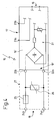
- Fig. 4 shows a schematic block diagram of a conventional operating device 15 ', in the manner of an electronic Ballast, which supplemented by an indicated circuit 21 can be used as inventive operating device 15 in the lamp 10 of FIG. 3 application.
- the operating device designated 15 'in FIG. 4 is thus a prior art operating device which has an output 16 for the supply lines 14a, 14b to the lighting device 13, a first connection 17 with two connection points 23a and 23b for connection to the voltage supply lines 19a and 19b and a second terminal 18 'with two connection points 22a and 22b, which serve in the conventional operating device 15' for connection to the signal lines 20a and 20b.
- the connection points 22a, 22b thus represent the inputs of a conventional electronic ballast 15 '.
- the signal lines 20a and 20b are connected in the luminaire 10 according to the invention or in an operating device 15 according to the invention.
- the connection points 24a and 24b only the lower voltage that transmits the control information to.
- the connection points 22a and 22b is correspondingly only the lower voltage.
- connection points 24a and 24b If, as a result of a faulty assembly whose possible occurrence will be discussed below, a higher voltage is applied to the connection points 24a and 24b, for example the operating voltage transmitted by the voltage supply lines 19a and 19b is, for example, equal to e.g. 230 V or in the case of a faulty connection to two phase conductors, a voltage in the order of 400 V, the normally a current flow between the connection points 22a and 22b blocking varistor 26 can switch to a conductive state. Namely, a varistor 26 has the peculiarity that it is not current-conducting below a threshold voltage and becomes current-conducting above a threshold voltage. If the threshold voltage is chosen, e.g.
- the voltage range for transmitting the control information is below the threshold voltage and the voltage range, which is conventionally the voltage supply of the lamp 10, is above the threshold voltage, in the event of a mismatch of the varistor 26 is electrically conductive, so that through the varistor 26 a large Electricity flows. This large current also flows through the fuse 25 and triggers it.
- the fuse 25 is designed as a fuse and has a, for example in a sand-filled quartz glass tube arranged on metal thread, which melts when a threshold current is exceeded and after the melting through the connection points 24b and 22b sure, i. impact resistant, and permanently electrically separated from each other.
- the fuse 25 it is sufficient after correction of the connection of the signal lines 20a, 20b and the Power supply lines 19a, 19b to replace the fuse 25 with a new fuse, without it being necessary to replace the operating device 15 or parts of the electronics 27.
- the varistor 26 may remain in the circuit 21.
- a switchable, not shown fuse can be used instead of a conventional fuse, as it is often used in electrical equipment, and is held for example by means of metal spring legs, so that it can be solved by manual attack.
- a switchable, not shown fuse can be used. This can be formed either manually resettable, so that after triggering the fuse 25 and correcting the connection lines, a user can reset a switch.
- the fuse may also be automatically reset and, for example, after a certain period of time, for example 10 or 20 minutes, return to its conducting state.
- the selected fuse 25 triggers very quickly, so that any damage to the subsequent electronics is prevented.
- fuse 25 is a FF315mA 700 V fuse into consideration.
- the varistor may be, for example, a S05K60 varistor from Siemens.
- the operating device designated 15 'in FIG. 4 may be a conventional DALI ballast which can process control information corresponding to the DALI protocol.
- the circuit 21 with the fuse 25 and the varistor 26 may in this way be connected upstream of the conventional DALI ballast 15 'and, for example, also be connected via plug connections or other electrical connections to the input 18' of the conventional operating device 15 '.
- circuit 21 in an inventive operating device 15.
- Fig. 3 indicates this is and represents the conventional operating device 15 with the second terminal 18 together with the circuit 21 as a unit.
- the second connection 18 of the operating device 15 according to FIGS. 3 and 4 also corresponds to the second connection 18 of the luminaire 10 according to the invention, since the operating device 15 is part of the luminaire 10 or belongs to the luminaire 10.
- an operating device is in addition to an electronic ballast and any other device of a lamp 10 into consideration, which can address at least one lamp 13 and is preferably addressable.
- the fuse 25 and / or the circuit 21 may be arranged separately from an operating device 15 to a lamp 10 and, for example, form a separate component. Alternatively, however, an immediate assignment of the fuse 15 or the circuit 21 in or on the housing of the operating device 15 or in or on the housing of the lamp 10 done. Similarly, the fuse 25 and / or the circuit 21 may be disposed in or on a bus bar adapter described later.
- the operating device 15 typically has a first connection 17 for power supply lines, a second connection 18 for signal lines and an output 16 for connection to at least one light source 13, the control information obtained via the signal lines 20a, 20b addressing the at least one light source , for example, dimming or switching.
- FIG. 1 can be used in the inventive manner as a busbar for transmitting the operating voltage of a lamp and for transmitting control information.
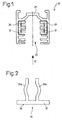
- the known 3-phase busbar 28 consists of a, in particular made of aluminum, substantially U-shaped profile 29, which has an insertion slot 30 for the head region 72 of a busbar adapter 39 (FIG. 5).
- a busbar 28 and the mechanical and electrical connection with a busbar adapter 39 or with a lamp 10 is hereby on the German patent application DE 103 12 012 A1 the applicant, the content of which is hereby included in the content of the present patent application, also for the purpose of reference to individual features.
- the prior art bus bar 28 includes a neutral and 3-phase conductors.
- a conventional busbar adapter for example according to the DE 103 12 012 A1 , a user can choose to which of the 3-phase conductor the respective lamp is to be connected. In this way, three groups of lights can be fixed to a power rail and controlled in groups in a conventional manner.
- the conventional 3-phase busbar can be switched such that two of the four conductors, eg the conductors 33 and 34, are connected as a signal line can be transmitted via the control information to the light 10.
- the other two conductors 31 and 32 are still used as power supply lines for the luminaire and are respectively switched as a phase conductor and as a neutral. While the power supply lines 31 and 32, thus corresponding to the power supply lines 19a and 19b of FIG. 3, transmit a high operating voltage of, for example, 230V, only the conductors 33 and 34 corresponding to the signal lines 20a and 20b of FIG Control information of a lower voltage, for example 25 V transmitted.
- the circuit according to the invention of the known busbar provides, on the one hand, that the signal lines 33 and 34 of the busbar 28 are connected to a control, not shown, of a network of the luminaires, the control, not shown, coupling the control information to the signal lines 33 and 34. If a bidirectional transmission of control information is provided, the information may also be decoupled from the signal line 33, 34.
- the circuit according to the invention of the known busbar 28 further provides that the lamp 10 to be connected to the busbar 28 and / or an operating device 15 assigned to the luminaire for the luminaire and / or a busbar adapter 39 for connecting the luminaire 10 to the busbar 28 a second terminal 18 or corresponding connection points 24a, 24b provides that can be connected to the conductors 33, 34 of the bus bar 28, being transmitted via this terminal 18 or via these connection points 24a, 24b control information.
- Fig. 2 shows only schematically indicated a marking element 35 in the manner of a clip, which has a cover plate 37 and two spring legs 36a and 36b.
- the Marking element 35 is inserted in the insertion direction of the arrow E in the receptacle 30 of the bus bar 28 and clipped there, with the insertion of the marking element 35, the two free ends of the spring legs 36a, 36b to move toward each other and slightly after reaching a preferably locked by latching means detent position can expand, so that a secure hold of the marking element 35 is achieved in the busbar 28.
- the cover plate 37 is provided on its underside with a signal surface 38 which may be labeled and may include, for example, a marker indicating that the bus bar 28 is switched to a particular state.
- the marker 35 indicates that the conventional bus bar 28 is in a state where the conductors 33 and 34 are shaded as signal lines due to the circuit of the present invention.
- the user is shown the peeling state of the bus bar 28 in a simple manner, whereby a very simple display option is provided by the clipable design of the marking element 35.
- a user can in this way be informed, by the marking element 35, whether he has received e.g. or not equipped with a DALI ballast can use this luminaire in this busbar.
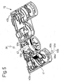
- Fig. 5 shows the busbar adapter according to the invention, which is designated in its entirety by 39, in a perspective view.
- the two housing halves 40a and 40b are unfolded.
- the housing corresponds in terms of its basic structure substantially to the housing of the busbar adapter according to the DE 103 12 012 A1 , the contents of which are hereby included in the content of the present application in order to avoid repetition and for the purpose of reference to individual features.
- the busbar adapter As in the known busbar adapter are in one of the two housing halves, namely in the left with respect to FIG. 5 housing half 40a, two switching shafts 41 and 42 about their respective longitudinal axis, which is indicated in Fig. 6 and designated there with 43 and 44 respectively , rotatably arranged.
- the first shift shaft 41 can be actuated by a manual attack on an operating lever 70
- the second shift shaft 42 can be actuated by attack on a widened, provided with a knurled edge 71 in a simple manner.
- the two housing halves 40a and 40b are pivoted about a film-hinge-like axis against each other and clipped together.
- the flat portion of the busbar adapter 39 designated in FIG. 5 by 72, is inserted into the insertion opening 30 of the busbar 28 according to FIG. 1 for mounting on the busbar 28.
- the first shift shaft 41 can be rotated by 90 °, wherein later to be described contact tongues 73a and 73b, retaining tongues 65a, 65b and an optionally provided Kodierzunge 66 from slots in the half-casings 40a, 40b emerge and into the corresponding grooves in the Busbar can occur.
- the second switching shaft 42 can be pivoted by 90 °, with corresponding contact tongues 73c and 73d emerge from corresponding slots or openings in the housing and the conductors 33, 34 can contact.
- the two switching shafts 41, 42 may, as is also the case with the known busbar adapter, be locked together via a locking arrangement, so that the second switching shaft 42 can only be turned into its contacting state when the first switching shaft 41 is in a contacting state. Under certain circumstances, such an arrangement may also be dispensed with in the busbar adapter according to the invention.
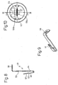
- Fig. 7 indicates in an exploded view that the second Schalfinrelle 42 two contact elements 48 a and 48 b are assigned, which are inserted in the insertion direction x in the hollow switching shaft 42.
- the selector shaft 42 is shown in a longitudinal section in FIG. 11 and comprises a head section 51, an axial section 50 and a foot section 52, which is significantly widened in relation to the head section 51.
- the switching shaft 42 is hollow overall, and includes two chambers 54 a and 54 b, which are separated by a partition 53 from each other.
- the partition wall 53 and the switching shaft 42 are made of an electrically insulating material, preferably made of plastic, and are manufactured as an injection molded part.
- the foot portion 52 has a plate 55 which is provided with two apertures 56a and 56b, so that the switching shaft 42 is provided over its entire axial length with a through opening.
- a to be introduced into the second switching shaft 42 contact element 48 is shown in Fig. 8 in cross section. It comprises a section 58 for forming the contact tongue, which contacts the corresponding conductor rail (eg conductor 33 according to FIG. 1) in the bus bar 28, and that from a central section 59 substantially at right angles is bent.
- An end portion 60 of the contact element is bent over and comprises at its free end a plug-in element 61 in the form of a tongue.
- the plug 61 is slightly offset parallel to the end portion 60.
- a nose 64 are located on the side facing away from the plug 61 side of the central portion 59th
- the two contact elements 48 a, 48 b are electrically separated from each other by the partition 53.
- the connecting conductors for the two contact elements 48a, 48b which are not shown in FIG. 11 and lead to the second terminal 18 of the operating device 15 or the luminaire 10, each have a blade receptacle at its end, which can be connected to the plug 61.
- An assembly of the blade receptacle on the tongue 61 can also be done before the contact element 48 is inserted into the second switching shaft 42. In this case, the contact element 48 and the blade receptacle with the end of the connecting conductor is fastened together on the switching shaft 42.
- the tongue 61 is slightly spaced from the partition wall 53 due to the bend 62, so that there is sufficient space for the flat receptacle, not shown. In principle, this also allows the mounting of the connection conductor with the blade receptacle on the contact element 48 or 48a or 48b, if the contact element is already fixed to the switching shaft 42.
- the tongue 61 extends both substantially along the pivot axis 44 of the second switching shaft 42, and is directed toward the base of the profile 29 of the conductor rail 28 in the assembled state of the contact element 48. A contacting of the tongue 61 through the connecting conductor thus takes place with respect to FIG. 8 from above. This allows, as shown in FIG. 5 only hinted, a supply of the two associated connecting conductors 69c and 69d from above into the switching shaft 42. This leads to a very space-saving overall design of the busbar adapter 39, which is not externally at all from the busbars Adapter of the prior art must be different.
- a cover member 63 is provided which closes the foot portion 52 of the second switching shaft 42 and thus completely covers the contact elements 48a and 48b.
- Fig. 6 shows that the contact elements 45a and 45b are formed substantially at right angles and have at their lower free end in each case a plug-in element 47a and 47b in the manner of a tongue.
- the tongue is used for connection to a mating plug element arranged at one end of a connection conductor 69a, 69b in the manner of a flat plug-in sleeve.
- a contact tongue 73a, 73b which in turn serves for connection to the conductor rails (eg conductors 32 and 31 according to FIG. 1) of the bus bar 28.
- the contact element 45a or 45b corresponds to virtually identical to that in Figures 9 to 12 in the DE 103 12 012 A1 described contact element.
- the attachment of such a contact element 45a and 45b is described in this patent application, so that reference is made to avoid repetition.
- FIG. 5 A special feature of the arrangement is shown in FIG. 5, from which it can be seen that the two connecting conductors 69c and 69d for the second switching shaft 42 are passed through the first switching shaft 41.
- an earth conductor not shown in FIG. 5 can be passed as a further connection conductor through the switching shaft, as shown for example in FIG DE 103 12 012 A1 is shown.
- the first switching shaft 41 is now provided with a first passageway 68a and a second passageway 68b for at least two connection conductors 69c and 69d.
- the connection conductors 69a and 69b associated with the contact elements 45a and 45b leave the foot portion 52 of the first switching shaft 41 together with the connection conductors 69c and 69d, so that the busbar adapter 39 has a common outlet 74 for all four connection conductors, or taking into account a ground conductor, a common outlet for five connection conductors. This common outlet facilitates the connection of the connecting cables with the lamp to be connected to the busbar adapter.
- a partition 46 can be arranged in the interior of the hollow, first control shaft 41. Under certain circumstances, however, these can also be dispensed with if the connecting conductors 69c and 69d are sufficiently insulated and have double insulation, for example.
- the first shift shaft 41 differs from the second shift shaft 42 still by retaining tongues 65a, 65b and a Kodierzunge 66.
- the first shift shaft 41 has a structure which basically in Fig. 8 of DE 103 12 012 A1 shown construction of a switching shaft identical. An additional Kodierzunge 66 is provided, but will not be further discussed in terms of their function at this point.
- contact elements 45a and 45b are inserted into corresponding chambers 67a and 67b in the first shift shaft 41 and can be secured axially by means of corresponding locking lugs 75 (FIG. 6), which engage behind corresponding wall regions 76 of the first shift shaft 41.
- the busbar adapter 39 has on the first switching shaft 41 two contact elements 45a and 45b, which can be brought into contact with the neutral conductor 31 of the busbar 28 and the phase conductor 32 of the busbar.
- the second switching shaft 42 has two contact elements 48 a and 48 b, which can be brought into contact with the signal lines 33, 34 of the bus bar 28. In this way, a lamp 10 can be connected as shown in FIG. 3 with a single busbar adapter 39 to the bus bar 28.
- the contact tongue 73a thus corresponds, for example, to a neutral contact tongue
- the contact tongue 73b corresponds to a phase conductor contact tongue
- the contact tongues 73c and 73d correspond to the signal line contact tongues.
Landscapes
- Circuit Arrangement For Electric Light Sources In General (AREA)
- Details Of Connecting Devices For Male And Female Coupling (AREA)
Abstract
Description
Die Erfindung betrifft zunächst eine Leuchte gemäß dem Oberbegriff des Anspruches 1.The invention initially relates to a luminaire according to the preamble of claim 1.
Derartige Leuchten sind bekannt und weit verbreitet. Sie werden auch von der Anmelderin seit Jahrzehnten hergestellt. Beispielhaft wird auf eine im aktuellen Katalog der Anmelderin Ausgabe 2004/2005 auf Seite 486 ff. beschriebene Focalflood-Leuchte hingewiesen, die mehrere unterschiedlich farbige Leuchtmittel aufweist. Die Leuchtmittel sind mit Spannungsversorgungsleitungen verbunden, die die Versorgungs- oder Betriebsspannung für die Leuchtmittel bereitstellen. Außerdem weist die Leuchte drei elektronische Vorschaltgeräte auf, so dass die drei Leuchtmittel einzeln ansteuerbar sind. Das Vorschaltgerät kann beispielsweise ein nach dem DALI-Protokoll arbeitendes Vorschaltgerät sein, welches einzeln adressierbar und mit einer Signalleitung verbunden ist. Die Leuchte kann in ein Netzwerk von Leuchten eingebunden sein und über eine zentrale Steuerung Steuerinformationen über die Signalleitung erhalten. Beispielsweise kann von der zentralen Steuerung an eines der Leuchtmittel der Leuchte die Information übermittelt werden, in einen bestimmten Dimmzustand zu treten, z.B. auch zum Zwecke der Farbmischung, zu blinken, sich einzuschalten, sich auszuschalten od. dgl.Such lights are known and widely used. They have also been manufactured by the Applicant for decades. By way of example, reference is made to a Focalflood luminaire described in the current catalog of Applicant Edition 2004/2005 on page 486 ff., Which has a plurality of differently colored illuminants. The bulbs are connected to power supply lines that provide the supply or operating voltage for the bulbs. In addition, the lamp has three electronic ballasts, so that the three bulbs are individually controlled. The ballast may for example be a working according to the DALI protocol ballast, which is individually addressable and connected to a signal line. The luminaire can be integrated into a network of luminaires and receive control information via the signal line via a central control. For example, the information may be transmitted from the central controller to one of the lamps of the luminaire to enter a certain dimming state, e.g. also for the purpose of color mixing, to flash, to turn on, to turn off or the like.
Die Spannungsversorgungsleitung, zu der üblicherweise ein Phasenleiter und ein Nullleiter gehört, wird typischerweise über einen ersten Anschluss mit der Leuchte verbunden und überträgt z.B. eine Betriebsspannung AC von 230 V bzw. 110 V. Zum Anschluss der Signalleitung ist an der Leuchte bzw. an dem der Leuchte zugeordneten Betriebsgerät, also z.B. dem elektronischen Vorschaltgerät, ein zweiter Anschluss vorgesehen. Die Signalleitung ist typischerweise eine zweiadrige Leitung, über die Spannungen bis beispielsweise 25 V übertragen werden. Die Signalleitung wird im Normalfalle gesondert von den Spannungsversorgungsleitungen verlegt.The power supply line, which usually includes a phase conductor and a neutral conductor, is typically connected to the luminaire via a first connection and transmits, for example, an operating voltage AC of 230 V or 110 V. For connecting the signal line to the luminaire or to the Luminaire associated operating device, so for example the electronic ballast, a second connection provided. The signal line is typically one two-core cable, via which voltages up to 25 V, for example, are transmitted. The signal line is normally laid separately from the power supply lines.
Ausgehend von einer Leuchte gemäß dem Oberbegriff des Anspruches 1 besteht die Aufgabe der Erfindung darin, eine Leuchte bereitzustellen, die eine größere Sicherheit gegenüber Montagefehlern bietet.Starting from a lamp according to the preamble of claim 1, the object of the invention is to provide a lamp that offers greater security against assembly errors.
Die Erfindung löst diese Aufgabe mit den Merkmalen des Anspruches 1, insbesondere mit denen des Kennzeichenteils, und ist demgemäß dadurch gekennzeichnet, dass dem zweiten Anschluss eine Sicherung gegen Überspannung zugeordnet ist, die austauschbar oder schaltbar ausgebildet ist.The invention solves this problem with the features of claim 1, in particular with those of the characterizing part, and is accordingly characterized in that the second connection is associated with a fuse against overvoltage, which is formed exchangeable or switchable.
Das Prinzip der Erfindung besteht somit im Wesentlichen darin, eine Sicherung vorzusehen, die bei Überschreiten einer Soll-Spannung ausgelöst werden kann. Kommt es zu einer Fehlmontage, das heißt zu einem Fehlanschluss der Leitungen, so dass an dem zweiten Anschluss für die Signalleitung versehentlich die deutlich höhere Betriebsspannung anliegt, kann die Sicherung ausgelöst werden. Ist die Sicherung vorteilhaft als Schmelzsicherung ausgebildet, kann der Schmelzfaden infolge einer Erhitzung durchschmelzen und so die in Stromrichtung hinter der Sicherung angeordnete Leuchte oder das Betriebsgerät der Leuchte sowie die dort befindliche Elektronik vor Überspannung durch Unterbrechung des Stromkreises schützen. Würde ansonsten die hohe Betriebsspannung von beispielsweise 230 V auf einen z.B. 12 V-Niedervolt-Transformator treffen, könnte sich z.B. Kupferdampf entwickeln, der neben unmittelbaren gesundheitlichen Schädigungen der Monteure in nachteiliger Weise auch eine Beeinträchtigung der elektrischen und elektronischen Teile der Leuchte herbeiführen kann, wenn isolierende Teile oder Flächen durch einen Niederschlag des Kupferdampfes leitend ausgebildet werden, was weitere Folgeschäden hervorrufen kann. Auch andere Beschädigungen von Teilen der Leuchte oder des Betriebsgerätes sind möglich.The principle of the invention thus consists essentially in providing a fuse which can be triggered when a nominal voltage is exceeded. If there is a faulty mounting, that is to say a faulty connection of the lines, so that the significantly higher operating voltage is inadvertently applied to the second connection for the signal line, the fuse can be tripped. If the fuse is advantageously designed as a fuse, the melted thread can melt as a result of heating and thus protect the downstream of the fuse arranged light or the operating device of the lamp and the electronics located there against overvoltage by interrupting the circuit. Otherwise, if the high operating voltage of 230 V, for example, would affect a 12 V low-voltage transformer, for example, copper vapor could develop, which, in addition to direct health damage to the fitters, could also adversely affect the electrical and electronic parts of the luminaire if insulating parts or surfaces are made conductive by a precipitate of the copper vapor, which can cause further consequential damage. Other damage to parts of the lamp or the control gear are possible.
Die Sicherung ist im Falle einer zerstörerischen Auslösung, wie beispielsweise bei einer Schmelzsicherung, austauschbar ausgebildet. Hierzu ist eine Schmelzsicherung vorteilhafterweise an einem leicht zugänglichen Ort der Leuchte angeordnet und kann, beispielsweise durch herkömmliche Federklemmen gehaltert sein und nach Auslösung durch eine neue Sicherung ausgetauscht werden. Alternativ kann die Sicherung aber auch schaltbar ausgebildet sein, so dass sie selbsttätig, bei Detektion einer eine Soll-Spannung überschreitenden Überspannung, auslöst und nachfolgend entweder manuell aus ihrem ausgelösten, die Stromleitung unterbrechenden Zustand in einen Strom leitenden Zustand zurückgeschaltet werden kann oder automatisch rückschaltet, beispielsweise nach Ablauf einer bestimmten Zeitdauer.The fuse is interchangeable in the event of destructive tripping, such as a fuse. For this purpose, a fuse is advantageously arranged at an easily accessible location of the lamp and can be supported, for example, by conventional spring clips and replaced after release by a new fuse. Alternatively, however, the fuse may also be designed to be switchable, so that it triggers automatically upon detection of a nominal voltage exceeding overvoltage, and subsequently either manually switched from its tripped, the power line interrupting state in a current-conducting state or automatically switches back, for example, after a certain period of time.
Von entscheidender Bedeutung ist, dass die Sicherung sehr schnell auslöst und im ausgelösten Zustand auch hohe Spannungen von bis in die Größenordnung von 400 V sicher und dauerhaft trennt. Diese hohe Durchschlagfestigkeit der ausgelösten Sicherung ist erforderlich, für den Fall, dass anstelle zweier Signalleitungen zwei Phasenleiter unterschiedlichen Potentials mit dem zweiten Anschluss verbunden werden.Of crucial importance is that the fuse triggers very quickly and safely and permanently disconnects even high voltages of up to 400 V in the tripped state. This high breakdown strength of the tripped fuse is required in the event that instead of two signal lines, two phase conductors of different potential are connected to the second terminal.
Besonders vorteilhaft ist die Sicherung dann, wenn die Leuchte an eine Stromschiene angeschlossen werden soll. Die Sicherung kann in dem Falle einer fehlerhaften Montage und einer Fehlbelegung der Leiter in der Stromschiene sicher auslösen und die Leuchte bzw. das Betriebsgerät der Leuchte schützen.Particularly advantageous is the fuse when the lamp is to be connected to a power rail. The fuse can safely trip in the event of faulty mounting and a faulty assignment of the conductor in the busbar and protect the lamp or the operating device of the lamp.
Die Anordnung der austauschbaren Sicherung oder einer manuell rückschaltbaren Sicherung an einem leicht zugänglichen Ort kann beispielsweise bedeuten, dass lediglich ein Gehäuseteil der Leuchte oder eines Betriebsgerätes der Leuchte entfernt werden muss, wobei nach Entfernung des Gehäuseteiles z.B. eine Halterungseinrichtung für die Schmelzsicherung zugänglich ist, so dass die Sicherung entnommen und durch eine neue Sicherung ersetzt werden kann.The arrangement of the replaceable fuse or a manually switchable fuse in an easily accessible place, for example, mean that only a housing part of the lamp or an operating device of the lamp must be removed, wherein After removal of the housing part, for example, a mounting device for the fuse is accessible, so that the fuse can be removed and replaced by a new fuse.
Gemäß einer vorteilhaften Ausgestaltung der Erfindung ist der Leuchte ein Betriebsgerät zugeordnet, an dem der erste und/oder der zweite Anschluss angeordnet ist. Als Betriebsgerät der Leuchte wird beispielsweise ein elektronisches Vorschaltgerät, ein Transformator oder ein anderes, der Leuchte unmittelbar zugeordnetes Gerät bezeichnet, mit dem die Funktion der Leuchte steuerbar ist. Das Betriebsgerät ist typischerweise unmittelbar nahe an der Leuchte angeordnet und kann sich beispielsweise in dem Gehäuse der Leuchte oder in einem gesonderten Betriebsgerätgehäuse befinden. Für den Fall, dass die Leuchte über einen Stromschienen-Adapter mit der Stromschiene verbunden ist, kann sich das Betriebsgerät auch innerhalb eines Gehäuses des Stromschienen-Adapters befinden.According to an advantageous embodiment of the invention, the lamp is associated with a control gear on which the first and / or the second terminal is arranged. As the operating device of the lamp, for example, an electronic ballast, a transformer or another, the lamp directly associated device is referred to, with which the function of the lamp is controlled. The operating device is typically arranged directly next to the luminaire and may be located, for example, in the housing of the luminaire or in a separate operating device housing. In the event that the lamp is connected via a busbar adapter to the busbar, the operating device may also be located within a housing of the busbar adapter.
Gemäß einer vorteilhaften Ausgestaltung der Erfindung sind dem zweiten Anschluss zwei Eingänge für Signalleitungen zugeordnet, die über ein elektronisches Bauelement, insbesondere über einen Varistor, derart miteinander kurzgeschlossen sind, dass bei Überschreiten einer Soll-Spannung zwischen den beiden Eingängen ein großer Stromfluss durch die Sicherung verursacht wird. Dieser Stromfluss kann die Sicherung auslösen.According to an advantageous embodiment of the invention, two inputs for signal lines are assigned to the second terminal, which are short-circuited with each other via an electronic component, in particular via a varistor, that causes a large current flow through the fuse when a desired voltage between the two inputs is exceeded becomes. This current flow can trigger the fuse.
Während bei geringeren Spannungen, also im Falle eines ordnungsgemäßen Anschlusses, das elektronische Bauelement praktisch nicht in Erscheinung tritt, beispielsweise weil sein elektrischer Widerstand sehr hoch ist, so dass durch das elektronische Bauelement im Normalfall überhaupt kein Strom hindurchfließt, kann bei Überschreiten einer Soll-Spannung, nämlich im Falle einer Fehlmontage, durch das elektronische Bauelement hindurch ein Strom fließen, weil sich infolge der großen Spannung, z.B. oberhalb einer Schwellspannung von 60 V, der elektrische Widerstand durch das Bauelement hindurch verringert. Ein solches an sich bekanntes Bauelement ist beispielsweise ein Varistor (variable Resistor).While at lower voltages, so in the case of a proper connection, the electronic component practically does not appear, for example, because its electrical resistance is very high, so that flows through the electronic component normally no current, can exceed a target voltage , namely, in the case of a faulty mounting, through the electronic component through a current flow, because due to the large voltage, for example, above a threshold voltage of 60 V, the electrical resistance through the Component through reduced. Such a per se known device is for example a varistor (variable resistor).
Wird im Falle einer Fehlmontage versehentlich statt der Signalleitung ein Paar von Phasenleitern mit dem zweiten Anschluss verbunden, so wird infolge des großen Stromflusses durch das elektronische Bauelement auch ein entsprechender Stromfluss durch die Sicherung hindurch verursacht. Im Falle einer Schmelzsicherung führt dieser große Stromfluss infolge der Ohm'schen Wärme zu einem Schmelzen des Schmelzleiters und zu einem Auslösen der Sicherung. Sobald die Sicherung ausgelöst ist und der Stromkreis unterbrochen ist, ist die in Stromrichtung hinter der Sicherung angeordnete Elektronik des Betriebsgerätes und der Leuchte vor der Überspannung geschützt, so dass keine Schäden an diesen Bauteilen hervorgerufen werden. Nach Auslösen der Sicherung muss lediglich die Sicherung ausgetauscht oder zurückgeschaltet werden, nicht jedoch das wesentlich hochwertigere Betriebsgerät oder die wesentlich hochwertigere Leuchte.If a pair of phase conductors are inadvertently connected to the second terminal instead of the signal line in the event of a faulty mounting, a corresponding current flow through the fuse is also caused as a result of the large current flow through the electronic component. In the case of a fuse, this large current flow due to the ohmic heat leads to melting of the fusible conductor and to a triggering of the fuse. As soon as the fuse has tripped and the circuit is interrupted, the electronics of the operating device and the luminaire arranged in the current direction behind the fuse are protected against overvoltage, so that no damage is caused to these components. After triggering the fuse only the fuse must be replaced or switched back, but not the much higher quality equipment or the much higher quality lamp.
Gemäß einer vorteilhaften Ausgestaltung der Erfindung wird die Sicherung erst oberhalb einer Spannung von 30 V oder 50 V, insbesondere oberhalb von 230 V, weiter insbesondere oberhalb von 300 V ausgelöst. Diese Ausgestaltung der Erfindung berücksichtigt zunächst, dass die über die Signalleitung übertragenen Steuerinformationen als Signale typischerweise nur geringere Spannungen von weniger als 30 V, in jedem Falle aber von weniger als 230 V aufweisen. Für den Fall, dass anstelle zweier Signalleitungen an den zweiten Anschluss versehentlich zwei Phasen leiter angeschlossen sind, können Spannungsamplituden von mehr als 400 V auftreten, so dass die Sicherung und der Varistor entsprechend ausgelegt werden müssen. Die Spannung, oberhalb der die Sicherung ausgelöst wird, soll erfindungsgemäß so gewählt werden, dass sie oberhalb der zur Übertragung der Steuerinformationen verwendeten Spannung zuzüglich einem gewissen Aufschlag zum Ausgleich von Toleranzen, beispielsweise in der Größenordnung einiger Volt oder einiger 10 Volt, liegt.According to an advantageous embodiment of the invention, the fuse is triggered only above a voltage of 30 V or 50 V, in particular above 230 V, further in particular above 300V. This embodiment of the invention initially takes into account that the control information transmitted via the signal line as signals typically have only lower voltages of less than 30 V, but in any case of less than 230 V. In the event that instead of two signal lines to the second terminal by mistake two phase conductors are connected, voltage amplitudes of more than 400 V may occur, so that the fuse and the varistor must be designed accordingly. The voltage above which the fuse is triggered should, according to the invention, be selected such that it exceeds the voltage used to transmit the control information plus a certain surcharge to compensate for tolerances, for example, on the order of a few volts or a few tens of volts.
Gemäß einer weiteren vorteilhaften Ausgestaltung der Erfindung entsprechen die Steuerinformationen dem DALI-Protokoll (Digital Addressable Lighting Interface). Dieses von der Arbeitsgemeinschaft DALI beim Zentralverband der deutschen Elektrotechnik- und Elektronikindustrie e.V. (ZVEI) erarbeitete Protokoll ist beispielsweise in allen Einzelheiten in dem vorveröffentlichten
Die Erfindung betrifft des Weiteren ein Betriebsgerät für eine Leuchte, insbesondere ein elektronisches Vorschaltgerät, gemäß dem Oberbegriff des Anspruches 6.The invention further relates to an operating device for a luminaire, in particular an electronic ballast, according to the preamble of claim 6.
Ein derartiges Betriebsgerät kann Bestandteil einer Leuchte sein oder gesondert von der Leuchte, vorzugsweise unmittelbar der Leuchte benachbart, angeordnet sein. Neben elektronischen Vorschaltgeräten kommen auch andere Geräte für eine Leuchte als Betriebsgerät in Betracht, mit denen die Leuchte gedimmt, ein- oder ausgeschaltet werden können oder mit denen in sonstiger Weise das Abstrahlverhalten oder die Farbe der Leuchte beeinflusst werden oder ein Leuchtmittel der Leuchte angesprochen werden kann.Such an operating device may be part of a lamp or separately from the lamp, preferably immediately adjacent to the lamp, arranged. In addition to electronic ballasts are also other devices for a lamp as operating equipment into consideration, with which the lamp can be dimmed, switched on or off or with which the radiation behavior or the color of the lamp can be influenced in any other way or a light source of the lamp can be addressed ,
Ein Betriebsgerät des Standes der Technik weist typischerweise einen ersten Anschluss zur Verbindung mit einer Spannungsversorgungsleitung auf, mit der die Versorgungsspannung zum Betrieb eines Leuchtmittels der Leuchte übertragen wird. Das Betriebsgerät weist des Weiteren einen zweiten Anschluss für eine Signalleitung auf, mit der Steuerinformationen zur Steuerung der Leuchte übertragen werden. Die Steuerinformationen können beispielsweise gemäß dem DALI-Protokoll ausgebildet sein.A control gear of the prior art typically has a first terminal for connection to a power supply line, with which the supply voltage for the operation of a light source of the lamp is transmitted. The operating device furthermore has a second connection for a signal line, with which control information for controlling the luminaire is transmitted. The control information may be formed, for example, according to the DALI protocol.
Ein Ausgang des Betriebsgerätes ist typischerweise mit dem Leuchtmittel verbunden, so dass in Abhängigkeit von den erhaltenen Steuerinformationen bzw. Steuerbefehlen das Betriebsgerät eine entsprechende Ansteuerung des Leuchtmittels oder der Leuchtmittel vornehmen kann.An output of the operating device is typically connected to the lighting means, so that depending on the control information or control commands received, the operating device can perform a corresponding control of the lighting means or of the lighting means.
Ausgehend von diesem Stand der Technik besteht die Aufgabe der Erfindung darin, das durch offenkundige Vorbenutzung bekannt gewordene Betriebsgerät des Oberbegriffes des Anspruches 6 derart weiterzubilden, dass eine größere Sicherheit gegenüber Montagefehlern erzielt wird.Based on this prior art, the object of the invention is to develop the well-known by public prior use operating device of the preamble of claim 6 such that a greater security against assembly errors is achieved.
Die Erfindung löst diese Aufgabe mit den Merkmalen des Anspruches 6, insbesondere mit denen des Kennzeichenteils, und ist demgemäß dadurch gekennzeichnet, dass dem zweiten Anschluss eine Sicherung gegen Überspannung zugeordnet ist, die austauschbar oder schaltbar ausgebildet ist.The invention solves this problem with the features of claim 6, in particular with those of the characterizing part, and is accordingly characterized in that the second terminal is associated with a fuse against overvoltage, which is formed exchangeable or switchable.
Zur Vermeidung von Wiederholungen wird auf die obigen Ausführungen zu den Ansprüchen 1 bis 5 verwiesen, wobei die Bezüge, Beschreibungen und Vorteile, die sich dort auf eine Leuchte beziehen, nunmehr in analoger Weise auf das Betriebsgerät für die Leuchte zutreffen.To avoid repetition, reference is made to the above statements to the claims 1 to 5, wherein the references, descriptions and advantages that relate there to a lamp, apply now in an analogous manner to the operating device for the lamp.
Die Sicherung entspricht der zuvor im Zusammenhang mit einer Leuchte beschriebenen Sicherung. Diese ist wiederum austauschbar oder schaltbar ausgebildet. Die Sicherung kann unmittelbar in das Betriebsgerät inkorporiert sein oder dem Betriebsgerät vorgeschaltet sein.The fuse corresponds to the fuse previously described in connection with a lamp. This is again designed exchangeable or switchable. The fuse can be incorporated directly into the operating device or upstream of the operating device.
Des Weiteren betrifft die Erfindung eine Stromschiene gemäß dem Oberbegriff des Anspruches 10.Furthermore, the invention relates to a busbar according to the preamble of
Eine derartige Stromschiene ist beispielsweise aus der
Die Leuchte verfügt über einen ersten Anschluss, über den sie mit dem Phasenleiter der Stromschiene verbindbar ist, sowie über wenigstens einen zweiten Anschluss, über den sie mit der Signalleitung der Stromschiene verbindbar ist. Den beiden Anschlüssen an der Leuchte entsprechen selbstverständlich Abgreifpunkte in den Leiterschienen der Stromschiene. Die Leuchte kann wiederum ein Betriebsgerät aufweisen, welches infolge eines Empfanges von Steuerinformationen das Leuchtmittel entsprechend ansteuern kann. Alternativ zu einer Anordnung des Betriebsgerätes in der Leuchte kann das Betriebsgerät mit den beiden Anschlüssen der Leuchte auch nur zugeordnet sein.The luminaire has a first connection, via which it can be connected to the phase conductor of the busbar, and via at least one second connection, by means of which it can be connected to the signal line of the busbar. Naturally, the two connections on the luminaire correspond to tapping points in the conductor rails of the busbar. The luminaire may in turn have an operating device which, as a result of receiving control information, can control the luminous means accordingly. As an alternative to an arrangement of the operating device in the luminaire, the operating device may also only be associated with the two terminals of the luminaire.
Ausgehend von der vorbekannten Stromschiene besteht die Aufgabe der Erfindung darin, eine Stromschiene gemäß dem Oberbegriff des Anspruches 10 derartig weiterzubilden, dass sie die Leuchte oder ein Betriebsgerät für die Leuchte gegen Folgen einer Fehlmontage oder eines Fehlanschlusses an die Stromschiene besser schützt.Based on the previously known busbar, the object of the invention is to further develop a busbar according to the preamble of
Die Erfindung löst diese Aufgabe mit den Merkmalen des Anspruches 10, insbesondere mit denen des Kennzeichenteiles, und ist demgemäß dadurch gekennzeichnet, dass dem zweiten Anschluss eine Sicherung gegen Überspannung zugeordnet ist, die austauschbar oder schaltbar ausgebildet ist.The invention solves this problem with the features of
Zur Vermeidung von Wiederholungen wird auf die obigen Ausführungen verwiesen, die die Würdigung der Ansprüche 1 bis 5 betreffen, wobei angemerkt sei, dass die Bezüge, die Beschreibungen und die Vorteile, soweit sie sich dort auf eine Leuchte beziehen, in analoger Weise auch Anwendung bei der erfindungsgemäßen Stromschiene finden, an die eine Leuchte oder ein Betriebsgerät angeschlossen wird.To avoid repetition, reference is made to the above statements, which relate to the appraisal of claims 1 to 5, it being noted that the covers, the descriptions and the advantages, as far as they relate to a luminaire, in an analogous manner with application find the busbar according to the invention, to which a lamp or a control gear is connected.
Wesentlicher Vorteil der erfindungsgemäßen Stromschiene ist, dass an eine herkömmliche Stromschiene, die beispielsweise drei Phasenleiter und einen Nullleiter aufweist, nunmehr auch eine Leuchte, die über eine Signalleitung Steuerinformationen erhält, anschließbar ist, ohne dass Montagefehler gravierende Konsequenzen hervorrufen. Die Anordnung einer Sicherung gegen Überspannung, die austauschbar oder schaltbar ausgebildet ist, ermöglicht dabei einen Schutz der hochwertigen Betriebsgeräte bzw. der Leuchte im Falle einer Überspannung infolge eines Montagefehlers. Durch Austausch der Sicherung bzw. durch Rückschaltung der Sicherung aus dem ausgelösten Zustand in einen Ruhezustand, in dem sie leitet, kann nach korrigierter Montage ohne großen Aufwand die Betriebsfähigkeit der Leuchte bzw. des Betriebsgerätes wieder hergestellt werden.An essential advantage of the busbar according to the invention is that a conventional busbar, which has, for example, three phase conductors and a neutral conductor, now also a luminaire, which receives control information via a signal line, can be connected without causing assembly errors serious consequences. The arrangement of a fuse against overvoltage, which is designed to be interchangeable or switchable, allows protection of the high-quality equipment or the lamp in the event of overvoltage due to a mounting error. By replacing the fuse or by switching back the fuse from the tripped state in a state of rest in which it passes, the operability of the lamp or the operating device can be restored after a great effort to correct installation.
Die Sicherung kann dabei beispielsweise auch an der Stromschiene angeordnet werden oder unmittelbar oder mittelbar fest an einem Adapter od. dgl. angeordnet sein, der an der Stromschiene befestigt wird.The fuse can be arranged, for example, on the busbar or od directly or indirectly fixed to an adapter. The like. Be arranged, which is attached to the power rail.
Die Erfindung betrifft des Weiteren eine Schaltungsanordnung gemäß dem Oberbegriff des Anspruches 14.The invention further relates to a circuit arrangement according to the preamble of claim 14.
Die Aufgabe dieser Erfindung besteht darin, eine Schaltungsanordnung für eine Leuchte oder für ein Betriebsgerät oder für eine Stromschiene unanfälliger hinsichtlich einer Fehlmontage auszugestalten.The object of this invention is a circuit arrangement for a lamp or for a control gear or to design for a busbar less prone to incorrect assembly.
Die Erfindung löst diese Aufgabe mit den Merkmalen des Anspruches 14, insbesondere mit denen des Kennzeichenteils, und ist demgemäß dadurch gekennzeichnet, dass dem zweiten Anschluss eine Sicherung gegen Überspannung zugeordnet ist, die austauschbar oder schaltbar ausgebildet ist.The invention solves this problem with the features of claim 14, in particular with those of the characterizing part, and is accordingly characterized in that the second connection is associated with a fuse against overvoltage, which is formed exchangeable or switchable.
Das Prinzip und die. Vorteile dieser Erfindung verstehen sich am besten im Hinblick auf das unter Bezug auf eine Leuchte geschilderte Prinzip der Erfindung und anhand der Würdigung der Ansprüche 1 bis 5, so dass zur Vermeidung von Wiederholungen auf die obigen Ausführungen verwiesen wird, die analog auch auf eine Schaltungsanordnung zutreffen.The principle and the. Advantages of this invention are best understood with regard to the principle of the invention described with reference to a luminaire and with reference to the appended claims 1 to 5, so that reference is made to avoid repetition of the above statements, which apply analogously to a circuit arrangement ,
Die erfindungsgemäße Schaltungsanordnung kann auch gesondert von einer Leuchte oder einem Betriebsgerät oder einer Stromschiene hergestellt werden und als gesondertes Bauelement an eine Leuchte oder an ein Betriebsgerät oder an eine Stromschiene angeschlossen werden.The circuit arrangement according to the invention can also be produced separately from a luminaire or an operating device or a busbar and connected as a separate component to a lamp or to a control gear or to a power rail.
Die Erfindung betrifft des Weiteren eine Stromschiene gemäß dem Oberbegriff des Anspruches 18.The invention further relates to a busbar according to the preamble of
Die bekannte Stromschiene wird beispielsweise unter der Bezeichnung 3-Phasen-Stromschiene seit Jahrzehnten von der Anmelderin gefertigt. Sie umfasst typischerweise drei Phasenleiter und einen Nulleiter, über die eine Leuchte oder mehrere Leuchten mit Betriebsspannung versorgt werden können. Hierzu wird typischerweise ein Stromschienen-Adapter in die nach Art eines U-Profiles ausgebildete Stromschiene eingesetzt und mit der Stromschiene mechanisch und elektrisch verriegelt. Die unterschiedlichen Phasenleiter können wahlweise kontaktiert werden, um die Leuchte z.B. an eine Gruppe von Leuchten anzuschließen, die als Leuchtengruppe ansteuerbar ist.The known busbar is manufactured, for example, under the name 3-phase busbar for decades by the applicant. It typically comprises three phase conductors and a neutral conductor, via which one or more lamps can be supplied with operating voltage. For this purpose, a busbar adapter is typically used in the formed in the manner of a U-profile busbar and mechanically and electrically locked to the busbar. The different phase conductors can optionally be contacted to the lamp, for example to connect to a group of luminaires, which can be controlled as lighting group.
Die Aufgabe der Erfindung besteht darin, die bekannte Stromschiene derart weiterzubilden, dass die Steuerung der Leuchten vereinfacht wird.The object of the invention is to develop the known busbar such that the control of the lights is simplified.
Die Erfindung löst diese Aufgabe mit den Merkmalen des Anspruches 18, insbesondere mit denen des Kennzeichenteils, und ist demgemäß dadurch gekennzeichnet, dass eine Schaltung vorgesehen ist, die einen der beiden . Leiter als Signalleitung zur Versorgung der Leuchte mit Steuerinformationen schaltet.The invention solves this problem with the features of
Das Prinzip der Erfindung besteht im Wesentlichen darin, eine herkömmliche Stromschiene, z.B. eine 3-Phasen-Stromschiene, durch eine Schaltung derartig anzuschließen, dass einer oder mehrere der vorhandenen Leiter, vorzugsweise zwei Leiter, in herkömmlicher Weise zur Spannungsversorgung der Leuchte verwendet werden, wobei wenigstens einer, vorteilhafterweise zwei, der vorhandenen Leiter, in neuartiger Weise als Signalleitung zur Versorgung der Leuchte mit Steuerinformationen verwendet werden.The principle of the invention consists essentially in a conventional busbar, e.g. a 3-phase busbar to be connected by a circuit such that one or more of the existing conductors, preferably two conductors, are used in a conventional manner to power the luminaire, wherein at least one, advantageously two, of the existing conductors, in a novel way Signal line to supply the lamp with control information can be used.
Durch Anordnung der Schaltung können auch vorhandene, in einem Gebäude fest installierte Stromschienen dazu verwendet werden, Leuchten, die z.B. ein DALI-Vorschaltgerät oder DALI-Betriebsgerät aufweisen, ansteuern zu können. Die DALI-Leuchten können ihre Steuerinformationen über die vorhandene Stromschiene erhalten, ohne dass zusätzliche Leitungen installiert werden müssen. Der Installationsaufwand ist somit sehr gering, erfordert er doch lediglich eine geänderte Beschaltung der Stromschiene. Vorhandene 3-Phasen-Stromschienen sind somit auf einfache Weise nachrüstbar.By arranging the circuit also existing, permanently installed in a building tracks can be used to control lights that have, for example, a DALI ballast or DALI control gear. The DALI luminaires can receive their control information via the existing busbar without having to install additional cables. The installation effort is thus very low, it only requires a modified wiring of the busbar. Existing 3-phase busbars are thus easily retrofitted.
Die neu vorgesehene Schaltung kann vorzugsweise einen Schaltungsteil umfassen, der ein Ende der Stromschiene mit einer zentralen Steuerung für ein Netzwerk von Leuchten verbindet.The newly provided circuit may preferably comprise a circuit part connecting one end of the bus bar to a central controller for a network of lights.
Die Erfindung ermöglicht den Rückgriff auf vorhandene Stromschienensysteme, die lediglich auf eine andere als die herkömmliche Weise angeschlossen werden müssen, wobei die Stromschiene nicht mit drei Phasenleitern und einem Nullleiter, sondern mit einem Nullleiter einem Phasenleiter und mit einer Steuerungseinheit des DALI-Netzwerkes oder eines anderen Netzwerkes verbunden ist.The invention makes it possible to use existing busbar systems, which need only be connected in a different way than the conventional one, the busbar not having three phase conductors and a neutral, but a neutral conductor, a phase conductor and a control unit of the DALI network or another Network is connected.
Gemäß einer vorteilhaften Ausgestaltung der Erfindung ist an der Stromschiene ein Markierungselement angeordnet, welches anzeigt, dass einer der Leiter zur Übertragung von Steuerinformationen verwendet wird.According to an advantageous embodiment of the invention, a marking element is arranged on the busbar, which indicates that one of the conductors is used for the transmission of control information.
Dies ermöglicht eine besonders einfache Anzeige, in welchem Modus sich die Stromschiene befindet, bzw. wie die Stromschiene gerade geschaltet ist. Die Person, die an der Stromschiene eine Leuchte befestigen möchte, kann auf diese Weise schnell und sicher feststellen, ob die Stromschiene als herkömmliche 3-Phasen-Stromschiene geschaltet ist oder in erfindungsgemäßer Weise nach Art einer 1-Phasen-Stromschiene, die zwei Steuerleitungen aufweist, geschaltet ist.This allows a particularly simple indication of the mode in which the busbar is located or how the busbar is currently connected. The person who wants to attach a lamp to the busbar, can quickly and safely determine in this way, whether the busbar is connected as a conventional 3-phase busbar or in accordance with the invention in the manner of a 1-phase busbar having two control lines , is switched.
Das Markierungselement kann weiter vorteilhafterweise lösbar an der Stromschiene befestigbar sein, so dass es als Zusatzelement oder Zubehörteil Verwendung finden kann. Weiter vorteilhaft ist das Markierungselement an die Stromschiene anclipsbar, so dass ohne besondere Hilfsmittel eine Montage des Markierungselementes an der Stromschiene vorgenommen werden kann.The marking element can further advantageously be detachably fastened to the busbar, so that it can be used as an additional element or accessory. Further advantageously, the marking element is clipped to the busbar, so that without special aids a mounting of the marking element can be made on the busbar.
Die Erfindung betrifft schließlich einen Stromschienen-Adapter gemäß dem Oberbegriff des Anspruches 25.Finally, the invention relates to a busbar adapter according to the preamble of
Ein solcher Stromschienen-Adapter ist beispielsweise aus der
Der bekannte Stromschienen-Adapter dient der mechanischen und elektrischen Verbindung einer Leuchte mit einer Stromschiene. Gleichermaßen kann der Adapter, falls ein Betriebsgerät vorhanden ist, auch der mechanischen und elektrischen Verbindung des Betriebsgerätes, sowie gegebenenfalls zugleich auch der Leuchte, mit der Stromschiene dienen. In das Gehäuse des Stromschienen-Adapters kann dazu beispielsweise auch das Betriebsgerät mit inkorporiert sein.The known busbar adapter serves for the mechanical and electrical connection of a lamp with a busbar. Similarly, the adapter, if an operating device is present, and the mechanical and electrical connection of the operating device, and possibly also at the same time also serve the light with the busbar. In the housing of the busbar adapter can also be incorporated, for example, the operating device with.
Der bekannte Stromschienen-Adapter der Anmelderin kommt in vorteilhafter Weise bereits mit einer sehr geringen Anzahl von Bauteilen aus und ermöglicht eine besonders einfache Montage. Der bekannte Stromschienen-Adapter weist dazu eine erste und eine zweite Schaltwelle auf, die einerseits über eine Phasenleiter-Kontaktzunge und andererseits über eine Nullleiter-Kontaktzunge verfügen, mit denen die Leiterschienen in der Stromschiene kontaktierbar sind.The known busbar adapter of the applicant comes in an advantageous manner already with a very small number of components and allows a particularly simple installation. The known busbar adapter has for this purpose a first and a second switching shaft, on the one hand via a phase conductor contact tongue and on the other hand have a neutral contact tongue, with which the conductor rails in the busbar are contacted.
Ausgehend von diesem Stand der Technik besteht die Aufgabe dieser Erfindung darin, einen Stromschienen-Adapter gemäß dem Oberbegriff des Anspruches 1 derart weiterzubilden, dass bei einfacher Bauweise auch eine Leuchte, die einen ersten Anschluss zur Verbindung mit einer Spannungsversorgungsleitung und einen zweiten Anschluss zur Verbindung mit einer Signalleitung aufweist, mit der Stromschiene verbindbar ist.Based on this prior art, the object of this invention is to develop a busbar adapter according to the preamble of claim 1 such that in a simple design, a light having a first terminal for connection to a power supply line and a second terminal for connection a signal line, with the busbar is connectable.
Die Erfindung löst diese Aufgabe mit den Merkmalen des Anspruches 25, insbesondere mit denen des Kennzeichenteils, und ist demgemäß dadurch gekennzeichnet, dass jede Schaltwelle jeweils zwei mit der Schaltwelle drehverbundene Kontaktelemente aufweist.The invention solves this problem with the features of
Das Prinzip der Erfindung besteht im Wesentlichen darin, beiden Schaltwellen jeweils zwei Kontaktelemente zuzuordnen. Sämtliche Kontaktelemente können durch geschickte Anordnung trotz der sehr beengten Platzverhältnisse in den Schaltwellen untergebracht werden. Jedes Kontaktelement weist ein Steckelement, vorzugsweise eine Steckzunge auf. Das Steckelement, kann mit einem Anschlussleiter, der ein Gegensteckelement aufweist, verbunden werden. Das Gegensteckelement kann beispielsweise eine Flachsteck-Hülse sein.The principle of the invention consists essentially in assigning two switching elements each two contact elements. All contact elements can be accommodated by skillful arrangement despite the very tight space in the switching shafts. Each contact element has a plug-in element, preferably a tongue. The plug element can be connected to a connection conductor which has a mating plug element. The mating plug element may for example be a flat plug sleeve.
Das Steckelement, vorzugsweise jedes Steckelement, ist in der Nähe der Schwenkachse der Schaltwelle angeordnet. Außerdem ist das Steckelement, vorzugsweise jedes Steckelement, im Wesentlichen entlang der Schwenkachse der zugehörigen Schaltwelle ausgerichtet, das heißt parallel zur Schwenkachse. Durch diese Anordnung kann die Biegebeanspruchung der Anschlussleiter infolge einer Schwenk- oder Drehbewegung der Schaltwelle sehr gering gehalten werden. Eine Beschädigung der Anschlussleiter wird damit praktisch ausgeschlossen.The plug element, preferably each plug element, is arranged in the vicinity of the pivot axis of the switching shaft. In addition, the plug-in element, preferably each plug element, aligned substantially along the pivot axis of the associated switching shaft, that is parallel to the pivot axis. By this arrangement, the bending stress of the connecting conductors can be kept very low due to a pivoting or rotational movement of the switching shaft. Damage to the connecting conductors is thus practically excluded.
Dadurch, dass jeder Schaltwelle jeweils zwei Kontaktelemente zugeordnet sind, kann auf die herkömmliche Bauweise des in der
Die paarweise Aufteilung der insgesamt vier erforderlichen Kontaktelemente zur Kontaktierung eines Nullleiters, eines Phasen leiters und zweier Signalleitungen auf zwei gesonderte Schaltwellen ermöglicht geringe Bedienkräfte zur Durchführung einer Drehbewegung der Schaltwellen. Im Gegensatz zu einem durch offenkundige Vorbenutzung bekannt gewordenen Stromschienen-Adapter der Anmelderin, bei dem mittels einer Betätigungswalze, die um eine in Längserstreckung der Stromschiene verlaufende Drehachse drehbar ist und bei dem infolge der Rotation der Betätigungswalze vier Kontakte gleichzeitig ausgefahren werden konnten, werden mit der erfindungsgemäßen Konstruktion, die zwei Schaltwellen für jeweils zwei Kontaktelemente vorsieht, die Bedienkräfte sozusagen halbiert, was die Bedienung erleichtert. Außerdem besteht mit zwei Schaltwellen die Möglichkeit, die Schaltwellen gegeneinander zu verriegeln, so dass eine erste Schaltwelle erst betätigt werden kann, wenn zuvor bereits eine zweite Schaltwelle betätigt worden ist, wie dies bei dem bekannten Stromschienen-Adapter gemäß der
Vorteilhafterweise weist der Stromschienen-Adapter einen gemeinsamen Auslass für alle vier oder mehr Anschlussleiter auf. Dabei ist weiter vorteilhaft, wenn eine Schaltwelle, an der zwei Kontaktelemente angeordnet sind, einen Durchlasskanal für wenigstens zwei weitere Anschlussleiter aufweist, wobei diese beiden Anschlussleiter die Steckelemente der Kontaktelemente der jeweils anderen Schaltwelle kontaktieren.Advantageously, the busbar adapter has a common outlet for all four or more connection conductors. In this case, it is also advantageous if a switching shaft, on which two contact elements are arranged, has a passage for at least two further connecting conductors, wherein these two connecting conductors contact the plug-in elements of the contact elements of the respective other switching shaft.
Des Weiteren ist es vorteilhaft, wenn die Steckelemente der einen Schaltwelle, beispielsweise der Schaltwelle, die die Kontaktelemente zur Kontaktierung der Signalleitungen aufweist, im montierten Zustand des Stromschienen-Adapters zum Grund der Stromschiene hingerichtet sind, wohingegen die Steckelemente der Kontaktelemente der anderen Schaltwelle vom Grund der Stromschiene weggerichtet sind. Dies ermöglicht eine besonders vorteilhafte Führung von Anschlussleitern innerhalb des Stromschienen-Adapters sowie die einfache Möglichkeit, einen gemeinsamen Auslass für alle Anschlussleitungen am Stromschienen-Adapter vorzusehen.Furthermore, it is advantageous if the plug-in elements of a switching shaft, for example the switching shaft, which has the contact elements for contacting the signal lines, executed in the assembled state of the bus bar adapter to the bottom of the busbar are, whereas the plug-in elements of the contact elements of the other switching shaft are directed away from the bottom of the busbar. This allows a particularly advantageous leadership of connecting conductors within the busbar adapter and the easy way to provide a common outlet for all connecting cables to the busbar adapter.
Durch die Anordnung von Steckelementen an den Kontaktelementen kann die Montage des Stromschienen-Adapters auf einfache Weise erfolgen. Außerdem kann der Stromschienen-Adapter mit einer nur sehr geringen Anzahl von Bauelementen gefertigt werden. Das trotz der beengten Kontaktverhältnisse in der Schaltwelle aufgrund der durch den Einführschlitz in der Stromschiene vorgegebenen Maße eine Anordnung von zwei Kontaktelementen an einer Schaltwelle möglich ist, ist überraschend. Vorteilhafterweise sind die beiden Kontaktelemente jeweils durch eine aus Kunststoff oder einem anderen elektrisch isolierenden Material voneinander getrennt.The arrangement of plug-in elements on the contact elements, the mounting of the busbar adapter can be done in a simple manner. In addition, the busbar adapter can be manufactured with only a very small number of components. The fact that an arrangement of two contact elements on a switching shaft is possible despite the tight contact conditions in the switching shaft due to the predetermined by the insertion slot in the busbar dimensions is surprising. Advantageously, the two contact elements are each separated by a plastic or other electrically insulating material.
Weitere Vorteile der Erfindung ergeben sich aus den nicht zitierten Unteransprüchen sowie: anhand der nun folgenden Beschreibung von in den Figuren dargestellten Ausführungsbeispielen. Darin zeigen:
- Fig. 1
- in einer schematischen, teilgeschnittenen Ansicht eine herkömmliche 3-Phasen-Stromschiene des Standes der Technik, die auf erfindungsgemäße Weise auch zur Übertragung von Steuerinformationen schaltbar ist,
- Fig. 2
- in schematischer Ansicht eine Skizze eines erfindungsgemäßen Markierungselementes,
- Fig. 3
- in einer sehr schematischen, blockschaltbildartigen Darstellung ein erstes Ausführungsbeispiel einer erfindungsgemäßen Leuchte,
- Fig. 4
- in einer schematischen, blockschaltbildartigen Darstellung eine erfindungsgemäße Schaltung, die eingangsseitig eines herkömmlichen Betriebsgerätes angeordnet ist,
- Fig. 5
- in perspektivischer, schematischer Ansicht ein Ausführungsbeispiel eines erfindungsgemäßen Stromschienen-Adapters mit zwei Gehäuseschalen in geöffneter Darstellung,
- Fig. 6
- in perspektivischer Explosionsansicht den Stromschienen-Adapter gemäß Fig. 5,
- Fig. 7
- eine geänderte perspektivische Explosionsansicht in einer Darstellung gemäß Fig. 6 mit anderen Einzelteilen,
- Fig. 8
- in einer Schnittansicht ein Kontaktelement für eine Schaltwelle,
- Fig. 9
- das Kontaktelement der Fig. 8 in perspektivischer Ansicht,
- Fig. 10
- die bezüglich Fig. 6 rechte Schaltwelle in Unteransicht, etwa gemäß Ansichtspfeil A in Fig. 6,
- Fig. 11
- die Schaltwelle gemäß Fig. 10 in einer schematischen, teilgeschnittenen Ansicht etwa gemäß Schnittlinie XI-XI in Fig. 10,
- Fig. 12
- die Schaltwelle
gemäß den Figuren 10 und 11 in einer perspektivischen Schrägansicht, und - Fig. 13
- die bezüglich Fig. 6 linke Schaltwelle in einer schematischen Schnittansicht in einer Darstellung gemäß Fig. 11.
- Fig. 1
- in a schematic, partially sectional view of a conventional 3-phase bus bar of the prior art, which is switchable in the inventive manner also for the transmission of control information,
- Fig. 2
- a schematic view of a sketch of a marking element according to the invention,
- Fig. 3
- in a very schematic, block diagram-like representation of a first embodiment of a lamp according to the invention,
- Fig. 4
- in a schematic, block diagram representation of a circuit according to the invention, which is arranged on the input side of a conventional operating device,
- Fig. 5
- in perspective, schematic view of an embodiment of a bus bar adapter according to the invention with two housing shells in an open view,
- Fig. 6
- in a perspective exploded view of the busbar adapter according to FIG. 5,
- Fig. 7
- an amended perspective exploded view in a representation according to FIG. 6 with other individual parts,
- Fig. 8
- in a sectional view, a contact element for a switching shaft,
- Fig. 9
- the contact element of Fig. 8 in a perspective view,
- Fig. 10
- 6 with respect to FIG. 6 right control shaft in a bottom view, approximately in accordance with arrow A in FIG. 6,
- Fig. 11
- 10 in a schematic, partially sectioned view approximately along section line XI-XI in Fig. 10,
- Fig. 12
- the shift shaft according to Figures 10 and 11 in a perspective oblique view, and
- Fig. 13
- 6 with reference to FIG. 6 left switching shaft in a schematic sectional view in a representation according to FIG. 11.
Zunächst soll ausgehend von Fig. 3 ein Ausführungsbeispiel einer erfindungsgemäßen, in ihrer Gesamtheit mit 10 bezeichneten Leuchte erläutert werden. Angemerkt sei, dass in der nachfolgenden Figurenbeschreibung gleiche oder vergleichbare Teile oder Elemente der Übersichtlichkeit halber mit gleichen Bezugszeichen, teilweise unter Hinzufügung kleiner Buchstaben bezeichnet werden.First, starting from FIG. 3, an embodiment of a luminaire according to the invention, designated in its entirety by 10, will be explained. It should be noted that in the following Description of the description identical or comparable parts or elements for the sake of clarity with the same reference numerals, partially with the addition of small letters are called.
Die erfindungsgemäße Leuchte 10 umfasst in herkömmlicher Bauweise ein Gehäuse 11, in dessen Innenraum 12 ein Leuchtmittel 13 fest angeordnet ist. Das Leuchtmittel, beispielsweise eine Glühlampe, wird über zwei schematisch angedeutete Zuleitungen 14a, 14b mit Betriebsspannung versorgt. Die Zuleitungen verbinden das Leuchtmittel 13 mit einem schematisch angedeuteten Betriebsgerät 15 für das Leuchtmittel, beispielsweise nach Art eines elektronischen Vorschaltgerätes. Das elektronische Vorschaltgerät 15 weist hierzu neben dem Ausgang 16 zur Anbindung der Zuleitungen 14a und 14b einen ersten Anschluss 17 zur Verbindung mit Spannungsversorgungsleitungen 19a und 19b und einen zweiten Anschluss 18 zur Verbindung des Betriebsgerätes 15 und somit der Leuchte 10 mit Signalleitungen 20a und 20b auf. Der zweite Anschluss 18 gehört somit sowohl zu dem Betriebsgerät 15 als auch zu der Leuchte 10.The
Die in Fig. 3 angedeutete Leuchte entspricht vom Grundaufbau her dem Stand der Technik, enthält jedoch eine nachfolgend erläuterte austauschbare Sicherung. Für die Erfindung kommt es nicht darauf an, wie viele Leuchtmittel 13 bzw. wie viele Betriebsgeräte 15 der Leuchte 10 zugeordnet sind. Vorstellbar ist beispielsweise auch, dass unterschiedliche oder unterschiedlich farbige Leuchtmittel in einer Leuchte angeordnet sind und von einem oder mehreren Betriebsgeräten ansprechbar sind. Gleichermaßen können die erfindungsgemäße Leuchte 10 bzw. das erfindungsgemäße Betriebsgerät 15 auch mehrere erste Anschlüsse 17 und mehrere zweite Anschlüsse 18 aufweisen.The indicated in Fig. 3 lamp corresponds to the basic structure of the prior art, however, contains a replaceable fuse explained below. For the invention it does not matter how
Fig. 4 zeigt nach Art eines schematischen Blockschaltbildes ein herkömmliches Betriebsgerät 15', nach Art eines elektronischen Vorschaltgerätes, welches um eine angedeutete Schaltung 21 ergänzt als erfindungsgemäßes Betriebsgerät 15 in der Leuchte 10 gemäß Fig. 3 Anwendung finden kann. Das in Fig. 4 mit 15' bezeichnete Betriebsgerät ist somit ein Betriebsgerät des Standes der Technik, welches einen Ausgang 16 für die Zuleitungen 14a, 14b zu dem Leuchtmittel 13, einen ersten Anschluss 17 mit zwei Anschlusspunkten 23a und 23b zur Verbindung mit den Spannungsversorgungsleitungen 19a und 19b sowie einen zweiten Anschluss 18' mit zwei Anschlusspunkten 22a und 22b aufweist, die bei dem herkömmlichen Betriebsgerät 15' zur Verbindung mit den Signalleitungen 20a und 20b dienen. Die Anschlusspunkte 22a, 22b stellen somit die Eingänge eines herkömmlichen elektronischen Vorschaltgerätes 15' dar.Fig. 4 shows a schematic block diagram of a conventional operating device 15 ', in the manner of an electronic Ballast, which supplemented by an indicated
Dem zweiten Anschluss 18' des herkömmlichen Vorschaltgerätes 15' ist eingangsseitig die Schaltung 21 vorgeordnet, die eine austauschbare Sicherung 25 zwischen den Anschlusspunkten 24b und 22b und einen zu den beiden Anschlusspunkten 22a und 22b parallel geschalteten Varistor 26, also einen variablen Widerstand, aufweist. An die Anschlusspunkte 24a und 24b der Schaltung 21 werden bei der erfindungsgemäßen Leuchte 10 bzw. bei einem erfindungsgemäßen Betriebsgerät 15 die Signalleitungen 20a und 20b angeschlossen.The second terminal 18 'of the conventional ballast 15' upstream of the
Während über die Spannungsversorgungsleitungen 19a und 19b der Leuchte 10 Betriebsspannung, beispielsweise 230 V Wechselstrom, zugeführt wird, sind die Steuerinformationen als Signale auf die Signalleitungen 20a und 20b mit geringeren Spannungsamplituden, beispielsweise bis 20 oder 30 V aufmoduliert. Im Normalfall, also wenn die Leuchte 10 bzw. das Betriebsgerät 15 ordnungsgemäß über den zweiten Anschluss 18 mit den Signalleitungen 20a und 20b verbunden ist, liegt an den Anschlusspunkten 24a und 24b nur die geringere Spannung, die die Steuerinformationen überträgt, an. Auch an den Anschlusspunkten 22a und 22b liegt entsprechend nur die geringere Spannung an.While operating voltage, for example 230 V AC, is supplied via the
Kommt es infolge einer Fehlmontage, auf deren mögliches Entstehen nachfolgend noch eingegangen wird, dazu, dass an den Anschlusspunkten 24a und 24b eine höhere Spannung anliegt, beispielsweise die von den Spannungsversorgungsleitungen 19a und 19b übertragene Betriebsspannung in Höhe von z.B. 230 V oder im Falle eines Fehlanschlusses an zwei Phasenleiter eine Spannung in der Größenordnung von 400 V, kann der im Normalfall einen Stromfluss zwischen den Anschlusspunkten 22a und 22b sperrende Varistor 26 in einen leitenden Zustand schalten. Ein Varistor 26 weist nämlich die Besonderheit auf, dass er unterhalb einer Schwellspannung nicht stromleitend ist und oberhalb einer Schwellspannung stromleitend wird. Wird die Schwellspannung so gewählt, z.B. 60 V, dass der Spannungsbereich zur Übertragung der Steuerinformationen unterhalb der Schwellspannung liegt und der Spannungsbereich, der herkömmlicherweise der Spannungsversorgung der Leuchte 10 dient, oberhalb der Schwellspannung liegt, wird im Falle eines Fehlanschlusses der Varistor 26 stromleitend, so dass durch den Varistor 26 ein großer Strom fließt. Dieser große Strom fließt zugleich auch durch die Sicherung 25 und löst diese aus.If, as a result of a faulty assembly whose possible occurrence will be discussed below, a higher voltage is applied to the connection points 24a and 24b, for example the operating voltage transmitted by the
Vorteilhafterweise ist die Sicherung 25 als Schmelzsicherung ausgebildet und weist einen, beispielsweise in einem mit Sand gefüllten Quarzglasröhrchen angeordneten Metallfaden auf, der bei Überschreitung eines Schwellstromes schmilzt und nach dem Durchschmelzen die Anschlusspunkte 24b und 22b sicher, d.h. durchschlagfest, und dauerhaft elektrisch voneinander trennt.Advantageously, the
Kommt es im Falle eines Fehlahschlusses der Anschlusspunkte 24a und 24b zu einem Auslösen der Sicherung 25, werden die hinter den Anschlusspunkten 22a und 22b angeordnete, in Fig. 4 lediglich unvollständig angedeutete Elektronik 27 des Betriebsgerätes 15 sowie die nachfolgend angeordneten Leuchtmittel vor der Überspannung geschützt. Nach Auslösen der Sicherung 25 genügt es, nach Korrektur des Anschlusses der Signalleitungen 20a, 20b bzw. der Spannungsversorgungsleitungen 19a, 19b die Sicherung 25 gegen eine neue Sicherung auszutauschen, ohne dass es erforderlich ist, das Betriebsgerät 15 oder Teile der Elektronik 27 auszutauschen. Auch der Varistor 26 kann in der Schaltung 21 verbleiben.If, in the event of incorrect connection of the connection points 24a and 24b, the
Anstelle einer herkömmlichen Schmelzsicherung, wie sie in elektrischen Geräten vielfach Verwendung findet, und beispielsweise mittels Metallfederschenkeln gehaltert ist, so dass sie durch manuellen Angriff lösbar ist, kann auch eine schaltbare, nicht dargestellte Sicherung verwendet werden. Diese kann entweder manuell rückstellbar ausgebildet sein, so dass nach Auslösen der Sicherung 25 und Korrektur der Anschlussleitungen ein Benutzer einen Schalter rückstellen kann. Alternativ kann die Sicherung auch automatisch rückstellend ausgebildet sein und beispielsweise nach Ablauf einer bestimmten Zeit, von beispielsweise 10 oder 20 Minuten, in ihren leitenden Zustand zurückkehren.Instead of a conventional fuse, as it is often used in electrical equipment, and is held for example by means of metal spring legs, so that it can be solved by manual attack, also a switchable, not shown fuse can be used. This can be formed either manually resettable, so that after triggering the
Wichtig ist, dass im Falle eines Anliegens einer Überspannung an den Anschlusspunkten 24a und 24b die gewählte Sicherung 25 sehr schnell auslöst, so dass jegliche Beschädigung der nachfolgenden Elektronik verhindert wird. Beispielsweise kommt als Sicherung 25 eine FF315mA 700 V-Sicherung in Betracht. Der Varistor kann °beispielsweise ein S05K60-Varistor von Siemens sein. Das in Fig. 4 mit 15' bezeichnete Betriebsgerät kann ein herkömmliches DALI-Vorschaltgerät sein, welches dem DALI-Protokoll entsprechende Steuerinformationen verarbeiten kann. Die Schaltung 21 mit der Sicherung 25 und dem Varistor 26 kann auf diese Weise dem herkömmlichen DALI-Vorschaltgerät 15' vorgeschaltet sein und beispielsweise auch über Steckanschlüsse oder andere elektrische Verbindungen mit dem Eingang 18' des herkömmlichen Betriebsgerätes 15' verbunden sein.It is important that in the event of concern about an overvoltage at the connection points 24a and 24b, the selected
Alternativ besteht auch die Möglichkeit, die Schaltung 21 in ein erfindungsgemäßes Betriebsgerät 15 zu inkorporieren. Fig. 3 deutet dies an und stellt das herkömmliche Betriebsgerät 15 mit dem zweiten Anschluss 18 gemeinsam mit der Schaltung 21 als Einheit dar.Alternatively, it is also possible to incorporate the
Der zweite Anschluss 18 des Betriebsgerätes 15 gemäß den Figuren 3 und 4 entspricht zugleich auch dem zweiten Anschluss 18 der erfindungsgemäßen Leuchte 10, da das Betriebsgerät 15 Bestandteil der Leuchte 10 ist oder zu der Leuchte 10 gehört.The
Als Betriebsgerät kommt neben einem elektronischen Vorschaltgerät auch jede andere Einrichtung einer Leuchte 10 in Betracht, die wenigstens ein Leuchtmittel 13 ansprechen kann und vorzugsweise adressierbar ist.As an operating device is in addition to an electronic ballast and any other device of a
Die Sicherung 25 und/oder die Schaltung 21 können gesondert von einem Betriebsgerät 15 an einer Leuchte 10 angeordnet sein und beispielsweise auch ein gesondertes Bauteil bilden. Alternativ kann aber auch eine unmittelbare Zuordnung der Sicherung 15 oder der Schaltung 21 in oder an das Gehäuse des Betriebsgerätes 15 oder in oder an das Gehäuse der Leuchte 10 erfolgen. Gleichermaßen kann die Sicherung 25 und/oder die Schaltung 21 in oder an einem später beschriebenen Stromschienen-Adapter angeordnet sein.The
Der Übersichtlichkeit halber wird auf das Funktionsprinzip eines Betriebsgerätes 15 nicht weiter eingegangen und in Fig. 4 der Aufbau des herkömmlichen Betriebsgerätes 15' hinsichtlich der Elektronik und Schaltung lediglich sehr schematisch und unvollständig dargestellt. Von Bedeutung ist, dass das Betriebsgerät 15 typischerweise einen ersten Anschluss 17 für Spannungsversorgungsleitungen, einen zweiten Anschluss 18 für Signalleitungen und einen Ausgang 16 zur Verbindung mit wenigstens einem Leuchtmittel 13 aufweist, wobei die über die Signalleitungen 20a, 20b erhaltenen Steuerinformationen das wenigstens eine Leuchtmittel ansprechen, beispielsweise dimmen oder schalten können.For the sake of clarity, the operating principle of an operating
Ergänzend sei angemerkt, was in den Figuren nicht dargestellt ist, dass auch die Möglichkeit besteht, die Sicherung 25 und/oder die Schaltung 21 einer Stromschiene zuzuordnen und beispielsweise an der Stromschiene anzuordnen.In addition, it should be noted, which is not shown in the figures, that it is also possible to assign the
Im Folgenden soll anhand der Fig. 1 eine herkömmliche 3-Phasen-Stromschiene 28 erläutert werden, die auf die erfindungsgemäße Weise als Stromschiene zur Übertragung der Betriebsspannung einer Leuchte und zur Übertragung von Steuerinformationen verwendet werden kann.In the following, a conventional 3-
Die bekannte 3-Phasen-Stromschiene 28 besteht aus einem insbesondere aus Aluminium bestehenden, im Wesentlichen U-förmigen Profil 29, welches einen Einführschlitz 30 für den Kopfbereich 72 eines Stromschienen-Adapters 39 (Fig. 5) aufweist. Hinsichtlich der grundsätzlichen Funktion einer Stromschiene 28 und der mechanischen und elektrischen Verbindung mit einem Stromschienen-Adapter 39 oder mit einer Leuchte 10 wird hiermit auf die
In den Seitenwangen des Profils 28 sind, elektrisch voneinander isoliert, vier Leiterschienen 31, 32, 33 und 34 angeordnet. Die Stromschiene 28 des Standes der Technik weist einen Nullleiter und 3-Phasen-Leiter auf. Mit einem herkömmlichen Stromschienen-Adapter, beispielsweise gemäß der
Erfindungsgemäß kann die herkömmliche 3-Phasen-Stromschiene derart geschaltet werden, dass zwei der vier Leiter, z.B. die Leiter 33 und 34, als Signalleitung geschaltet sind, über die Steuerinformation an die Leuchte 10 übertragen werden können. Die beiden übrigen Leiter 31 und 32 werden nach wie vor als Spannungsversorgungsleitungen für die Leuchte verwendet und werden entsprechend als ein Phasenleiter und als ein Nullleiter geschaltet. Während die Spannungsversorgungsleitungen 31 und 32, die somit den Spannungsversorgungsleitungen 19a und 19b der Fig. 3 entsprechen, eine hohe Betriebsspannung von z.B. 230 V übertragen, werden über die Leiter 33 und 34, die den Signalleitungen 20a und 20b der Fig. 3 entsprechen, nur Steuerinformationen einer geringeren Spannung von beispielsweise 25 V übertragen.According to the invention, the conventional 3-phase busbar can be switched such that two of the four conductors, eg the
Die erfindungsgemäße Schaltung der bekannten Stromschiene sieht einerseits vor, dass die Signalleitungen 33 und 34 der Stromschiene 28 mit einer nicht dargestellten Steuerung eines Netzwerkes der Leuchten verbunden sind, wobei die nicht dargestellte Steuerung die Steuerinformationen auf die Signalleitungen 33 und 34 aufkoppelt. Falls eine bidirektionale Übertragung von Steuerinformationen vorgesehen ist, können die Informationen gegebenenfalls auch von der Signalleitung 33, 34 entkoppelt werden.The circuit according to the invention of the known busbar provides, on the one hand, that the
Die erfindungsgemäße Schaltung der bekannten Stromschiene 28 sieht des Weiteren vor, dass die an die Stromschiene 28 anzuschließende Leuchte 10 und/oder ein der Leuchte zugeordnetes Betriebsgerät 15 für die Leuchte und/oder ein Stromschienen-Adapter 39 zur Verbindung der Leuchte 10 mit der Stromschiene 28 einen zweiten Anschluss 18 bzw. entsprechende Anschlusspunkte 24a, 24b vorsieht, die mit den Leitern 33, 34 der Stromschiene 28 verbindbar sind, wobei über diesen Anschluss 18 oder über diese Anschlusspunkte 24a, 24b Steuerinformationen übertragen werden.The circuit according to the invention of the known
Fig. 2 zeigt lediglich schematisch angedeutet ein Markierungselement 35 nach Art eines Clipses, welches eine Abdeckplatte 37 und zwei Federschenkel 36a und 36b aufweist. Das Markierungselement 35 ist in Einführrichtung des Pfeiles E in die Aufnahme 30 der Stromschiene 28 einführbar und dort festclipsbar, wobei sich beim Einführen des Markierungselementes 35 die beiden freien Enden der Federschenkel 36a, 36b aufeinander zu bewegen und nach Erreichen einer vorzugsweise durch Rastmittel arretierten Rastposition geringfügig wieder aufweiten können, so dass ein sicherer Halt des Markierungselementes 35 in der Stromschiene 28 erreicht wird.Fig. 2 shows only schematically indicated a marking
Die Abdeckplatte 37 ist auf ihrer Unterseite mit einer Signalfläche 38 versehen, die beschriftet sein kann und beispielsweise eine Markierung enthalten kann, die anzeigt, dass die Stromschiene 28 in einem bestimmten Zustand geschaltet ist. Vorzugsweise deutet das Markierungselement 35 an, dass sich die herkömmliche Stromschiene 28 aufgrund der erfindungsgemäßen Schaltung in einem Zustand befindet, in dem die Leiter 33 und 34 als Signalleitungen geschattet sind.The
Infolge des Markierungselementes 35 wird dem Benutzer der Schältungszustand der Stromschiene 28 auf einfache Weise angezeigt, wobei durch die clipsbare Ausgestaltung des Markierungselementes 35 eine denkbar einfache Anzeigemöglichkeit bereitgestellt wird.As a result of the marking
Ein Benutzer kann auf diese Weise durch das Markierungselement 35 eine Information darüber erhalten, ob er eine z.B. mit einem DALI-Vorschaltgerät ausgestattete Leuchte in diese Stromschiene einsetzen kann oder nicht.A user can in this way be informed, by the marking
Im Folgenden soll anhand der Figuren 5 bis 13 der erfindungsgemäße Stromschienen-Adapter beschrieben werden:In the following, the conductor rail adapter according to the invention will be described with reference to FIGS. 5 to 13:
Fig. 5 zeigt den erfindungsgemäßen Stromschienen-Adapter, der in seiner Gesamtheit mit 39 bezeichnet ist, in perspektivischer Ansicht. Die beiden Gehäusehälften 40a und 40b sind auseinandergeklappt. Das Gehäuse entspricht von seinem Grundaufbau her im Wesentlichen dem Gehäuse des Stromschienen-Adapters gemäß der
Wie bei dem bekannten Stromschienen-Adapter sind in einer der beiden Gehäusehälften, nämlich in der bezüglich Fig. 5 linken Gehäusehälfte 40a, zwei Schaltwellen 41 und 42 um ihre jeweilige Längsachse, die in Fig. 6 angedeutet und dort mit 43 bzw. 44 bezeichnet ist, drehbar angeordnet. Die erste Schaltwelle 41 kann durch manuellen Angriff an einem Betätigungshebel 70, und die zweite Schaltwelle 42 kann durch Angriff an einem verbreiterten, mit einer Rändelung versehenen Rand 71 auf einfache Weise betätigt werden.As in the known busbar adapter are in one of the two housing halves, namely in the left with respect to FIG. 5
Zur Montage des Stromschienen-Adapters 39 werden die beiden Gehäusehälften 40a und 40b um eine filmscharnierartige Achse gegeneinander verschwenkt und miteinander verclipst. Der in Fig. 5 pauschal mit 72 bezeichnete Kopfbereich des Stromschienen-Adapters 39 wird zur Montage an der Stromschiene 28 in die Einführöffnung 30 der Stromschiene 28 gemäß Fig. 1 eingeführt.For mounting the
Im eingeführten Zustand kann zunächst die erste Schaltwelle 41 um 90° verdreht werden, wobei später zu beschreibende Kontaktzungen 73a und 73b, Haltezungen 65a, 65b sowie eine gegebenenfalls vorgesehene Kodierzunge 66 aus Schlitzen in den Gebäusehälften 40a, 40b heraustreten und in die entsprechenden Rinnen in der Stromschiene eintreten können. Nachfolgend kann auch die zweite Schaltwelle 42 um 90° verschwenkt werden, wobei entsprechende Kontaktzungen 73c und 73d aus entsprechenden Schlitzen oder Öffnungen in dem Gehäuse heraustreten und die Leiter 33, 34 kontaktieren können.In the inserted state, first the
Infolge einer Drehung der ersten Schaltwelle 41 findet zugleich eine mechanische und eine elektrische Kontaktierung statt. Durch Drehung der zweiten Schaltwelle 42 findet eine elektrische Kontaktierung statt.As a result of a rotation of the
Die beiden Schaltwellen 41, 42 können, wie dies auch bereits bei dem bekannten Stromschienen-Adapter der Fall ist, über eine Sperranordnung miteinander verriegelt sein, so dass die zweite Schaltwelle 42 nur dann in ihren kontaktierenden Zustand verdreht werden kann, wenn sich die erste Schaltwelle 41 in einem kontaktierenden Zustand befindet. Eine derartige Anordnung kann unter Umständen bei dem erfindungsgemäßen Stromschienen-Adapter auch entfallen.The two
Fig. 7 deutet in einer Explosionsansicht an, dass der zweiten Schalfinrelle 42 zwei Kontaktelemente 48a und 48b zugeordnet sind, die in Einführrichtung x in die hohle Schaltwelle 42 einsteckbar sind. Die Schaltwelle 42 ist in einem Längsschnitt in Fig. 11 dargestellt und umfasst einen Kopfabschnitt 51, einen Axialabschnitt 50 und einen Fußabschnitt 52, der gegenüber dem Kopfabschnitt 51 deutlich erweitert ist. Die Schaltwelle 42 ist insgesamt hohl ausgebildet, und umfasst zwei Kammern 54a und 54b, die durch eine Trennwand 53 voneinander getrennt sind. Die Trennwand 53 und die Schaltwelle 42 bestehen aus einem elektrisch isolierenden Material, vorzugsweise aus Kunststoff, und sind als Spritzgussteil hergestellt. Der Fußbereich 52 weist eine Platte 55 auf, die mit zwei Durchbrüchen 56a und 56b versehen ist, so dass die Schaltwelle 42 über ihre gesamte axiale Länge mit einer durchgehenden Öffnung versehen ist.Fig. 7 indicates in an exploded view that the
Ein in die zweite Schaltwelle 42 einzuführendes Kontaktelement 48 ist in Fig. 8 im Querschnitt dargestellt. Es umfasst einen Abschnitt 58 zur Bildung der Kontaktzunge, die die entsprechende Leiterschiene (z.B. Leiter 33 gemäß Fig. 1) in der Stromschiene 28 kontaktiert, und der von einem Mittelabschnitt 59 im Wesentlichen rechtwinklig abgebogen ist. Ein Endabschnitt 60 des Kontaktelementes ist umgebogen und umfasst an seinem freien Ende ein Steckelement 61 in Form einer Steckzunge. Infolge einer Abkröpfung 62, das heißt einer Stufe, ist das Steckelement 61 geringfügig parallel versetzt zu dem Endabschnitt 60 angeordnet. Eine Nase 64 befindet sind an der dem Steckelement 61 abgewandten Seite des Mittelabschnittes 59.A to be introduced into the
Zwei Kontaktelemente 48a, 48b werden nun bezüglich Fig. 11 von links, in Einführrichtung x, in die beiden Kammern 54a und 54b der zweiten Schaltwelle 42 eingesteckt, bis die jeweilige Sperrnase 64 die Rückseite 57 der Platte 55 hintergreift und auf diese Weise das Kontaktelement 48, 48a, 48b an der zweiten Schaltwelle 42 axial festlegt. Während der Einführbewegung wird das freie Ende 61 des Endabschnittes 60 auf den Mittelabschnitt 59 des Kontaktelementes 48 hin zugespannt, so dass eine sichernde, federnde Rastsitzhalterung des Kontaktelementes 48 an der Schaltwelle 42 erreicht werden kann. Wenn die Sperrnase 64 die Platte 55 hintergreift, ruht der Kontaktabschnitt 58 auf der entsprechenden Haltezunge 49a bzw. 49b der Schaltwelle 42, wodurch eine hohe Stabilität erreicht wird.Two
Im montierten Zustand sind die beiden Kontaktelemente 48a, 48b durch die Trennwand 53 elektrisch sicher voneinander getrennt. Die in Fig. 11 nicht dargestellten, zu dem zweiten Anschluss 18 des Betriebsgerätes 15 oder der Leuchte 10 führenden Anschlussleiter für die beiden Kontaktelemente 48a, 48b weisen jeweils eine Flachsteckhülse an ihrem Ende auf, welche mit der Steckzunge 61 in Verbindung gebracht werden kann. Eine Montage der Flachsteckhülse an der Steckzunge 61 kann auch erfolgen, bevor das Kontaktelement 48 in die zweite Schaltwelle 42 eingesteckt wird. In diesem Falle wird das Kontaktelement 48 und die Flachsteckhülse mit dem Ende des Anschlussleiters gemeinsam an der Schaltwelle 42 befestigt.In the assembled state, the two
Im montierten Zustand ist die Steckzunge 61 aufgrund der Abkröpfung 62 geringfügig von der Trennwand 53 beabstandet, so dass ausreichend Platz für die nicht dargestellte Flachsteckhülse ist. Dies lässt grundsätzlich auch die Montage des Anschlussleiters mit der Flachsteckhülse an dem Kontaktelement 48 bzw. 48a oder 48b zu, wenn das Kontaktelement bereits an der Schaltwelle 42 festgelegt ist.In the assembled state, the
Von Bedeutung ist, dass sich die Steckzunge 61 sowohl im Wesentlichen entlang der Schwenkachse 44 der zweiten Schaltwelle 42 erstreckt, als auch in montiertem Zustand des Kontaktelementes 48 hin zu dem Grund des Profiles 29 der Leiterschiene 28 gerichtet ist. Eine Kontaktierung der Steckzunge 61 durch den Anschlussleiter findet bezüglich Fig. 8 somit von oben her statt. Dies ermöglicht, wie Fig. 5 lediglich andeutungsweise zeigt, eine Zuführung der beiden zugehörigen Anschlussleiter 69c und 69d von oben her in die Schaltwelle 42. Dies führt insgesamt zu einer sehr platzsparenden Bauform des Stromschienen-Adapters 39, der sich äußerlich überhaupt nicht von dem Stromschienen-Adapter des Standes der Technik unterscheiden muss.It is important that the
Angemerkt sei, dass, wie sich insbesondere aus Fig. 7 ergibt, ein Deckelelement 63 vorgesehen ist, welches den Fußbereich 52 der zweiten Schaltwelle 42 verschließt und somit auch die Kontaktelemente 48a und 48b vollständig abdeckt.It should be noted that, as is apparent in particular from Fig. 7, a
Nachfolgend soll anhand der Figuren 6 und 13 die erste Schaltwelle 41 beschrieben werden. Fig. 6 zeigt, dass die Kontaktelemente 45a und 45b im Wesentlichen rechtwinklig ausgebildet sind und an ihrem unteren freien Ende jeweils ein Steckelement 47a bzw. 47b nach Art einer Steckzunge aufweisen. Die Steckzunge dient zur Verbindung mit einem an einem Ende eines Anschlussleiters 69a, 69b angeordneten Gegensteckelement nach Art einer FlachSteckhülse. An dem entgegengesetzten Ende des Kontaktelementes 45a, 45b befindet sich eine Kontaktzunge 73a, 73b, die wiederum zur Verbindung mit den Leiterschienen (z.B. Leiter 32 und 31 gemäß Fig. 1) der Stromschiene 28 dient.Hereinafter, the
Das Kontaktelement 45a bzw. 45b entspricht praktisch identisch dem in den Figuren 9 bis 12 in der
Eine Besonderheit der Anordnung zeigt nun Fig. 5, aus der ersichtlich ist, dass durch die erste Schaltwelle 41 die beiden Anschlussleiter 69c und 69d für die zweite Schaltwelle 42 hindurchgeführt sind. Zusätzlich kann ein in Fig. 5 nicht dargestellter Erdleiter als weiterer Anschlussleiter durch die Schaltwelle hindurchgeführt werden, wie dies beispielsweise in der Fig. 2 der
Mithin ist die erste Schaltwelle 41 nunmehr mit einem ersten Durchlasskanal 68a und einem zweiten Durchlasskanal 68b für wenigstens zwei Anschlussleiter 69c und 69d versehen: Die den Kontaktelementen 45a und 45b zugeordneten Anschlussleiter 69a und 69b verlassen den Fußbereich 52 der ersten Schaltwelle 41 gemeinsam mit den Anschlussleitern 69c und 69d, so dass der Stromschienen-Adapter 39 einen gemeinsamen Auslass 74 für sämtliche vier Anschlussleiter, bzw. unter Berücksichtigung eines Erdleiters, einen gemeinsamen Auslass für fünf Anschlussleiter, besitzt. Dieser gemeinsame Auslass erleichtert die Verbindung der Anschlussleitungen mit der an den Stromschienen-Adapter anzuschließenden Leuchte.Thus, the
Wie in Fig. 13 und in Fig. 7 angedeutet, kann in dem Innenraum der hohlen, ersten Schaltwelle 41 eine Trennwand 46 angeordnet werden. Auf diese kann unter Umständen aber auch verzichtet werden, wenn die Anschlussleiter 69c und 69d ausreichend isoliert sind und beispielsweise über eine doppelte Isolierung verfügen.As indicated in FIG. 13 and in FIG. 7, a
Die erste Schaltwelle 41 unterscheidet sich im Übrigen von der zweiten Schaltwelle 42 noch durch Haltezungen 65a, 65b und eine Kodierzunge 66. Insgesamt weist die erste Schaltwelle 41 einen Aufbau auf, der grundsätzlich dem in der Fig. 8 der
Angemerkt sei, dass die Kontaktelemente 45a und 45b in zugehörige Kammern 67a und 67b in der ersten Schaltwelle 41 eingeführt werden und mittels entsprechenden Sperrnasen 75 (Fig. 6), die entsprechende Wandbereiche 76 der ersten Schaltwelle 41 hintergreifen, axial gesichert werden können.It should be noted that the
Der erfindungsgemäße Stromschienen-Adapter 39 weist an der ersten Schaltwelle 41 zwei Kontaktelemente 45a und 45b auf, die mit dem Nullleiter 31 der Stromschiene 28 und dem Phasenleiter 32 der Stromschiene in Kontakt gebracht werden können.The
Die zweite Schaltwelle 42 weist zwei Kontaktelemente 48a und 48b auf, die mit den Signalleitungen 33, 34 der Stromschiene 28 in Kontakt gebracht werden können. Auf diese Weise kann eine Leuchte 10 gemäß Fig. 3 mit einem einzigen Stromschienen-Adapter 39 mit der Stromschiene 28 verbunden werden. Die Kontaktzunge 73a entspricht somit beispielsweise einer Nullleiter-Kontaktzunge, die Kontaktzunge 73b entspricht einer Phasenleiter-Kontaktzunge und die Kontaktzungen 73c und 73d entsprechen den Signalleitungs-Kontaktzungen.The
Claims (27)
Applications Claiming Priority (1)
| Application Number | Priority Date | Filing Date | Title |
|---|---|---|---|
| DE102005019632A DE102005019632A1 (en) | 2005-04-26 | 2005-04-26 | Luminaire, operating device, busbar, circuit arrangement and busbar adapter |
Publications (3)
| Publication Number | Publication Date |
|---|---|
| EP1717911A2 true EP1717911A2 (en) | 2006-11-02 |
| EP1717911A3 EP1717911A3 (en) | 2009-07-22 |
| EP1717911B1 EP1717911B1 (en) | 2012-07-25 |
Family
ID=36859713
Family Applications (1)
| Application Number | Title | Priority Date | Filing Date |
|---|---|---|---|
| EP06007916A Not-in-force EP1717911B1 (en) | 2005-04-26 | 2006-04-14 | Lamp |
Country Status (3)
| Country | Link |
|---|---|
| US (1) | US7320610B2 (en) |
| EP (1) | EP1717911B1 (en) |
| DE (1) | DE102005019632A1 (en) |
Cited By (2)
| Publication number | Priority date | Publication date | Assignee | Title |
|---|---|---|---|---|
| WO2014083475A3 (en) * | 2012-11-30 | 2014-11-06 | Koninklijke Philips N.V. | Driver device for driving a load and connector device for providing electrical power to a plurality of load elements |
| EP2962371A4 (en) * | 2013-03-01 | 2016-12-07 | Universal Electric Corp | Discrete access points in an electrical busway |
Families Citing this family (13)
| Publication number | Priority date | Publication date | Assignee | Title |
|---|---|---|---|---|
| US7425140B2 (en) | 2005-12-30 | 2008-09-16 | Cooper Technologies Company | Lighting system and method |
| US7503778B2 (en) * | 2005-12-30 | 2009-03-17 | Cooper Technologies Company | Lighting system and method |
| US7416422B2 (en) * | 2005-12-30 | 2008-08-26 | Cooper Technologies Company | Lighting system and method |
| DE102006035557A1 (en) * | 2006-04-21 | 2007-11-15 | Erco Leuchten Gmbh | lamp |
| US7648263B2 (en) | 2007-10-30 | 2010-01-19 | Cooper Technologies Company | Push button release for luminaires in a track lighting system |
| US9847636B2 (en) | 2012-10-03 | 2017-12-19 | Ideal Industries, Inc. | Low voltage buss system |
| DE102012007084B4 (en) * | 2012-04-11 | 2014-04-24 | Hoffmeister Leuchten Gmbh | adapter |
| US8899999B2 (en) | 2012-09-24 | 2014-12-02 | Abl Ip Holding Llc | Track adapter and lighting fixture |
| US9912100B2 (en) | 2012-10-03 | 2018-03-06 | Ideal Industries, Inc. | Low voltage buss system |
| US10186801B2 (en) | 2012-10-03 | 2019-01-22 | Ideal Industries, Inc. | Low voltage buss system |
| US9059533B2 (en) * | 2013-02-02 | 2015-06-16 | Dte Electric Company | Lockout and tagging device and assembly for a switchable energy isolation device such as a terminal block |
| US10284180B2 (en) * | 2017-06-09 | 2019-05-07 | Nxp B.V. | Circuits for correction of signals susceptible to baseline wander |
| CN113629468B (en) * | 2021-08-12 | 2024-04-09 | 深圳市和鸿达机电安装有限公司 | Electrical protection device for electrical installation and system thereof |
Citations (10)
| Publication number | Priority date | Publication date | Assignee | Title |
|---|---|---|---|---|
| GB1471985A (en) * | 1973-07-06 | 1977-04-27 | Rotaflex Ltd | Electrical current supply installations |
| WO1982003297A1 (en) * | 1981-03-20 | 1982-09-30 | Gmbh & Co Kg Heinrich Kopp | Protection device against over voltages for domestic electric installations |
| EP0312871A2 (en) * | 1987-10-20 | 1989-04-26 | Zumtobel Aktiengesellschaft | Adapter with a housing for connecting fluorescent or low voltage lamps to contact rails |
| WO1997034353A1 (en) * | 1996-03-13 | 1997-09-18 | Nordic Aluminium Oyj | A power take-off adapter for a track |
| DE19743047A1 (en) * | 1997-09-29 | 1999-04-08 | Zumtobel Staff Gmbh & Co Kg | lamp |
| US5903426A (en) * | 1996-10-18 | 1999-05-11 | Balluff, Inc. | Overvoltage protection apparatus for a data interface |
| US6203339B1 (en) * | 1999-06-04 | 2001-03-20 | Nordic Aluminum, Ltd. | Adapter for dual circuit track lighting system |
| DE10212232A1 (en) * | 2002-03-19 | 2003-10-09 | Semperlux Ag | Busbar with data line |
| WO2004054045A1 (en) * | 2002-12-12 | 2004-06-24 | Jme Marketing Services Pty Ltd | Electrical connector rail |
| DE202004020011U1 (en) * | 2004-12-27 | 2005-03-17 | Hidde Gregor | Configurable current and light rail system for current supply and data transfer for electric loads such as lighting systems |
Family Cites Families (7)
| Publication number | Priority date | Publication date | Assignee | Title |
|---|---|---|---|---|
| DE391382C (en) | 1921-08-18 | 1924-03-03 | Elek Zitaetswerk Lonza | Process for purifying acetylene |
| GB1471885A (en) * | 1973-05-23 | 1977-04-27 | Communications Patents Ltd | Leaky cable communication systems |
| US4979081A (en) * | 1989-12-07 | 1990-12-18 | Courtney Pope Lighting Limited | Electrical supply system |
| US5664876A (en) * | 1996-06-11 | 1997-09-09 | Cooper Industries, Inc. | Tamper resistant cover for track lighting |
| DE10312012A1 (en) * | 2003-03-18 | 2004-11-04 | Erco Leuchten Gmbh | Busbar adapter |
| DE10312066B4 (en) * | 2003-03-18 | 2005-12-29 | Erco Leuchten Gmbh | Busbar adapter |
| DE202004002004U1 (en) * | 2004-02-11 | 2005-06-30 | Psi Printer Systems International Gmbh | Dot matrix print head has bearing and guiding component for needles of the print head that is made of highly wear resistant material, and which is mechanically connected to a carrier |
-
2005
- 2005-04-26 DE DE102005019632A patent/DE102005019632A1/en not_active Withdrawn
-
2006
- 2006-04-14 EP EP06007916A patent/EP1717911B1/en not_active Not-in-force
- 2006-04-21 US US11/409,560 patent/US7320610B2/en not_active Expired - Fee Related
Patent Citations (10)
| Publication number | Priority date | Publication date | Assignee | Title |
|---|---|---|---|---|
| GB1471985A (en) * | 1973-07-06 | 1977-04-27 | Rotaflex Ltd | Electrical current supply installations |
| WO1982003297A1 (en) * | 1981-03-20 | 1982-09-30 | Gmbh & Co Kg Heinrich Kopp | Protection device against over voltages for domestic electric installations |
| EP0312871A2 (en) * | 1987-10-20 | 1989-04-26 | Zumtobel Aktiengesellschaft | Adapter with a housing for connecting fluorescent or low voltage lamps to contact rails |
| WO1997034353A1 (en) * | 1996-03-13 | 1997-09-18 | Nordic Aluminium Oyj | A power take-off adapter for a track |
| US5903426A (en) * | 1996-10-18 | 1999-05-11 | Balluff, Inc. | Overvoltage protection apparatus for a data interface |
| DE19743047A1 (en) * | 1997-09-29 | 1999-04-08 | Zumtobel Staff Gmbh & Co Kg | lamp |
| US6203339B1 (en) * | 1999-06-04 | 2001-03-20 | Nordic Aluminum, Ltd. | Adapter for dual circuit track lighting system |
| DE10212232A1 (en) * | 2002-03-19 | 2003-10-09 | Semperlux Ag | Busbar with data line |
| WO2004054045A1 (en) * | 2002-12-12 | 2004-06-24 | Jme Marketing Services Pty Ltd | Electrical connector rail |
| DE202004020011U1 (en) * | 2004-12-27 | 2005-03-17 | Hidde Gregor | Configurable current and light rail system for current supply and data transfer for electric loads such as lighting systems |
Cited By (3)
| Publication number | Priority date | Publication date | Assignee | Title |
|---|---|---|---|---|
| WO2014083475A3 (en) * | 2012-11-30 | 2014-11-06 | Koninklijke Philips N.V. | Driver device for driving a load and connector device for providing electrical power to a plurality of load elements |
| EP2962371A4 (en) * | 2013-03-01 | 2016-12-07 | Universal Electric Corp | Discrete access points in an electrical busway |
| US9564747B2 (en) | 2013-03-01 | 2017-02-07 | Universal Electric Corporation | System and method for providing discrete access points in an electrical busway |
Also Published As
| Publication number | Publication date |
|---|---|
| EP1717911A3 (en) | 2009-07-22 |
| EP1717911B1 (en) | 2012-07-25 |
| DE102005019632A1 (en) | 2006-11-09 |
| US20070015388A1 (en) | 2007-01-18 |
| US7320610B2 (en) | 2008-01-22 |
Similar Documents
| Publication | Publication Date | Title |
|---|---|---|
| EP1717911B1 (en) | Lamp | |
| DE10306548B4 (en) | Breaker device | |
| DE102012011676B4 (en) | Fastening clamp and assembly with two fastening clamps and several terminal blocks arranged side by side | |
| EP3016122B1 (en) | Multi-pole switch fuse assembly for busbar systems | |
| EP3338149B1 (en) | Operation method of a current distributor and current distributor | |
| EP0790541A2 (en) | Connecting arrangement for an electrical installation system | |
| EP3701599B1 (en) | Power connection distributor | |
| EP2143121A1 (en) | Installation switching device | |
| WO2020030402A1 (en) | Lighting device capable of being operated at two voltages | |
| DE102013111857A1 (en) | Secured busbar adapter | |
| EP2671286B1 (en) | Distributor block | |
| CH697400B1 (en) | A device for connecting an electrical load to a power source. | |
| DE102006022640A1 (en) | Adapter for detachably attaching lighting systems at power conducting guide rail, has device for withdrawing power from guide rail and for transmitting power to socket, where adapter and socket is formed as one -piece connection unit | |
| WO2015150075A1 (en) | Configurable electrical connector assembly | |
| DE2829721C3 (en) | Mosaic building block for control rooms and message rooms | |
| DE202005006760U1 (en) | Light consists of connection for voltage supply channel and second connection for signal channel and has security against overloading and may have apparatus to locate first and second channels | |
| DE4438215C2 (en) | NH fuse switch disconnectors with fuse monitoring | |
| AT524922A1 (en) | Adapter for a lighting arrangement | |
| EP3115297B1 (en) | Electric device for an aircraft, assembly for an aircraft, connection unit, aircraft passenger seat, series of electrical devices for aircraft | |
| EP0806826B1 (en) | Decoupling element for overvoltage protection circuit | |
| DE102006004621B3 (en) | Fuse strip, has switching devices with fuse components, and light emitting units connected parallel to components over contacts, where each switching device has surface with opening, and units are inserted into opening in closable manner | |
| EP3859909B1 (en) | Tap of a linear power distribution device with a printed circuit board | |
| DE1588312B2 (en) | FUSE DISCONNECTORS WITH A MONITORING DEVICE FOR LOW VOLTAGE HIGH PERFORMANCE FUSE LINES | |
| DE102014204875B4 (en) | Method for converting a luminaire for the operation of a fluorescent tube to a luminaire for the operation of an LED tube | |
| DE102012002588B4 (en) | Device for phase selection |
Legal Events
| Date | Code | Title | Description |
|---|---|---|---|
| PUAI | Public reference made under article 153(3) epc to a published international application that has entered the european phase |
Free format text: ORIGINAL CODE: 0009012 |
|
| AK | Designated contracting states |
Kind code of ref document: A2 Designated state(s): AT BE BG CH CY CZ DE DK EE ES FI FR GB GR HU IE IS IT LI LT LU LV MC NL PL PT RO SE SI SK TR |
|
| AX | Request for extension of the european patent |
Extension state: AL BA HR MK YU |
|
| REG | Reference to a national code |
Ref country code: HK Ref legal event code: DE Ref document number: 1091953 Country of ref document: HK |
|
| RAP1 | Party data changed (applicant data changed or rights of an application transferred) |
Owner name: ERCO GMBH |
|
| PUAL | Search report despatched |
Free format text: ORIGINAL CODE: 0009013 |
|
| AK | Designated contracting states |
Kind code of ref document: A3 Designated state(s): AT BE BG CH CY CZ DE DK EE ES FI FR GB GR HU IE IS IT LI LT LU LV MC NL PL PT RO SE SI SK TR |
|
| AX | Request for extension of the european patent |
Extension state: AL BA HR MK YU |
|
| 17P | Request for examination filed |
Effective date: 20100122 |
|
| AKX | Designation fees paid |
Designated state(s): AT BE BG CH CY CZ DE DK EE ES FI FR GB GR HU IE IS IT LI LT LU LV MC NL PL PT RO SE SI SK TR |
|
| REG | Reference to a national code |
Ref country code: DE Ref legal event code: R079 Ref document number: 502006011749 Country of ref document: DE Free format text: PREVIOUS MAIN CLASS: H01R0033950000 Ipc: H01R0025140000 |
|
| GRAP | Despatch of communication of intention to grant a patent |
Free format text: ORIGINAL CODE: EPIDOSNIGR1 |
|
| RIC1 | Information provided on ipc code assigned before grant |
Ipc: H01R 33/945 20060101ALI20120210BHEP Ipc: H01R 25/14 20060101AFI20120210BHEP Ipc: H01R 33/955 20060101ALI20120210BHEP Ipc: H01R 33/95 20060101ALI20120210BHEP |
|
| RTI1 | Title (correction) |
Free format text: LAMP |
|
| GRAS | Grant fee paid |
Free format text: ORIGINAL CODE: EPIDOSNIGR3 |
|
| GRAA | (expected) grant |
Free format text: ORIGINAL CODE: 0009210 |
|
| AK | Designated contracting states |
Kind code of ref document: B1 Designated state(s): AT BE BG CH CY CZ DE DK EE ES FI FR GB GR HU IE IS IT LI LT LU LV MC NL PL PT RO SE SI SK TR |
|
| REG | Reference to a national code |
Ref country code: GB Ref legal event code: FG4D Free format text: NOT ENGLISH |
|
| REG | Reference to a national code |
Ref country code: CH Ref legal event code: EP |
|
| REG | Reference to a national code |
Ref country code: IE Ref legal event code: FG4D Free format text: LANGUAGE OF EP DOCUMENT: GERMAN Ref country code: AT Ref legal event code: REF Ref document number: 568035 Country of ref document: AT Kind code of ref document: T Effective date: 20120815 |
|
| REG | Reference to a national code |
Ref country code: DE Ref legal event code: R096 Ref document number: 502006011749 Country of ref document: DE Effective date: 20120920 |
|
| REG | Reference to a national code |
Ref country code: HK Ref legal event code: WD Ref document number: 1091953 Country of ref document: HK |
|
| REG | Reference to a national code |
Ref country code: NL Ref legal event code: VDEP Effective date: 20120725 |
|
| REG | Reference to a national code |
Ref country code: LT Ref legal event code: MG4D Effective date: 20120725 |
|
| PG25 | Lapsed in a contracting state [announced via postgrant information from national office to epo] |
Ref country code: LT Free format text: LAPSE BECAUSE OF FAILURE TO SUBMIT A TRANSLATION OF THE DESCRIPTION OR TO PAY THE FEE WITHIN THE PRESCRIBED TIME-LIMIT Effective date: 20120725 Ref country code: IS Free format text: LAPSE BECAUSE OF FAILURE TO SUBMIT A TRANSLATION OF THE DESCRIPTION OR TO PAY THE FEE WITHIN THE PRESCRIBED TIME-LIMIT Effective date: 20121125 Ref country code: CY Free format text: LAPSE BECAUSE OF FAILURE TO SUBMIT A TRANSLATION OF THE DESCRIPTION OR TO PAY THE FEE WITHIN THE PRESCRIBED TIME-LIMIT Effective date: 20120725 Ref country code: FI Free format text: LAPSE BECAUSE OF FAILURE TO SUBMIT A TRANSLATION OF THE DESCRIPTION OR TO PAY THE FEE WITHIN THE PRESCRIBED TIME-LIMIT Effective date: 20120725 |
|
| PG25 | Lapsed in a contracting state [announced via postgrant information from national office to epo] |
Ref country code: SE Free format text: LAPSE BECAUSE OF FAILURE TO SUBMIT A TRANSLATION OF THE DESCRIPTION OR TO PAY THE FEE WITHIN THE PRESCRIBED TIME-LIMIT Effective date: 20120725 Ref country code: GR Free format text: LAPSE BECAUSE OF FAILURE TO SUBMIT A TRANSLATION OF THE DESCRIPTION OR TO PAY THE FEE WITHIN THE PRESCRIBED TIME-LIMIT Effective date: 20121026 Ref country code: PL Free format text: LAPSE BECAUSE OF FAILURE TO SUBMIT A TRANSLATION OF THE DESCRIPTION OR TO PAY THE FEE WITHIN THE PRESCRIBED TIME-LIMIT Effective date: 20120725 Ref country code: PT Free format text: LAPSE BECAUSE OF FAILURE TO SUBMIT A TRANSLATION OF THE DESCRIPTION OR TO PAY THE FEE WITHIN THE PRESCRIBED TIME-LIMIT Effective date: 20121126 Ref country code: SI Free format text: LAPSE BECAUSE OF FAILURE TO SUBMIT A TRANSLATION OF THE DESCRIPTION OR TO PAY THE FEE WITHIN THE PRESCRIBED TIME-LIMIT Effective date: 20120725 Ref country code: LV Free format text: LAPSE BECAUSE OF FAILURE TO SUBMIT A TRANSLATION OF THE DESCRIPTION OR TO PAY THE FEE WITHIN THE PRESCRIBED TIME-LIMIT Effective date: 20120725 |
|
| PG25 | Lapsed in a contracting state [announced via postgrant information from national office to epo] |
Ref country code: NL Free format text: LAPSE BECAUSE OF FAILURE TO SUBMIT A TRANSLATION OF THE DESCRIPTION OR TO PAY THE FEE WITHIN THE PRESCRIBED TIME-LIMIT Effective date: 20120725 |
|
| PG25 | Lapsed in a contracting state [announced via postgrant information from national office to epo] |
Ref country code: DK Free format text: LAPSE BECAUSE OF FAILURE TO SUBMIT A TRANSLATION OF THE DESCRIPTION OR TO PAY THE FEE WITHIN THE PRESCRIBED TIME-LIMIT Effective date: 20120725 Ref country code: RO Free format text: LAPSE BECAUSE OF FAILURE TO SUBMIT A TRANSLATION OF THE DESCRIPTION OR TO PAY THE FEE WITHIN THE PRESCRIBED TIME-LIMIT Effective date: 20120725 Ref country code: CZ Free format text: LAPSE BECAUSE OF FAILURE TO SUBMIT A TRANSLATION OF THE DESCRIPTION OR TO PAY THE FEE WITHIN THE PRESCRIBED TIME-LIMIT Effective date: 20120725 Ref country code: ES Free format text: LAPSE BECAUSE OF FAILURE TO SUBMIT A TRANSLATION OF THE DESCRIPTION OR TO PAY THE FEE WITHIN THE PRESCRIBED TIME-LIMIT Effective date: 20121105 Ref country code: EE Free format text: LAPSE BECAUSE OF FAILURE TO SUBMIT A TRANSLATION OF THE DESCRIPTION OR TO PAY THE FEE WITHIN THE PRESCRIBED TIME-LIMIT Effective date: 20120725 |
|
| PG25 | Lapsed in a contracting state [announced via postgrant information from national office to epo] |
Ref country code: SK Free format text: LAPSE BECAUSE OF FAILURE TO SUBMIT A TRANSLATION OF THE DESCRIPTION OR TO PAY THE FEE WITHIN THE PRESCRIBED TIME-LIMIT Effective date: 20120725 Ref country code: IT Free format text: LAPSE BECAUSE OF FAILURE TO SUBMIT A TRANSLATION OF THE DESCRIPTION OR TO PAY THE FEE WITHIN THE PRESCRIBED TIME-LIMIT Effective date: 20120725 |
|
| PLBE | No opposition filed within time limit |
Free format text: ORIGINAL CODE: 0009261 |
|
| STAA | Information on the status of an ep patent application or granted ep patent |
Free format text: STATUS: NO OPPOSITION FILED WITHIN TIME LIMIT |
|
| 26N | No opposition filed |
Effective date: 20130426 |
|
| PG25 | Lapsed in a contracting state [announced via postgrant information from national office to epo] |
Ref country code: BG Free format text: LAPSE BECAUSE OF FAILURE TO SUBMIT A TRANSLATION OF THE DESCRIPTION OR TO PAY THE FEE WITHIN THE PRESCRIBED TIME-LIMIT Effective date: 20121025 |
|
| PGFP | Annual fee paid to national office [announced via postgrant information from national office to epo] |
Ref country code: DE Payment date: 20130226 Year of fee payment: 8 |
|
| REG | Reference to a national code |
Ref country code: DE Ref legal event code: R097 Ref document number: 502006011749 Country of ref document: DE Effective date: 20130426 |
|
| BERE | Be: lapsed |
Owner name: ERCO G.M.B.H. Effective date: 20130430 |
|
| PG25 | Lapsed in a contracting state [announced via postgrant information from national office to epo] |
Ref country code: MC Free format text: LAPSE BECAUSE OF FAILURE TO SUBMIT A TRANSLATION OF THE DESCRIPTION OR TO PAY THE FEE WITHIN THE PRESCRIBED TIME-LIMIT Effective date: 20120725 |
|
| REG | Reference to a national code |
Ref country code: CH Ref legal event code: PL |
|
| GBPC | Gb: european patent ceased through non-payment of renewal fee |
Effective date: 20130414 |
|
| REG | Reference to a national code |
Ref country code: IE Ref legal event code: MM4A |
|
| PG25 | Lapsed in a contracting state [announced via postgrant information from national office to epo] |
Ref country code: CH Free format text: LAPSE BECAUSE OF NON-PAYMENT OF DUE FEES Effective date: 20130430 Ref country code: BE Free format text: LAPSE BECAUSE OF NON-PAYMENT OF DUE FEES Effective date: 20130430 Ref country code: LI Free format text: LAPSE BECAUSE OF NON-PAYMENT OF DUE FEES Effective date: 20130430 Ref country code: GB Free format text: LAPSE BECAUSE OF NON-PAYMENT OF DUE FEES Effective date: 20130414 |
|
| REG | Reference to a national code |
Ref country code: FR Ref legal event code: ST Effective date: 20131231 |
|
| PG25 | Lapsed in a contracting state [announced via postgrant information from national office to epo] |
Ref country code: FR Free format text: LAPSE BECAUSE OF NON-PAYMENT OF DUE FEES Effective date: 20130430 |
|
| PG25 | Lapsed in a contracting state [announced via postgrant information from national office to epo] |
Ref country code: IE Free format text: LAPSE BECAUSE OF NON-PAYMENT OF DUE FEES Effective date: 20130414 |
|
| REG | Reference to a national code |
Ref country code: AT Ref legal event code: MM01 Ref document number: 568035 Country of ref document: AT Kind code of ref document: T Effective date: 20130414 |
|
| PG25 | Lapsed in a contracting state [announced via postgrant information from national office to epo] |
Ref country code: AT Free format text: LAPSE BECAUSE OF NON-PAYMENT OF DUE FEES Effective date: 20130414 |
|
| REG | Reference to a national code |
Ref country code: DE Ref legal event code: R119 Ref document number: 502006011749 Country of ref document: DE |
|
| PG25 | Lapsed in a contracting state [announced via postgrant information from national office to epo] |
Ref country code: DE Free format text: LAPSE BECAUSE OF NON-PAYMENT OF DUE FEES Effective date: 20141101 |
|
| REG | Reference to a national code |
Ref country code: DE Ref legal event code: R119 Ref document number: 502006011749 Country of ref document: DE Effective date: 20141101 |
|
| PG25 | Lapsed in a contracting state [announced via postgrant information from national office to epo] |
Ref country code: TR Free format text: LAPSE BECAUSE OF FAILURE TO SUBMIT A TRANSLATION OF THE DESCRIPTION OR TO PAY THE FEE WITHIN THE PRESCRIBED TIME-LIMIT Effective date: 20120725 |
|
| PG25 | Lapsed in a contracting state [announced via postgrant information from national office to epo] |
Ref country code: HU Free format text: LAPSE BECAUSE OF FAILURE TO SUBMIT A TRANSLATION OF THE DESCRIPTION OR TO PAY THE FEE WITHIN THE PRESCRIBED TIME-LIMIT; INVALID AB INITIO Effective date: 20060414 Ref country code: LU Free format text: LAPSE BECAUSE OF NON-PAYMENT OF DUE FEES Effective date: 20130414 |