EP1717791B1 - Video image display method and display panel using it - Google Patents
Video image display method and display panel using it Download PDFInfo
- Publication number
- EP1717791B1 EP1717791B1 EP06112528.2A EP06112528A EP1717791B1 EP 1717791 B1 EP1717791 B1 EP 1717791B1 EP 06112528 A EP06112528 A EP 06112528A EP 1717791 B1 EP1717791 B1 EP 1717791B1
- Authority
- EP
- European Patent Office
- Prior art keywords
- cells
- time segment
- colour
- reference time
- image
- Prior art date
- Legal status (The legal status is an assumption and is not a legal conclusion. Google has not performed a legal analysis and makes no representation as to the accuracy of the status listed.)
- Active
Links
Images

Classifications
-
- G—PHYSICS
- G09—EDUCATION; CRYPTOGRAPHY; DISPLAY; ADVERTISING; SEALS
- G09G—ARRANGEMENTS OR CIRCUITS FOR CONTROL OF INDICATING DEVICES USING STATIC MEANS TO PRESENT VARIABLE INFORMATION
- G09G3/00—Control arrangements or circuits, of interest only in connection with visual indicators other than cathode-ray tubes
- G09G3/20—Control arrangements or circuits, of interest only in connection with visual indicators other than cathode-ray tubes for presentation of an assembly of a number of characters, e.g. a page, by composing the assembly by combination of individual elements arranged in a matrix no fixed position being assigned to or needed to be assigned to the individual characters or partial characters
-
- H—ELECTRICITY
- H04—ELECTRIC COMMUNICATION TECHNIQUE
- H04N—PICTORIAL COMMUNICATION, e.g. TELEVISION
- H04N9/00—Details of colour television systems
- H04N9/12—Picture reproducers
- H04N9/31—Projection devices for colour picture display, e.g. using electronic spatial light modulators [ESLM]
- H04N9/3102—Projection devices for colour picture display, e.g. using electronic spatial light modulators [ESLM] using two-dimensional electronic spatial light modulators
- H04N9/312—Driving therefor
- H04N9/3123—Driving therefor using pulse width modulation
-
- G—PHYSICS
- G09—EDUCATION; CRYPTOGRAPHY; DISPLAY; ADVERTISING; SEALS
- G09G—ARRANGEMENTS OR CIRCUITS FOR CONTROL OF INDICATING DEVICES USING STATIC MEANS TO PRESENT VARIABLE INFORMATION
- G09G3/00—Control arrangements or circuits, of interest only in connection with visual indicators other than cathode-ray tubes
- G09G3/20—Control arrangements or circuits, of interest only in connection with visual indicators other than cathode-ray tubes for presentation of an assembly of a number of characters, e.g. a page, by composing the assembly by combination of individual elements arranged in a matrix no fixed position being assigned to or needed to be assigned to the individual characters or partial characters
- G09G3/2003—Display of colours
-
- G—PHYSICS
- G09—EDUCATION; CRYPTOGRAPHY; DISPLAY; ADVERTISING; SEALS
- G09G—ARRANGEMENTS OR CIRCUITS FOR CONTROL OF INDICATING DEVICES USING STATIC MEANS TO PRESENT VARIABLE INFORMATION
- G09G3/00—Control arrangements or circuits, of interest only in connection with visual indicators other than cathode-ray tubes
- G09G3/20—Control arrangements or circuits, of interest only in connection with visual indicators other than cathode-ray tubes for presentation of an assembly of a number of characters, e.g. a page, by composing the assembly by combination of individual elements arranged in a matrix no fixed position being assigned to or needed to be assigned to the individual characters or partial characters
- G09G3/2007—Display of intermediate tones
- G09G3/2018—Display of intermediate tones by time modulation using two or more time intervals
- G09G3/2022—Display of intermediate tones by time modulation using two or more time intervals using sub-frames
-
- H—ELECTRICITY
- H04—ELECTRIC COMMUNICATION TECHNIQUE
- H04N—PICTORIAL COMMUNICATION, e.g. TELEVISION
- H04N5/00—Details of television systems
- H04N5/74—Projection arrangements for image reproduction, e.g. using eidophor
-
- H—ELECTRICITY
- H04—ELECTRIC COMMUNICATION TECHNIQUE
- H04N—PICTORIAL COMMUNICATION, e.g. TELEVISION
- H04N9/00—Details of colour television systems
- H04N9/12—Picture reproducers
-
- H—ELECTRICITY
- H04—ELECTRIC COMMUNICATION TECHNIQUE
- H04N—PICTORIAL COMMUNICATION, e.g. TELEVISION
- H04N9/00—Details of colour television systems
- H04N9/12—Picture reproducers
- H04N9/31—Projection devices for colour picture display, e.g. using electronic spatial light modulators [ESLM]
- H04N9/3102—Projection devices for colour picture display, e.g. using electronic spatial light modulators [ESLM] using two-dimensional electronic spatial light modulators
- H04N9/3111—Projection devices for colour picture display, e.g. using electronic spatial light modulators [ESLM] using two-dimensional electronic spatial light modulators for displaying the colours sequentially, e.g. by using sequentially activated light sources
-
- G—PHYSICS
- G09—EDUCATION; CRYPTOGRAPHY; DISPLAY; ADVERTISING; SEALS
- G09G—ARRANGEMENTS OR CIRCUITS FOR CONTROL OF INDICATING DEVICES USING STATIC MEANS TO PRESENT VARIABLE INFORMATION
- G09G2310/00—Command of the display device
- G09G2310/02—Addressing, scanning or driving the display screen or processing steps related thereto
- G09G2310/0235—Field-sequential colour display
-
- G—PHYSICS
- G09—EDUCATION; CRYPTOGRAPHY; DISPLAY; ADVERTISING; SEALS
- G09G—ARRANGEMENTS OR CIRCUITS FOR CONTROL OF INDICATING DEVICES USING STATIC MEANS TO PRESENT VARIABLE INFORMATION
- G09G2320/00—Control of display operating conditions
- G09G2320/02—Improving the quality of display appearance
- G09G2320/0242—Compensation of deficiencies in the appearance of colours
-
- G—PHYSICS
- G09—EDUCATION; CRYPTOGRAPHY; DISPLAY; ADVERTISING; SEALS
- G09G—ARRANGEMENTS OR CIRCUITS FOR CONTROL OF INDICATING DEVICES USING STATIC MEANS TO PRESENT VARIABLE INFORMATION
- G09G2320/00—Control of display operating conditions
- G09G2320/02—Improving the quality of display appearance
- G09G2320/0266—Reduction of sub-frame artefacts
Definitions
- the present invention relates to a method of displaying a colour video image in a sequential colour display panel including a plurality of display cells, wherein the video image to be displayed comprises a plurality of colour components and the image display period is divided into a plurality of consecutive time segments with at least three time segments assigned to each of the colour components, and wherein the video level of the pixels of the image is displayed by modulating the display time of the corresponding cells. It also relates to a display panel using the method.
- the invention applies more particularly to sequential colour display panels such as liquid crystal on silicon (LCOS) screens, organic light-emitting diode (OLED) screens, and micromirror (DMD) screens.
- LCOS liquid crystal on silicon
- OLED organic light-emitting diode
- DMD micromirror
- Sequential colour display is conventionally used in projectors to display a colour image with a single display cell valve.
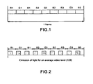
- Figure 1 shows the division of one display period of a video image, called a video frame, into a plurality of time segments each assigned to one colour component of the image.
- the video frame includes three time segments for each colour component, i.e. three segments R1, R2, R3 for the red component, three segments G1, G2, G3 for the green component, and three segments B1, B2, B3 for the blue component.
- Each red time segment is followed by a green time segment and then a blue time segment. These segments generally have substantially identical durations.
- the colour components of the video signal of the image are displayed sequentially one after the other, the colours of the pixels of the image being restored thereafter by an effect of integration (in the human eye).
- the use of a plurality of time segments for each colour component enables the emission of light to be distributed over the whole duration of the frame and to group closely together the emissions of red, green and blue light. This reduces the phenomenon of colour break-up perceived by the human eye when the emissions of different colours are far apart, for example when there is an average red emission at the beginning of the frame, an average green emission in the middle of the frame and an average blue emission at the end of the frame.
- sub-scans In the case of micromirror (DMD) projectors using binary planes to address the micromirror cells, the video frame portion associated with each colour component is divided into sub-periods, usually called sub-scans, having different durations and distributed in the various time segments associated with said colour.
- One solution for limiting colour break-up even further in this type of projector is to divide the sub-scans of longer duration into sub-scans of shorter duration and to distribute them over all the time segments of the frame to spread the emission of light even further. This results in emission of light that is distributed almost uniformly between the time segments for a given colour.
- the cells of the valve are generally addressed segment by segment using voltage control or current control to emit or to pass the same quantity of light during each segment of a given colour.
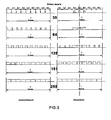
- Figure 2 shows the distribution of light emitted for a video level 128 to be displayed using an LCOS or OLED valve and a uniform distribution between the segments. The same quantity of light is emitted during each of the time segments. This results in a light emission distribution almost identical to that of DMD valve projectors when the more significant sub-scans are distributed over all the time segments of the frame.
- the present invention proposes a solution for reducing this blurring effect without creating any phenomenon of light break-up.
- the present invention relates to a method of displaying a colour video image in a sequential colour display panel including a plurality of display cells, wherein the video image to be displayed comprises a plurality of colour components and the image display period is divided into a plurality of consecutive time segments with at least three time segments assigned to each of the colour components, and wherein the video level of the pixels of the image is displayed by modulating the display time of the corresponding cells.
- the method comprises the following steps:
- the light emitted by the cells is concentrated around the reference time segment and is not spread over the entire video frame, which reduces the blurring effect without increasing the phenomenon of colour break-up, because the different colour light emissions remain very close together.
- the reference time segment is in the vicinity of the middle of the video image display period.
- the reference time segment is preferably a time segment assigned to the green component of the video signal.
- the invention also relates to a sequential colour display panel for displaying a colour video image and including a plurality of display cells, the video image to be displayed being supplied to the panel in the form of a signal comprising a plurality of colour components, wherein the image display period is divided into a plurality of consecutive time segments with at least three time segments assigned to each of the colour components and the video level of the pixels of the image is displayed by modulating the display time of the corresponding cells.
- the invention comprises means for displaying the image by giving priority to lighting the cells during a single reference time segment selected from said plurality of time segments and during the time segments closest to the reference time segment.
- the invention proposes a method in which the emission of light is concentrated on and in the vicinity of one or more reference time segments. This reduces the spreading of the emission of light in the frame and the phenomenon of break-up of the light perceived by the human eye is also very low because the emissions of light of the three colour components are very close together.
- the invention is illustrated in the case of a video frame identical to that shown in Figure 1 including three time segments for each colour.
- the invention is equally applicable to a video frame including a greater number of time segments, for example as illustrated later in the description with reference to Figure 6 .
- a single reference time segment is defined. This is advantageously a time segment associated with the green colour component because this is the most luminous colour of the three components.
- This reference time segment is generally situated at the centre of the video frame (middle of the video frame period).
- the time segment G2 is defined as the reference time segment.
- the video image is displayed by giving priority to lighting the cells of the valve during the reference time segment and the time segments closest to the reference time segment. This amounts to the same thing as selecting a triplet of reference time segments, in the present instance R2, G2 and B2.
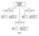
- FIG. 3 illustrates how the method of the invention is applied to the display of five video levels (30, 64, 128, 191 and 255).
- the left-hand portion of the figure represents a conventional display.
- the cells are lit for a portion of the time of the segments R2, G2, B2 situated in the vicinity of the centre of the video frame. The cells are not lit during the other time segments.
- the cells are lit throughout the central time segments R2, G2, B2 of the frame and during a portion of the time of the other segments.
- the same quantity of light is emitted on either side of an axis of symmetry situated at the centre of the reference segment and represented in chain-dotted line in the figure.
- the segments R1 and R3 are considered equidistant from the centre of the reference time segment G2.
- the cells are therefore lit for the same duration during these two time segments.
- the third red time segment before the first red time segment could be envisaged, as it is closer in time to the reference time segment.
- the first blue time segment could be lit before the third blue time segment.
- a time segment is lit only if the time segments of the same colour closest to the reference time segment are already lit.
- the time segments closest to the reference time segment do not necessarily designate the time segments closest in time to the reference time segment.
- two segments of the same colour belonging to triplets R, G, B adjacent the triplet comprising the reference time segment could equally be considered equidistant from that reference time segment and equally close to the reference time segment.
- the cells are lit throughout the time of all the time segments of the video frame as in a standard display.
- Figure 4 is a diagram showing one example of determining video level values to be displayed during each of the time segments of the frame.
- RED_8bit (respectively BLUE_8bit) is less than or equal to 85, that value is displayed in its entirety during the segment R2 (respectively B2). If it is greater than 85, the value 85 is displayed during the segment R2 (respectively B2) and a first half of the remainder is displayed during the segment R1 (respectively B1) and the second half during the segment R3 (respectively B3).
- the cell blocks the passage of light through the valve; as soon as that control voltage rises above the ramp voltage, it allows light to pass. Light is therefore emitted at the end of the segment.
- the cell In the case of the positive ramp, so long as the control voltage is greater than the voltage level of the voltage ramp, the cell allows light to pass through the valve; as soon as this control voltage falls below the ramp voltage, it blocks the passage of light. Light is therefore emitted at the beginning of the segment.
- the effect of this is to concentrate further the emission of light in the vicinity of the reference time segment and thereby to reduce further the phenomenon of light break-up.
- the second portion of the video frame advantageously displays a movement-compensated image (interpolated from the first portion of the current frame and the first portion of the next frame).
Landscapes
- Engineering & Computer Science (AREA)
- Multimedia (AREA)
- Signal Processing (AREA)
- General Physics & Mathematics (AREA)
- Theoretical Computer Science (AREA)
- Physics & Mathematics (AREA)
- Computer Hardware Design (AREA)
- Control Of Indicators Other Than Cathode Ray Tubes (AREA)
- Liquid Crystal Display Device Control (AREA)
- Control Of El Displays (AREA)
- Facsimile Image Signal Circuits (AREA)
- Color Image Communication Systems (AREA)
- Mechanical Light Control Or Optical Switches (AREA)
- Electroluminescent Light Sources (AREA)
Applications Claiming Priority (1)
| Application Number | Priority Date | Filing Date | Title |
|---|---|---|---|
| FR0550959A FR2884640A1 (fr) | 2005-04-15 | 2005-04-15 | Procede d'affichage d'une image video et panneau d'affichage mettant en oeuvre le procede |
Publications (2)
| Publication Number | Publication Date |
|---|---|
| EP1717791A1 EP1717791A1 (en) | 2006-11-02 |
| EP1717791B1 true EP1717791B1 (en) | 2015-09-30 |
Family
ID=35466448
Family Applications (1)
| Application Number | Title | Priority Date | Filing Date |
|---|---|---|---|
| EP06112528.2A Active EP1717791B1 (en) | 2005-04-15 | 2006-04-12 | Video image display method and display panel using it |
Country Status (7)
Families Citing this family (12)
| Publication number | Priority date | Publication date | Assignee | Title |
|---|---|---|---|---|
| FR2901905A1 (fr) * | 2006-05-30 | 2007-12-07 | Thomson Licensing Sas | Procede d'affichage sequentiel couleur par modulation de duree |
| TWI413961B (zh) * | 2007-06-05 | 2013-11-01 | Sony Corp | 顯示面板驅動方法、顯示裝置、顯示面板驅動裝置與電子裝置 |
| JP5309475B2 (ja) * | 2007-06-05 | 2013-10-09 | ソニー株式会社 | 表示パネル駆動方法、表示装置、表示パネル駆動装置及び電子機器 |
| US8253755B2 (en) * | 2007-09-07 | 2012-08-28 | Texas Instruments Incorporated | System and method for image-based color sequence reallocation |
| US8305387B2 (en) * | 2007-09-07 | 2012-11-06 | Texas Instruments Incorporated | Adaptive pulse-width modulated sequences for sequential color display systems |
| JP5141277B2 (ja) * | 2008-02-08 | 2013-02-13 | ソニー株式会社 | 点灯期間設定方法、表示パネルの駆動方法、バックライトの駆動方法、点灯期間設定装置、半導体デバイス、表示パネル及び電子機器 |
| JP5211732B2 (ja) | 2008-02-14 | 2013-06-12 | ソニー株式会社 | 点灯期間設定方法、表示パネルの駆動方法、点灯条件設定装置、半導体デバイス、表示パネル及び電子機器 |
| WO2012089766A1 (fr) * | 2010-12-30 | 2012-07-05 | Thomson Licensing | Procede de traitement d'un contenu video permettant l'adaptation a plusieurs types de dispositifs d'affichage |
| JP5883575B2 (ja) * | 2011-05-16 | 2016-03-15 | ピクストロニクス,インコーポレイテッド | 表示装置及びその制御方法 |
| JP2013073113A (ja) * | 2011-09-28 | 2013-04-22 | Japan Display East Co Ltd | 表示装置及びその制御方法 |
| CN106791502B (zh) * | 2017-01-23 | 2020-07-14 | 惠州Tcl移动通信有限公司 | 一种抗干扰的显示屏显示控制方法及系统 |
| US10890764B2 (en) * | 2019-03-07 | 2021-01-12 | Novatek Microelectronics Corp. | Method and system for video frame processing |
Family Cites Families (14)
| Publication number | Priority date | Publication date | Assignee | Title |
|---|---|---|---|---|
| DE69524502T2 (de) * | 1994-07-25 | 2002-06-06 | Texas Instruments Inc | Verfahren zum Reduzieren zeitlicher Artefakte in digitalen Videosystemen |
| JP2962245B2 (ja) * | 1996-10-23 | 1999-10-12 | 日本電気株式会社 | 表示装置の階調表示方法 |
| US6175355B1 (en) * | 1997-07-11 | 2001-01-16 | National Semiconductor Corporation | Dispersion-based technique for modulating pixels of a digital display panel |
| US6326980B1 (en) * | 1998-02-27 | 2001-12-04 | Aurora Systems, Inc. | System and method for using compound data words in a field sequential display driving scheme |
| JPH11327492A (ja) * | 1998-05-20 | 1999-11-26 | Mitsubishi Electric Corp | 面順次カラー画像表示装置および面順次カラー画像表示方法 |
| US6590549B1 (en) * | 1998-12-30 | 2003-07-08 | Texas Instruments Incorporated | Analog pulse width modulation of video data |
| JP3680795B2 (ja) * | 1999-09-27 | 2005-08-10 | セイコーエプソン株式会社 | 電気光学装置の駆動方法、駆動回路及び電気光学装置並びに電子機器 |
| JP2001202057A (ja) | 2000-01-21 | 2001-07-27 | Mitsubishi Electric Corp | 画像表示装置および画像表示方法 |
| EP1256924B1 (en) * | 2001-05-08 | 2013-09-25 | Deutsche Thomson-Brandt Gmbh | Method and apparatus for processing video pictures |
| JP3660610B2 (ja) * | 2001-07-10 | 2005-06-15 | 株式会社東芝 | 画像表示方法 |
| TW571280B (en) * | 2002-08-27 | 2004-01-11 | Himax Tech Inc | Driving circuit of liquid crystal cell structure and its control method |
| JP4079793B2 (ja) | 2003-02-07 | 2008-04-23 | 三洋電機株式会社 | 表示方法、表示装置およびそれに利用可能なデータ書込回路 |
| WO2004097506A2 (en) * | 2003-04-24 | 2004-11-11 | Displaytech, Inc. | Microdisplay and interface on a single chip |
| WO2005018237A1 (en) | 2003-07-30 | 2005-02-24 | Thomson Licensing S.A. | Spoke light compensation for motion artifact reduction |
-
2005
- 2005-04-15 FR FR0550959A patent/FR2884640A1/fr active Pending
-
2006
- 2006-04-07 CN CN2006100732908A patent/CN1856115B/zh active Active
- 2006-04-11 US US11/402,015 patent/US8669968B2/en active Active
- 2006-04-11 KR KR1020060032952A patent/KR101234208B1/ko active Active
- 2006-04-12 JP JP2006110184A patent/JP2006301628A/ja active Pending
- 2006-04-12 EP EP06112528.2A patent/EP1717791B1/en active Active
- 2006-04-14 TW TW095113268A patent/TW200703178A/zh unknown
Also Published As
| Publication number | Publication date |
|---|---|
| US20060232717A1 (en) | 2006-10-19 |
| FR2884640A1 (fr) | 2006-10-20 |
| EP1717791A1 (en) | 2006-11-02 |
| KR101234208B1 (ko) | 2013-02-19 |
| US8669968B2 (en) | 2014-03-11 |
| CN1856115B (zh) | 2010-05-12 |
| JP2006301628A (ja) | 2006-11-02 |
| TW200703178A (en) | 2007-01-16 |
| CN1856115A (zh) | 2006-11-01 |
| KR20060109319A (ko) | 2006-10-19 |
Similar Documents
| Publication | Publication Date | Title |
|---|---|---|
| EP1717791B1 (en) | Video image display method and display panel using it | |
| TWI791043B (zh) | 微發光二極體裝置及陣列之顯示最佳化技術 | |
| US10410570B2 (en) | Light emitting diode display device and method for improving image quality using scheme of dividing frames into subframes | |
| CN100555061C (zh) | 图像显示装置以及投影机 | |
| JP4415386B2 (ja) | 画像表示方法、画像表示処理プログラムおよび画像表示装置 | |
| JPH04366888A (ja) | 表示装置およびその動作方法 | |
| US20070064008A1 (en) | Image display system and method | |
| WO2008018113A1 (fr) | Appareil de commande de pixel et procédé de commande de pixel | |
| US20100090942A1 (en) | Active matrix display device | |
| US20080007573A1 (en) | Display device and display system employing same | |
| JPWO2002056288A1 (ja) | カラー画像表示装置 | |
| WO2015186593A1 (ja) | 表示装置 | |
| CN101013254A (zh) | 调制用于显示的图像 | |
| US9082359B2 (en) | Projection display apparatus having an optical element projecting modulated light, method for controlling the same, and electronic device | |
| US8305317B2 (en) | Method for addressing an LCD display in color sequential mode | |
| US9418598B2 (en) | Colour display | |
| JP4008178B2 (ja) | 階調表示方法 | |
| US10152909B2 (en) | Display apparatus | |
| US7471300B2 (en) | Progressive data delivery to spatial light modulators | |
| MXPA06004023A (en) | Video image display method and display panel using it | |
| JP6262940B2 (ja) | 液晶表示装置及びその駆動方法 | |
| JP2010181452A (ja) | 液晶表示装置の駆動方法 | |
| JP2004004918A (ja) | カラー液晶表示装置及びその駆動方法 | |
| TW202514578A (zh) | 用以控制微led顯示器中之影像再現之顯示器驅動器及方法 | |
| WO2010116436A1 (ja) | 駆動回路、液晶表示装置および駆動方法 |
Legal Events
| Date | Code | Title | Description |
|---|---|---|---|
| PUAI | Public reference made under article 153(3) epc to a published international application that has entered the european phase |
Free format text: ORIGINAL CODE: 0009012 |
|
| AK | Designated contracting states |
Kind code of ref document: A1 Designated state(s): AT BE BG CH CY CZ DE DK EE ES FI FR GB GR HU IE IS IT LI LT LU LV MC NL PL PT RO SE SI SK TR |
|
| AX | Request for extension of the european patent |
Extension state: AL BA HR MK YU |
|
| 17P | Request for examination filed |
Effective date: 20070425 |
|
| AKX | Designation fees paid |
Designated state(s): DE FR GB |
|
| RAP1 | Party data changed (applicant data changed or rights of an application transferred) |
Owner name: THOMSON LICENSING |
|
| GRAP | Despatch of communication of intention to grant a patent |
Free format text: ORIGINAL CODE: EPIDOSNIGR1 |
|
| INTG | Intention to grant announced |
Effective date: 20150109 |
|
| GRAP | Despatch of communication of intention to grant a patent |
Free format text: ORIGINAL CODE: EPIDOSNIGR1 |
|
| INTG | Intention to grant announced |
Effective date: 20150508 |
|
| GRAS | Grant fee paid |
Free format text: ORIGINAL CODE: EPIDOSNIGR3 |
|
| GRAA | (expected) grant |
Free format text: ORIGINAL CODE: 0009210 |
|
| AK | Designated contracting states |
Kind code of ref document: B1 Designated state(s): DE FR GB |
|
| REG | Reference to a national code |
Ref country code: GB Ref legal event code: FG4D |
|
| REG | Reference to a national code |
Ref country code: DE Ref legal event code: R096 Ref document number: 602006046782 Country of ref document: DE |
|
| REG | Reference to a national code |
Ref country code: FR Ref legal event code: PLFP Year of fee payment: 11 |
|
| REG | Reference to a national code |
Ref country code: DE Ref legal event code: R097 Ref document number: 602006046782 Country of ref document: DE |
|
| PLBE | No opposition filed within time limit |
Free format text: ORIGINAL CODE: 0009261 |
|
| STAA | Information on the status of an ep patent application or granted ep patent |
Free format text: STATUS: NO OPPOSITION FILED WITHIN TIME LIMIT |
|
| 26N | No opposition filed |
Effective date: 20160701 |
|
| REG | Reference to a national code |
Ref country code: FR Ref legal event code: PLFP Year of fee payment: 12 |
|
| REG | Reference to a national code |
Ref country code: DE Ref legal event code: R082 Ref document number: 602006046782 Country of ref document: DE Representative=s name: DEHNS, DE Ref country code: DE Ref legal event code: R082 Ref document number: 602006046782 Country of ref document: DE Representative=s name: DEHNS PATENT AND TRADEMARK ATTORNEYS, DE Ref country code: DE Ref legal event code: R082 Ref document number: 602006046782 Country of ref document: DE Representative=s name: HOFSTETTER, SCHURACK & PARTNER PATENT- UND REC, DE |
|
| REG | Reference to a national code |
Ref country code: FR Ref legal event code: PLFP Year of fee payment: 13 |
|
| REG | Reference to a national code |
Ref country code: DE Ref legal event code: R082 Ref document number: 602006046782 Country of ref document: DE Representative=s name: DEHNS, DE Ref country code: DE Ref legal event code: R081 Ref document number: 602006046782 Country of ref document: DE Owner name: INTERDIGITAL CE PATENT HOLDINGS SAS, FR Free format text: FORMER OWNER: THOMSON LICENSING, ISSY-LES-MOULINEAUX, FR Ref country code: DE Ref legal event code: R082 Ref document number: 602006046782 Country of ref document: DE Representative=s name: DEHNS PATENT AND TRADEMARK ATTORNEYS, DE |
|
| REG | Reference to a national code |
Ref country code: GB Ref legal event code: 732E Free format text: REGISTERED BETWEEN 20190926 AND 20191002 |
|
| PGFP | Annual fee paid to national office [announced via postgrant information from national office to epo] |
Ref country code: DE Payment date: 20250428 Year of fee payment: 20 |
|
| PGFP | Annual fee paid to national office [announced via postgrant information from national office to epo] |
Ref country code: GB Payment date: 20250422 Year of fee payment: 20 |
|
| PGFP | Annual fee paid to national office [announced via postgrant information from national office to epo] |
Ref country code: FR Payment date: 20250424 Year of fee payment: 20 |