EP1716740A1 - Schneidwerk - Google Patents
Schneidwerk Download PDFInfo
- Publication number
- EP1716740A1 EP1716740A1 EP06002260A EP06002260A EP1716740A1 EP 1716740 A1 EP1716740 A1 EP 1716740A1 EP 06002260 A EP06002260 A EP 06002260A EP 06002260 A EP06002260 A EP 06002260A EP 1716740 A1 EP1716740 A1 EP 1716740A1
- Authority
- EP
- European Patent Office
- Prior art keywords
- cutting unit
- bearing
- unit according
- support
- bracket
- Prior art date
- Legal status (The legal status is an assumption and is not a legal conclusion. Google has not performed a legal analysis and makes no representation as to the accuracy of the status listed.)
- Granted
Links
Images



Classifications
-
- A—HUMAN NECESSITIES
- A01—AGRICULTURE; FORESTRY; ANIMAL HUSBANDRY; HUNTING; TRAPPING; FISHING
- A01D—HARVESTING; MOWING
- A01D57/00—Delivering mechanisms for harvesters or mowers
- A01D57/01—Devices for leading crops to the mowing apparatus
- A01D57/02—Devices for leading crops to the mowing apparatus using reels
Definitions
- the invention relates to a cutting unit of a combine harvester according to the preamble of claim 1.
- a reel for a combine harvester in which the star-shaped arranged reel spokes each consist of a base body and a counterpart, the base body and counterpart are each provided with an open bore. Between the base body and the counterpart is firmly clamped in a two-piece, made of plastic bearing shell, which rotatably and pivotally receives the support beam. In order to limit the axial movement of the support beam in the bearing shells, the support beams are penetrated immediately adjacent to the bearing shells of pins whose abutment projecting from the support tube ends to the camp as soon as the support tube moves axially in the bearing shell.
- the invention is therefore based on the object to avoid the disadvantages of the prior art and in particular to develop a reel, in which the risk of wrapping with crop is reduced.
- each bearing is formed by at least one bearing, wherein the bearing comprises at least one integrated axial fixation, the axial stops are outside of the crop flow, so that the winding tendency is considerably reduced or avoided altogether.
- a first integrated axial fixation secures the support beam within the bearing, whereby a compact design is achieved.
- a particularly advantageous embodiment is obtained when a first integrated axial fixation connects the support beam with a bush which is arranged on the support beam, so that no projecting edges are present on the bushing and on the support beam in the region of the bearings.
- the second integrated axial fixation secures the bush in a bearing housing, wherein the sleeve is rotatably mounted in the bearing housing, the support beam can rotate in the bearing and is simultaneously held axially immovable in the camp.
- the first integrated axial fixation consists of at least one cam which is arranged in a recess of the bush, wherein the recess in the bushing corresponds to the cross section of the support beam and the support beam has at least one bore into which the Cam engages.
- the socket includes the element for axially fixing the socket on the support beam.
- the cam is retractable, so that the support tube can be inserted into the recess of the socket.
- the bush Due to the fact that the bush consists of at least two sub-elements, which are hinged and / or divisible, the bushing can radially around the Support tube to be mounted. This has the particular advantage that the sockets are easy to install and disassemble on the support tube.
- the sub-elements of the socket are connected at one end via a joint and the other end via a closure. This has the advantage that the sub-elements are connected in the unfolded state via the joint, whereby the assembly and disassembly work is simplified.
- the first integrated axial fixation on a pin which at least partially penetrates the socket and at least partially the support beam, so that in a simple manner a positive connection is made.
- the socket can be flush with the bearing housing, the second integrated axial fixation of a arranged on the bush, circumferential annular groove and arranged on the bearing housing Fixiersteg is formed, wherein the Fixiersteg engages in the annular groove of the socket.
- crops are prevented from entering the space between the bushing and the bearing housing.
- the bearing housing comprises a bearing shell and a bracket, wherein the bearing shell and the bracket are connected to each other, so that the bearing housing can be mounted radially around the socket.
- a particularly advantageous embodiment is obtained when the bearing shell has resilient holding elements and the support or control star corresponding openings into which engage the resilient holding elements of the bearing shell, so that the holding elements are fixed to the support and control stars and the support beam with the sockets in the bearing shells can be inserted. In this way, a simple mounting of the support beam on the support and control stars is possible.
- the support or control star has bends and the bracket inserted between the bearing shell and the folds of the support or control star is, the bearing housing in the circumferential direction of the reel is positively connected to the support or control star.
- the bracket and the bearing shell via at least one screw connection are connected to each other.
- the bracket can be postpone when assembling the bearing housing on the bearing shell without twisting, projections on both sides and grooves are arranged on the bearing shell on both sides of the bracket, which together result in guides between the bracket and the bearing shell.
- the bush and / or the bearing housing are manufactured as an injection molded part, so that the bearing can be produced inexpensively.
- the bearing is advantageously made of plastic, it has a high self-weight with high stability and at the same time has good sliding properties.
- an agricultural machine 2 designed as a self-propelled harvester 1 is shown in side view during harvesting.
- the combine harvester 1 has a vertically pivotable intake shaft 3, on which a receiving attachment 5 designed as a cutting mechanism 4 is arranged.
- the cutting unit 4 is adjustable to a desired cutting height 6.
- the cutting unit 4 consists of a cutting table 7 and a fixed to the cutting table 7 rotatably driven reel 8, wherein the reel 8 relative to the cutting table 7 is adjustable in height and adjustable in the horizontal direction.
- the crop 9 to be harvested is cut off with a cutter bar 10 arranged at the front edge of the cutting table 7, and the cut crop 11 is then conveyed by means of the reel 8 to a rotationally driven auger 12 arranged in the cutting table 7.
- the auger 12 leads the crop 11 to the intake shaft 3.
- a feeder 13 passes, which transfers the crop 11 to the threshing unit 14.
- FIG. 2 shows a detail of a reel 8 shown in perspective.
- a plurality of support stars 19 are fastened at regular intervals on a reel shaft 15.
- a plurality of supporting beams 21 are rotatably or pivotably arranged in bearings 20, which will be explained in more detail later on, which extend continuously over the entire width of the reel 8.
- a plurality of conveyor tines 22 are arranged uniformly spaced, which are fixedly connected to the support beam 21.
- the support beams 21 are coupled to a control star 23, which is mounted rotatably on the reel shaft 15 via a roller bearing 27.
- the support stars 19 are arranged centrally on the reel shaft 15, while the control star 23 eccentrically on the reel shaft 15 is stored.
- the coupling of the support beam 21 with the control star 23 is such that each support beam 21 has a crank 24 with an offset 25, the free end is rotatably mounted in each case in a bearing 26 on the circumference of the control stem 23.
- the pivoting angle of each supporting beam 21 and thus the orientation of the attached to the respective supporting beam 21 feed tines 22 is dependent on the instantaneous angle of rotation of the reel 8.
- control star 23 can be rotated by means of a control lever 12 mounted on the hand lever 29 on the reel shaft 15 in a desired position and determined by means of a locking device 30 in this position.
- a control lever 12 mounted on the hand lever 29 on the reel shaft 15 in a desired position and determined by means of a locking device 30 in this position.
- the effectiveness of the promotion of the crop is influenced by the conveyor tines 22.
- the bearing 20 comprises a first integrated axial fixing 16, which connects the support beam 21 with the bush 33.
- the first integrated axial fixing 16 consists of two arranged in the recess 32 cams 34, 35 which engage in corresponding holes 36, 37 in the support beam 21, so that the sleeve 33 secured within the bearing 20 against axial displacement and rotation on the support beam 21 becomes.
- the sub-elements 58, 59 are provided at one end with a hinge 41 and at the other end with a closure 42.
- the bushing 33 consists of two sub-elements which are connected to each other via closures.
- the above-mentioned embodiments of the bushing 33 can be mounted radially around the support shaft 21 and are therefore individually interchangeable.
- the cams 34, 35 are retractable, so that the bushes 33 are pushed onto the support beams 21.
- the bush 33 itself is rotatably mounted in a bearing housing 38, which is secured to the support star 19.
- a second integrated axial fixing 17 secures the bush 33 in the bearing housing 38 and thus the support beam 21 within the bearing 20, whereby the stability of the reel 8 is increased.
- the second integrated axial fixation 17 according to the invention is formed from a peripheral ring groove 39 arranged on the bushing 33 and the fixing webs 40, 51 arranged on the bearing housing 38, which engage in the annular groove 39 of the bushing.
- the second integrated axial fixation 17 has the advantage that the bushing 33 is flush with the bearing housing 38, so that the bearing 20 has no protruding or recessed edges, whereby penetration of crop between bushing 33 and bearing housing 38 is avoided.
- the bearing housing 38 is designed in two parts as shown in Fig. 4 and consists of a bearing shell 43 and a bracket 44.
- the bearing shell 43 has two resilient retaining elements 45 which engage in corresponding openings 46 on the support or control star 19, 23 to the First bearing shell 43 to fix the support star 19.
- the support beam 21 with the bushings 33 attached thereto is inserted into the bearing shells 43 fixed to the support stars 19.
- a respective bracket 44 is inserted via the bush 33 between the bearing shell 43 and the folds 47 of the support star 19 to close the bearing housing 38 and to connect the bearing 20 in the circumferential direction positively with the support star 19.
- the bracket 44 is guided when pushed, guides 48 are arranged on both sides between the bearing shell 43 and the bracket 44, which are each formed of grooves 49 on the bearing shell 43 and a corresponding fixing web 40 on the bracket 44.
- the Fixiersteg 40 abuts the end of the grooves 48 against a stop 52, which determines the position of the bracket 44 with the bearing 20 closed.
- the support star 19, the bearing shell 43 and the bracket 44 are via two screw connections 53 connected to each other, on the one hand secure the bracket 44 on the bearing shell 43 and at the same time connect the bearing housing 38 with the support star 19.
- the width 54 of the bearing shell 43 of the support stars 19, the width 55 of the bushing 33 and the width 56 of the bearing housing 38 are equal and all three components are arranged in alignment with each other, also forms the bracket 44 of the bearing housing 38 together with the folds 47 of the support star 19th an approximately continuous outer contour 57, so that no protruding edges are present on the circumference of the support star 19, where crop can adhere.
- the bearing 26 on the control star 23 may be constructed identical to the bearing 20 on the support star 19, so that the bush 33 and the bearing housing can also be used to support the free end of the crank 24 of the support beam 21.
- bearing 20, 26 are inexpensive to produce when the bushing 33 and the bearing housing 38 are preferably made as an injection molded part.
- the bearings 20, 26 have a low weight and good sliding properties
- the bushing 33 and the bearing housing 38 are preferably made of plastic.
- the first integrated fixation 16 comprises a pin 60 which penetrates a closed, pushed onto the support bar 21 sleeve 33 and the support beam 21 and positively connects with each other, wherein the pin 60 is not protrudes beyond the sleeve 33.
Landscapes
- Life Sciences & Earth Sciences (AREA)
- Environmental Sciences (AREA)
- Outside Dividers And Delivering Mechanisms For Harvesters (AREA)
- Harvester Elements (AREA)
Abstract
Description
- Die Erfindung betrifft ein Schneidwerk eines Mähdreschers nach dem Oberbegriff des Anspruchs 1.
- Aus dem GM 77 02 807 ist eine Haspel für einen Mähdrescher offenbart, bei der die sternförmig angeordneten Haspelspeichen jeweils aus einem Grundkörper und einem Gegenstück bestehen, wobei Grundkörper und Gegenstück jeweils mit einer offenen Bohrung versehen sind. Zwischen dem Grundkörper und dem Gegenstück ist in eine zweiteilige, aus Kunststoff gefertigte Lagerschale fest eingeklemmt, die den Tragbalken dreh- und schwenkbeweglich aufnimmt.
Um die axiale Bewegung des Tragbalkens in den Lagerschalen zu begrenzen, werden die Tragbalken unmittelbar neben den Lagerschalen von Stiften durchsetzt, deren aus dem Tragrohr vorstehende Enden an die Lager anstoßen, sobald das Tragrohr sich axial in der Lagerschale bewegt. - Nachteilig bei dieser Lagerung der Haspelrechen ist, dass das Erntegut am äußeren Umfang der Haspel an den vorstehenden Enden der Stifte eingeklemmt und anschließend um die Haspel gewickelt wird.
- Der Erfindung liegt daher die Aufgabe zugrunde die Nachteile des Standes der Technik zu vermeiden und insbesondere eine Haspel zu entwickeln, bei der die Gefahr des Umwickelns mit Erntegut reduziert wird.
- Diese Aufgabe wird erfindungsgemäß durch die kennzeichnenden Merkmale des Anspruchs 1 gelöst. Weitere vorteilhafte Wirkungen des Erfindungsgegenstandes ergeben sich aus den Unteransprüchen.
- Dadurch, dass jede Lagerung von zumindest einem Lager gebildet wird, wobei das Lager wenigstens eine integrierte axiale Fixierung umfasst, sind die axialen Anschläge außerhalb des Gutflusses, so dass die Wickelneigung erheblich reduziert oder ganz vermieden wird.
- In vorteilhafter Ausgestaltung der Erfindung sichert eine erste integrierte axiale Fixierung den Tragbalken innerhalb des Lagers, wodurch eine kompakte Bauweise erreicht wird.
- Eine besonders vorteilhafte Ausgestaltung ergibt sich, wenn eine erste integrierte axiale Fixierung den Tragbalken mit einer Buchse verbindet, die auf dem Tragbalken angeordnet ist, so dass an der Buchse sowie an dem Tragbalken im Bereich der Lager keine vorstehenden Kanten vorhanden sind.
- Indem die zweite integrierte axiale Fixierung die Buchse in einem Lagergehäuse sichert, wobei die Buchse in dem Lagergehäuse drehbar gelagert ist, kann sich der Tragbalken im Lager drehen und wird gleichzeitig im Lager axial unverschieblich gehalten.
- Eine besonders vorteilhafte Ausgestaltung ergibt sich, wenn die erste integrierte axiale Fixierung aus wenigstens einem Nocken besteht, der in einer Ausnehmung der Buchse angeordnet ist, wobei die Ausnehmung in der Buchse dem Querschnitt des Tragbalkens entspricht und der Tragbalken wenigstens eine Bohrung aufweist, in die der Nocken eingreift. Dies hat vor allem den Vorteil, dass die Buchse das Element zur axialen Fixierung der Buchse auf dem Tragbalken beinhaltet.
- In vorteilhafter Ausgestaltung der Erfindung ist der Nocken versenkbar, damit das Tragrohr in die Ausnehmung der Buchse eingeschoben werden kann.
- Dadurch, dass die Buchse aus zumindest zwei Teilelementen besteht, die aufklappbar und/oder teilbar miteinander verbunden sind, kann die Buchse radial um das Tragrohr montiert werden. Das hat insbesondere den Vorteil, dass die Buchsen einfach auf dem Tragrohr montierbar und demontierbar sind.
- In vorteilhafter Ausgestaltung sind die Teilelemente der Buchse einends über ein Gelenk und andernends über einen Verschluss miteinander verbunden. Dies hat den Vorteil, dass die Teilelemente im aufgeklappten Zustand über das Gelenk verbunden sind, wodurch die Montage- und Demontagearbeit vereinfacht wird.
- In einer alternativen Ausführung der Erfindung weist die erste integrierte axiale Fixierung einen Stift auf, der zumindest teilweise die Buchse und zumindest teilweise den Tragbalken durchdringt, so dass auf einfache Weise eine formschlüssige Verbindung hergestellt ist.
- Damit die Buchse bündig mit dem Lagergehäuse abschließen kann, ist die zweite integrierte axiale Fixierung aus einer an der Buchse angeordneten, umlaufenden Ringnut und einer an dem Lagergehäuse angeordneten Fixiersteg gebildet, wobei der Fixiersteg in die Ringnut der Buchse eingreift. Bei dieser Anordnung wird verhindert, dass Erntegut in den Raum zwischen Buchse und Lagergehäuse eindringt.
- In vorteilhafter Weiterbildung der Erfindung umfasst das Lagergehäuse eine Lagerschale und einen Bügel, wobei die Lagerschale und der Bügel miteinander verbunden werden, so dass das Lagergehäuse radial um die Buchse montiert werden kann.
- Eine besonders vorteilhafte Ausgestaltung ergibt sich, wenn die Lagerschale federnde Halteelemente und der Trag- oder Steuerstern entsprechende Öffnungen aufweist, in die die federnden Halteelemente der Lagerschale einrasten, so dass die Halteelemente an den Trag- und Steuersternen fixierbar sind und der Tragbalken mit den Buchsen in die Lagerschalen einlegbar ist. Auf diese Weise ist eine einfache Montage des Tragbalkens an den Trag- und Steuersternen möglich.
- Dadurch, das der Trag- oder Steuerstern Abkantungen aufweist und der Bügel zwischen die Lagerschale und den Abkantungen des Trag- oder Steuersterns eingeschoben wird, ist das Lagergehäuse in Umfangsrichtung der Haspel formschlüssig mit dem Trag- oder Steuerstern verbunden.
- Um das Lagergehäuse an dem Trag- oder Steuerstern zu befestigen und gleichzeitig den Bügel an der Lagerschale zu sichern sind der Trag- oder Steuerstern, der Bügel und die Lagerschale über wenigstens eine Schraubenverbindung miteinander verbunden.
- Damit sich der Bügel beim Zusammenfügen des Lagergehäuses auf die Lagerschale aufschieben lässt ohne dabei zu verdrehen, sind an dem Bügel beidseitig Vorsprünge und an der Lagerschale beidseitig Nuten angeordnet, die zusammen Führungen zwischen dem Bügel und der Lagerschale ergeben.
- Vorteilhafterweise werden die Buchse und/oder das Lagergehäuse als Spritzgussteil gefertigt, so dass das Lager kostengünstig herstellbar ist.
- Dadurch, dass das Lager vorteilhafterweise aus Kunststoff gefertigt wird, weist es bei hoher Stabilität ein geringes Eigengewicht auf und besitzt gleichzeitig gute Gleiteigenschaften.
- Weitere vorteilhafte Ausgestaltungen sind Gegenstand weiterer Unteransprüche und werden nachfolgend an Hand eines in mehreren Figuren dargestellten Ausführungsbeispiels näher erläutert.
- Es zeigen:
- Fig.1
- eine schematische Seitenansicht eines Mähdreschers,
- Fig.2
- einen Ausschnitt einer perspektivischen Ansicht einer Haspel,
- Fig.3
- eine Seitenansicht des Lagers,
- Fig.4
- eine perspektivische Ansicht des Lagers,
- Fig. 5
- eine perspektivische Ansicht einer zweiten Ausführung der erfindungsgemäßen Fixierung.
- In der Fig.1 ist eine als selbstfahrender Mähdrescher 1 ausgeführte landwirtschaftliche Arbeitsmaschine 2 in der Seitenansicht während der Erntefahrt dargestellt. Frontseitig weist der Mähdrescher 1 einen vertikal schwenkbaren Einzugsschacht 3 auf, an dem ein als Schneidwerk 4 ausgeführter Aufnahmevorsatz 5 angeordnet ist. Mit dem schwenkbaren Einzugsschacht 3 ist das Schneidwerk 4 auf eine gewünschte Schneidwerkshöhe 6 einstellbar. Das Schneidwerk 4 besteht aus einem Schneidtisch 7 und aus einer an dem Schneidtisch 7 befestigten rotierend angetriebenen Haspel 8, wobei die Haspel 8 gegenüber dem Schneidtisch 7 höhenverstellbar und in horizontaler Richtung verstellbar ist. Das zu erntende Erntegut 9 wird mit einem an der vorderen Kante des Schneidtischs 7 angeordneten Messerbalken 10 abgeschnitten und das geschnittene Erntegut 11 anschließend mit Hilfe der Haspel 8 zu einer im Schneidtisch 7 angeordneten, rotierend angetriebenen Einzugsschnecke 12 gefördert. Die Einzugsschnecke 12 führt das Erntegut 11 dem Einzugsschacht 3 zu. In dem Einzugsschacht 3 läuft ein Schrägförderer 13, der das Erntegut 11 an das Dreschwerk 14 übergibt.
- Fig.2 zeigt einen Ausschnitt einer perspektivisch dargestellten Haspel 8. Auf einer Haspelwelle 15 sind in gleichmäßigen Abständen mehrere Tragsterne 19 befestigt. Am Umfang der Tragsterne 19 sind in, an späterer Stelle noch näher erläuterten Lagern 20 drehbar bzw. schwenkbar mehrere Tragbalken 21 angeordnet, die sich durchgehend über die gesamte Breite der Haspel 8 erstrecken. An diesen Tragbalken 21 sind mehrere Förderzinken 22 gleichmäßig beabstandet angeordnet, die fest mit dem Tragbalken 21 verbunden sind. Damit die Tragbalken 21 mit den daran starr angebrachten Förderzinken 22 beim Umlauf der Haspel 8 verschwenken, sind die Tragbalken 21 an einen Steuerstern 23 gekoppelt, der über ein Rollenlager 27 drehbar auf der Haspelwelle 15 gelagert ist. Die Tragsterne 19 sind zentrisch auf der Haspelwelle 15 angeordnet, während der Steuerstern 23 exzentrisch auf der Haspelwelle 15 gelagert ist. Die Koppelung des Tragbalkens 21 mit dem Steuerstern 23 erfolgt derart, dass jeder Tragbalken 21 eine Kurbel 24 mit einem Versatz 25 aufweist, deren freies Ende jeweils in einem Lager 26 am Umfang des Steuersterns 23 drehbar gelagert ist. Der Schwenkwinkel jedes Tragbalkens 21 und damit die Ausrichtung der an dem jeweiligen Tragbalken 21 befestigten Förderzinken 22 ist abhängig von dem momentanen Drehwinkel der Haspel 8. Um die Bewegungsbahn der Förderzinken 22 und damit ihre jeweils zu einem bestimmten Drehwinkel der Haspel 8 zugehörige Ausrichtung zu verändern, kann der Steuerstern 23 mittels eines am Steuerstern 12 angebrachten Handhebels 29 auf der Haspelwelle 15 in eine gewünschte Lage gedreht und mit Hilfe einer Feststellvorrichtung 30 in dieser Lage festgestellt werden. Je nach dem, mit welcher Neigung die Förderzinken 22 in das Erntegut eingreifen bzw. aus dem Erntegut herausgleiten, wird die Effektivität der Förderung des Ernteguts durch die Förderzinken 22 beeinflusst.
- Fig.3 zeigt eine Seitenansicht des Lagers 20 in dem der Tragbalken 21 an dem Tragstern 19 gelagert ist. Der Tragbalken 21 besteht aus einem ungleichförmigen Hohlprofil 31, welches eine entsprechende Ausnehmung 32 einer zylinderförmigen Buchse 33 durchdringt. Das Lager 20 umfasst erfindungsgemäß eine erste integrierte axiale Fixierung 16, die den Tragbalken 21 mit der Buchse 33 verbindet. Die erste integrierte axiale Fixierung 16 besteht aus zwei in der Ausnehmung 32 angeordneten Nocken 34, 35, die in entsprechende Bohrungen 36, 37 im Tragbalken 21 eingreifen, so dass die Buchse 33 innerhalb des Lagers 20 gegen axiales Verschieben und Verdrehen auf dem Tragbalken 21 gesichert wird.
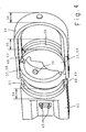
Um die Buchse 33 auf dem Tragbalken 21 zu montieren, besteht diese wie in Fig. 4 dargestellt aus zwei Teilelementen 58, 59, die aufklappbar miteinander verbunden sind. Hierzu sind die Teilelemente 58, 59 einends mit einem Gelenk 41 und andernends mit einem Verschluss 42 versehen.
Es ist jedoch auch eine Ausführung denkbar, bei der die Buchse 33 aus zwei Teilelementen besteht, die über Verschlüsse miteinander verbindbar sind. Die oben genannten Ausführungen der Buchse 33 können radial um die Tragachse 21 angebracht werden und sind deshalb einzeln auswechselbar. Es ist jedoch ebenso eine Ausführung der Buchse 33 vorstellbar, bei der die Nocken 34, 35 versenkbar sind, so dass die Buchsen 33 auf die Tragbalken 21 aufschiebbar sind. - Die Buchse 33 selbst ist in einem Lagergehäuse 38 drehbar gelagert, welches am Tragstern 19 befestigt ist. Eine zweite integrierte axiale Fixierung 17 sichert die Buchse 33 in dem Lagergehäuse 38 und somit den Tragbalken 21 innerhalb des Lagers 20, wodurch die Stabilität der Haspel 8 erhöht wird.
Die zweite erfindungsgemäße integrierte axiale Fixierung 17 wird aus einer an der Buchse 33 angeordneten, umlaufenden Ringnut 39 und den an dem Lagergehäuse 38 angeordneten Fixierstege 40, 51 gebildet, die in die Ringnut 39 der Buchse eingreifen. - Die zweite integrierte axiale Fixierung 17 hat den Vorteil, das die Buchse 33 bündig mit dem Lagergehäuse 38 abschließt, so dass das Lager 20 keine vor- oder zurückspringende Kanten aufweist, wodurch ein Eindringen von Erntegut zwischen Buchse 33 und Lagerhäuse 38 vermieden wird.
- Das Lagergehäuse 38 ist wie in Fig. 4 dargestellt zweiteilig ausgeführt und besteht aus einer Lagerschale 43 und einem Bügel 44. Die Lagerschale 43 weist zwei federnde Halteelemente 45 auf, die in entsprechende Öffnungen 46 am Trag- oder Steuerstern 19, 23 einrasten, um die Lagerschale 43 zunächst am Tragstern 19 zu fixieren. Der Tragbalken 21 mit den daran befestigten Buchsen 33 wird in die an den Tragsternen 19 fixierten Lagerschalen 43 eingelegt. Anschließend wird jeweils ein Bügel 44 über die Buchse 33 zwischen der Lagerschale 43 und den Abkantungen 47 des Tragsterns 19 eingeschoben, um das Lagergehäuse 38 zu verschließen und das Lager 20 in Umfangsrichtung formschlüssig mit dem Tragstern 19 zu verbinden. Damit der Bügel 44 beim Aufschieben geführt wird, sind zwischen der Lagerschale 43 und dem Bügel 44 beidseitig Führungen 48 angeordnet, die jeweils aus Nuten 49 an der Lagerschale 43 und einem entsprechenden Fixiersteg 40 an dem Bügel 44 gebildet werden. Der Fixiersteg 40 stößt am Ende der Nuten 48 gegen einen Anschlag 52, der die Lage des Bügels 44 bei geschlossenem Lager 20 vorgibt. Der Tragstern 19, die Lagerschale 43 und der Bügel 44 werden über zwei Schraubenverbindungen 53 miteinander verbunden, die einerseits den Bügel 44 an der Lagerschale 43 sichern und gleichzeitig das Lagergehäuse 38 mit dem Tragstern 19 verbinden.
- Die Breite 54 der Lagerschale 43 der Tragsterne 19, die Breite 55 der Buchse 33 sowie die Breite 56 des Lagergehäuses 38 sind gleich und alle drei Bauteile sind zueinander fluchtend angeordnet, zudem bildet der Bügel 44 des Lagergehäuses 38 zusammen mit den Abkantungen 47 des Tragsterns 19 eine annähernd stufenlose Außenkontur 57, so dass am Umfang des Tragsterns 19 keine vorstehenden Kanten vorhanden sind, an denen Erntegut anhaften kann.
- Das Lager 26 am Steuerstern 23 kann baugleich zu dem Lager 20 am Tragstern 19 ausgeführt sein, so dass die Buchse 33 und das Lagergehäuse ebenfalls dazu verwendet werden können, um das freie Ende der Kurbel 24 des Tragbalkens 21 zu lagern.
- Die in großer Stückzahl benötigten Lager 20, 26 sind kostengünstig herstellbar, wenn die Buchse 33 und das Lagergehäuse 38 vorzugsweise als Spritzgussteil gefertigt werden.
- Damit die Lager 20, 26 ein geringes Eigengewicht und gute Gleiteigenschaften aufweisen, sind die Buchse 33 und das Lagergehäuse 38 vorzugsweise aus Kunststoff gefertigt.
- Es ist ebenso eine erfindungsgemäße Ausführung gemäß Fig. 5 vorstellbar, bei der die erste integrierte Fixierung 16 einen Stift 60 umfasst, der eine geschlossene, auf den Tragbalken 21 aufgeschobene Hülse 33 und den Tragbalken 21 durchdringt und formschlüssig miteinander verbindet, wobei der Stift 60 nicht über die Hülse 33 übersteht.
- Es liegt im Rahmen des Könnens eines Fachmannes die beschriebenen Ausführungsbeispiele in nicht dargestellter Weise abzuwandeln oder in anderen Maschinensystemen einzusetzen, um die beschriebenen Effekte zu erzielen, ohne dabei den Rahmen der Erfindung zu verlassen.
-
- 1
- Mähdrescher
- 2
- Landw. Arbeitsmaschine
- 3
- Einzugsschacht
- 4
- Schneidwerk
- 5
- Aufnahmevorsatz
- 6
- Schneidwerkshöhe
- 7
- Schneidtisch
- 8
- Haspel
- 9
- Erntegut
- 10
- Messerbalken
- 11
- Erntegut
- 12
- Einzugsschnecke
- 13
- Schrägförderer
- 14
- Dreschwerk
- 15
- Haspelwelle
- 16
- erste integrierte axiale Fixierung
- 17
- zweite integrierte axiale Fixierung
- 18
- 19
- Tragsterne
- 20
- Lager
- 21
- Tragbalken
- 22
- Förderzinken
- 23
- Steuerstern
- 24
- Kröpfung
- 25
- Versatz
- 26
- Lager
- 27
- Rollenlager
- 28
- Feststellvorrichtung
- 29
- Handhebel
- 30
- Feststellvorrichtung
- 31
- Hohlprofil
- 32
- Ausnehmung
- 33
- Buchse
- 34
- Nocken
- 35
- Nocken
- 36
- Bohrung
- 37
- Bohrung
- 38
- Lagergehäuse
- 39
- Ringnut
- 40
- Fixiersteg
- 41
- Gelenk
- 42
- Verschluss
- 43
- Lagerschale
- 44
- Bügel
- 45
- Halteelement
- 46
- Öffnungen
- 47
- Abkantungen
- 48
- Führungen
- 49
- Nuten
- 50
- 51
- Fixiersteg
- 52
- Anschlag
- 53
- Schraubenverbindung
- 54
- Breite
- 55
- Breite
- 56
- Breite
- 57
- stufenlose Außenkontur
- 58
- Teilelement
- 59
- Teilelement
- 60
- Stift
Claims (17)
- Schneidwerk eines Mähdreschers (1) mit einer Haspel (8), wobei die Haspel (8) im Wesentlichen aus mehreren mit Abstand zueinander angeordneten Trag- und Steuersternen (19, 23) und wenigstens einem Tragbalken (21) besteht, wobei der Tragbalken (21) im Bereich der Trag- und Steuersterne (19, 23) in Lagerungen fixiert ist,
dadurch gekennzeichnet,
dass jede Lagerung von zumindest einem Lager (20, 26) gebildet wird, wobei das Lager (20, 26) wenigstens eine integrierte axiale Fixierung (16, 17) umfasst. - Schneidwerk nach Anspruch 1,
dadurch gekennzeichnet,
dass eine erste integrierte axiale Fixierung (16) den Tragbalken (21) innerhalb des Lagers (20, 26) axial sichert. - Schneidwerk nach wenigstens einem der vorhergehenden Ansprüche,
dadurch gekennzeichnet,
dass die erste integrierte axiale Fixierung (16) den Tragbalken (21) mit einer Buchse (33) verbindet, die auf dem Tragbalken (21) angeordnet ist. - Schneidwerk nach wenigstens einem der vorhergehenden Ansprüche,
dadurch gekennzeichnet,
dass eine zweite integrierte axiale Fixierung (17) die Buchse (33) in einem Lagergehäuse (38) sichert, wobei die Buchse (33) in dem Lagergehäuse (38) drehbar gelagert ist.. - Schneidwerk nach wenigstens einem der vorhergehenden Ansprüche,
dadurch gekennzeichnet,
dass die erste integrierte axiale Fixierung (16) aus wenigstens einem Nocken (34, 35) besteht, der in einer Ausnehmung (32) der Buchse (33) angeordnet ist, wobei die Ausnehmung (32) in der Buchse (33) dem Querschnitt des Tragbalkens (21) entspricht und der Tragbalken (21) wenigstens eine Bohrung (36, 37) aufweist, in die der Nocken (34, 35) eingreift. - Schneidwerk nach wenigstens einem der vorhergehenden Ansprüche,
dadurch gekennzeichnet,
dass der Nocken (34, 35) versenkbar ist. - Schneidwerk nach wenigstens einem der vorhergehenden Ansprüche,
dadurch gekennzeichnet,
dass die Buchse (33) aus zumindest zwei Teilelementen (58, 59) besteht, die aufklappbar und/oder teilbar miteinander verbunden sind. - Schneidwerk nach wenigstens einem der vorhergehenden Ansprüche,
dadurch gekennzeichnet,
dass die Teilelemente (58, 59) der Buchse (33) einends über ein Gelenk (41) und andernends über einen Verschluss (42) miteinander verbunden sind. - Schneidwerk nach wenigstens einem der vorhergehenden Ansprüche,
dadurch gekennzeichnet,
dass die erste integrierte axiale Fixierung (16) einen Stift (60) umfasst, der zumindest teilweise die Buchse (33) und zumindest teilweise den Tragbalken (21) durchdringt. - Schneidwerk nach wenigstens einem der vorhergehenden Ansprüche,
dadurch gekennzeichnet,
dass die zweite integrierte axiale Fixierung (17) aus einer an der Buchse (33) angeordneten, umlaufenden Ringnut (39) und einem am Lagergehäuse (38) angeordneten Fixiersteg (40) gebildet wird, wobei der Fixiersteg (40) des Lagergehäuses (38) in die umlaufende Ringnut (39) der Buchse (33) eingreift. - Schneidwerk nach wenigstens einem der vorhergehenden Ansprüche,
dadurch gekennzeichnet,
dass das Lagergehäuse (38) eine Lagerschale (43) und einen Bügel (44) umfasst, wobei die Lagerschale (43) und der Bügel (44) miteinander verbunden werden. - Schneidwerk nach wenigstens einem der vorhergehenden Ansprüche,
dadurch gekennzeichnet,
dass die Lagerschale (43) federnde Halteelemente (45) und der Trag- oder Steuerstern (19, 23) entsprechende Öffnungen (46) aufweist, in die die federnden Halteelemente (45) der Lagerschale (43) eingerastet sind. - Schneidwerk nach wenigstens einem der vorhergehenden Ansprüche,
dadurch gekennzeichnet,
dass der Trag- oder Steuerstern (19, 23) Abkantungen (47) aufweist und der Bügel (44) zwischen der Lagerschale (43) und den Abkantungen (47) des Trag- oder Steuersterns (19, 23) eingeschoben ist. - Schneidwerk nach wenigstens einem der vorhergehenden Ansprüche,
dadurch gekennzeichnet,
dass der Trag- oder Steuerstern (19, 23), der Bügel (44) und die Lagerschale (43) über wenigstens eine Schraubenverbindungen (53) miteinander verbunden sind. - Schneidwerk nach wenigstens einem der vorhergehenden Ansprüche,
dadurch gekennzeichnet,
dass an dem Bügel (44) beidseitig Vorsprünge (40) und an der Lagerschale (43) beidseitig Nuten (49) angeordnet sind, die zusammen Führungen (48) zwischen dem Bügel (44) und der Lagerschale (43) ergeben. - Schneidwerk nach wenigstens einem der vorhergehenden Ansprüche,
dadurch gekennzeichnet,
dass die Buchse (33) und/oder das Lagergehäuse (38) als Spritzgussteil ausgeführt sind. - Schneidwerk nach wenigstens einem der vorhergehenden Ansprüche,
dadurch gekennzeichnet,
dass die Buchse (33) und/oder das Lagergehäuse (38) aus Kunststoff gefertigt sind.
Applications Claiming Priority (1)
| Application Number | Priority Date | Filing Date | Title |
|---|---|---|---|
| DE200510019668 DE102005019668A1 (de) | 2005-04-26 | 2005-04-26 | Schneidwerk |
Publications (2)
| Publication Number | Publication Date |
|---|---|
| EP1716740A1 true EP1716740A1 (de) | 2006-11-02 |
| EP1716740B1 EP1716740B1 (de) | 2018-07-11 |
Family
ID=36293435
Family Applications (1)
| Application Number | Title | Priority Date | Filing Date |
|---|---|---|---|
| EP06002260.5A Expired - Lifetime EP1716740B1 (de) | 2005-04-26 | 2006-02-03 | Schneidwerk |
Country Status (3)
| Country | Link |
|---|---|
| EP (1) | EP1716740B1 (de) |
| DE (1) | DE102005019668A1 (de) |
| RU (1) | RU2400962C2 (de) |
Cited By (3)
| Publication number | Priority date | Publication date | Assignee | Title |
|---|---|---|---|---|
| EP2179639A1 (de) * | 2008-10-21 | 2010-04-28 | Gebr. Schumacher Gerätebaugesellschaft mbH | Lageranordnung für einen Zinkenträger an einer Haspel einer Erntemaschine |
| CN104521441A (zh) * | 2014-12-05 | 2015-04-22 | 重庆瑜欣平瑞机电有限公司 | 一种用于收割机的拨禾装置 |
| EP4193825A1 (de) * | 2021-12-09 | 2023-06-14 | CLAAS Selbstfahrende Erntemaschinen GmbH | Haspel |
Families Citing this family (2)
| Publication number | Priority date | Publication date | Assignee | Title |
|---|---|---|---|---|
| US8931247B2 (en) * | 2012-10-30 | 2015-01-13 | Deere & Company | Reel for an agricultural harvesting head |
| US9907230B2 (en) * | 2013-05-02 | 2018-03-06 | Deere & Company | Reel for a harvesting head |
Citations (4)
| Publication number | Priority date | Publication date | Assignee | Title |
|---|---|---|---|---|
| DE7702807U1 (de) | Kloeckner-Humboldt-Deutz Ag Zweigniederlassung Fahr, 7702 Gottmadingen | |||
| US4016710A (en) * | 1976-05-12 | 1977-04-12 | J. E. Love Company | Bat support spider for a harvester reel |
| US5007235A (en) * | 1990-06-07 | 1991-04-16 | Hay & Forage Industries | Tine tube bearing assembly for a harvesting reel |
| US5681117A (en) * | 1996-08-09 | 1997-10-28 | Deere & Company | Retainer for reel toothbar bearing |
Family Cites Families (2)
| Publication number | Priority date | Publication date | Assignee | Title |
|---|---|---|---|---|
| SU697086A1 (ru) * | 1978-05-06 | 1979-11-15 | Головное Специализированное Конструкторское Бюро По Машинам Для Уборки Зерновых Культур И Самоходным Шасси | Устройство креплени труб граблин на крестовине эксцентрикового мотовила |
| SU990128A1 (ru) * | 1980-08-13 | 1983-01-23 | Южный Государственный Проектно-Изыскательский И Научно-Исследовательский Институт По Проектированию Водохозяйственного Мелиоративного Строительства | Мотовило |
-
2005
- 2005-04-26 DE DE200510019668 patent/DE102005019668A1/de not_active Withdrawn
-
2006
- 2006-02-03 EP EP06002260.5A patent/EP1716740B1/de not_active Expired - Lifetime
- 2006-04-24 RU RU2006113747/12A patent/RU2400962C2/ru active
Patent Citations (4)
| Publication number | Priority date | Publication date | Assignee | Title |
|---|---|---|---|---|
| DE7702807U1 (de) | Kloeckner-Humboldt-Deutz Ag Zweigniederlassung Fahr, 7702 Gottmadingen | |||
| US4016710A (en) * | 1976-05-12 | 1977-04-12 | J. E. Love Company | Bat support spider for a harvester reel |
| US5007235A (en) * | 1990-06-07 | 1991-04-16 | Hay & Forage Industries | Tine tube bearing assembly for a harvesting reel |
| US5681117A (en) * | 1996-08-09 | 1997-10-28 | Deere & Company | Retainer for reel toothbar bearing |
Cited By (5)
| Publication number | Priority date | Publication date | Assignee | Title |
|---|---|---|---|---|
| EP2179639A1 (de) * | 2008-10-21 | 2010-04-28 | Gebr. Schumacher Gerätebaugesellschaft mbH | Lageranordnung für einen Zinkenträger an einer Haspel einer Erntemaschine |
| RU2431955C2 (ru) * | 2008-10-21 | 2011-10-27 | Гебр. Шумахер Геретебаугезелльшафт Мбх | Опорная система для носителя пальцев на мотовиле уборочного комбайна |
| US8388229B2 (en) | 2008-10-21 | 2013-03-05 | Gebr. Schumacher Gerätebaugesellschaft mbH | Bearing arrangement for a tine carrier on a reel of a harvester |
| CN104521441A (zh) * | 2014-12-05 | 2015-04-22 | 重庆瑜欣平瑞机电有限公司 | 一种用于收割机的拨禾装置 |
| EP4193825A1 (de) * | 2021-12-09 | 2023-06-14 | CLAAS Selbstfahrende Erntemaschinen GmbH | Haspel |
Also Published As
| Publication number | Publication date |
|---|---|
| EP1716740B1 (de) | 2018-07-11 |
| RU2006113747A (ru) | 2007-11-20 |
| DE102005019668A1 (de) | 2006-11-09 |
| RU2400962C2 (ru) | 2010-10-10 |
Similar Documents
| Publication | Publication Date | Title |
|---|---|---|
| DE3042596C2 (de) | Erntemaschine | |
| EP3251491B1 (de) | Korbsegment zur erntegutabscheidung | |
| EP0903077A1 (de) | Aufnahmeeinheit für Erntegut | |
| DE102012108835A1 (de) | Schneidwerk | |
| EP2614698B1 (de) | Mähmaschine | |
| EP3123855B1 (de) | Erntegutbergungseinrichtung | |
| DE202011002316U1 (de) | Gutaufnehmer mit Wickelschutz | |
| EP2179639B1 (de) | Lageranordnung für einen Zinkenträger an einer Haspel einer Erntemaschine | |
| EP1716740B1 (de) | Schneidwerk | |
| EP1159867A1 (de) | Dreschkorb für einen Mähdrescher mit Segmentierung | |
| EP2661952A1 (de) | Heuwerbungsmaschine | |
| EP1604561B1 (de) | Haspel für eine Erntegutbergungseinrichtung | |
| DE2006923C3 (de) | Aufnahmetrommel für gemähtes halm- oder blattartiges Erntegut | |
| DE102016002272A1 (de) | Rohrförmiges haspelstangen-formteil mit längskeil zur verwendung mit der aufnahmehaspel einer erntemaschine | |
| EP4129042B1 (de) | Schneidwerk mit seitlich klappbaren haspelzinken | |
| EP3262918B1 (de) | Ährenheber | |
| DE102004022196A1 (de) | Haspel für eine Erntegutbergungseinrichtung | |
| DE202010010077U1 (de) | Gutaufnehmer | |
| DE10338864B4 (de) | Haspel | |
| EP3812601B1 (de) | Formteil, verstellsicherung mit dem formteil, landwirtschaftliche arbeitsmaschine mit der verstellsicherung und verfahren zum montieren der verstellsicherung | |
| EP1205101B1 (de) | Lagerungszusammenbau eines Fingers | |
| EP3932176B1 (de) | Trommel für eine aufnahmevorrichtung | |
| EP3485718B1 (de) | Mähmaschine | |
| DE60108039T2 (de) | Rotoranordnung für Mähdrescher mit Spiralzylinder | |
| DE102023125883A1 (de) | Heuwerbungsmaschine, sowie Verfahren zum Kompensieren von Fertigungstoleranzen für eine Heuwerbungsmaschine |
Legal Events
| Date | Code | Title | Description |
|---|---|---|---|
| PUAI | Public reference made under article 153(3) epc to a published international application that has entered the european phase |
Free format text: ORIGINAL CODE: 0009012 |
|
| AK | Designated contracting states |
Kind code of ref document: A1 Designated state(s): AT BE BG CH CY CZ DE DK EE ES FI FR GB GR HU IE IS IT LI LT LU LV MC NL PL PT RO SE SI SK TR |
|
| AX | Request for extension of the european patent |
Extension state: AL BA HR MK YU |
|
| 17P | Request for examination filed |
Effective date: 20070502 |
|
| 17Q | First examination report despatched |
Effective date: 20070611 |
|
| AKX | Designation fees paid |
Designated state(s): AT BE BG CH CY CZ DE DK EE ES FI FR GB GR HU IE IS IT LI LT LU LV MC NL PL PT RO SE SI SK TR |
|
| RAP1 | Party data changed (applicant data changed or rights of an application transferred) |
Owner name: CLAAS SELBSTFAHRENDE ERNTEMASCHINEN GMBH |
|
| STAA | Information on the status of an ep patent application or granted ep patent |
Free format text: STATUS: EXAMINATION IS IN PROGRESS |
|
| GRAP | Despatch of communication of intention to grant a patent |
Free format text: ORIGINAL CODE: EPIDOSNIGR1 |
|
| STAA | Information on the status of an ep patent application or granted ep patent |
Free format text: STATUS: GRANT OF PATENT IS INTENDED |
|
| INTG | Intention to grant announced |
Effective date: 20180329 |
|
| GRAS | Grant fee paid |
Free format text: ORIGINAL CODE: EPIDOSNIGR3 |
|
| GRAA | (expected) grant |
Free format text: ORIGINAL CODE: 0009210 |
|
| STAA | Information on the status of an ep patent application or granted ep patent |
Free format text: STATUS: THE PATENT HAS BEEN GRANTED |
|
| AK | Designated contracting states |
Kind code of ref document: B1 Designated state(s): AT BE BG CH CY CZ DE DK EE ES FI FR GB GR HU IE IS IT LI LT LU LV MC NL PL PT RO SE SI SK TR |
|
| REG | Reference to a national code |
Ref country code: GB Ref legal event code: FG4D Free format text: NOT ENGLISH |
|
| REG | Reference to a national code |
Ref country code: CH Ref legal event code: EP |
|
| REG | Reference to a national code |
Ref country code: AT Ref legal event code: REF Ref document number: 1015932 Country of ref document: AT Kind code of ref document: T Effective date: 20180715 |
|
| REG | Reference to a national code |
Ref country code: DE Ref legal event code: R096 Ref document number: 502006015945 Country of ref document: DE |
|
| REG | Reference to a national code |
Ref country code: IE Ref legal event code: FG4D Free format text: LANGUAGE OF EP DOCUMENT: GERMAN |
|
| REG | Reference to a national code |
Ref country code: NL Ref legal event code: MP Effective date: 20180711 |
|
| REG | Reference to a national code |
Ref country code: LT Ref legal event code: MG4D |
|
| PG25 | Lapsed in a contracting state [announced via postgrant information from national office to epo] |
Ref country code: NL Free format text: LAPSE BECAUSE OF FAILURE TO SUBMIT A TRANSLATION OF THE DESCRIPTION OR TO PAY THE FEE WITHIN THE PRESCRIBED TIME-LIMIT Effective date: 20180711 |
|
| PG25 | Lapsed in a contracting state [announced via postgrant information from national office to epo] |
Ref country code: LT Free format text: LAPSE BECAUSE OF FAILURE TO SUBMIT A TRANSLATION OF THE DESCRIPTION OR TO PAY THE FEE WITHIN THE PRESCRIBED TIME-LIMIT Effective date: 20180711 Ref country code: PL Free format text: LAPSE BECAUSE OF FAILURE TO SUBMIT A TRANSLATION OF THE DESCRIPTION OR TO PAY THE FEE WITHIN THE PRESCRIBED TIME-LIMIT Effective date: 20180711 Ref country code: SE Free format text: LAPSE BECAUSE OF FAILURE TO SUBMIT A TRANSLATION OF THE DESCRIPTION OR TO PAY THE FEE WITHIN THE PRESCRIBED TIME-LIMIT Effective date: 20180711 Ref country code: BG Free format text: LAPSE BECAUSE OF FAILURE TO SUBMIT A TRANSLATION OF THE DESCRIPTION OR TO PAY THE FEE WITHIN THE PRESCRIBED TIME-LIMIT Effective date: 20181011 Ref country code: GR Free format text: LAPSE BECAUSE OF FAILURE TO SUBMIT A TRANSLATION OF THE DESCRIPTION OR TO PAY THE FEE WITHIN THE PRESCRIBED TIME-LIMIT Effective date: 20181012 Ref country code: FI Free format text: LAPSE BECAUSE OF FAILURE TO SUBMIT A TRANSLATION OF THE DESCRIPTION OR TO PAY THE FEE WITHIN THE PRESCRIBED TIME-LIMIT Effective date: 20180711 Ref country code: IS Free format text: LAPSE BECAUSE OF FAILURE TO SUBMIT A TRANSLATION OF THE DESCRIPTION OR TO PAY THE FEE WITHIN THE PRESCRIBED TIME-LIMIT Effective date: 20181111 |
|
| PG25 | Lapsed in a contracting state [announced via postgrant information from national office to epo] |
Ref country code: ES Free format text: LAPSE BECAUSE OF FAILURE TO SUBMIT A TRANSLATION OF THE DESCRIPTION OR TO PAY THE FEE WITHIN THE PRESCRIBED TIME-LIMIT Effective date: 20180711 Ref country code: LV Free format text: LAPSE BECAUSE OF FAILURE TO SUBMIT A TRANSLATION OF THE DESCRIPTION OR TO PAY THE FEE WITHIN THE PRESCRIBED TIME-LIMIT Effective date: 20180711 |
|
| REG | Reference to a national code |
Ref country code: DE Ref legal event code: R097 Ref document number: 502006015945 Country of ref document: DE |
|
| PG25 | Lapsed in a contracting state [announced via postgrant information from national office to epo] |
Ref country code: EE Free format text: LAPSE BECAUSE OF FAILURE TO SUBMIT A TRANSLATION OF THE DESCRIPTION OR TO PAY THE FEE WITHIN THE PRESCRIBED TIME-LIMIT Effective date: 20180711 Ref country code: RO Free format text: LAPSE BECAUSE OF FAILURE TO SUBMIT A TRANSLATION OF THE DESCRIPTION OR TO PAY THE FEE WITHIN THE PRESCRIBED TIME-LIMIT Effective date: 20180711 Ref country code: CZ Free format text: LAPSE BECAUSE OF FAILURE TO SUBMIT A TRANSLATION OF THE DESCRIPTION OR TO PAY THE FEE WITHIN THE PRESCRIBED TIME-LIMIT Effective date: 20180711 |
|
| PLBE | No opposition filed within time limit |
Free format text: ORIGINAL CODE: 0009261 |
|
| STAA | Information on the status of an ep patent application or granted ep patent |
Free format text: STATUS: NO OPPOSITION FILED WITHIN TIME LIMIT |
|
| PG25 | Lapsed in a contracting state [announced via postgrant information from national office to epo] |
Ref country code: SK Free format text: LAPSE BECAUSE OF FAILURE TO SUBMIT A TRANSLATION OF THE DESCRIPTION OR TO PAY THE FEE WITHIN THE PRESCRIBED TIME-LIMIT Effective date: 20180711 Ref country code: DK Free format text: LAPSE BECAUSE OF FAILURE TO SUBMIT A TRANSLATION OF THE DESCRIPTION OR TO PAY THE FEE WITHIN THE PRESCRIBED TIME-LIMIT Effective date: 20180711 |
|
| 26N | No opposition filed |
Effective date: 20190412 |
|
| PG25 | Lapsed in a contracting state [announced via postgrant information from national office to epo] |
Ref country code: SI Free format text: LAPSE BECAUSE OF FAILURE TO SUBMIT A TRANSLATION OF THE DESCRIPTION OR TO PAY THE FEE WITHIN THE PRESCRIBED TIME-LIMIT Effective date: 20180711 |
|
| REG | Reference to a national code |
Ref country code: CH Ref legal event code: PL |
|
| GBPC | Gb: european patent ceased through non-payment of renewal fee |
Effective date: 20190203 |
|
| PG25 | Lapsed in a contracting state [announced via postgrant information from national office to epo] |
Ref country code: MC Free format text: LAPSE BECAUSE OF FAILURE TO SUBMIT A TRANSLATION OF THE DESCRIPTION OR TO PAY THE FEE WITHIN THE PRESCRIBED TIME-LIMIT Effective date: 20180711 Ref country code: LU Free format text: LAPSE BECAUSE OF NON-PAYMENT OF DUE FEES Effective date: 20190203 |
|
| REG | Reference to a national code |
Ref country code: IE Ref legal event code: MM4A |
|
| PG25 | Lapsed in a contracting state [announced via postgrant information from national office to epo] |
Ref country code: CH Free format text: LAPSE BECAUSE OF NON-PAYMENT OF DUE FEES Effective date: 20190228 Ref country code: LI Free format text: LAPSE BECAUSE OF NON-PAYMENT OF DUE FEES Effective date: 20190228 |
|
| PG25 | Lapsed in a contracting state [announced via postgrant information from national office to epo] |
Ref country code: IE Free format text: LAPSE BECAUSE OF NON-PAYMENT OF DUE FEES Effective date: 20190203 Ref country code: GB Free format text: LAPSE BECAUSE OF NON-PAYMENT OF DUE FEES Effective date: 20190203 |
|
| PG25 | Lapsed in a contracting state [announced via postgrant information from national office to epo] |
Ref country code: FR Free format text: LAPSE BECAUSE OF NON-PAYMENT OF DUE FEES Effective date: 20190228 |
|
| PG25 | Lapsed in a contracting state [announced via postgrant information from national office to epo] |
Ref country code: TR Free format text: LAPSE BECAUSE OF FAILURE TO SUBMIT A TRANSLATION OF THE DESCRIPTION OR TO PAY THE FEE WITHIN THE PRESCRIBED TIME-LIMIT Effective date: 20180711 |
|
| REG | Reference to a national code |
Ref country code: AT Ref legal event code: MM01 Ref document number: 1015932 Country of ref document: AT Kind code of ref document: T Effective date: 20190203 |
|
| PG25 | Lapsed in a contracting state [announced via postgrant information from national office to epo] |
Ref country code: AT Free format text: LAPSE BECAUSE OF NON-PAYMENT OF DUE FEES Effective date: 20190203 |
|
| PG25 | Lapsed in a contracting state [announced via postgrant information from national office to epo] |
Ref country code: PT Free format text: LAPSE BECAUSE OF FAILURE TO SUBMIT A TRANSLATION OF THE DESCRIPTION OR TO PAY THE FEE WITHIN THE PRESCRIBED TIME-LIMIT Effective date: 20181111 |
|
| PG25 | Lapsed in a contracting state [announced via postgrant information from national office to epo] |
Ref country code: CY Free format text: LAPSE BECAUSE OF FAILURE TO SUBMIT A TRANSLATION OF THE DESCRIPTION OR TO PAY THE FEE WITHIN THE PRESCRIBED TIME-LIMIT Effective date: 20180711 |
|
| PG25 | Lapsed in a contracting state [announced via postgrant information from national office to epo] |
Ref country code: HU Free format text: LAPSE BECAUSE OF FAILURE TO SUBMIT A TRANSLATION OF THE DESCRIPTION OR TO PAY THE FEE WITHIN THE PRESCRIBED TIME-LIMIT; INVALID AB INITIO Effective date: 20060203 |
|
| P01 | Opt-out of the competence of the unified patent court (upc) registered |
Effective date: 20230515 |
|
| REG | Reference to a national code |
Ref country code: DE Ref legal event code: R084 Ref document number: 502006015945 Country of ref document: DE |
|
| PGFP | Annual fee paid to national office [announced via postgrant information from national office to epo] |
Ref country code: DE Payment date: 20240219 Year of fee payment: 19 |
|
| PGFP | Annual fee paid to national office [announced via postgrant information from national office to epo] |
Ref country code: IT Payment date: 20240228 Year of fee payment: 19 Ref country code: BE Payment date: 20240219 Year of fee payment: 19 |
|
| REG | Reference to a national code |
Ref country code: DE Ref legal event code: R119 Ref document number: 502006015945 Country of ref document: DE |
|
| REG | Reference to a national code |
Ref country code: BE Ref legal event code: MM Effective date: 20250228 |
|
| PG25 | Lapsed in a contracting state [announced via postgrant information from national office to epo] |
Ref country code: DE Free format text: LAPSE BECAUSE OF NON-PAYMENT OF DUE FEES Effective date: 20250902 |
|
| PG25 | Lapsed in a contracting state [announced via postgrant information from national office to epo] |
Ref country code: IT Free format text: LAPSE BECAUSE OF NON-PAYMENT OF DUE FEES Effective date: 20250203 |
|
| PG25 | Lapsed in a contracting state [announced via postgrant information from national office to epo] |
Ref country code: BE Free format text: LAPSE BECAUSE OF NON-PAYMENT OF DUE FEES Effective date: 20250228 |