EP1716363B1 - Light source unit and projector system - Google Patents
Light source unit and projector system Download PDFInfo
- Publication number
- EP1716363B1 EP1716363B1 EP05804079A EP05804079A EP1716363B1 EP 1716363 B1 EP1716363 B1 EP 1716363B1 EP 05804079 A EP05804079 A EP 05804079A EP 05804079 A EP05804079 A EP 05804079A EP 1716363 B1 EP1716363 B1 EP 1716363B1
- Authority
- EP
- European Patent Office
- Prior art keywords
- light
- light source
- lens
- reflector
- lamp
- Prior art date
- Legal status (The legal status is an assumption and is not a legal conclusion. Google has not performed a legal analysis and makes no representation as to the accuracy of the status listed.)
- Ceased
Links
Images




Classifications
-
- F—MECHANICAL ENGINEERING; LIGHTING; HEATING; WEAPONS; BLASTING
- F21—LIGHTING
- F21V—FUNCTIONAL FEATURES OR DETAILS OF LIGHTING DEVICES OR SYSTEMS THEREOF; STRUCTURAL COMBINATIONS OF LIGHTING DEVICES WITH OTHER ARTICLES, NOT OTHERWISE PROVIDED FOR
- F21V5/00—Refractors for light sources
- F21V5/04—Refractors for light sources of lens shape
-
- G—PHYSICS
- G03—PHOTOGRAPHY; CINEMATOGRAPHY; ANALOGOUS TECHNIQUES USING WAVES OTHER THAN OPTICAL WAVES; ELECTROGRAPHY; HOLOGRAPHY
- G03B—APPARATUS OR ARRANGEMENTS FOR TAKING PHOTOGRAPHS OR FOR PROJECTING OR VIEWING THEM; APPARATUS OR ARRANGEMENTS EMPLOYING ANALOGOUS TECHNIQUES USING WAVES OTHER THAN OPTICAL WAVES; ACCESSORIES THEREFOR
- G03B21/00—Projectors or projection-type viewers; Accessories therefor
-
- F—MECHANICAL ENGINEERING; LIGHTING; HEATING; WEAPONS; BLASTING
- F21—LIGHTING
- F21V—FUNCTIONAL FEATURES OR DETAILS OF LIGHTING DEVICES OR SYSTEMS THEREOF; STRUCTURAL COMBINATIONS OF LIGHTING DEVICES WITH OTHER ARTICLES, NOT OTHERWISE PROVIDED FOR
- F21V13/00—Producing particular characteristics or distribution of the light emitted by means of a combination of elements specified in two or more of main groups F21V1/00 - F21V11/00
-
- G—PHYSICS
- G02—OPTICS
- G02B—OPTICAL ELEMENTS, SYSTEMS OR APPARATUS
- G02B27/00—Optical systems or apparatus not provided for by any of the groups G02B1/00 - G02B26/00, G02B30/00
-
- G—PHYSICS
- G02—OPTICS
- G02B—OPTICAL ELEMENTS, SYSTEMS OR APPARATUS
- G02B27/00—Optical systems or apparatus not provided for by any of the groups G02B1/00 - G02B26/00, G02B30/00
- G02B27/09—Beam shaping, e.g. changing the cross-sectional area, not otherwise provided for
- G02B27/0938—Using specific optical elements
- G02B27/0994—Fibers, light pipes
-
- H—ELECTRICITY
- H04—ELECTRIC COMMUNICATION TECHNIQUE
- H04N—PICTORIAL COMMUNICATION, e.g. TELEVISION
- H04N9/00—Details of colour television systems
- H04N9/12—Picture reproducers
- H04N9/31—Projection devices for colour picture display, e.g. using electronic spatial light modulators [ESLM]
- H04N9/3141—Constructional details thereof
- H04N9/315—Modulator illumination systems
-
- F—MECHANICAL ENGINEERING; LIGHTING; HEATING; WEAPONS; BLASTING
- F21—LIGHTING
- F21V—FUNCTIONAL FEATURES OR DETAILS OF LIGHTING DEVICES OR SYSTEMS THEREOF; STRUCTURAL COMBINATIONS OF LIGHTING DEVICES WITH OTHER ARTICLES, NOT OTHERWISE PROVIDED FOR
- F21V13/00—Producing particular characteristics or distribution of the light emitted by means of a combination of elements specified in two or more of main groups F21V1/00 - F21V11/00
- F21V13/02—Combinations of only two kinds of elements
- F21V13/04—Combinations of only two kinds of elements the elements being reflectors and refractors
Definitions
- the present invention relates to a light source unit and a projector system including the light source unit, and more particularly to a light source unit that is made smaller in size without reducing the utilization efficiency of light from a. light source and a projector system including the light source unit.
- Projector systems are such that light emitted from a light source unit is passed through a color wheel, is thereafter caused to enter a mirror tunnel so as to be made into light having a uniform luminous intensity distribution and is then projected on a screen while the quantity of light of each pixel is being changed over by a micro mirror device or a liquid crystal display element, so that an image is displayed on the screen.
- a light source unit 40 is made up of a light source 41 which emits light, a convex lens 42 disposed on an optical axis K for gathering light emitted from the light source 41 and a mirror tunnel 43 which light emerging from the convex lens 42 is made to enter to shine thereon (refer to Patent Document No. 1).
- the light source 41 is made up of a reflector 44 and a lamp 45 inserted into the reflector 44.
- the lamp 45 is made up of a bulb 46 and electrode introducing portions 49, 49, and the bulb 46 is inserted so as to be positioned within the reflector 44. Note that the illustration of a color wheel is omitted in Fig. 14 .
- the convex lens 42 cannot sufficiently illuminate a light incident surface 43a of the mirror tunnel 43 with the light reflected by the reflector 44.
- the light source unit 40 needs to have a certain size or larger in order to secure a certain quantity of light, and hence, a projector system incorporating the light source unit 40 so enlarged tends to be enlarged, resulting in a problem that the projector system is not necessarily easy to carry and set.
- the light source unit is preferred to be small in the light of making small the whole of the projector system, it is a conventional idea that the lamp in the light source unit must have a certain size or lager in the light of securing a necessary quantity of light.
- Patent Document No. 1 Japanese Unexamined Patent Publication No. 6-51401 A further example of a light source with a condensing optical system is known from document US 2004/0070735 A1 .
- the light source comprises a bulb, a reflector having rotational symmetry and a lamp front lens serving as an aperture of the light source.
- the surface of the lamp front lens that faces the reflector has an overall convex shape, having a recess (concave portion) at its central part.
- the particular shape of the reflector and the arrangement of the bulb therein are such that the reflected light is conducted so as not to impinge on an electrode-introducing portion.
- the document further describes a projector arrangement including a light relay system having a rod-shaped integrator, a micro mirror device and further components.
- a light source unit including a reflector of which an internal surface is planished to provide a mirror reflection effect and in which a lamp accommodation opening and a light emitting opening are formed, a light source in which a lamp including a bulb which radiates light and electrode introducing portions which guide electrodes into the bulb is inserted into the interior of the reflector from the lamp accommodation opening and in which the bulb is disposed in such a manner that a focal point position of the radiated light that is radiated from the bulb and reflected on an internal wall of the reflector is not positioned on the electrode introducing portion but positioned between the electrode introducing portions and the light gathering surface of the condenser lens, and a condenser lens including a recess portion at a central portion of at least one of lens surfaces thereof which lies on an optical axis of the light radiated from the lamp and which is adapted to gather the light radiated from the lamp that is reflected on the reflector.
- a projector system including a light source unit including, in turn, a reflector of which an internal surface is planished to provide a mirror reflection effect and in which a lamp accommodation opening and a light emitting opening are formed, a light source in which a lamp including a bulb which radiates light and electrode introducing portions which guide electrodes into the bulb is inserted into the interior of the reflector from the lamp accommodation opening and in which the bulb is disposed in such a manner that a focal point position of the radiated light that is radiated from the bulb and reflected on an internal wall of the reflector is not positioned on the electrode introducing portion but positioned between the electrode introducing portions and the light gathering surface of the condenser lens, and a condenser lens including a recess portion at a central portion of at least one of lens surfaces thereof which lies on an optical axis of the light radiated from the lamp and which is adapted to gather the light radiated from the lamp that is reflected on the
- a projector system 1 includes a case 2, and a power supply circuit board 3 having a power supply mounted thereon is disposed in the case 2 for controlling the whole of the projector system 1.
- a light source 5 that is to be controlled by the power supply circuit board 3 is disposed in the case 2 at a position near a central portion thereof, and a condenser lens 6 is disposed in a traveling direction of light emitted from the light source 5.
- a color wheel 9 is disposed in a traveling direction of light that emerges from the condenser lens 6 for converting the light emerging from the condenser lens 6 into respective colors of red (R), green (G) and blue (B).
- a mirror tunnel 10 is disposed in a traveling direction of light that has transmitted through the color wheel 9, and a projection unit 11 is disposed in a traveling direction of light that emerges from the mirror tunnel 10 for projecting an image on to a screen.
- a multiblade fan 13 for sending cooling air into the light source unit 5 to cool the light source 5
- an axial fan 12 for discharging the air sent into the light source 5 by the multiblade fan 13 from the interior of the projector system 1 are provided in the projector system.
- Fig. 2 is a schematic diagram which shows the configuration of the projector system 1.
- a light source unit 4 is provided in the interior of the projector system 1, and the light source unit 4 is made up of the light source 5 which radiates light and a condenser lens 6 which gathers the light radiated from the light source 5.
- the condenser lens 6 is provided in the traveling direction of light emitted from the light source 5 for gathering the light so emitted, and the color wheel 9 is disposed in the traveling direction of light that emerges from the condenser lens 6 for converting the light emerging from the condenser lens 6 into the respective colors of R, G and B.
- the mirror tunnel 10 is disposed in the traveling direction of light that has transmitted through the color wheel 9.
- the projection unit 11 is disposed in the traveling direction of light that emerges from the mirror tunnel 10, and a lens 21 and a micro mirror device 22 which make up the projection unit 11 are disposed on an optical axis K of light that emerges from the mirror tunnel 10, the micro mirror device 22 being disposed in a traveling direction of light that emerges from the lens 21 in such a manner as not to oppositely face the lens 21.
- a projection lens 23 is disposed in a traveling direction of light that is reflected by the micro mirror device 22. Note that the color wheel 9 may be disposed on a light emerging side of the mirror tunnel 10 from which light emerges.
- Fig. 3 is a schematic longitudinal sectional view of the light source unit 4. Note that the illustration of the color wheel 9 is omitted in Fig. 3 .
- the light source 5 is made up of a reflector 24 and a lamp 29 accommodated within the reflector 24.
- the reflector 24 is formed into a semi-spherical shape and an internal surface thereof is planished so as to provide a mirror reflection effect, an opening (hereinafter, referred to as a "light emitting opening 25") being provided on a color wheel 9 side thereof.
- an opening is provided in a proximal portion of the reflector 24 (hereinafter, the opening formed in the proximal portion of the reflector 24 will be referred to as a "lamp accommodation opening 26"), so that the lamp 29 is made to be accommodated into the reflector 24 from the lamp accommodation opening 26.
- the lamp 29 is made up of a bulb 30 which emits light and electrode introducing portions 31, 31 provided at both ends of the bulb 30 through which electrodes are introduced into the interior of the bulb 30.
- an arc 32 is provided in the interior of the bulb 30 for generating an electric discharge.
- the bulb 30 is disposed near the lamp accommodation opening 26 in the reflector 24 in such a manner that a focal point position of light radiated from the bulb 30 and reflected by an internal wall of the reflector 24 is formed further forward in a traveling direction of the reflected light than the electrode introducing portion 31.
- the condenser lens 6 for gathering reflected light is disposed along the optical axis K in the traveling direction of light reflected by the reflector 24.
- Fig. 4 is a front view which shows one of lens surfaces of the condenser lens 6, and
- Fig. 5 is a sectional view of the condenser lens 6 shown in Fig. 4 taken along the line A-A' in the same figure.
- the condenser lens 6 is a convex lens in which recess portions are provided at central portions of light gathering convex surfaces on both sides of the condenser lens 6.
- the area of a light gathering surface (hereinafter, referred to as an "effective range") on the lens surface of the condenser lens 6 which faces the light source 5 is made to become larger than that of a light emerging surface (hereinafter, referred to as an "effective range") of the lens surface of the condenser lens 6 which faces the color wheel 9.
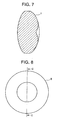
- a condenser lens 7 may be used which has, as shown in Figs. 6 and 7 , a normal convex surface on one lens surface and a convex surface with a recess portion provided at a central portion thereof on the other lens surface thereof.
- This condenser lens 7 may be disposed with either of the lens surfaces thereof directed towards the light source 5.
- a condenser lens 8 may be used which has, as shown in Figs. 8 and 9 , a flat surface on one lens surface and a convex surface with a recess portion provided at a central portion thereof on the other lens surface thereof.
- This condenser lens 8 may be disposed with either of the lens surfaces thereof directed towards the light source.
- the mirror tunnel 10 is a transparent prism and is provided along the optical axis K.
- This mirror tunnel 10 is made such that incident light from a light incident surface 10a is guided in the optical axis direction while totally reflected on an interface between sides of the mirror tunnel 10 and an outside air layer so as to be allowed to emerge from a light emerging surface 10b as a bundle of rays in which luminous intensity distribution is uniform.
- an angular tube in which a reflecting film is provided on the entirety of an inner circumferential surface thereof may be used as the mirror tunnel like this.
- the color wheel 9 is a circular rotary disc and includes color filters of red, blue and green which are arranged in a circumferential direction.
- the color wheel 9 is disposed with its rotating central axis X made to deviate to a side of the optical axis K.
- the lens 21 is such as to project light that emerges from the mirror tunnel 10 on to the micro mirror device 22.
- the lens 21 is illustrated as a single lens element, the lens 21 may be made up of a plurality of lens elements.
- the micro mirror device 22 is such as to form individual pixels for an image to be displayed by a plurality of micro mirrors and then change over light and shade of the pixels by changing over the inclination of the micro mirrors so as to project the image.
- the micro mirrors are formed of extremely thin metallic pieces such as aluminum pieces and have vertical and horizontal widths which range from 10 ⁇ m to 20 ⁇ m. These micro mirrors are provided, respectively, on a plurality ⁇ mirror drive elements (not shown) such as CMOS which are formed into a matrix-like arrangement in row and column directions.
- CMOS complementary metal-oxide-semiconductor
- the projection lens 23 is such as to enlarge and project reflected light from the micro mirror device 22 on to a screen (not shown).
- the projection lens 23 is illustrated as a single lens element, the projection lens 23 may be made up of a plurality of lens elements.
- a condenser lens 6 When a reflector is used which has a Korenick constant of -0.55106, a radius of curvature of 10.97669, a light emitting opening whose radius is 32.5mm and a lamp accommodation opening whose radius is 11mm, a condenser lens 6 will be used which has the following dimensions.
- Fig. 10 is a front view of a light source 5 side (hereinafter, appropriately referred to as a "side A") of the condenser lens 6.
- the radius of this lens surface is 8.3mm.
- an effective range X of the lens surface on the side A is within a range which is outside a range defined by a circle centered at the center point of the recess portion and having a radius of 1.5mm and inside a range defined by a circle centered at the center point of the recess portion and having a radius of 7.8mm+/-0.1mm.
- Fig. 11 is a front view of a mirror tunnel 10 side (hereinafter, appropriately referred to as a "side B") of the condenser lens 6. As shown in Fig.
- an effective range Y of the lens surface on the side B is a range which is outside a range defined by a circle centered at the center point of the recess portion and having a radius of 0. 8mm and inside a range defined by a circle centered at the center point of the recess portion and having a radius of 7.0mm.
- Fig. 12 shows a sectional view of the condenser lens 6, and in order to make clear the dimensions of the condenser lens 6 below, firstly, how to draw reference lines will be described using Fig. 12 .
- a reference line C which intersects with the optical axis K at right angles, is drawn in such a manner as to pass through the center of the recess portion on the lens surface on the side A of the condenser lens 6, and a reference line D is drawn in such a manner as to intersect with the optical axis K at right angles at a position 4mm apart from the reference line C along the optical axis K towards the side B.
- draw reference lines E, F respectively, from apex portions of convex portions on the lens surface on the side B of the condenser lens 6 to the reference line D in such a manner as to be parallel to the optical axis K.
- draw reference lines G, H respectively, also from apex portions of convex portions on the lens surface on the side A of the condenser lens 6 similarly in such a manner as to be parallel to the optical axis K.
- An arc L which has a radius equal to a distance from a point I where the reference line D intersects with the reference line E at right angles to an end portion J of a circumferential edge portion of the condenser lens 6 and which is centered at the point I, is formed from the end portion J towards the optical axis K.
- an arc O which has a radius equal to a distance from a point M where the reference line D intersects with the reference line F at right angles to an end portion N of a circumferential edge portion of the condenser lens 6 and which is centered at the point M, is formed from the end portion N towards the optical axis K. Then, a point where the arc L intersects with the arc O constitutes a central portion of the recess portion on the lens surface on the side A.
- an arc R which has a radius equal to a distance from a point P where the reference line C intersects with the reference line G at right angles to an end portion Q of a circumferential edge portion of the condenser lens 6 and which is centered at the point P, is formed from the end portion Q towards the optical axis K.
- an arc U which has a radius equal to a distance from a point S where the reference line C intersects with the reference line H at right angles to an end portion T of a circumferential edge portion of the condenser lens 6 and which is centered at the point S, is formed from the end portion T towards the optical axis K. Then, a point where the arc R intersects with the arc U constitutes a central portion of the recess portion on the lens surface on the side B.
- the distance of a line which connects the point I and the point M together is 7mm and the distance of a line which connects the point P and the point S together is 6mm.
- the radii of the arc L and the arc O are 5.5mm, respectively, and the radii of the arc R and the arc U are 6.4mm, respectively.
- Fig. 13 is a longitudinal sectional view of the light source unit 4 which illustrates positional relationships of the members which make up the light source unit 4. Note that in Fig. 13 , the illustration of the color wheel 9 is omitted in order to make clear the positional relationships.
- the ark 32 is disposed in such a manner as to lie on the optical axis K at a position 5. 6mm apart from a proximal portion of the reflector 24.
- the condenser lens 6 is disposed in such a manner that a point where a line which connects together the convex portions on the lens surface on the side A intersects with the optical axis K at right angles lies at a position 30. 5mm apart from the arc 32.
- the mirror tunnel 10 is disposed in such a manner that a distance from the arc 32 to a point where the light incident surface 10a intersects with the optical axis K equals to a distance of not more than 44.5mm.
- the bulb 30 of the light source 5 is disposed near the lamp accommodation opening 26 within the reflector 24 in such a manner that the focal point position of the radiated light radiated from the bulb 30 and reflected by the internal wall of the reflector 24 is formed further forward in the reflected light traveling direction than a distal end portion of the electrode introducing portion 31 which faces the condenser lens 6, most of the reflected light is made to illuminate portions of the condenser lens 6 other than the central portion thereof where the recess portion is provided so as to be gathered.
- the light which has been made to illuminate the condenser lens 6 so as to be gathered, is then made to illuminate the color wheel 9 so as to be converted into three colors of red, green and blue and thereafter is made to illuminate the light incident surface 10a of the mirror tunnel 10.
- the light that has emerged from the mirror tunnel 10 is made to illuminate the micro mirror device 22 after a bundle of rays thereof has been enlarged by the lens 21. Then, the light, which has been reflected by the micro mirror device 22, is then enlarged by the projection lens 23 so as to be projected on to a screen, not shown.
- the focal point position of the radiated light that is radiated from the bulb 30 and is reflected by the reflector 24 does not lie on the electrode introducing portion 31, there occurs no case where most of the radiated light impinges on the electrode introducing portion 31 of the lamp to thereby be dampened, and hence, the loss of the radiated light that illuminates the lens can be reduced, so that the utilization efficiency of radiated light that is radiated from the light source 5 can be enhanced, whereby the reflector 24 can be made smaller in size.
- the whole of the light source unit 4 can be made smaller in size than the related art light source unit.
- the light source unit 4 is made smaller in size in this way, the projector system 1 itself, which incorporates therein the light source unit 4, can be made smaller in size.
Landscapes
- Physics & Mathematics (AREA)
- Engineering & Computer Science (AREA)
- General Physics & Mathematics (AREA)
- Optics & Photonics (AREA)
- General Engineering & Computer Science (AREA)
- Multimedia (AREA)
- Signal Processing (AREA)
- Projection Apparatus (AREA)
- Non-Portable Lighting Devices Or Systems Thereof (AREA)
Applications Claiming Priority (2)
| Application Number | Priority Date | Filing Date | Title |
|---|---|---|---|
| JP2004361534A JP3912407B2 (ja) | 2004-12-14 | 2004-12-14 | 光源ユニット及びプロジェクタ装置 |
| PCT/JP2005/021310 WO2006064632A1 (en) | 2004-12-14 | 2005-11-15 | Light source unit and projector system |
Publications (2)
| Publication Number | Publication Date |
|---|---|
| EP1716363A1 EP1716363A1 (en) | 2006-11-02 |
| EP1716363B1 true EP1716363B1 (en) | 2009-04-15 |
Family
ID=35759403
Family Applications (1)
| Application Number | Title | Priority Date | Filing Date |
|---|---|---|---|
| EP05804079A Ceased EP1716363B1 (en) | 2004-12-14 | 2005-11-15 | Light source unit and projector system |
Country Status (8)
| Country | Link |
|---|---|
| US (1) | US7607787B2 (https=) |
| EP (1) | EP1716363B1 (https=) |
| JP (1) | JP3912407B2 (https=) |
| KR (1) | KR20060118586A (https=) |
| CN (1) | CN100567802C (https=) |
| DE (1) | DE602005013918D1 (https=) |
| TW (1) | TWI296068B (https=) |
| WO (1) | WO2006064632A1 (https=) |
Families Citing this family (4)
| Publication number | Priority date | Publication date | Assignee | Title |
|---|---|---|---|---|
| JP4218649B2 (ja) * | 2005-03-07 | 2009-02-04 | カシオ計算機株式会社 | 光源ユニット及びプロジェクタ装置 |
| WO2007081809A2 (en) * | 2006-01-11 | 2007-07-19 | Philip Premysler | Illumination optics |
| DE102006049600A1 (de) * | 2006-10-20 | 2008-04-24 | Patent-Treuhand-Gesellschaft für elektrische Glühlampen mbH | Lampenmodul für Projektoren |
| AT507529B1 (de) * | 2008-11-04 | 2016-05-15 | Günther Conzatti | Beleuchtungseinrichtung mit reduzierter blendwirkung |
Family Cites Families (30)
| Publication number | Priority date | Publication date | Assignee | Title |
|---|---|---|---|---|
| US1064010A (en) * | 1909-02-11 | 1913-06-10 | Entpr Optical Mfg Company | Optical projecting apparatus. |
| US1085795A (en) * | 1912-10-11 | 1914-02-03 | Boylite Concentrator Inc | Projection instrument. |
| US3732417A (en) * | 1971-06-16 | 1973-05-08 | Grimes Manuf Co | Square lite projector using prismatic lens |
| US4355350A (en) | 1980-09-02 | 1982-10-19 | Polaroid Corporation | Reflector for use in an artificial lighting device |
| DE3228531A1 (de) * | 1982-07-30 | 1984-02-02 | Patent-Treuhand-Gesellschaft für elektrische Glühlampen mbH, 8000 München | Beleuchtungssystem, bestehend aus halogen-ellipsoidreflektorlampe mit der lampe nachgeordneter linse und einem waermeabsorptionsfilter |
| US4642740A (en) | 1984-10-22 | 1987-02-10 | General Electric Company | Constant magnification light collection system |
| EP0198676A3 (en) * | 1985-04-12 | 1988-10-12 | Oscar Moreno Gil | Bicurve lenses |
| ES8604355A1 (es) | 1985-04-12 | 1986-02-01 | Moreno Gil Oscar | Lentes bicurvoconicas |
| JPH04104241A (ja) | 1990-08-24 | 1992-04-06 | Seiko Epson Corp | 照明光源装置 |
| JP2973750B2 (ja) * | 1992-03-31 | 1999-11-08 | 松下電器産業株式会社 | 照明光学装置とそれを用いた投写型表示装置 |
| JPH0651401A (ja) | 1992-07-27 | 1994-02-25 | Fujitsu General Ltd | プロジェクタの光源装置 |
| JP3508190B2 (ja) | 1993-12-21 | 2004-03-22 | セイコーエプソン株式会社 | 照明装置及び投写型表示装置 |
| FR2733062B1 (fr) * | 1995-04-13 | 1997-06-27 | Thomson Multimedia Sa | Systeme de projection comportant un reflecteur et une lentille de champ a surface libre |
| JPH10288757A (ja) | 1997-02-13 | 1998-10-27 | Canon Inc | 照明装置及び投影装置 |
| KR100219638B1 (ko) * | 1997-05-27 | 1999-09-01 | 윤종용 | 반사형 프로젝트 장치 |
| JP3823659B2 (ja) * | 2000-02-04 | 2006-09-20 | セイコーエプソン株式会社 | プロジェクタ |
| DE10063134A1 (de) * | 2000-12-18 | 2002-06-27 | Weigert Dedo Film Gmbh | Fokussierbarer Scheinwerfer mit Negativlinse |
| JP2002214563A (ja) * | 2001-01-12 | 2002-07-31 | Mitsubishi Electric Corp | ランプ、偏光変換光学系、集光光学系および画像表示装置 |
| JP4722312B2 (ja) * | 2001-03-30 | 2011-07-13 | 三菱電機株式会社 | ランプ、集光光学系および画像表示装置 |
| JP2002350778A (ja) | 2001-05-24 | 2002-12-04 | Seiko Epson Corp | 照明光学系及びこれを備えたプロジェクタ |
| US7001027B2 (en) * | 2003-03-25 | 2006-02-21 | Seiko Epson Corporation | Light source device and projector |
| US7068446B2 (en) * | 2003-05-05 | 2006-06-27 | Illumitech Inc. | Compact non-imaging light collector |
| US7075713B2 (en) * | 2003-05-05 | 2006-07-11 | University Of Central Florida Research Foundation | High efficiency collector for laser plasma EUV source |
| WO2005008329A1 (ja) | 2003-07-16 | 2005-01-27 | Matsushita Electric Industrial Co., Ltd. | 光源装置、照明装置、および投写型表示装置 |
| US7178922B2 (en) * | 2003-10-03 | 2007-02-20 | Mitsubishi Denki Kabushiki Kaisha | Lamp, condensing optical system, and image display device |
| US7164470B2 (en) * | 2003-10-14 | 2007-01-16 | Bausch & Lomb Incorporated | Depth of field enhancement for optical comparator |
| JP4063213B2 (ja) * | 2003-12-09 | 2008-03-19 | カシオ計算機株式会社 | 光源装置及びそれを備えたプロジェクタ |
| WO2006014765A1 (en) * | 2004-07-27 | 2006-02-09 | Whiterock Design, Llc | Illumination system |
| JP4218649B2 (ja) * | 2005-03-07 | 2009-02-04 | カシオ計算機株式会社 | 光源ユニット及びプロジェクタ装置 |
| JP4892938B2 (ja) * | 2005-11-18 | 2012-03-07 | カシオ計算機株式会社 | 光源ユニット及びプロジェクタ装置 |
-
2004
- 2004-12-14 JP JP2004361534A patent/JP3912407B2/ja not_active Expired - Fee Related
-
2005
- 2005-11-15 WO PCT/JP2005/021310 patent/WO2006064632A1/en not_active Ceased
- 2005-11-15 KR KR1020067016348A patent/KR20060118586A/ko not_active Ceased
- 2005-11-15 CN CNB2005800049360A patent/CN100567802C/zh not_active Expired - Fee Related
- 2005-11-15 DE DE602005013918T patent/DE602005013918D1/de not_active Expired - Lifetime
- 2005-11-15 EP EP05804079A patent/EP1716363B1/en not_active Ceased
- 2005-12-01 US US11/293,476 patent/US7607787B2/en active Active
- 2005-12-09 TW TW094143513A patent/TWI296068B/zh not_active IP Right Cessation
Also Published As
| Publication number | Publication date |
|---|---|
| JP2006171210A (ja) | 2006-06-29 |
| WO2006064632A1 (en) | 2006-06-22 |
| JP3912407B2 (ja) | 2007-05-09 |
| HK1097310A1 (zh) | 2007-06-22 |
| TWI296068B (en) | 2008-04-21 |
| US20060126341A1 (en) | 2006-06-15 |
| US7607787B2 (en) | 2009-10-27 |
| CN100567802C (zh) | 2009-12-09 |
| CN1918426A (zh) | 2007-02-21 |
| TW200628960A (en) | 2006-08-16 |
| EP1716363A1 (en) | 2006-11-02 |
| DE602005013918D1 (de) | 2009-05-28 |
| KR20060118586A (ko) | 2006-11-23 |
Similar Documents
| Publication | Publication Date | Title |
|---|---|---|
| US5491525A (en) | Illumination unit for liquid crystal projection display apparatus and liquid crystal display apparatus having it used | |
| JP2004326129A (ja) | 照明装置および投写型表示装置 | |
| JP2001337394A (ja) | 照明光学装置および投写型表示装置 | |
| EP1716363B1 (en) | Light source unit and projector system | |
| US7252410B2 (en) | Projector | |
| JP2005156881A (ja) | 光源装置及びプロジェクタ | |
| CN115755509A (zh) | 激光光源及激光投影装置 | |
| JP4218649B2 (ja) | 光源ユニット及びプロジェクタ装置 | |
| US7524088B2 (en) | Light source unit and projector system | |
| JP2006058488A (ja) | 照明光学装置およびこれを用いた投影型表示装置 | |
| JP2001066697A (ja) | 投射型表示装置用光源および液晶投射型表示装置 | |
| JP3228626B2 (ja) | 投射型表示装置 | |
| HK1097310B (en) | Light source unit and projector system | |
| JP2007140344A (ja) | 照明光学系および画像投影装置 | |
| JP2001083435A (ja) | ライトガイド照明装置 | |
| HK1123345B (en) | Light source unit and projector system | |
| JPH07175017A (ja) | 液晶プロジェクタ | |
| JP2006258895A (ja) | 光源ユニット及びプロジェクター |
Legal Events
| Date | Code | Title | Description |
|---|---|---|---|
| PUAI | Public reference made under article 153(3) epc to a published international application that has entered the european phase |
Free format text: ORIGINAL CODE: 0009012 |
|
| 17P | Request for examination filed |
Effective date: 20060726 |
|
| AK | Designated contracting states |
Kind code of ref document: A1 Designated state(s): AT BE BG CH CY CZ DE DK EE ES FI FR GB GR HU IE IS IT LI LT LU LV MC NL PL PT RO SE SI SK TR |
|
| AX | Request for extension of the european patent |
Extension state: AL BA HR MK YU |
|
| 17Q | First examination report despatched |
Effective date: 20070704 |
|
| DAX | Request for extension of the european patent (deleted) | ||
| RBV | Designated contracting states (corrected) |
Designated state(s): DE FR GB |
|
| GRAP | Despatch of communication of intention to grant a patent |
Free format text: ORIGINAL CODE: EPIDOSNIGR1 |
|
| GRAS | Grant fee paid |
Free format text: ORIGINAL CODE: EPIDOSNIGR3 |
|
| GRAA | (expected) grant |
Free format text: ORIGINAL CODE: 0009210 |
|
| AK | Designated contracting states |
Kind code of ref document: B1 Designated state(s): DE FR GB |
|
| REG | Reference to a national code |
Ref country code: GB Ref legal event code: FG4D |
|
| REF | Corresponds to: |
Ref document number: 602005013918 Country of ref document: DE Date of ref document: 20090528 Kind code of ref document: P |
|
| PLBE | No opposition filed within time limit |
Free format text: ORIGINAL CODE: 0009261 |
|
| STAA | Information on the status of an ep patent application or granted ep patent |
Free format text: STATUS: NO OPPOSITION FILED WITHIN TIME LIMIT |
|
| 26N | No opposition filed |
Effective date: 20100118 |
|
| REG | Reference to a national code |
Ref country code: FR Ref legal event code: PLFP Year of fee payment: 11 |
|
| REG | Reference to a national code |
Ref country code: FR Ref legal event code: PLFP Year of fee payment: 12 |
|
| REG | Reference to a national code |
Ref country code: FR Ref legal event code: PLFP Year of fee payment: 13 |
|
| REG | Reference to a national code |
Ref country code: FR Ref legal event code: PLFP Year of fee payment: 14 |
|
| PGFP | Annual fee paid to national office [announced via postgrant information from national office to epo] |
Ref country code: DE Payment date: 20181030 Year of fee payment: 14 |
|
| PGFP | Annual fee paid to national office [announced via postgrant information from national office to epo] |
Ref country code: GB Payment date: 20181114 Year of fee payment: 14 Ref country code: FR Payment date: 20181011 Year of fee payment: 14 |
|
| REG | Reference to a national code |
Ref country code: DE Ref legal event code: R119 Ref document number: 602005013918 Country of ref document: DE |
|
| GBPC | Gb: european patent ceased through non-payment of renewal fee |
Effective date: 20191115 |
|
| PG25 | Lapsed in a contracting state [announced via postgrant information from national office to epo] |
Ref country code: FR Free format text: LAPSE BECAUSE OF NON-PAYMENT OF DUE FEES Effective date: 20191130 Ref country code: GB Free format text: LAPSE BECAUSE OF NON-PAYMENT OF DUE FEES Effective date: 20191115 Ref country code: DE Free format text: LAPSE BECAUSE OF NON-PAYMENT OF DUE FEES Effective date: 20200603 |