EP1716331B1 - Procede de synchronisation des cylindres en termes de quantites d'injection de carburant dans un moteur thermique - Google Patents
Procede de synchronisation des cylindres en termes de quantites d'injection de carburant dans un moteur thermique Download PDFInfo
- Publication number
- EP1716331B1 EP1716331B1 EP05707907A EP05707907A EP1716331B1 EP 1716331 B1 EP1716331 B1 EP 1716331B1 EP 05707907 A EP05707907 A EP 05707907A EP 05707907 A EP05707907 A EP 05707907A EP 1716331 B1 EP1716331 B1 EP 1716331B1
- Authority
- EP
- European Patent Office
- Prior art keywords
- injection
- adaptation
- operating point
- parameter
- values
- Prior art date
- Legal status (The legal status is an assumption and is not a legal conclusion. Google has not performed a legal analysis and makes no representation as to the accuracy of the status listed.)
- Expired - Fee Related
Links
Images

Classifications
-
- F—MECHANICAL ENGINEERING; LIGHTING; HEATING; WEAPONS; BLASTING
- F02—COMBUSTION ENGINES; HOT-GAS OR COMBUSTION-PRODUCT ENGINE PLANTS
- F02D—CONTROLLING COMBUSTION ENGINES
- F02D41/00—Electrical control of supply of combustible mixture or its constituents
- F02D41/22—Safety or indicating devices for abnormal conditions
- F02D41/221—Safety or indicating devices for abnormal conditions relating to the failure of actuators or electrically driven elements
-
- F—MECHANICAL ENGINEERING; LIGHTING; HEATING; WEAPONS; BLASTING
- F02—COMBUSTION ENGINES; HOT-GAS OR COMBUSTION-PRODUCT ENGINE PLANTS
- F02D—CONTROLLING COMBUSTION ENGINES
- F02D41/00—Electrical control of supply of combustible mixture or its constituents
- F02D41/02—Circuit arrangements for generating control signals
- F02D41/14—Introducing closed-loop corrections
- F02D41/1401—Introducing closed-loop corrections characterised by the control or regulation method
- F02D41/1402—Adaptive control
-
- F—MECHANICAL ENGINEERING; LIGHTING; HEATING; WEAPONS; BLASTING
- F02—COMBUSTION ENGINES; HOT-GAS OR COMBUSTION-PRODUCT ENGINE PLANTS
- F02D—CONTROLLING COMBUSTION ENGINES
- F02D41/00—Electrical control of supply of combustible mixture or its constituents
- F02D41/02—Circuit arrangements for generating control signals
- F02D41/14—Introducing closed-loop corrections
- F02D41/1497—With detection of the mechanical response of the engine
- F02D41/1498—With detection of the mechanical response of the engine measuring engine roughness
Definitions
- the invention relates to a method for equalizing the differences in the injection quantity between the cylinders of an internal combustion engine, in which the injection quantity differences, which are present at an operating point in the lower speed range at the applicable there in regular driving injection parameter values by means of a cylinder-specific measurement method for detecting the rough running of the internal combustion engine determined and assigned to the low operating point, and in which for operating areas with higher loads and speeds for a selected injection parameter, an adaptation of the injection quantity differences is performed.
- the injection quantity differences determined at a low operating point can not be used for equality in the entire operating range, eg. B. can be used as the global correction factors for a control parameter of the injectors, but must be adapted to the applicable at higher operating points injection parameters, but this is not readily possible because of the mentioned condition of steady-state operating conditions for the smooth running control.
- the invention is based on the object to provide a method of the type mentioned, which allows to determine the actual, injection-parameter-dependent systematic error with respect to the injection quantities with respect to a cylinder equalization in a simple manner.
- the selected injection parameter is set for adaptation to a value which deviates from the value applicable there in normal driving operation.
- the regular driving operation it is understood that e.g. at low loads corresponding low injection pressures.
- the regular driving operation is deviated, if e.g. at low loads high injection pressures.
- the injection quantity differences can be determined by means of the measurement of the rough running and learned as adaptation values assigned to the respective injection parameter value.
- At least one second injection parameter is set such that the operating point remains at least approximately stationary in order to limit the dynamics of the low operating point during the adaptation.
- This can advantageously be achieved by adapting to successively higher values of the injection parameter selected injection pressure to limit the dynamics of the low operating point in each case a correspondingly shorter injection period is set.
- the second or further injection parameters are thus controlled here as auxiliary quantities such that the driver does not notice anything of the adaptation process. Since a few piston strokes are sufficient for adaptation, the engine control can easily be adjusted so that the driver can not cancel the stationary conditions during the critical adaptation phase, or only when exceeding a threshold in the desired performance requested by the driver via the gas.
- a low operating point can be selected for the adaptation, in which the highest sensitivity and / or reliability of the measurement of rough running is achieved, although a correct adaptation for high operating ranges is made.
- the low operating point in the idling range can be selected.
- the learned adaptation values are used to calculate cylinder-specific correction factors with which, as a rule in the context of the smooth running control during the adaptation process and while driving, a control parameter of an injection device of the internal combustion engine is applied such that an equalization of the injection quantities takes place.
- the injection device for each cylinder is formed by an injector with a piezoelectric actuator, wherein the drive energy of the actuators is used as a driving parameter. It can therefore in particular for different values of the injection pressure an adaptation of the actuator stroke necessary for equality is carried out.
- the rotational acceleration of the crankshaft of the internal combustion engine caused by the cylinder-specific different injection quantities can be evaluated.
- the determination of the adapted injection quantity differences or the adapted correction factors for equality can thus be based on a very accurate measurement methodology.
- the inventive method also opens up the possibility that the absolute value of the associated injection quantity is determined at the stationary operating point set for adaptation with equivalent injection quantities from a stored torque model of the internal combustion engine.
- a diagnosis of the absolute value of the injection quantity is just for the diagnosis of small injection quantities, in particular of pre-injection amounts that are in the range of a few milligrams, crucial for compliance with the limits of exhaust emissions.
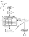
- an initialization phase 2 is provided in the next step, in which the adaptation values stored in an earlier diagnostic cycle are loaded into an engine control unit (not shown).
- the initialization of a new diagnostic cycle can be done both after each startup of the internal combustion engine, as well as after certain, specifiable time or maintenance intervals.
- the activation conditions are checked in a passive diagnostic step 3.
- the aim is to wait until the preferred operating conditions for adaptation to a regular or deviating injection parameter value have been reached. These include, for example, the load, the speed or the coolant temperature. If necessary, the motor control must be changed so that in the subsequent adaptation, the dynamics of the temporal change of the selected for performing the adaptation cycle operating point is limited.
- the actual, active diagnostic cycle 4 is started.
- the regular injection parameters 5 associated with the engine operating state see injection parameter set in FIG. 1
- a rough running control 6 is performed.
- the injection quantities of the individual injectors of the internal combustion engine are matched to one another in the preferred, low operating point.
- an injection quantity known from the torque model is concluded, which must be given in accordance with the achieved torque.
- step 7 adaptive of the activation parameters
- further injection parameters or injection parameter sets i are loaded and the uneven-running control is carried out with a determination of the injection quantity differences present at the set value of the selected injection parameter or with the equality by corresponding correction factors for a control parameter.
- a suitable drive parameter such as, for example, the energy supplied to the actuators
- the resulting adaptation values are added to the injection parameter set, ie primarily the injection parameters, such as the injection parameters.
- Injection pressure and injection period whose influence on the injection quantity differences to be recorded, assigned and stored so that they can be retrieved later, when driving with higher loads and speeds and the associated regular values of the selected injection parameter for direct injection amount equalization without diagnostic cycle.
- a sufficient number of interpolation points typically five to ten
- the different injection quantities of injectors which depend on the injection duration, can be easily adjusted to one another in such a way that the stroke of the actuators is changed.
- the injector control variable Of course, the drive energy used can also be used to vary the start of injection.
- step 11 The illustrated method performs an initialization in step 11.
- the stored adaptation values are loaded.
- step 12 it is checked whether the activation conditions are fulfilled. This means to understand whether constant operating conditions are present, such as constant load, constant speed, constant temperature of the coolant, etc.
- the diagnosis remains passive until the activation conditions are met in step 12.
- step 14 continue by loading the injection parameters for an initial charge / discharge time.
- the initial charge / discharge time can be set to 200 ⁇ s.
- the injection parameters include the injection pressure, injector energy, type of injection, which means whether it is a pre-, main-, post-injection. Once these parameters have been loaded, the procedure is continued in step 15.
- the running disturbance regulation takes place cylinder-selectively, ie that for example for a four-cylinder engine first the cylinder Nr.1 is regulated. If the injection parameters for the injector of cylinder No. 1 are set, the injector of the second cylinder follows.
- the regulation may include the charge / discharge time, the injection pressure, the drive energy, and set the type of injection.
- the control can be performed at a defined (fixed) control duration (injection period) and defined (fixed) injection pressure, wherein the actuator energy is adjusted accordingly. With a rail pressure of, for example, 1500 bar and an injection quantity of 0.84 mg, activation times of less than 160 ⁇ s must be realized.
- step 16 it is checked whether with these variables the rough running is below a threshold value S. If this is not the case, then in step 17, the activation duration must also be changed. This is particularly necessary for "bad" manufactured injectors that poor or not cope with these short load / unload times. In such injectors and short discharge times, the amount of fuel injected is independent of the actuator energy. It sets up a kind of "quantity saturation” and the injection quantity can not be changed by increasing the actuator energy. This means that an injection adaptation in a defined operating state does not have to be carried out solely by energy adaptation, but by means of an extension of the activation duration, which thus extends the injection duration.
- step 18 it is checked whether the charge / discharge time ⁇ i is greater than or equal to an extreme value.
- the extreme value is for example 140 ⁇ s.
- the initial value ⁇ 0 is 200 ⁇ s.
- the index i here is equal to zero. Since the condition established in step 19 is not satisfied, it continues in step 20. Before loading the next parameter set in step 14, the loading / unloading time is previously reduced by 10 ⁇ s in step 20. Thus, the charge / discharge time ⁇ 1 is equal to 190 ⁇ s.
- step 21 only the index is incremented by one.
- the existing injection parameters for ⁇ 1 are now loaded in step 14.
- the constant injection pressure eg 1500 bar
- the actuator energy is determined according to steps 14 to 19 for each charge / discharge time of 200 to 140 ⁇ s. This can be done for different pressures.
- the method ends in step 22.
- the step-by-step change of the charging / discharging time by 10 ⁇ s in step 20 has been given by way of example only. For a finer modeling, differences from one charge / discharge time to the next charge / discharge time of 1 ⁇ s are conceivable. This diagnosis according to the invention can be carried out very quickly, since only a few piston strokes are sufficient.
- the method according to the invention makes it possible to diagnose the injection quantity differences or the injection quantity itself at a preferred, low operating point at which the highest sensitivity and reliability of the rough-running control exists.
- the diagnosis and adaptation then also take place for injection parameter values which apply to other operating points during driving operation. It is done at the low operating point so both a compensation of the injection quantity differences between the individual injectors as well as a calibration of the injection quantity to the associated, in the diagnostic cycle artificially set values of the selected injection parameter, wherein an undesirable movement of the adaptation operating point by the opposite setting of other injection parameter values is prevented or limited.
- an injection quantity equalization by energy control of the injector drive parameter is dependent on, in particular, the injection parameter pressure.
Claims (13)
- Procédé de compensation des différences de débit d'injection entre les cylindres d'un moteur à combustion interne, dans lequel les différences de débit d'injection présentées à un point de fonctionnement de la plage de régime de rotation basse avec les valeurs de paramètres d'injection qui sont valides en condition normale de roulage, sont déterminées au moyen d'une méthode de mesure spécifique à chaque cylindre pour la saisie de l'instabilité de marche du moteur à combustion interne, et associées au point de fonctionnement bas, et dans lequel, pour des plages de fonctionnement à charge et à régime de rotation élevés pour un paramètre d'injection sélectionné, il est procédé à une adaptation des différences de débit d'injection,
caractérisé
en ce qu'au point de fonctionnement bas, le paramètre d'injection sélectionné pour l'adaptation (4, 5, 6, 7) est réglé à une valeur autre que la valeur qui est valide en condition normale de roulage, et en ce que pour la valeur réglée, les différences de débit d'injection sont respectivement déterminées au moyen de la mesure de l'instabilité de marche et apprises comme valeurs d'adaptation associées à la valeur de paramètre d'injection correspondante, la dynamique du point de fonctionnement variant avec la valeur de paramètre d'injection respectivement réglée étant limitée en cours d'adaptation (4, 5, 6, 7). - Procédé selon la revendication 1,
caractérisé en ce que, pour la limitation de la dynamique du point de fonctionnement bas en cours d'adaptation (4, 5, 6, 7), au moins un deuxième paramètre d'injection est réglé de telle manière que le point de fonctionnement reste au moins approximativement fixe. - Procédé selon la revendication 2,
caractérisé en ce que, pour l'adaptation (4, 5, 6, 7) à des valeurs consécutives supérieures de la pression d'injection sélectionnée comme paramètre d'injection, une durée d'injection inférieure en conséquence est réglée pour la limitation de la dynamique du point de fonctionnement bas. - Procédé selon la revendication 2,
caractérisé en ce que pour l'adaptation (4, 5, 6, 7) à des valeurs consécutives inférieures de la pression d'injection sélectionnée comme paramètre d'injection, une durée d'injection supérieure en conséquence est réglée pour la limitation de la dynamique du point de fonctionnement bas. - Procédé selon l'une des revendications 2 ou 3,
caractérisé en ce que la pression d'injection est graduellement variée d'une valeur déterminée. - Procédé selon l'une des revendications précédentes,
caractérisé en ce que, pour l'adaptation (4, 5, 6, 7), un point de fonctionnement inférieur est sélectionné, dans lequel sont obtenues la sensibilité et/ou la fiabilité maximales de la mesure de l'instabilité de marche. - Procédé selon l'une des revendications précédentes,
caractérisé en ce que le point de fonctionnement bas est sélectionné dans la plage de régime au ralenti. - Procédé selon l'une des revendications précédentes,
caractérisé en ce que les valeurs d'adaptation apprises servent au calcul de facteurs de correction spécifiques à chaque cylindre, au moyen desquels un paramètre de commande d'un système d'injection du moteur à combustion interne est appliqué de manière à obtenir une équivalence des débits d'injection. - Procédé selon la revendication 8,
caractérisé en ce que le système d'injection pour chaque cylindre est formé par un injecteur à actionneur piézoélectrique, l'énergie d'excitation des actionneurs étant utilisée comme paramètre de commande. - Procédé selon la revendication 9,
caractérisé en ce que pour un temps de chargement/déchargement défini de l'injecteur, l'énergie d'actionneur est ajustée en conséquence. - Procédé selon la revendication 10,
caractérisé en ce que le temps de chargement/déchargement de l'injection principale est synchronisé avec une valeur initiale (τ0) et graduellement varié jusqu'à une valeur extrême, l'énergie d'actionneur étant ajustée en conséquence à chaque étape. - Procédé selon l'une des revendications précédentes,
caractérisé en ce que, pour la saisie de l'instabilité de marche du moteur à combustion interne, l'accélération de la rotation du vilebrequin du moteur à combustion interne causée par les différents débits d'injection spécifiques à chaque cylindre est évaluée. - Procédé selon la revendication 12,
caractérisé en ce qu'au point de fonctionnement fixe réglé pour l'adaptation (4, 5, 6, 7) avec des débits d'injection équivalents, la valeur absolue du débit d'injection correspondant est déterminée à partir d'un modèle mémorisé de couple du moteur à combustion interne.
Applications Claiming Priority (2)
| Application Number | Priority Date | Filing Date | Title |
|---|---|---|---|
| DE102004006554A DE102004006554B3 (de) | 2004-02-10 | 2004-02-10 | Verfahren zur Zylindergleichstellung bezüglich der Kraftstoff-Einspritzmengen bei einer Brennkraftmaschine |
| PCT/EP2005/050428 WO2005078263A1 (fr) | 2004-02-10 | 2005-02-01 | Procede de synchronisation des cylindres en termes de quantites d'injection de carburant dans un moteur thermique |
Publications (2)
| Publication Number | Publication Date |
|---|---|
| EP1716331A1 EP1716331A1 (fr) | 2006-11-02 |
| EP1716331B1 true EP1716331B1 (fr) | 2008-08-20 |
Family
ID=34625821
Family Applications (1)
| Application Number | Title | Priority Date | Filing Date |
|---|---|---|---|
| EP05707907A Expired - Fee Related EP1716331B1 (fr) | 2004-02-10 | 2005-02-01 | Procede de synchronisation des cylindres en termes de quantites d'injection de carburant dans un moteur thermique |
Country Status (4)
| Country | Link |
|---|---|
| US (1) | US7392789B2 (fr) |
| EP (1) | EP1716331B1 (fr) |
| DE (2) | DE102004006554B3 (fr) |
| WO (1) | WO2005078263A1 (fr) |
Families Citing this family (13)
| Publication number | Priority date | Publication date | Assignee | Title |
|---|---|---|---|---|
| EP1760873B8 (fr) * | 2005-09-06 | 2008-06-18 | Siemens Aktiengesellschaft | Procédé et dispositif de commande d'un actionneur piézoélectrique |
| JP4487922B2 (ja) * | 2005-12-15 | 2010-06-23 | 株式会社デンソー | 燃料噴射装置の初期設定方法、および燃料噴射装置の初期設定方法に用いられる初期設定装置 |
| DE102006012656A1 (de) * | 2006-03-20 | 2007-09-27 | Siemens Ag | Verfahren und Vorrichtung zum Betreiben einer Brennkraftmaschine |
| DE102006036568A1 (de) * | 2006-08-04 | 2008-02-07 | Siemens Ag | Verfahren zur Detektion von Ventilöffnungszeitpunkten von Kraftstoffeinspritzsystemen einer Brennkraftmaschine |
| JP4532532B2 (ja) * | 2007-08-30 | 2010-08-25 | 株式会社デンソー | 燃料噴射制御装置及び燃料噴射システム |
| JP4407730B2 (ja) * | 2007-08-31 | 2010-02-03 | 株式会社デンソー | 内燃機関の燃料噴射制御装置 |
| DE102007044937B4 (de) | 2007-09-20 | 2010-03-25 | Continental Automotive Gmbh | Verfahren und Vorrichtung zum Betreiben einer Brennkraftmaschine |
| DE102007053406B3 (de) | 2007-11-09 | 2009-06-04 | Continental Automotive Gmbh | Verfahren und Vorrichtung zur Durchführung sowohl einer Adaption wie einer Diagnose bei emissionsrelevanten Steuereinrichtungen in einem Fahrzeug |
| DE102008006674B4 (de) * | 2008-01-30 | 2020-08-27 | Bayerische Motoren Werke Aktiengesellschaft | Verfahren zum Betreiben einer Brennkraftmaschine mit Benzin-Direkteinspritzung |
| DE102008001081B4 (de) * | 2008-04-09 | 2021-11-04 | Robert Bosch Gmbh | Verfahren und Motorsteuergerät zum Steuern eines Verbrennungsmotors |
| WO2011072293A2 (fr) * | 2009-12-11 | 2011-06-16 | Purdue Research Foundation | Estimation de débit pour l'injection piézoélectrique de carburant |
| DE102010014320B4 (de) * | 2010-04-09 | 2016-10-27 | Continental Automotive Gmbh | Verfahren zum Anpassen der tatsächlichen Einspritzmenge, Einspritzvorrichtung und Brennkraftmaschine |
| JP6350226B2 (ja) | 2014-11-05 | 2018-07-04 | 株式会社デンソー | 内燃機関の燃料噴射制御装置 |
Family Cites Families (10)
| Publication number | Priority date | Publication date | Assignee | Title |
|---|---|---|---|---|
| DE3336028C3 (de) * | 1983-10-04 | 1997-04-03 | Bosch Gmbh Robert | Einrichtung zur Beeinflussung von Steuergrößen einer Brennkraftmaschine |
| JPH0650077B2 (ja) * | 1984-08-10 | 1994-06-29 | 日本電装株式会社 | 内燃機関用燃料噴射量制御方法 |
| US5385129A (en) * | 1991-07-04 | 1995-01-31 | Robert Bosch Gmbh | System and method for equalizing fuel-injection quantities among cylinders of an internal combustion engine |
| DE19700711C2 (de) * | 1997-01-10 | 1999-05-12 | Siemens Ag | Verfahren zum Ausgleich des systematischen Fehlers an Einspritzvorrichtungen für eine Brennkraftmaschine |
| DE19720009C2 (de) * | 1997-05-13 | 2000-08-31 | Siemens Ag | Verfahren zur Zylindergleichstellung bezüglich der Kraftstoff-Einspritzmenge bei einer Brennkraftmaschine |
| US5809969A (en) * | 1997-07-29 | 1998-09-22 | Chrysler Corporation | Method for processing crankshaft speed fluctuations for control applications |
| DE19741965C1 (de) * | 1997-09-23 | 1999-01-21 | Siemens Ag | Verfahren zur Laufruheregelung |
| DE19855939A1 (de) | 1997-12-18 | 1999-06-24 | Fev Motorentech Gmbh & Co Kg | Verfahren zum Betrieb einer Mehrzylinder-Kolbenbrennkraftmaschine mit Kraftstoffeinspritzung |
| DE10012025A1 (de) | 2000-03-11 | 2001-10-18 | Bosch Gmbh Robert | Verfahren zum Betreiben einer mehrzylindrigen Brennkraftmaschine |
| JP2001349243A (ja) * | 2000-06-07 | 2001-12-21 | Isuzu Motors Ltd | エンジンの燃料噴射制御装置 |
-
2004
- 2004-02-10 DE DE102004006554A patent/DE102004006554B3/de not_active Expired - Fee Related
-
2005
- 2005-02-01 DE DE502005005103T patent/DE502005005103D1/de active Active
- 2005-02-01 EP EP05707907A patent/EP1716331B1/fr not_active Expired - Fee Related
- 2005-02-01 US US10/597,846 patent/US7392789B2/en active Active
- 2005-02-01 WO PCT/EP2005/050428 patent/WO2005078263A1/fr active IP Right Grant
Also Published As
| Publication number | Publication date |
|---|---|
| DE502005005103D1 (de) | 2008-10-02 |
| EP1716331A1 (fr) | 2006-11-02 |
| US7392789B2 (en) | 2008-07-01 |
| WO2005078263A1 (fr) | 2005-08-25 |
| US20070163543A1 (en) | 2007-07-19 |
| DE102004006554B3 (de) | 2005-06-30 |
Similar Documents
| Publication | Publication Date | Title |
|---|---|---|
| EP1716331B1 (fr) | Procede de synchronisation des cylindres en termes de quantites d'injection de carburant dans un moteur thermique | |
| EP1716330B1 (fr) | Procede de compensation d'ecarts de quantites d'injection entre les cylindres d'un moteur a combustion interne | |
| DE102007028900B4 (de) | Verfahren und Vorrichtung zur Diagnose eines mit einer Kraftstoffverteilerleiste in Verbindung stehenden Einspritzventils einer Brennkraftmaschine | |
| DE102008040626A1 (de) | Verfahren zur Bestimmung der eingespritzten Kraftstoffmasse einer Einzeleinspritzung und Vorrichtung zur Durchführung des Verfahrens | |
| DE102007048650A1 (de) | Verfahren und Vorrichtung zur Optimierung der Verbrennung von Dieselkraftstoffen mit unterschiedlichen Cetanzahlen in einer Diesel-Brennkraftmaschine | |
| WO2008110346A2 (fr) | Procédé de régulation d'une injection d'un injecteur d'un moteur à combustion interne à injection directe et moteur à combustion interne à injection directe | |
| DE102005014920A1 (de) | Verfahren zur zylinderindividuellen Einstellung von Einspritzzeiten einer Verbrennungskraftmaschine | |
| DE102015214780A1 (de) | Verfahren zur Erkennung fehlerhafter Komponenten eines Kraftstoffeinspritzsystems | |
| DE102008002482A1 (de) | Verfahren und Vorrichtung zur Kalibrierung eines Kraftstoffzumesssystems einer Brennkraftmaschine insbesondere eines Kraftfahrzeugs | |
| WO2020030351A1 (fr) | Procédé et dispositif pour faire fonctionner un moteur à combustion comprenant un système d'injection à rampe commune | |
| DE102008042933B4 (de) | Verfahren und Vorrichtung zum Dosieren von in einen Brennraum eines Verbrennungsmotors einzuspritzendem Kraftstoff | |
| DE102009009270A1 (de) | Kalibrierverfahren eines Injektors einer Brennkraftmaschine | |
| DE10159016A1 (de) | Verfahren und Vorrichtung zur Steuerung einer Brennkraftmaschine | |
| EP3786436A1 (fr) | Procédé de diagnostic des ratés de combustion d'un moteur à combustion interne | |
| DE102007034335A1 (de) | Verfahren zur Bestimmung der eingespritzten Kraftstoffmasse einer Voreinspritzung | |
| DE102005031591B4 (de) | Verfahren zum Betreiben einer Brennkraftmaschine | |
| EP2019195B1 (fr) | Procédé de détermination de la quantité de carburant injectée | |
| DE102006061683A1 (de) | Verfahren zur Bestimmung der eingespritzten Kraftstoffmenge | |
| DE102015200565A1 (de) | Verfahren und Einrichtung zum Adaptieren eines Bauteils einer Brennkraftmaschine | |
| DE102006030192A1 (de) | Verfahren zum Betreiben einer Brennkraftmaschine | |
| DE102014209194A1 (de) | Verfahren und Vorrichtung zur Steuerung einer Brennkraftmaschine | |
| EP1502018B1 (fr) | Procede de fonctionnement d'un moteur a combustion interne | |
| DE102011103707A1 (de) | Diesel-Einspritzvorrichtung und Verfahren hierzu | |
| DE102004046084B4 (de) | Verfahren und Vorrichtung zur Steuerung einer Brennkraftmaschine | |
| DE102004050761A1 (de) | Verfahren zum Korrigieren des Einspritzventils wenigstens eines Injektors |
Legal Events
| Date | Code | Title | Description |
|---|---|---|---|
| PUAI | Public reference made under article 153(3) epc to a published international application that has entered the european phase |
Free format text: ORIGINAL CODE: 0009012 |
|
| 17P | Request for examination filed |
Effective date: 20060713 |
|
| AK | Designated contracting states |
Kind code of ref document: A1 Designated state(s): DE FR GB IT |
|
| DAX | Request for extension of the european patent (deleted) | ||
| RBV | Designated contracting states (corrected) |
Designated state(s): DE FR GB IT |
|
| 17Q | First examination report despatched |
Effective date: 20070711 |
|
| GRAP | Despatch of communication of intention to grant a patent |
Free format text: ORIGINAL CODE: EPIDOSNIGR1 |
|
| RAP1 | Party data changed (applicant data changed or rights of an application transferred) |
Owner name: CONTINENTAL AUTOMOTIVE GMBH |
|
| GRAS | Grant fee paid |
Free format text: ORIGINAL CODE: EPIDOSNIGR3 |
|
| GRAA | (expected) grant |
Free format text: ORIGINAL CODE: 0009210 |
|
| AK | Designated contracting states |
Kind code of ref document: B1 Designated state(s): DE FR GB IT |
|
| REG | Reference to a national code |
Ref country code: GB Ref legal event code: FG4D Free format text: NOT ENGLISH |
|
| REF | Corresponds to: |
Ref document number: 502005005103 Country of ref document: DE Date of ref document: 20081002 Kind code of ref document: P |
|
| PLBE | No opposition filed within time limit |
Free format text: ORIGINAL CODE: 0009261 |
|
| STAA | Information on the status of an ep patent application or granted ep patent |
Free format text: STATUS: NO OPPOSITION FILED WITHIN TIME LIMIT |
|
| 26N | No opposition filed |
Effective date: 20090525 |
|
| PG25 | Lapsed in a contracting state [announced via postgrant information from national office to epo] |
Ref country code: IT Free format text: LAPSE BECAUSE OF FAILURE TO SUBMIT A TRANSLATION OF THE DESCRIPTION OR TO PAY THE FEE WITHIN THE PRESCRIBED TIME-LIMIT Effective date: 20080820 |
|
| GBPC | Gb: european patent ceased through non-payment of renewal fee |
Effective date: 20090201 |
|
| PGFP | Annual fee paid to national office [announced via postgrant information from national office to epo] |
Ref country code: FR Payment date: 20090213 Year of fee payment: 5 |
|
| PG25 | Lapsed in a contracting state [announced via postgrant information from national office to epo] |
Ref country code: GB Free format text: LAPSE BECAUSE OF NON-PAYMENT OF DUE FEES Effective date: 20090201 |
|
| REG | Reference to a national code |
Ref country code: FR Ref legal event code: ST Effective date: 20101029 |
|
| PG25 | Lapsed in a contracting state [announced via postgrant information from national office to epo] |
Ref country code: FR Free format text: LAPSE BECAUSE OF NON-PAYMENT OF DUE FEES Effective date: 20100301 |
|
| REG | Reference to a national code |
Ref country code: DE Ref legal event code: R084 Ref document number: 502005005103 Country of ref document: DE |
|
| REG | Reference to a national code |
Ref country code: DE Ref legal event code: R081 Ref document number: 502005005103 Country of ref document: DE Owner name: VITESCO TECHNOLOGIES GMBH, DE Free format text: FORMER OWNER: CONTINENTAL AUTOMOTIVE GMBH, 30165 HANNOVER, DE |
|
| PGFP | Annual fee paid to national office [announced via postgrant information from national office to epo] |
Ref country code: DE Payment date: 20210228 Year of fee payment: 17 |
|
| REG | Reference to a national code |
Ref country code: DE Ref legal event code: R081 Ref document number: 502005005103 Country of ref document: DE Owner name: VITESCO TECHNOLOGIES GMBH, DE Free format text: FORMER OWNER: VITESCO TECHNOLOGIES GMBH, 30165 HANNOVER, DE |
|
| REG | Reference to a national code |
Ref country code: DE Ref legal event code: R119 Ref document number: 502005005103 Country of ref document: DE |
|
| PG25 | Lapsed in a contracting state [announced via postgrant information from national office to epo] |
Ref country code: DE Free format text: LAPSE BECAUSE OF NON-PAYMENT OF DUE FEES Effective date: 20220901 |