EP1715318B1 - Capteur pour la mesure de la tension d'un câble - Google Patents
Capteur pour la mesure de la tension d'un câble Download PDFInfo
- Publication number
- EP1715318B1 EP1715318B1 EP05425245A EP05425245A EP1715318B1 EP 1715318 B1 EP1715318 B1 EP 1715318B1 EP 05425245 A EP05425245 A EP 05425245A EP 05425245 A EP05425245 A EP 05425245A EP 1715318 B1 EP1715318 B1 EP 1715318B1
- Authority
- EP
- European Patent Office
- Prior art keywords
- fixed body
- transducer
- moveable element
- cable
- arm
- Prior art date
- Legal status (The legal status is an assumption and is not a legal conclusion. Google has not performed a legal analysis and makes no representation as to the accuracy of the status listed.)
- Expired - Lifetime
Links
- 238000005259 measurement Methods 0.000 title abstract description 10
- 230000005540 biological transmission Effects 0.000 claims abstract description 29
- 230000000284 resting effect Effects 0.000 claims abstract description 4
- 230000000295 complement effect Effects 0.000 claims description 3
- 238000005096 rolling process Methods 0.000 claims description 3
- 230000005489 elastic deformation Effects 0.000 claims description 2
- 238000000034 method Methods 0.000 claims description 2
- 230000008569 process Effects 0.000 claims description 2
- 230000009467 reduction Effects 0.000 claims description 2
- 230000002441 reversible effect Effects 0.000 claims description 2
- 238000003780 insertion Methods 0.000 claims 1
- 230000037431 insertion Effects 0.000 claims 1
- 230000008859 change Effects 0.000 description 2
- 238000009434 installation Methods 0.000 description 2
- 230000009471 action Effects 0.000 description 1
- 238000005266 casting Methods 0.000 description 1
- 230000001419 dependent effect Effects 0.000 description 1
- 230000000694 effects Effects 0.000 description 1
- 238000001125 extrusion Methods 0.000 description 1
Images


Classifications
-
- G—PHYSICS
- G01—MEASURING; TESTING
- G01L—MEASURING FORCE, STRESS, TORQUE, WORK, MECHANICAL POWER, MECHANICAL EFFICIENCY, OR FLUID PRESSURE
- G01L5/00—Apparatus for, or methods of, measuring force, work, mechanical power, or torque, specially adapted for specific purposes
- G01L5/04—Apparatus for, or methods of, measuring force, work, mechanical power, or torque, specially adapted for specific purposes for measuring tension in flexible members, e.g. ropes, cables, wires, threads, belts or bands
- G01L5/10—Apparatus for, or methods of, measuring force, work, mechanical power, or torque, specially adapted for specific purposes for measuring tension in flexible members, e.g. ropes, cables, wires, threads, belts or bands using electrical means
- G01L5/107—Apparatus for, or methods of, measuring force, work, mechanical power, or torque, specially adapted for specific purposes for measuring tension in flexible members, e.g. ropes, cables, wires, threads, belts or bands using electrical means for measuring a reaction force applied on an element disposed between two supports, e.g. on a plurality of rollers or gliders
-
- G—PHYSICS
- G01—MEASURING; TESTING
- G01L—MEASURING FORCE, STRESS, TORQUE, WORK, MECHANICAL POWER, MECHANICAL EFFICIENCY, OR FLUID PRESSURE
- G01L5/00—Apparatus for, or methods of, measuring force, work, mechanical power, or torque, specially adapted for specific purposes
- G01L5/04—Apparatus for, or methods of, measuring force, work, mechanical power, or torque, specially adapted for specific purposes for measuring tension in flexible members, e.g. ropes, cables, wires, threads, belts or bands
- G01L5/10—Apparatus for, or methods of, measuring force, work, mechanical power, or torque, specially adapted for specific purposes for measuring tension in flexible members, e.g. ropes, cables, wires, threads, belts or bands using electrical means
- G01L5/102—Apparatus for, or methods of, measuring force, work, mechanical power, or torque, specially adapted for specific purposes for measuring tension in flexible members, e.g. ropes, cables, wires, threads, belts or bands using electrical means using sensors located at a non-interrupted part of the flexible member
Definitions
- the present invention refers to a transducer for measurement of cable tensioning, which can be used to measure both the tension already applied to the cable and the tension that is being applied to the cable during tensioning thereof.
- the transducer according to the invention further allows measurement of the tension both of a fixed cable and of a cable that is moving with respect to the transducer, such as, for example, the cable of lifting means (cranes, winches, elevators, etc.).
- the term “cable” will be used to indicate both a conventional cable (having a circular or a non circular section) and a strip, a tape, a belt or other flat-shaped body.
- Transducers are also known in the art which, when applied to a cable, allow the tension thereof to be measured, but these are complex and bulky devices whose application to the cable is often complicated and whose installation may require the use of specific auxiliary equipments that are not readily found.
- transducers (comparable to load cells), which impose on a plurality of cables a non-rectilinear V-shaped path, can be cited by way of example.
- This type of transducer is extremely bulky and does not allow the tensioning of the individual cables to be known.
- transducers are known in which it is possible to measure tensioning even of a single cable, causing the tensioned cable to pass in a non-rectilinear path through three points and thus determining measurable stresses.
- WO 94/17382 and US3653258 disclose such transducers in which the cable is tensioned by an eccentrically rotating cylinder rotated by a lever arm.
- Object of the present invention is to produce a transducer for measuring tensioning of cables able to overcome the limits presented by the transducers of the prior art; this object is achieved by means of a transducer which has the characteristics illustrated in claim 1.
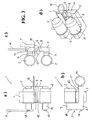
- Figure 1 shows diagrammatically a front view ( Figure 1a ), a side view ( Figure 1b ), a bottom view ( Figure 1c ) and a perspective view ( Figure 1d ) of a first embodiment of a transducer 1 made according to the invention.
- the transducer 1 comprises, in combination with each other, at least:
- the at least one seat 8 is preferably a seat having a swallow-tailed profile and is placed at the centre of at least one of the areas of the central part 4 of the body 3 which are situated at the sides of the recess 6.
- the fixed body 3 and the moveable element 7 are formed - primarily for reasons of economy - from sections obtained by extrusion, but without departing from the scope of the invention they may be obtained by working with a machine tool or by casting.
- the measuring means can advantageously be connected, by means of the cable 14, to a logic unit (omitted in the appended figures for the sake of simplicity of the graphic representation and not described because it is per se known) able to process the electrical signals generated by the measuring means, to display the tension of the cable 13 thus detected and, possibly, to transmit the measurement read to a remote control unit or to generate an alarm signal or a control and feedback signal (analogical or digital).
- a logic unit included in the appended figures for the sake of simplicity of the graphic representation and not described because it is per se known
- the moveable element 7 is preferably held in the working position also by a safety release pin 16 inserted in through holes (not shown in the appended figures) formed in the fixed body 3 and in the moveable element 7 and held in place by a bent portion 17 thereof which engages with the central part 4 of the fixed body 3.
- the recess delimited by the fixed body 3 and by the transmission elements 2 is open on one side, allowing the cable 13 to be inserted in the transducer 1 (and the transducer 1 to be removed from the cable 13) very easily when the smaller arm 10 of the moveable element 7, in its resting position (that is, rotated 90° with respect to the position in the appended figures), is contained in the recess 6 present in the central part 4 of the fixed body 3.
- the transmission elements 2 are advantageously provided with pins to be inserted in through holes formed at the end of the arms 5 and fixed therein by means of reversible fixing means 18 (for example, by means of snap rings) so as to be able to be easily removed and replaced: this allows the transmission elements 2 to be adapted to the characteristics (shape, size, etc.) of the cable to be controlled by mounting on the ends of the arms 5 transmission elements 2 having an outer profile complementary to that of the cable 13.
- the position of the points of contact of the cable 13 with the transmission elements 2 is changed with respect to the point of contact of said cable with the arm 10, thus changing the field of measurement of the transducer and making it compatible with tensioning values of the cable that are different from each other (larger or smaller), without having to change the dimensions of the fixed body 3 and of the moveable element 7.
- the change in the field of measurement of the transducer can further be obtained by changing the position of the axis 9 and, consequently, that of the at least one seat 8.
- the transmission elements 2 have semicircular grooves 12 able to receive a (substantially) cylindrical cable, whilst in the embodiment shown in Figure 3 the transmission elements 2 have a cylindrical shape suitable to receive a (substantially) flat cable.
- the transmission elements 2 can be made rotatable with respect to the relative pins (for example through interposition of ball bearings or of other rolling means) to allow the transducer 1 to be applied also to cables in relative movement with respect to the transducer 1.
- the arm 10 of the moveable element 7 advantageously has a cam profile able to move the cable progressively out of alignment during setting up thereof so as to reduce the effort required to the operator and so as not to stress the fixed body 3 beyond its limit of elastic deformation and the end of the arm 10 has an outer profile complementary to that of the cable 13; in the embodiment shown in Figures 1 and 2 the end of the arm 10 of the moveable element 7 has a semicircular groove 11 similar to the semicircular grooves 12 of the transmission elements 2, whilst in the embodiment shown in Figure 3 the end of the arm 10 of the moveable element 7 has a rounded surface 40.
- the groove 11 present in the end of the arm 10 can be made in the sleeve of a cylindrical body rotatable around an axis, at right angles to the direction of travel of the cable, carried on the end of the arm 10 of the moveable element 7.
- the dimensions of the transmission elements 2 at the grooves 12 and those of the end of the arm 10 of the moveable element 7 at the groove 11 are such as not to stress the cable 13 in such a limited area as to cause permanent deformations and/or damages thereof.
- the semicircular shape of the semicircular groves 11 and 12 ( Figures 1 and 2 ) is such as make the position of the cable certain when the transducer 1 is applied thereto, thus making certain the distribution of stresses within the fixed body 3.
- the transducer 1 of the present invention can be applied fixedly to the cable 13, so as to form a permanent element controlling the tension of the cable 13, or temporarily, as needed or at pre-established intervals, to control the correct tensioning of the cable.
- Figure 2 shows diagrammatically a front view, a side view, a bottom view and a perspective view of a transducer 1 which differs from that of Figure 1 in the arrangement of the release pin 16 which, instead of being inserted in the through holes formed in the fixed body 3 and in the moveable element 7, is inserted only in the through hole formed in the moveable element 7 and rests against the bottom wall of the at least one seat 8 of the fixed body 3 and is held in place by a bent portion 17 thereof which engages with the central part 4) of the fixed body 3.
- Figure 3 shows diagrammatically a front view, a side view, a bottom view and a perspective view of a second embodiment of a transducer 1 made according to the invention, which differs from that shown in Figures 1 or 2 essentially in that it is designed to measure tensioning of a flat cable.
- the transmission elements 2 are cylindrical in shape and the end of the smaller arm 10 of the moveable element 7 has a rounded surface 40 able to receive a (substantially) flat cable.
- the transmission elements 2 have side shoulders which determine a certain positioning of the cable with respect to the axis of the transmission 2, thus causing a certain distribution of the stresses inside the fixed body 3.
- the transmission elements 2 can be made rotatable with respective to the relative pins and the rounded surface 40 can be equipped with rolling means (for example with rotatable rollers), not shown in Figure 3 for simplicity of the graphic representation.
Landscapes
- Physics & Mathematics (AREA)
- General Physics & Mathematics (AREA)
- Chemical & Material Sciences (AREA)
- Analytical Chemistry (AREA)
- Force Measurement Appropriate To Specific Purposes (AREA)
- Arrangements For Transmission Of Measured Signals (AREA)
- Emergency Protection Circuit Devices (AREA)
- Testing Relating To Insulation (AREA)
Claims (14)
- Capteur (1) pour la mesure de la tension de câbles (13), comprenant en combinaison les uns avec les autres, au moins :- un corps fixe (3), ayant un profilé en forme de C et comprenant une partie centrale (4) et une paire de bras (5), la partie centrale (4) du corps fixe (3) ayant une cavité (6) dans laquelle un élément déplaçable en forme de L (7) est inséré, un siège (8) étant formé dans au moins une des zones de la partie centrale (4) située au niveau des côtés de la cavité (6), qui constitue une réduction localisée de la section résistante de la structure mécanique du corps fixe (3) ;- une paire d'éléments de transmission (2), dont chacun est maintenu de manière à se projeter par un des bras (5) du corps fixe (3) ;- l'élément déplaçable en forme de L (7), apte à entrer en rotation autour d'un axe (9) situé dans deux sièges formés sur le côté des bras (5) du corps fixe (3), dans les zones de la partie centrale (4) situées au niveau des côtés de la cavité (6) comprend un bras (10) plus petit par lequel le câble (13) est désaligné lorsque ledit élément déplaçable (7) est dans la position de travail et un bras plus long ;- un moyen de mesure, situé dans au moins un siège (8) du corps fixe (3) et apte à mesurer la déformation induite dans le corps fixe (3) par un câble (13) reposant sur les éléments de transmission (2) et à l'extrémité dudit bras plus petit (10) de l'élément déplaçable (7) et désaligné par ledit bras plus petit (10) quand l'élément déplaçable (7) est dans la position de travail ;moyennant quoi ledit bras plus long de l'élément déplaçable (7)- est suffisamment long pour permettre à un opérateur d'amener ledit bras plus long dans la position de travail même avec un câble déjà tendu, sans devoir se servir d'un outil, et- est gardé dans la position de travail par un moyen de rétention constitué d'un élément élastique (15) placé à l'extrémité dudit bras plus long, qui vient en prise avec un siège (20) formé dans le corps fixe (3).
- Capteur (1) selon la revendication 1, caractérisé en ce que le bras plus petit (10) de l'élément déplaçable (7) possède un profil de came apte à désaligner progressivement le câble (13) pendant l'installation de l'élément déplaçable (7), afin de réduire l'effort requis de l'opérateur et de ne pas contraindre le corps fixe (3) au-delà de ses limites de déformation élastique.
- Capteur (1) selon la revendication 1, caractérisé en ce que il comprend en outre une goupille de déverrouillage (16) apte à retenir l'élément déplaçable (7) dans la position de travail.
- Capteur (1) selon la revendication 3, caractérisé en ce que la goupille de déverrouillage (16) est insérée dans des alésages traversants formés dans le corps fixe (3) et dans l'élément déplaçable (7) et est maintenue en place par une portion courbe (17) de celui-ci qui vient en prise avec la partie centrale (4) du corps fixe (3).
- Capteur selon la revendication 3, caractérisé en ce que la goupille de déverrouillage (16) est insérée dans un alésage traversant formé dans l'élément déplaçable (7), repose contre la paroi de fond d'au moins un siège (8) du corps fixe (3) et est maintenue en place par une portion courbe (17) de celui-ci qui vient en prise avec la partie centrale (4) du corps fixe (3).
- Capteur (1) selon la revendication 1, caractérisé en ce que le moyen de mesure consiste en des jauges de contrainte linéaire ou en un autre élément apte à mesurer des déformations à l'intérieur du corps fixe (3).
- Capteur (1) selon la revendication 1, caractérisé en ce que le moyen de mesure est connecté, au moyen d'un câble (14), à une unité logique apte à traiter les signaux électriques générés par le moyen de mesure et à afficher la tension du câble (13).
- Capteur (1) selon la revendication 1, caractérisé en ce que les éléments de transmission (2) sont pourvus de goupilles à insérer dans les alésages traversants formés aux extrémités des bras (5) du corps fixe (3) et fixées dans celui-ci au moyen de moyens de fixation réversibles (18).
- Capteur (1) selon la revendication 8, caractérisé en ce que les éléments de transmission (2) peuvent être tournés par rapport aux goupilles relatives.
- Capteur (1) selon la revendication 1, caractérisé en ce que les éléments de transmission (2) et l'extrémité du bras (10) de l'élément déplaçable (7) possèdent un profil complémentaire de celui du câble (13).
- Capteur (1) selon la revendication 10, caractérisé en ce que les éléments de transmission (2) et l'extrémité du bras (10) de l'élément déplaçable (7) possèdent des gorges semi-circulaires (12 et 11, respectivement).
- Capteur (1) selon la revendication 11, caractérisé en ce que la gorge semi-circulaire (11) qui est présente à l'extrémité du bras (10) de l'élément déplaçable (7) est formée dans le manchon d'un corps cylindrique, pouvant entrer en rotation autour d'un axe à angle droit par rapport à la direction de course du câble, supporté par l'extrémité du bras (10) de l'élément déplaçable (7).
- Capteur (1) selon la revendication 10, caractérisé en ce que les éléments de transmission (2) sont de forme cylindrique et en ce que l'extrémité du bras (10) de l'élément déplaçable (7) possède une surface arrondie (40).
- Capteur (1) selon la revendication 16, caractérisé en ce que la surface arrondie (40) est équipée de moyens de roulement.
Priority Applications (4)
| Application Number | Priority Date | Filing Date | Title |
|---|---|---|---|
| AT05425245T ATE432461T1 (de) | 2005-04-19 | 2005-04-19 | Aufnehmer zur messung einer kabelspannung |
| DE602005014616T DE602005014616D1 (de) | 2005-04-19 | 2005-04-19 | Aufnehmer zur Messung einer Kabelspannung |
| EP05425245A EP1715318B1 (fr) | 2005-04-19 | 2005-04-19 | Capteur pour la mesure de la tension d'un câble |
| ES05425245T ES2326985T3 (es) | 2005-04-19 | 2005-04-19 | Transductor para medir el tensado de cables. |
Applications Claiming Priority (1)
| Application Number | Priority Date | Filing Date | Title |
|---|---|---|---|
| EP05425245A EP1715318B1 (fr) | 2005-04-19 | 2005-04-19 | Capteur pour la mesure de la tension d'un câble |
Publications (2)
| Publication Number | Publication Date |
|---|---|
| EP1715318A1 EP1715318A1 (fr) | 2006-10-25 |
| EP1715318B1 true EP1715318B1 (fr) | 2009-05-27 |
Family
ID=34977108
Family Applications (1)
| Application Number | Title | Priority Date | Filing Date |
|---|---|---|---|
| EP05425245A Expired - Lifetime EP1715318B1 (fr) | 2005-04-19 | 2005-04-19 | Capteur pour la mesure de la tension d'un câble |
Country Status (4)
| Country | Link |
|---|---|
| EP (1) | EP1715318B1 (fr) |
| AT (1) | ATE432461T1 (fr) |
| DE (1) | DE602005014616D1 (fr) |
| ES (1) | ES2326985T3 (fr) |
Families Citing this family (1)
| Publication number | Priority date | Publication date | Assignee | Title |
|---|---|---|---|---|
| NL2038034B1 (en) * | 2024-06-24 | 2026-01-15 | Adjuvo Motion B V | A cable force measuring device |
Family Cites Families (7)
| Publication number | Priority date | Publication date | Assignee | Title |
|---|---|---|---|---|
| GB1241321A (en) * | 1967-07-13 | 1971-08-04 | Norseman Cable Measurements Lt | Improvements in or relating to apparatus for testing elongate members |
| US3879999A (en) * | 1973-05-02 | 1975-04-29 | Erwin J Saxl | Tension meters |
| DE2429668A1 (de) * | 1974-06-20 | 1976-01-08 | Volkswagenwerk Ag | Vorrichtung zur ermittlung der zugkraft in einem seil- oder bandfoermigen messobjekt |
| US4989450A (en) * | 1989-08-01 | 1991-02-05 | Gse, Inc. | Cable tensiometer |
| BE1006616A3 (fr) * | 1993-01-26 | 1994-11-03 | Fernand Humblet | Capteur de force. |
| SE9600636L (sv) * | 1996-02-20 | 1997-08-21 | Lars Kenneth Baecklund | Spännkraftsmätare |
| JPH1130558A (ja) * | 1997-07-10 | 1999-02-02 | Anzen Motor Car Co Ltd | ベルト張力測定器 |
-
2005
- 2005-04-19 AT AT05425245T patent/ATE432461T1/de not_active IP Right Cessation
- 2005-04-19 DE DE602005014616T patent/DE602005014616D1/de not_active Expired - Lifetime
- 2005-04-19 ES ES05425245T patent/ES2326985T3/es not_active Expired - Lifetime
- 2005-04-19 EP EP05425245A patent/EP1715318B1/fr not_active Expired - Lifetime
Also Published As
| Publication number | Publication date |
|---|---|
| ATE432461T1 (de) | 2009-06-15 |
| EP1715318A1 (fr) | 2006-10-25 |
| ES2326985T3 (es) | 2009-10-22 |
| DE602005014616D1 (de) | 2009-07-09 |
Similar Documents
| Publication | Publication Date | Title |
|---|---|---|
| EP2062845B1 (fr) | Portique de levage et de translation, à usage pédagogique ou industriel | |
| US10273128B2 (en) | Rope hoist | |
| WO1982002815A1 (fr) | Appareil de detection du tirage d'un tracteur | |
| EP1715318B1 (fr) | Capteur pour la mesure de la tension d'un câble | |
| CN102798495B (zh) | 张力检测机构 | |
| EP0084035A1 (fr) | Levier de commande actionne manuellement | |
| US4120197A (en) | Device for sensing exerted load on a rope, wire, or the like | |
| EP1136220A2 (fr) | Mécanisme de serrage de moule pour machine à mouler | |
| EP0649686A1 (fr) | Laminoir à déplacement axial | |
| EP3315452B1 (fr) | Dispositif de support d'un câble d'un cabestan d'une grue | |
| US4433586A (en) | Electronic cable load gauge | |
| KR20200067390A (ko) | 케이블 벤딩 장치 | |
| WO2021209300A1 (fr) | Dispositif de mesure permettant la mesure d'un diamètre de câble | |
| EP2767813B1 (fr) | Capteur de mesure de tensions mécaniques, adaptable à des câbles de différent calibre | |
| KR102587280B1 (ko) | 반목 시스템 | |
| JP6044514B2 (ja) | スラスト力測定装置及び圧延機 | |
| KR200453287Y1 (ko) | 로프 장력 측정장치 | |
| EP3095532B1 (fr) | Unité de serrage pour appareils de roulement | |
| JP6288154B2 (ja) | 移動式クレーンの伸縮ビーム抜け出し防止用検知装置及び移動式クレーン | |
| JP2006250557A5 (fr) | ||
| KR100805017B1 (ko) | 와이어 로프 마모량 측정장치 | |
| KR102587279B1 (ko) | 반목 장치 | |
| CN113043301B (zh) | 一种力矩可调节传感装置和自锁型机械手 | |
| JP5976515B2 (ja) | トロリ線摩耗検出装置 | |
| KR101685907B1 (ko) | 스트랜드 가이딩 소자 |
Legal Events
| Date | Code | Title | Description |
|---|---|---|---|
| PUAI | Public reference made under article 153(3) epc to a published international application that has entered the european phase |
Free format text: ORIGINAL CODE: 0009012 |
|
| AK | Designated contracting states |
Kind code of ref document: A1 Designated state(s): AT BE BG CH CY CZ DE DK EE ES FI FR GB GR HU IE IS IT LI LT LU MC NL PL PT RO SE SI SK TR |
|
| AX | Request for extension of the european patent |
Extension state: AL BA HR LV MK YU |
|
| 17P | Request for examination filed |
Effective date: 20070424 |
|
| AKX | Designation fees paid |
Designated state(s): AT BE BG CH CY CZ DE DK EE ES FI FR GB GR HU IE IS IT LI LT LU MC NL PL PT RO SE SI SK TR |
|
| GRAJ | Information related to disapproval of communication of intention to grant by the applicant or resumption of examination proceedings by the epo deleted |
Free format text: ORIGINAL CODE: EPIDOSDIGR1 |
|
| GRAP | Despatch of communication of intention to grant a patent |
Free format text: ORIGINAL CODE: EPIDOSNIGR1 |
|
| GRAP | Despatch of communication of intention to grant a patent |
Free format text: ORIGINAL CODE: EPIDOSNIGR1 |
|
| GRAS | Grant fee paid |
Free format text: ORIGINAL CODE: EPIDOSNIGR3 |
|
| GRAA | (expected) grant |
Free format text: ORIGINAL CODE: 0009210 |
|
| AK | Designated contracting states |
Kind code of ref document: B1 Designated state(s): AT BE BG CH CY CZ DE DK EE ES FI FR GB GR HU IE IS IT LI LT LU MC NL PL PT RO SE SI SK TR |
|
| REG | Reference to a national code |
Ref country code: GB Ref legal event code: FG4D |
|
| REG | Reference to a national code |
Ref country code: CH Ref legal event code: EP |
|
| REG | Reference to a national code |
Ref country code: IE Ref legal event code: FG4D |
|
| REF | Corresponds to: |
Ref document number: 602005014616 Country of ref document: DE Date of ref document: 20090709 Kind code of ref document: P |
|
| REG | Reference to a national code |
Ref country code: ES Ref legal event code: FG2A Ref document number: 2326985 Country of ref document: ES Kind code of ref document: T3 |
|
| PG25 | Lapsed in a contracting state [announced via postgrant information from national office to epo] |
Ref country code: FI Free format text: LAPSE BECAUSE OF FAILURE TO SUBMIT A TRANSLATION OF THE DESCRIPTION OR TO PAY THE FEE WITHIN THE PRESCRIBED TIME-LIMIT Effective date: 20090527 Ref country code: PT Free format text: LAPSE BECAUSE OF FAILURE TO SUBMIT A TRANSLATION OF THE DESCRIPTION OR TO PAY THE FEE WITHIN THE PRESCRIBED TIME-LIMIT Effective date: 20090927 Ref country code: LT Free format text: LAPSE BECAUSE OF FAILURE TO SUBMIT A TRANSLATION OF THE DESCRIPTION OR TO PAY THE FEE WITHIN THE PRESCRIBED TIME-LIMIT Effective date: 20090527 Ref country code: AT Free format text: LAPSE BECAUSE OF FAILURE TO SUBMIT A TRANSLATION OF THE DESCRIPTION OR TO PAY THE FEE WITHIN THE PRESCRIBED TIME-LIMIT Effective date: 20090527 |
|
| NLV1 | Nl: lapsed or annulled due to failure to fulfill the requirements of art. 29p and 29m of the patents act | ||
| PG25 | Lapsed in a contracting state [announced via postgrant information from national office to epo] |
Ref country code: SI Free format text: LAPSE BECAUSE OF FAILURE TO SUBMIT A TRANSLATION OF THE DESCRIPTION OR TO PAY THE FEE WITHIN THE PRESCRIBED TIME-LIMIT Effective date: 20090527 Ref country code: NL Free format text: LAPSE BECAUSE OF FAILURE TO SUBMIT A TRANSLATION OF THE DESCRIPTION OR TO PAY THE FEE WITHIN THE PRESCRIBED TIME-LIMIT Effective date: 20090527 Ref country code: PL Free format text: LAPSE BECAUSE OF FAILURE TO SUBMIT A TRANSLATION OF THE DESCRIPTION OR TO PAY THE FEE WITHIN THE PRESCRIBED TIME-LIMIT Effective date: 20090527 Ref country code: SE Free format text: LAPSE BECAUSE OF FAILURE TO SUBMIT A TRANSLATION OF THE DESCRIPTION OR TO PAY THE FEE WITHIN THE PRESCRIBED TIME-LIMIT Effective date: 20090827 Ref country code: IS Free format text: LAPSE BECAUSE OF FAILURE TO SUBMIT A TRANSLATION OF THE DESCRIPTION OR TO PAY THE FEE WITHIN THE PRESCRIBED TIME-LIMIT Effective date: 20090927 |
|
| PG25 | Lapsed in a contracting state [announced via postgrant information from national office to epo] |
Ref country code: RO Free format text: LAPSE BECAUSE OF FAILURE TO SUBMIT A TRANSLATION OF THE DESCRIPTION OR TO PAY THE FEE WITHIN THE PRESCRIBED TIME-LIMIT Effective date: 20090527 Ref country code: EE Free format text: LAPSE BECAUSE OF FAILURE TO SUBMIT A TRANSLATION OF THE DESCRIPTION OR TO PAY THE FEE WITHIN THE PRESCRIBED TIME-LIMIT Effective date: 20090527 Ref country code: DK Free format text: LAPSE BECAUSE OF FAILURE TO SUBMIT A TRANSLATION OF THE DESCRIPTION OR TO PAY THE FEE WITHIN THE PRESCRIBED TIME-LIMIT Effective date: 20090527 Ref country code: CZ Free format text: LAPSE BECAUSE OF FAILURE TO SUBMIT A TRANSLATION OF THE DESCRIPTION OR TO PAY THE FEE WITHIN THE PRESCRIBED TIME-LIMIT Effective date: 20090527 |
|
| PG25 | Lapsed in a contracting state [announced via postgrant information from national office to epo] |
Ref country code: SK Free format text: LAPSE BECAUSE OF FAILURE TO SUBMIT A TRANSLATION OF THE DESCRIPTION OR TO PAY THE FEE WITHIN THE PRESCRIBED TIME-LIMIT Effective date: 20090527 Ref country code: BE Free format text: LAPSE BECAUSE OF FAILURE TO SUBMIT A TRANSLATION OF THE DESCRIPTION OR TO PAY THE FEE WITHIN THE PRESCRIBED TIME-LIMIT Effective date: 20090527 |
|
| PG25 | Lapsed in a contracting state [announced via postgrant information from national office to epo] |
Ref country code: BG Free format text: LAPSE BECAUSE OF FAILURE TO SUBMIT A TRANSLATION OF THE DESCRIPTION OR TO PAY THE FEE WITHIN THE PRESCRIBED TIME-LIMIT Effective date: 20090827 |
|
| PLBE | No opposition filed within time limit |
Free format text: ORIGINAL CODE: 0009261 |
|
| STAA | Information on the status of an ep patent application or granted ep patent |
Free format text: STATUS: NO OPPOSITION FILED WITHIN TIME LIMIT |
|
| 26N | No opposition filed |
Effective date: 20100302 |
|
| PG25 | Lapsed in a contracting state [announced via postgrant information from national office to epo] |
Ref country code: GR Free format text: LAPSE BECAUSE OF FAILURE TO SUBMIT A TRANSLATION OF THE DESCRIPTION OR TO PAY THE FEE WITHIN THE PRESCRIBED TIME-LIMIT Effective date: 20090828 |
|
| PG25 | Lapsed in a contracting state [announced via postgrant information from national office to epo] |
Ref country code: MC Free format text: LAPSE BECAUSE OF NON-PAYMENT OF DUE FEES Effective date: 20100430 |
|
| REG | Reference to a national code |
Ref country code: CH Ref legal event code: PL |
|
| REG | Reference to a national code |
Ref country code: IE Ref legal event code: MM4A |
|
| PG25 | Lapsed in a contracting state [announced via postgrant information from national office to epo] |
Ref country code: IE Free format text: LAPSE BECAUSE OF NON-PAYMENT OF DUE FEES Effective date: 20100419 |
|
| PG25 | Lapsed in a contracting state [announced via postgrant information from national office to epo] |
Ref country code: CH Free format text: LAPSE BECAUSE OF NON-PAYMENT OF DUE FEES Effective date: 20100430 Ref country code: LI Free format text: LAPSE BECAUSE OF NON-PAYMENT OF DUE FEES Effective date: 20100430 |
|
| PG25 | Lapsed in a contracting state [announced via postgrant information from national office to epo] |
Ref country code: CY Free format text: LAPSE BECAUSE OF FAILURE TO SUBMIT A TRANSLATION OF THE DESCRIPTION OR TO PAY THE FEE WITHIN THE PRESCRIBED TIME-LIMIT Effective date: 20090527 |
|
| PG25 | Lapsed in a contracting state [announced via postgrant information from national office to epo] |
Ref country code: LU Free format text: LAPSE BECAUSE OF NON-PAYMENT OF DUE FEES Effective date: 20100419 Ref country code: HU Free format text: LAPSE BECAUSE OF FAILURE TO SUBMIT A TRANSLATION OF THE DESCRIPTION OR TO PAY THE FEE WITHIN THE PRESCRIBED TIME-LIMIT Effective date: 20091128 |
|
| PG25 | Lapsed in a contracting state [announced via postgrant information from national office to epo] |
Ref country code: TR Free format text: LAPSE BECAUSE OF FAILURE TO SUBMIT A TRANSLATION OF THE DESCRIPTION OR TO PAY THE FEE WITHIN THE PRESCRIBED TIME-LIMIT Effective date: 20090527 |
|
| PGFP | Annual fee paid to national office [announced via postgrant information from national office to epo] |
Ref country code: GB Payment date: 20140428 Year of fee payment: 10 |
|
| PGFP | Annual fee paid to national office [announced via postgrant information from national office to epo] |
Ref country code: FR Payment date: 20140417 Year of fee payment: 10 Ref country code: DE Payment date: 20140429 Year of fee payment: 10 Ref country code: IT Payment date: 20140305 Year of fee payment: 10 Ref country code: ES Payment date: 20140428 Year of fee payment: 10 |
|
| REG | Reference to a national code |
Ref country code: DE Ref legal event code: R119 Ref document number: 602005014616 Country of ref document: DE |
|
| GBPC | Gb: european patent ceased through non-payment of renewal fee |
Effective date: 20150419 |
|
| PG25 | Lapsed in a contracting state [announced via postgrant information from national office to epo] |
Ref country code: IT Free format text: LAPSE BECAUSE OF NON-PAYMENT OF DUE FEES Effective date: 20150419 Ref country code: DE Free format text: LAPSE BECAUSE OF NON-PAYMENT OF DUE FEES Effective date: 20151103 Ref country code: GB Free format text: LAPSE BECAUSE OF NON-PAYMENT OF DUE FEES Effective date: 20150419 |
|
| REG | Reference to a national code |
Ref country code: FR Ref legal event code: ST Effective date: 20151231 |
|
| PG25 | Lapsed in a contracting state [announced via postgrant information from national office to epo] |
Ref country code: FR Free format text: LAPSE BECAUSE OF NON-PAYMENT OF DUE FEES Effective date: 20150430 |
|
| REG | Reference to a national code |
Ref country code: ES Ref legal event code: FD2A Effective date: 20160527 |
|
| PG25 | Lapsed in a contracting state [announced via postgrant information from national office to epo] |
Ref country code: ES Free format text: LAPSE BECAUSE OF NON-PAYMENT OF DUE FEES Effective date: 20150420 |