EP1715318B1 - Transducer for measurement of cable tensioning - Google Patents
Transducer for measurement of cable tensioning Download PDFInfo
- Publication number
- EP1715318B1 EP1715318B1 EP05425245A EP05425245A EP1715318B1 EP 1715318 B1 EP1715318 B1 EP 1715318B1 EP 05425245 A EP05425245 A EP 05425245A EP 05425245 A EP05425245 A EP 05425245A EP 1715318 B1 EP1715318 B1 EP 1715318B1
- Authority
- EP
- European Patent Office
- Prior art keywords
- fixed body
- transducer
- moveable element
- cable
- arm
- Prior art date
- Legal status (The legal status is an assumption and is not a legal conclusion. Google has not performed a legal analysis and makes no representation as to the accuracy of the status listed.)
- Expired - Lifetime
Links
- 238000005259 measurement Methods 0.000 title abstract description 10
- 230000005540 biological transmission Effects 0.000 claims abstract description 29
- 230000000284 resting effect Effects 0.000 claims abstract description 4
- 230000000295 complement effect Effects 0.000 claims description 3
- 238000005096 rolling process Methods 0.000 claims description 3
- 230000005489 elastic deformation Effects 0.000 claims description 2
- 238000000034 method Methods 0.000 claims description 2
- 230000008569 process Effects 0.000 claims description 2
- 230000009467 reduction Effects 0.000 claims description 2
- 230000002441 reversible effect Effects 0.000 claims description 2
- 238000003780 insertion Methods 0.000 claims 1
- 230000037431 insertion Effects 0.000 claims 1
- 230000008859 change Effects 0.000 description 2
- 238000009434 installation Methods 0.000 description 2
- 230000009471 action Effects 0.000 description 1
- 238000005266 casting Methods 0.000 description 1
- 230000001419 dependent effect Effects 0.000 description 1
- 230000000694 effects Effects 0.000 description 1
- 238000001125 extrusion Methods 0.000 description 1
Images


Classifications
-
- G—PHYSICS
- G01—MEASURING; TESTING
- G01L—MEASURING FORCE, STRESS, TORQUE, WORK, MECHANICAL POWER, MECHANICAL EFFICIENCY, OR FLUID PRESSURE
- G01L5/00—Apparatus for, or methods of, measuring force, work, mechanical power, or torque, specially adapted for specific purposes
- G01L5/04—Apparatus for, or methods of, measuring force, work, mechanical power, or torque, specially adapted for specific purposes for measuring tension in flexible members, e.g. ropes, cables, wires, threads, belts or bands
- G01L5/10—Apparatus for, or methods of, measuring force, work, mechanical power, or torque, specially adapted for specific purposes for measuring tension in flexible members, e.g. ropes, cables, wires, threads, belts or bands using electrical means
- G01L5/107—Apparatus for, or methods of, measuring force, work, mechanical power, or torque, specially adapted for specific purposes for measuring tension in flexible members, e.g. ropes, cables, wires, threads, belts or bands using electrical means for measuring a reaction force applied on an element disposed between two supports, e.g. on a plurality of rollers or gliders
-
- G—PHYSICS
- G01—MEASURING; TESTING
- G01L—MEASURING FORCE, STRESS, TORQUE, WORK, MECHANICAL POWER, MECHANICAL EFFICIENCY, OR FLUID PRESSURE
- G01L5/00—Apparatus for, or methods of, measuring force, work, mechanical power, or torque, specially adapted for specific purposes
- G01L5/04—Apparatus for, or methods of, measuring force, work, mechanical power, or torque, specially adapted for specific purposes for measuring tension in flexible members, e.g. ropes, cables, wires, threads, belts or bands
- G01L5/10—Apparatus for, or methods of, measuring force, work, mechanical power, or torque, specially adapted for specific purposes for measuring tension in flexible members, e.g. ropes, cables, wires, threads, belts or bands using electrical means
- G01L5/102—Apparatus for, or methods of, measuring force, work, mechanical power, or torque, specially adapted for specific purposes for measuring tension in flexible members, e.g. ropes, cables, wires, threads, belts or bands using electrical means using sensors located at a non-interrupted part of the flexible member
Definitions
- the present invention refers to a transducer for measurement of cable tensioning, which can be used to measure both the tension already applied to the cable and the tension that is being applied to the cable during tensioning thereof.
- the transducer according to the invention further allows measurement of the tension both of a fixed cable and of a cable that is moving with respect to the transducer, such as, for example, the cable of lifting means (cranes, winches, elevators, etc.).
- the term “cable” will be used to indicate both a conventional cable (having a circular or a non circular section) and a strip, a tape, a belt or other flat-shaped body.
- Transducers are also known in the art which, when applied to a cable, allow the tension thereof to be measured, but these are complex and bulky devices whose application to the cable is often complicated and whose installation may require the use of specific auxiliary equipments that are not readily found.
- transducers (comparable to load cells), which impose on a plurality of cables a non-rectilinear V-shaped path, can be cited by way of example.
- This type of transducer is extremely bulky and does not allow the tensioning of the individual cables to be known.
- transducers are known in which it is possible to measure tensioning even of a single cable, causing the tensioned cable to pass in a non-rectilinear path through three points and thus determining measurable stresses.
- WO 94/17382 and US3653258 disclose such transducers in which the cable is tensioned by an eccentrically rotating cylinder rotated by a lever arm.
- Object of the present invention is to produce a transducer for measuring tensioning of cables able to overcome the limits presented by the transducers of the prior art; this object is achieved by means of a transducer which has the characteristics illustrated in claim 1.
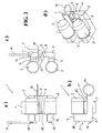
- Figure 1 shows diagrammatically a front view ( Figure 1a ), a side view ( Figure 1b ), a bottom view ( Figure 1c ) and a perspective view ( Figure 1d ) of a first embodiment of a transducer 1 made according to the invention.
- the transducer 1 comprises, in combination with each other, at least:
- the at least one seat 8 is preferably a seat having a swallow-tailed profile and is placed at the centre of at least one of the areas of the central part 4 of the body 3 which are situated at the sides of the recess 6.
- the fixed body 3 and the moveable element 7 are formed - primarily for reasons of economy - from sections obtained by extrusion, but without departing from the scope of the invention they may be obtained by working with a machine tool or by casting.
- the measuring means can advantageously be connected, by means of the cable 14, to a logic unit (omitted in the appended figures for the sake of simplicity of the graphic representation and not described because it is per se known) able to process the electrical signals generated by the measuring means, to display the tension of the cable 13 thus detected and, possibly, to transmit the measurement read to a remote control unit or to generate an alarm signal or a control and feedback signal (analogical or digital).
- a logic unit included in the appended figures for the sake of simplicity of the graphic representation and not described because it is per se known
- the moveable element 7 is preferably held in the working position also by a safety release pin 16 inserted in through holes (not shown in the appended figures) formed in the fixed body 3 and in the moveable element 7 and held in place by a bent portion 17 thereof which engages with the central part 4 of the fixed body 3.
- the recess delimited by the fixed body 3 and by the transmission elements 2 is open on one side, allowing the cable 13 to be inserted in the transducer 1 (and the transducer 1 to be removed from the cable 13) very easily when the smaller arm 10 of the moveable element 7, in its resting position (that is, rotated 90° with respect to the position in the appended figures), is contained in the recess 6 present in the central part 4 of the fixed body 3.
- the transmission elements 2 are advantageously provided with pins to be inserted in through holes formed at the end of the arms 5 and fixed therein by means of reversible fixing means 18 (for example, by means of snap rings) so as to be able to be easily removed and replaced: this allows the transmission elements 2 to be adapted to the characteristics (shape, size, etc.) of the cable to be controlled by mounting on the ends of the arms 5 transmission elements 2 having an outer profile complementary to that of the cable 13.
- the position of the points of contact of the cable 13 with the transmission elements 2 is changed with respect to the point of contact of said cable with the arm 10, thus changing the field of measurement of the transducer and making it compatible with tensioning values of the cable that are different from each other (larger or smaller), without having to change the dimensions of the fixed body 3 and of the moveable element 7.
- the change in the field of measurement of the transducer can further be obtained by changing the position of the axis 9 and, consequently, that of the at least one seat 8.
- the transmission elements 2 have semicircular grooves 12 able to receive a (substantially) cylindrical cable, whilst in the embodiment shown in Figure 3 the transmission elements 2 have a cylindrical shape suitable to receive a (substantially) flat cable.
- the transmission elements 2 can be made rotatable with respect to the relative pins (for example through interposition of ball bearings or of other rolling means) to allow the transducer 1 to be applied also to cables in relative movement with respect to the transducer 1.
- the arm 10 of the moveable element 7 advantageously has a cam profile able to move the cable progressively out of alignment during setting up thereof so as to reduce the effort required to the operator and so as not to stress the fixed body 3 beyond its limit of elastic deformation and the end of the arm 10 has an outer profile complementary to that of the cable 13; in the embodiment shown in Figures 1 and 2 the end of the arm 10 of the moveable element 7 has a semicircular groove 11 similar to the semicircular grooves 12 of the transmission elements 2, whilst in the embodiment shown in Figure 3 the end of the arm 10 of the moveable element 7 has a rounded surface 40.
- the groove 11 present in the end of the arm 10 can be made in the sleeve of a cylindrical body rotatable around an axis, at right angles to the direction of travel of the cable, carried on the end of the arm 10 of the moveable element 7.
- the dimensions of the transmission elements 2 at the grooves 12 and those of the end of the arm 10 of the moveable element 7 at the groove 11 are such as not to stress the cable 13 in such a limited area as to cause permanent deformations and/or damages thereof.
- the semicircular shape of the semicircular groves 11 and 12 ( Figures 1 and 2 ) is such as make the position of the cable certain when the transducer 1 is applied thereto, thus making certain the distribution of stresses within the fixed body 3.
- the transducer 1 of the present invention can be applied fixedly to the cable 13, so as to form a permanent element controlling the tension of the cable 13, or temporarily, as needed or at pre-established intervals, to control the correct tensioning of the cable.
- Figure 2 shows diagrammatically a front view, a side view, a bottom view and a perspective view of a transducer 1 which differs from that of Figure 1 in the arrangement of the release pin 16 which, instead of being inserted in the through holes formed in the fixed body 3 and in the moveable element 7, is inserted only in the through hole formed in the moveable element 7 and rests against the bottom wall of the at least one seat 8 of the fixed body 3 and is held in place by a bent portion 17 thereof which engages with the central part 4) of the fixed body 3.
- Figure 3 shows diagrammatically a front view, a side view, a bottom view and a perspective view of a second embodiment of a transducer 1 made according to the invention, which differs from that shown in Figures 1 or 2 essentially in that it is designed to measure tensioning of a flat cable.
- the transmission elements 2 are cylindrical in shape and the end of the smaller arm 10 of the moveable element 7 has a rounded surface 40 able to receive a (substantially) flat cable.
- the transmission elements 2 have side shoulders which determine a certain positioning of the cable with respect to the axis of the transmission 2, thus causing a certain distribution of the stresses inside the fixed body 3.
- the transmission elements 2 can be made rotatable with respective to the relative pins and the rounded surface 40 can be equipped with rolling means (for example with rotatable rollers), not shown in Figure 3 for simplicity of the graphic representation.
Landscapes
- Physics & Mathematics (AREA)
- General Physics & Mathematics (AREA)
- Chemical & Material Sciences (AREA)
- Analytical Chemistry (AREA)
- Force Measurement Appropriate To Specific Purposes (AREA)
- Arrangements For Transmission Of Measured Signals (AREA)
- Emergency Protection Circuit Devices (AREA)
- Testing Relating To Insulation (AREA)
Abstract
Description
- The present invention refers to a transducer for measurement of cable tensioning, which can be used to measure both the tension already applied to the cable and the tension that is being applied to the cable during tensioning thereof.
- The transducer according to the invention further allows measurement of the tension both of a fixed cable and of a cable that is moving with respect to the transducer, such as, for example, the cable of lifting means (cranes, winches, elevators, etc.).
- In the present description, the term "cable" will be used to indicate both a conventional cable (having a circular or a non circular section) and a strip, a tape, a belt or other flat-shaped body.
- Transducers are also known in the art which, when applied to a cable, allow the tension thereof to be measured, but these are complex and bulky devices whose application to the cable is often complicated and whose installation may require the use of specific auxiliary equipments that are not readily found.
- Among the transducers known in the art, transducers (comparable to load cells), which impose on a plurality of cables a non-rectilinear V-shaped path, can be cited by way of example. This type of transducer is extremely bulky and does not allow the tensioning of the individual cables to be known.
- Furthermore, transducers are known in which it is possible to measure tensioning even of a single cable, causing the tensioned cable to pass in a non-rectilinear path through three points and thus determining measurable stresses.
WO 94/17382 US3653258 disclose such transducers in which the cable is tensioned by an eccentrically rotating cylinder rotated by a lever arm. - Installation of these transducers on a tensioned cable is not easy, in that it is necessary to use special tools, which are not normally available on the market, to position the cable in the transducer as required to make the measurement. Since a lever action must be exerted to overcome the tensioning effect on the cable, it is essential for the installer to have sufficient space and to be able to use both hands.
- The Applicant is not aware of the existence of transducers having characteristics corresponding to those of the present invention.
- Object of the present invention is to produce a transducer for measuring tensioning of cables able to overcome the limits presented by the transducers of the prior art; this object is achieved by means of a transducer which has the characteristics illustrated in
claim 1. - Further advantageous characteristics of the invention form the subject matter of the dependent claims.
- The invention will now be described with reference to exemplary embodiments thereof, in which:
-
Figure 1 shows diagrammatically a front view, a side view, a bottom view and a perspective view of a first embodiment of a transducer made according to the invention; -
Figure 2 shows diagrammatically a front view, a side view, a top view and a perspective view of a transducer that differs from that offigure 1 in the arrangement of the safety release pin; -
Figure 3 shows diagrammatically a front view, a side view, a bottom view and a perspective view of a second embodiment of a transducer made according to the invention. - In the appended figures corresponding elements will be identified by the same reference numerals.
-
Figure 1 shows diagrammatically a front view (Figure 1a ), a side view (Figure 1b ), a bottom view (Figure 1c ) and a perspective view (Figure 1d ) of a first embodiment of atransducer 1 made according to the invention. - The
transducer 1 comprises, in combination with each other, at least: - a
fixed body 3, having a C-shaped profile (Figure 1b ) and comprising acentral part 4 and a pair ofarms 5; in thecentral part 4 of thefixed body 3 there is a recess 6 (Figures 1a and 1d ) in which amoveable element 7 is inserted, whilst in at least one of the areas of thecentral part 4 situated at the sides of therecess 6 there is a seat 8 (Figure 1b ) to which a reduction in the resistant section of the mechanical structure of the transducer, functional to measurement of the stress deriving from the tensioning of the cable, corresponds; - a pair of
transmission elements 2, each of which is held projectingly by one of thearms 5 of thefixed body 3; - the
moveable element 7 is L-shaped (Figure 1b ) and able to rotate around anaxis 9 situated in two seats (not identified by means of a reference numeral because they are occupied by the axis 9) formed on the side of thearms 5 in the areas of thecentral part 4 which are situated at the sides of therecess 6; thesmaller arm 10 of themoveable element 7 is able to move out of alignment, when in the working position, a cable 13 (indicated with dashed lines inFigure 1b and omitted in the other figures for the sake of simplicity of the graphic representation) resting on thetransmission elements 2 and on the end of thearm 10 of themoveable element 7, whilst the other arm of themoveable element 7 is sufficiently long to allow an operator to bring thearm 10 of theelement 7 into the working position even with an already tensioned cable, without having to resort to a tool and it is kept in the working position by retaining means consisting, in the embodiment described herein, of an elastic element 15 (Figure 1b ) which engages in a seat 20 (Figure 2c ) formed in thefixed body 3; - measuring means placed in the at least one
seat 8 of thefixed body 3 and able to measure the deformation induced in thebody 3, by means of thetransmission elements 2 and of thearm 10 of themoveable element 7 by thecable 13 when it is moved out of alignment by thearm 10 of theelement 7; the measuring means (omitted in the appended figures for the sake of simplicity of the graphic representation) preferably consist of linear strain gauges or of other functionally equivalent means, per se known, which will not therefore be described. - The at least one
seat 8 is preferably a seat having a swallow-tailed profile and is placed at the centre of at least one of the areas of thecentral part 4 of thebody 3 which are situated at the sides of therecess 6. - The
fixed body 3 and themoveable element 7 are formed - primarily for reasons of economy - from sections obtained by extrusion, but without departing from the scope of the invention they may be obtained by working with a machine tool or by casting. - The measuring means can advantageously be connected, by means of the
cable 14, to a logic unit (omitted in the appended figures for the sake of simplicity of the graphic representation and not described because it is per se known) able to process the electrical signals generated by the measuring means, to display the tension of thecable 13 thus detected and, possibly, to transmit the measurement read to a remote control unit or to generate an alarm signal or a control and feedback signal (analogical or digital). - The
moveable element 7 is preferably held in the working position also by asafety release pin 16 inserted in through holes (not shown in the appended figures) formed in thefixed body 3 and in themoveable element 7 and held in place by abent portion 17 thereof which engages with thecentral part 4 of thefixed body 3. - By virtue of the C-shape of the
fixed body 3 and of the fact that thetransmission elements 2 are mounted projectingly on the ends of thearms 5 of thefixed body 3, the recess delimited by thefixed body 3 and by thetransmission elements 2 is open on one side, allowing thecable 13 to be inserted in the transducer 1 (and thetransducer 1 to be removed from the cable 13) very easily when thesmaller arm 10 of themoveable element 7, in its resting position (that is, rotated 90° with respect to the position in the appended figures), is contained in therecess 6 present in thecentral part 4 of thefixed body 3. - Furthermore the
transmission elements 2 are advantageously provided with pins to be inserted in through holes formed at the end of thearms 5 and fixed therein by means of reversible fixing means 18 (for example, by means of snap rings) so as to be able to be easily removed and replaced: this allows thetransmission elements 2 to be adapted to the characteristics (shape, size, etc.) of the cable to be controlled by mounting on the ends of thearms 5transmission elements 2 having an outer profile complementary to that of thecable 13. - Using
transmission elements 2 having different diameters, without changing the shape and the dimensions of thesemicircular grooves 12, the position of the points of contact of thecable 13 with thetransmission elements 2 is changed with respect to the point of contact of said cable with thearm 10, thus changing the field of measurement of the transducer and making it compatible with tensioning values of the cable that are different from each other (larger or smaller), without having to change the dimensions of thefixed body 3 and of themoveable element 7. The change in the field of measurement of the transducer can further be obtained by changing the position of theaxis 9 and, consequently, that of the at least oneseat 8. - Similarly, it is possible to intervene on the diameter of the
cylindrical transmission elements 2 shown inFigure 3 to adjust the measurement field of thetransducer 1 to different tensioning of the cable. - Purely by way of example it should be observed that in the embodiment shown in
Figures 1 and2 , thetransmission elements 2 havesemicircular grooves 12 able to receive a (substantially) cylindrical cable, whilst in the embodiment shown inFigure 3 thetransmission elements 2 have a cylindrical shape suitable to receive a (substantially) flat cable. - Furthermore, the
transmission elements 2 can be made rotatable with respect to the relative pins (for example through interposition of ball bearings or of other rolling means) to allow thetransducer 1 to be applied also to cables in relative movement with respect to thetransducer 1. - The
arm 10 of themoveable element 7 advantageously has a cam profile able to move the cable progressively out of alignment during setting up thereof so as to reduce the effort required to the operator and so as not to stress thefixed body 3 beyond its limit of elastic deformation and the end of thearm 10 has an outer profile complementary to that of thecable 13; in the embodiment shown inFigures 1 and2 the end of thearm 10 of themoveable element 7 has asemicircular groove 11 similar to thesemicircular grooves 12 of thetransmission elements 2, whilst in the embodiment shown inFigure 3 the end of thearm 10 of themoveable element 7 has arounded surface 40. - To allow the
transducer 1 to be applied also to cables in movement, thegroove 11 present in the end of thearm 10 can be made in the sleeve of a cylindrical body rotatable around an axis, at right angles to the direction of travel of the cable, carried on the end of thearm 10 of themoveable element 7. - The dimensions of the
transmission elements 2 at thegrooves 12 and those of the end of thearm 10 of themoveable element 7 at thegroove 11 are such as not to stress thecable 13 in such a limited area as to cause permanent deformations and/or damages thereof. Furthermore, the semicircular shape of thesemicircular groves 11 and 12 (Figures 1 and2 ) is such as make the position of the cable certain when thetransducer 1 is applied thereto, thus making certain the distribution of stresses within thefixed body 3. - The
transducer 1 of the present invention can be applied fixedly to thecable 13, so as to form a permanent element controlling the tension of thecable 13, or temporarily, as needed or at pre-established intervals, to control the correct tensioning of the cable. -
Figure 2 shows diagrammatically a front view, a side view, a bottom view and a perspective view of atransducer 1 which differs from that ofFigure 1 in the arrangement of therelease pin 16 which, instead of being inserted in the through holes formed in thefixed body 3 and in themoveable element 7, is inserted only in the through hole formed in themoveable element 7 and rests against the bottom wall of the at least oneseat 8 of thefixed body 3 and is held in place by abent portion 17 thereof which engages with the central part 4) of the fixedbody 3. -
Figure 3 shows diagrammatically a front view, a side view, a bottom view and a perspective view of a second embodiment of atransducer 1 made according to the invention, which differs from that shown inFigures 1 or2 essentially in that it is designed to measure tensioning of a flat cable. - For this purpose the
transmission elements 2 are cylindrical in shape and the end of thesmaller arm 10 of themoveable element 7 has arounded surface 40 able to receive a (substantially) flat cable. Thetransmission elements 2 have side shoulders which determine a certain positioning of the cable with respect to the axis of thetransmission 2, thus causing a certain distribution of the stresses inside thefixed body 3.
To allow thetransducer 1 to be applied to a flat cable in movement thetransmission elements 2 can be made rotatable with respective to the relative pins and therounded surface 40 can be equipped with rolling means (for example with rotatable rollers), not shown inFigure 3 for simplicity of the graphic representation. - Without departing from the scope of the invention as defined in the appended claims, a person skilled in the art can make to the transducer previously described changes and improvements suggested by normal experience and/or the evolution of the art.
Claims (14)
- A transducer (1) for measuring the tensioning of cables (13), comprising in combination with each other, at least:- a fixed body (3), having a C-shaped profile and comprising a central part (4) and a pair of arms (5), the central part (4) of the fixed body (3) having a recess (6) in which a L-shaped moveable element (7) is inserted, a seat (8) being formed in at least one of the areas of the central part (4) situated at the sides of the recess (6), which constitutes a localised reduction of the resistant section of the mechanical structure of the fixed body (3);- a pair of transmission elements (2), each of which is held projectingly by one of the arms (5) of the fixed body (3);- the L-shaped moveable element (7), able to rotate around an axis (9) situated in two seats formed, on the side of the arms (5) of the fixed body (3), in the areas of the central part (4) situated at the sides of the recess (6) comprises a smaller arm (10) by which the cable (13) is moved out of alignment when said movable element (7) is in the working position and a longer arm;- measuring means, situated in the at least one seat (8) of the fixed body (3) and able to measure the deformation induced in the fixed body (3) by a cable (13) resting on the transmission elements (2) and on the end of said smaller arm (10) of the moveable element (7) and moved out of alignment by said smaller arm (10) when the moveable element (7) is in the working position; whereby said longer ann of the moveable element (7)- is sufficiently long to allow an operator to bring said longer arm into the working position even with an already tensioned cable, without having to resort to a tool, and- is kept in the working position by retaining means consisting of an elastic element (15), placed at the end of said longer arm, which engages in a seat (20) formed in the fixed body (3).
- A transducer (1) according to claim 1, characterised in that the smaller arm (10) of the moveable element (7) has a cam profile able to progressively move the cable (13) out of alignment during the setting up of the moveable element (7), to reduce the effort required to the operator and not to stress the fixed body (3) beyond its limit of elastic deformation.
- A transducer (1) according to claim 1, characterised in that it further comprises a release pin (16) able to retain the moveable element (7) in the working position.
- A transducer (1) according to claim 3, characterised in that the release pin (16) is inserted in through holes formed in the fixed body (3) and in the moveable element (7) and is held in place by a bent portion (17) thereof which engages with the central part (4) of the fixed body (3).
- A transducer (1) according to claim 3, characterised in that the release pin (16) is inserted in a through hole formed in the moveable element (7), rests against the bottom wall of the at least one seat (8) of the fixed body (3) and is held in place by a bent portion (17) thereof which engages with the central part (4) of the fixed body (3).
- A transducer (1) according to claim 1, characterised in that the measuring means consist of linear stress gauges or of another element able to measure deformations inside the fixed body (3).
- A transducer (1) according to claim 1, characterised in that the measuring means are connected, by means of a cable (14), to a logic unit able to process the electrical signals generated by the measuring means and to display the tension of the cable (13).
- A transducer (1) according to claim 1, characterised in that the transmission elements (2) are provided with pins for insertion in through holes formed at the ends of the arms (5) of the fixed body (3) and fixed therein by means of reversible fixing means (18).
- A transducer (1) according to claim 8, characterised in that the transmission elements (2) are rotatable with respect to the relative pins.
- A transducer (1) according to claim 1, characterised in that the transmission elements (2) and the end of the arm (10) of the moveable element (7) have a profile complementary to that of the cable (13).
- A transducer (1) according to claim 10, characterised in that the transmission elements (2) and the end of the arm (10) of the moveable element (7) have semicircular grooves (12 and 11, respectively).
- A transducer (1) according to claim 11 characterised in that the semicircular groove (11) which is present at the end of the arm (10) of the moveable element (7) is formed in the sleeve of a cylindrical body, rotatable around an axis at right angles to the direction of travel of the cable, carried by the end of the arm (10) of the moveable element (7).
- A transducer (1) according to claim 10, characterised in that the transmission elements (2) are cylindrical in shape and in that the end of the arm (10) of the moveable element (7) has a rounded surface (40).
- A transducer (1) according to claim 16, characterised in that the rounded surface (40) is equipped with rolling means.
Priority Applications (4)
| Application Number | Priority Date | Filing Date | Title |
|---|---|---|---|
| AT05425245T ATE432461T1 (en) | 2005-04-19 | 2005-04-19 | TRANSDUCER FOR MEASURING A CABLE TENSION |
| DE602005014616T DE602005014616D1 (en) | 2005-04-19 | 2005-04-19 | Transducer for measuring a cable voltage |
| EP05425245A EP1715318B1 (en) | 2005-04-19 | 2005-04-19 | Transducer for measurement of cable tensioning |
| ES05425245T ES2326985T3 (en) | 2005-04-19 | 2005-04-19 | TRANSDUCER TO MEASURE CABLE TENSIONING. |
Applications Claiming Priority (1)
| Application Number | Priority Date | Filing Date | Title |
|---|---|---|---|
| EP05425245A EP1715318B1 (en) | 2005-04-19 | 2005-04-19 | Transducer for measurement of cable tensioning |
Publications (2)
| Publication Number | Publication Date |
|---|---|
| EP1715318A1 EP1715318A1 (en) | 2006-10-25 |
| EP1715318B1 true EP1715318B1 (en) | 2009-05-27 |
Family
ID=34977108
Family Applications (1)
| Application Number | Title | Priority Date | Filing Date |
|---|---|---|---|
| EP05425245A Expired - Lifetime EP1715318B1 (en) | 2005-04-19 | 2005-04-19 | Transducer for measurement of cable tensioning |
Country Status (4)
| Country | Link |
|---|---|
| EP (1) | EP1715318B1 (en) |
| AT (1) | ATE432461T1 (en) |
| DE (1) | DE602005014616D1 (en) |
| ES (1) | ES2326985T3 (en) |
Families Citing this family (1)
| Publication number | Priority date | Publication date | Assignee | Title |
|---|---|---|---|---|
| NL2038034B1 (en) * | 2024-06-24 | 2026-01-15 | Adjuvo Motion B V | A cable force measuring device |
Family Cites Families (7)
| Publication number | Priority date | Publication date | Assignee | Title |
|---|---|---|---|---|
| GB1241321A (en) * | 1967-07-13 | 1971-08-04 | Norseman Cable Measurements Lt | Improvements in or relating to apparatus for testing elongate members |
| US3879999A (en) * | 1973-05-02 | 1975-04-29 | Erwin J Saxl | Tension meters |
| DE2429668A1 (en) * | 1974-06-20 | 1976-01-08 | Volkswagenwerk Ag | Tensile load measuring device - deisgned for rope or strip-formed object e.g. seat belt |
| US4989450A (en) * | 1989-08-01 | 1991-02-05 | Gse, Inc. | Cable tensiometer |
| BE1006616A3 (en) * | 1993-01-26 | 1994-11-03 | Fernand Humblet | Force sensor. |
| SE9600636L (en) * | 1996-02-20 | 1997-08-21 | Lars Kenneth Baecklund | Clamp Power Meter |
| JPH1130558A (en) * | 1997-07-10 | 1999-02-02 | Anzen Motor Car Co Ltd | Apparatus for measuring tension of belt |
-
2005
- 2005-04-19 AT AT05425245T patent/ATE432461T1/en not_active IP Right Cessation
- 2005-04-19 DE DE602005014616T patent/DE602005014616D1/en not_active Expired - Lifetime
- 2005-04-19 ES ES05425245T patent/ES2326985T3/en not_active Expired - Lifetime
- 2005-04-19 EP EP05425245A patent/EP1715318B1/en not_active Expired - Lifetime
Also Published As
| Publication number | Publication date |
|---|---|
| ATE432461T1 (en) | 2009-06-15 |
| EP1715318A1 (en) | 2006-10-25 |
| ES2326985T3 (en) | 2009-10-22 |
| DE602005014616D1 (en) | 2009-07-09 |
Similar Documents
| Publication | Publication Date | Title |
|---|---|---|
| EP2062845B1 (en) | Lifting and translation frame, for educational or industrial use | |
| US10273128B2 (en) | Rope hoist | |
| WO1982002815A1 (en) | Tractor draft sensing apparatus | |
| EP1715318B1 (en) | Transducer for measurement of cable tensioning | |
| CN102798495B (en) | Tension force detection mechanism | |
| EP0084035A1 (en) | Manually operated control lever device | |
| US4120197A (en) | Device for sensing exerted load on a rope, wire, or the like | |
| EP1136220A2 (en) | Mold clamping mechanism of molding machine | |
| EP0649686A1 (en) | Rolling mill with axially shifting rolls | |
| EP3315452B1 (en) | Device for supporting a cable of a capstan of a crane | |
| US4433586A (en) | Electronic cable load gauge | |
| KR20200067390A (en) | Apparatus for bending cable | |
| WO2021209300A1 (en) | Measuring device for measuring a cable diameter | |
| EP2767813B1 (en) | Sensor for measuring mechanical stress which can be adapted to cables with different calibers | |
| KR102587280B1 (en) | Keel block system | |
| JP6044514B2 (en) | Thrust force measuring device and rolling mill | |
| KR200453287Y1 (en) | Rope tension measuring device | |
| EP3095532B1 (en) | Tensioning unit for rolling apparatuses | |
| JP6288154B2 (en) | Detecting device for preventing extension beam of mobile crane and mobile crane | |
| JP2006250557A5 (en) | ||
| KR100805017B1 (en) | Wire rope wear amount measuring device | |
| KR102587279B1 (en) | Keel block device | |
| CN113043301B (en) | Moment-adjustable sensing device and self-locking manipulator | |
| JP5976515B2 (en) | Trolley wire wear detector | |
| KR101685907B1 (en) | Strand guiding element |
Legal Events
| Date | Code | Title | Description |
|---|---|---|---|
| PUAI | Public reference made under article 153(3) epc to a published international application that has entered the european phase |
Free format text: ORIGINAL CODE: 0009012 |
|
| AK | Designated contracting states |
Kind code of ref document: A1 Designated state(s): AT BE BG CH CY CZ DE DK EE ES FI FR GB GR HU IE IS IT LI LT LU MC NL PL PT RO SE SI SK TR |
|
| AX | Request for extension of the european patent |
Extension state: AL BA HR LV MK YU |
|
| 17P | Request for examination filed |
Effective date: 20070424 |
|
| AKX | Designation fees paid |
Designated state(s): AT BE BG CH CY CZ DE DK EE ES FI FR GB GR HU IE IS IT LI LT LU MC NL PL PT RO SE SI SK TR |
|
| GRAJ | Information related to disapproval of communication of intention to grant by the applicant or resumption of examination proceedings by the epo deleted |
Free format text: ORIGINAL CODE: EPIDOSDIGR1 |
|
| GRAP | Despatch of communication of intention to grant a patent |
Free format text: ORIGINAL CODE: EPIDOSNIGR1 |
|
| GRAP | Despatch of communication of intention to grant a patent |
Free format text: ORIGINAL CODE: EPIDOSNIGR1 |
|
| GRAS | Grant fee paid |
Free format text: ORIGINAL CODE: EPIDOSNIGR3 |
|
| GRAA | (expected) grant |
Free format text: ORIGINAL CODE: 0009210 |
|
| AK | Designated contracting states |
Kind code of ref document: B1 Designated state(s): AT BE BG CH CY CZ DE DK EE ES FI FR GB GR HU IE IS IT LI LT LU MC NL PL PT RO SE SI SK TR |
|
| REG | Reference to a national code |
Ref country code: GB Ref legal event code: FG4D |
|
| REG | Reference to a national code |
Ref country code: CH Ref legal event code: EP |
|
| REG | Reference to a national code |
Ref country code: IE Ref legal event code: FG4D |
|
| REF | Corresponds to: |
Ref document number: 602005014616 Country of ref document: DE Date of ref document: 20090709 Kind code of ref document: P |
|
| REG | Reference to a national code |
Ref country code: ES Ref legal event code: FG2A Ref document number: 2326985 Country of ref document: ES Kind code of ref document: T3 |
|
| PG25 | Lapsed in a contracting state [announced via postgrant information from national office to epo] |
Ref country code: FI Free format text: LAPSE BECAUSE OF FAILURE TO SUBMIT A TRANSLATION OF THE DESCRIPTION OR TO PAY THE FEE WITHIN THE PRESCRIBED TIME-LIMIT Effective date: 20090527 Ref country code: PT Free format text: LAPSE BECAUSE OF FAILURE TO SUBMIT A TRANSLATION OF THE DESCRIPTION OR TO PAY THE FEE WITHIN THE PRESCRIBED TIME-LIMIT Effective date: 20090927 Ref country code: LT Free format text: LAPSE BECAUSE OF FAILURE TO SUBMIT A TRANSLATION OF THE DESCRIPTION OR TO PAY THE FEE WITHIN THE PRESCRIBED TIME-LIMIT Effective date: 20090527 Ref country code: AT Free format text: LAPSE BECAUSE OF FAILURE TO SUBMIT A TRANSLATION OF THE DESCRIPTION OR TO PAY THE FEE WITHIN THE PRESCRIBED TIME-LIMIT Effective date: 20090527 |
|
| NLV1 | Nl: lapsed or annulled due to failure to fulfill the requirements of art. 29p and 29m of the patents act | ||
| PG25 | Lapsed in a contracting state [announced via postgrant information from national office to epo] |
Ref country code: SI Free format text: LAPSE BECAUSE OF FAILURE TO SUBMIT A TRANSLATION OF THE DESCRIPTION OR TO PAY THE FEE WITHIN THE PRESCRIBED TIME-LIMIT Effective date: 20090527 Ref country code: NL Free format text: LAPSE BECAUSE OF FAILURE TO SUBMIT A TRANSLATION OF THE DESCRIPTION OR TO PAY THE FEE WITHIN THE PRESCRIBED TIME-LIMIT Effective date: 20090527 Ref country code: PL Free format text: LAPSE BECAUSE OF FAILURE TO SUBMIT A TRANSLATION OF THE DESCRIPTION OR TO PAY THE FEE WITHIN THE PRESCRIBED TIME-LIMIT Effective date: 20090527 Ref country code: SE Free format text: LAPSE BECAUSE OF FAILURE TO SUBMIT A TRANSLATION OF THE DESCRIPTION OR TO PAY THE FEE WITHIN THE PRESCRIBED TIME-LIMIT Effective date: 20090827 Ref country code: IS Free format text: LAPSE BECAUSE OF FAILURE TO SUBMIT A TRANSLATION OF THE DESCRIPTION OR TO PAY THE FEE WITHIN THE PRESCRIBED TIME-LIMIT Effective date: 20090927 |
|
| PG25 | Lapsed in a contracting state [announced via postgrant information from national office to epo] |
Ref country code: RO Free format text: LAPSE BECAUSE OF FAILURE TO SUBMIT A TRANSLATION OF THE DESCRIPTION OR TO PAY THE FEE WITHIN THE PRESCRIBED TIME-LIMIT Effective date: 20090527 Ref country code: EE Free format text: LAPSE BECAUSE OF FAILURE TO SUBMIT A TRANSLATION OF THE DESCRIPTION OR TO PAY THE FEE WITHIN THE PRESCRIBED TIME-LIMIT Effective date: 20090527 Ref country code: DK Free format text: LAPSE BECAUSE OF FAILURE TO SUBMIT A TRANSLATION OF THE DESCRIPTION OR TO PAY THE FEE WITHIN THE PRESCRIBED TIME-LIMIT Effective date: 20090527 Ref country code: CZ Free format text: LAPSE BECAUSE OF FAILURE TO SUBMIT A TRANSLATION OF THE DESCRIPTION OR TO PAY THE FEE WITHIN THE PRESCRIBED TIME-LIMIT Effective date: 20090527 |
|
| PG25 | Lapsed in a contracting state [announced via postgrant information from national office to epo] |
Ref country code: SK Free format text: LAPSE BECAUSE OF FAILURE TO SUBMIT A TRANSLATION OF THE DESCRIPTION OR TO PAY THE FEE WITHIN THE PRESCRIBED TIME-LIMIT Effective date: 20090527 Ref country code: BE Free format text: LAPSE BECAUSE OF FAILURE TO SUBMIT A TRANSLATION OF THE DESCRIPTION OR TO PAY THE FEE WITHIN THE PRESCRIBED TIME-LIMIT Effective date: 20090527 |
|
| PG25 | Lapsed in a contracting state [announced via postgrant information from national office to epo] |
Ref country code: BG Free format text: LAPSE BECAUSE OF FAILURE TO SUBMIT A TRANSLATION OF THE DESCRIPTION OR TO PAY THE FEE WITHIN THE PRESCRIBED TIME-LIMIT Effective date: 20090827 |
|
| PLBE | No opposition filed within time limit |
Free format text: ORIGINAL CODE: 0009261 |
|
| STAA | Information on the status of an ep patent application or granted ep patent |
Free format text: STATUS: NO OPPOSITION FILED WITHIN TIME LIMIT |
|
| 26N | No opposition filed |
Effective date: 20100302 |
|
| PG25 | Lapsed in a contracting state [announced via postgrant information from national office to epo] |
Ref country code: GR Free format text: LAPSE BECAUSE OF FAILURE TO SUBMIT A TRANSLATION OF THE DESCRIPTION OR TO PAY THE FEE WITHIN THE PRESCRIBED TIME-LIMIT Effective date: 20090828 |
|
| PG25 | Lapsed in a contracting state [announced via postgrant information from national office to epo] |
Ref country code: MC Free format text: LAPSE BECAUSE OF NON-PAYMENT OF DUE FEES Effective date: 20100430 |
|
| REG | Reference to a national code |
Ref country code: CH Ref legal event code: PL |
|
| REG | Reference to a national code |
Ref country code: IE Ref legal event code: MM4A |
|
| PG25 | Lapsed in a contracting state [announced via postgrant information from national office to epo] |
Ref country code: IE Free format text: LAPSE BECAUSE OF NON-PAYMENT OF DUE FEES Effective date: 20100419 |
|
| PG25 | Lapsed in a contracting state [announced via postgrant information from national office to epo] |
Ref country code: CH Free format text: LAPSE BECAUSE OF NON-PAYMENT OF DUE FEES Effective date: 20100430 Ref country code: LI Free format text: LAPSE BECAUSE OF NON-PAYMENT OF DUE FEES Effective date: 20100430 |
|
| PG25 | Lapsed in a contracting state [announced via postgrant information from national office to epo] |
Ref country code: CY Free format text: LAPSE BECAUSE OF FAILURE TO SUBMIT A TRANSLATION OF THE DESCRIPTION OR TO PAY THE FEE WITHIN THE PRESCRIBED TIME-LIMIT Effective date: 20090527 |
|
| PG25 | Lapsed in a contracting state [announced via postgrant information from national office to epo] |
Ref country code: LU Free format text: LAPSE BECAUSE OF NON-PAYMENT OF DUE FEES Effective date: 20100419 Ref country code: HU Free format text: LAPSE BECAUSE OF FAILURE TO SUBMIT A TRANSLATION OF THE DESCRIPTION OR TO PAY THE FEE WITHIN THE PRESCRIBED TIME-LIMIT Effective date: 20091128 |
|
| PG25 | Lapsed in a contracting state [announced via postgrant information from national office to epo] |
Ref country code: TR Free format text: LAPSE BECAUSE OF FAILURE TO SUBMIT A TRANSLATION OF THE DESCRIPTION OR TO PAY THE FEE WITHIN THE PRESCRIBED TIME-LIMIT Effective date: 20090527 |
|
| PGFP | Annual fee paid to national office [announced via postgrant information from national office to epo] |
Ref country code: GB Payment date: 20140428 Year of fee payment: 10 |
|
| PGFP | Annual fee paid to national office [announced via postgrant information from national office to epo] |
Ref country code: FR Payment date: 20140417 Year of fee payment: 10 Ref country code: DE Payment date: 20140429 Year of fee payment: 10 Ref country code: IT Payment date: 20140305 Year of fee payment: 10 Ref country code: ES Payment date: 20140428 Year of fee payment: 10 |
|
| REG | Reference to a national code |
Ref country code: DE Ref legal event code: R119 Ref document number: 602005014616 Country of ref document: DE |
|
| GBPC | Gb: european patent ceased through non-payment of renewal fee |
Effective date: 20150419 |
|
| PG25 | Lapsed in a contracting state [announced via postgrant information from national office to epo] |
Ref country code: IT Free format text: LAPSE BECAUSE OF NON-PAYMENT OF DUE FEES Effective date: 20150419 Ref country code: DE Free format text: LAPSE BECAUSE OF NON-PAYMENT OF DUE FEES Effective date: 20151103 Ref country code: GB Free format text: LAPSE BECAUSE OF NON-PAYMENT OF DUE FEES Effective date: 20150419 |
|
| REG | Reference to a national code |
Ref country code: FR Ref legal event code: ST Effective date: 20151231 |
|
| PG25 | Lapsed in a contracting state [announced via postgrant information from national office to epo] |
Ref country code: FR Free format text: LAPSE BECAUSE OF NON-PAYMENT OF DUE FEES Effective date: 20150430 |
|
| REG | Reference to a national code |
Ref country code: ES Ref legal event code: FD2A Effective date: 20160527 |
|
| PG25 | Lapsed in a contracting state [announced via postgrant information from national office to epo] |
Ref country code: ES Free format text: LAPSE BECAUSE OF NON-PAYMENT OF DUE FEES Effective date: 20150420 |