EP1715196A1 - Kunststoffplatte zum Auskleiden von Betonbauteilen - Google Patents
Kunststoffplatte zum Auskleiden von Betonbauteilen Download PDFInfo
- Publication number
- EP1715196A1 EP1715196A1 EP05008845A EP05008845A EP1715196A1 EP 1715196 A1 EP1715196 A1 EP 1715196A1 EP 05008845 A EP05008845 A EP 05008845A EP 05008845 A EP05008845 A EP 05008845A EP 1715196 A1 EP1715196 A1 EP 1715196A1
- Authority
- EP
- European Patent Office
- Prior art keywords
- plastic plate
- elements
- plate according
- flow
- flow elements
- Prior art date
- Legal status (The legal status is an assumption and is not a legal conclusion. Google has not performed a legal analysis and makes no representation as to the accuracy of the status listed.)
- Granted
Links
- 238000010276 construction Methods 0.000 title 1
- 239000004033 plastic Substances 0.000 claims abstract description 78
- 238000004873 anchoring Methods 0.000 claims description 19
- 230000000694 effects Effects 0.000 claims description 10
- 239000002245 particle Substances 0.000 claims description 8
- 230000009969 flowable effect Effects 0.000 claims description 6
- 239000000463 material Substances 0.000 claims description 6
- 239000002985 plastic film Substances 0.000 claims description 6
- 238000011144 upstream manufacturing Methods 0.000 claims description 6
- 239000000126 substance Substances 0.000 claims description 5
- 238000003466 welding Methods 0.000 claims description 3
- 230000003287 optical effect Effects 0.000 claims description 2
- 230000007704 transition Effects 0.000 claims 1
- 230000007774 longterm Effects 0.000 description 3
- 230000008901 benefit Effects 0.000 description 2
- 230000015572 biosynthetic process Effects 0.000 description 2
- 239000011888 foil Substances 0.000 description 2
- 239000007788 liquid Substances 0.000 description 2
- 229920001780 ECTFE Polymers 0.000 description 1
- 239000002033 PVDF binder Substances 0.000 description 1
- 238000005299 abrasion Methods 0.000 description 1
- 238000005452 bending Methods 0.000 description 1
- 230000001419 dependent effect Effects 0.000 description 1
- 230000008021 deposition Effects 0.000 description 1
- 238000009415 formwork Methods 0.000 description 1
- 238000012544 monitoring process Methods 0.000 description 1
- 229920002981 polyvinylidene fluoride Polymers 0.000 description 1
- 230000009467 reduction Effects 0.000 description 1
- 239000007787 solid Substances 0.000 description 1
- 239000012815 thermoplastic material Substances 0.000 description 1
Images


Classifications
-
- F—MECHANICAL ENGINEERING; LIGHTING; HEATING; WEAPONS; BLASTING
- F15—FLUID-PRESSURE ACTUATORS; HYDRAULICS OR PNEUMATICS IN GENERAL
- F15D—FLUID DYNAMICS, i.e. METHODS OR MEANS FOR INFLUENCING THE FLOW OF GASES OR LIQUIDS
- F15D1/00—Influencing flow of fluids
- F15D1/02—Influencing flow of fluids in pipes or conduits
- F15D1/06—Influencing flow of fluids in pipes or conduits by influencing the boundary layer
-
- B—PERFORMING OPERATIONS; TRANSPORTING
- B60—VEHICLES IN GENERAL
- B60R—VEHICLES, VEHICLE FITTINGS, OR VEHICLE PARTS, NOT OTHERWISE PROVIDED FOR
- B60R21/00—Arrangements or fittings on vehicles for protecting or preventing injuries to occupants or pedestrians in case of accidents or other traffic risks
- B60R21/02—Occupant safety arrangements or fittings, e.g. crash pads
- B60R21/13—Roll-over protection
-
- F—MECHANICAL ENGINEERING; LIGHTING; HEATING; WEAPONS; BLASTING
- F15—FLUID-PRESSURE ACTUATORS; HYDRAULICS OR PNEUMATICS IN GENERAL
- F15D—FLUID DYNAMICS, i.e. METHODS OR MEANS FOR INFLUENCING THE FLOW OF GASES OR LIQUIDS
- F15D1/00—Influencing flow of fluids
- F15D1/002—Influencing flow of fluids by influencing the boundary layer
- F15D1/0025—Influencing flow of fluids by influencing the boundary layer using passive means, i.e. without external energy supply
- F15D1/003—Influencing flow of fluids by influencing the boundary layer using passive means, i.e. without external energy supply comprising surface features, e.g. indentations or protrusions
- F15D1/0035—Influencing flow of fluids by influencing the boundary layer using passive means, i.e. without external energy supply comprising surface features, e.g. indentations or protrusions in the form of riblets
- F15D1/0045—Influencing flow of fluids by influencing the boundary layer using passive means, i.e. without external energy supply comprising surface features, e.g. indentations or protrusions in the form of riblets oriented essentially perpendicular to the direction of flow
-
- F—MECHANICAL ENGINEERING; LIGHTING; HEATING; WEAPONS; BLASTING
- F16—ENGINEERING ELEMENTS AND UNITS; GENERAL MEASURES FOR PRODUCING AND MAINTAINING EFFECTIVE FUNCTIONING OF MACHINES OR INSTALLATIONS; THERMAL INSULATION IN GENERAL
- F16L—PIPES; JOINTS OR FITTINGS FOR PIPES; SUPPORTS FOR PIPES, CABLES OR PROTECTIVE TUBING; MEANS FOR THERMAL INSULATION IN GENERAL
- F16L59/00—Thermal insulation in general
- F16L59/02—Shape or form of insulating materials, with or without coverings integral with the insulating materials
- F16L59/028—Compositions for or methods of fixing a thermally insulating material
-
- B—PERFORMING OPERATIONS; TRANSPORTING
- B60—VEHICLES IN GENERAL
- B60R—VEHICLES, VEHICLE FITTINGS, OR VEHICLE PARTS, NOT OTHERWISE PROVIDED FOR
- B60R21/00—Arrangements or fittings on vehicles for protecting or preventing injuries to occupants or pedestrians in case of accidents or other traffic risks
- B60R21/02—Occupant safety arrangements or fittings, e.g. crash pads
- B60R21/13—Roll-over protection
- B60R2021/132—Roll bars for convertible vehicles
- B60R2021/134—Roll bars for convertible vehicles movable from a retracted to a protection position
- B60R2021/135—Roll bars for convertible vehicles movable from a retracted to a protection position automatically during an accident
Definitions
- the invention relates to a plastic plate for lining concrete components, in particular concrete pipes, which are flowed through by a flowable medium. Moreover, the invention relates to an arrangement of plastic plates for lining concrete components.
- plastic sheets are known that protect the concrete from chemicals.
- Such plastic plates are often glued to the concrete component. But since the smooth surface of the plastic plates does not enter into a firm mechanical connection with the concrete, there is a risk that the plastic plates will come loose over time.
- the EP 1 194 712 B1 proposes to either provide the wall of the tube with the textured surface or to draw into the tube a tubular structured foil or plate insert which is adhered to the tube.
- the invention has for its object, by a flowable medium flow through concrete components of different training in a simple manner such that the concrete components are protected from aggressive media, without the risk of deposition of particles contained in the media on the wall of the concrete components.
- a tubular foil or plate insert is not used according to the invention, but instead plastic plates which are connected to one another to form a body which lines the component. Since the Kunststoffpla.tten have sufficient flexibility, it is possible to line not only rechteckfi3rmige, but also tubular concrete components, After inserting the plastic plates in the concrete component, the plates are preferably welded together.
- the plastic plate according to the invention has, on the side facing the medium, a large number of juxtaposed flow elements, which are designed as raised structures with a downstream flank pointing in the direction of flow and a downstream flank pointing counter to the flow direction, the surface areas lying between the flow elements being smooth.
- the plastic plate has a plurality of anchoring elements, so that the plastic plate with the concrete component is positively connected.
- the opposite of Flow direction facing downstream edges of the flow elements include with the smooth surface portions of the plastic plate preferably at an angle of 30 to 60 °, more preferably 40 to 50 °, in particular about 45 °.
- the plastic plate is divided into two halves, wherein the flow elements are arranged in mirror image on the two halves.
- the flow elements are arranged in individual rows next to each other on a common axis. It has proven to be advantageous that the distance between the flow elements on a row is smaller than the length of the flow elements.
- the flow elements are formed as elongated elevations.
- Elongated elevations are understood to mean all elevations which have an extent in the longitudinal direction that is a multiple of the extent in the transverse direction.
- the flow elements designed as elongated elevations extend pointedly to the ends. But it is also possible that the flow elements are rounded at the ends.
- the longitudinal axes of the flow elements designed as elongated elevations with the longitudinal direction of the plastic plates, which extends in the flow direction of the flowable medium an angle of 30 to 60 °, more preferably 40th to include 50 °, in particular ca, 45 °.
- the elongated elevations are arranged in individual rows each on a common axis, wherein the plastic plate is preferably divided into two halves, on which the flow elements are arranged in mirror image. This creates a rib-like surface structure with narrow webs, wherein the axes on which the elongated elevations lie, run obliquely to the flow direction.
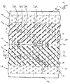
- Fig. 1 shows a section of a plastic sheet according to the invention in plan view.
- the plastic plate is made of a thermoplastic material, in particular PVC, PE, PP, PVDF and ECTFE.
- the thickness of the plastic plate is 1 to 5 mm, preferably 2 to 4 mm, so that they on the one hand sufficient strength, on the other hand, but also sufficient flexibility Bending has.
- the plate is 2 mm thick. It can be provided as a web product in different lengths.
- the plastic plate has, on the side 1A facing the medium, a region 1 with a structured surface, adjoining which are non-structured smooth regions 2 on both sides, which merge into smooth welding edges 3 on the upper and lower sides.
- the edges 3 of the surface structure which occupies the substantial part of the total surface of the plastic plate, is formed from a plurality of flow elements 4, which are arranged side by side in individual rows IV.
- the flow elements 4 are formed as elongated elevations, which terminate pointedly to the ends. They form narrow webs, which are integral with the plastic plate, the narrow webs have a height of 2 to 8 mm, preferably 3 to 7 mm, more preferably 4 to 6 mm. In the embodiment, the narrow webs have a height a of 5 mm approx.
- the webs have a length b of 20 to 140 mm, more preferably 40 to 120 mm, further preferably 60 to 100. In the embodiment, the narrow webs have a length of 85 mm. They preferably have a width c of 1 to 40 mm. In the embodiment, the width of the webs ca, 5 mm.
- the area 1 with the structured surface is subdivided into a left half 1 'and a right half 1 "
- the narrow webs 4 are mirror-inverted in the left and right half with respect to the longitudinal axis 5 of the plastic plate Longitudinal axis 5 of the plastic plate, which corresponds to the flow direction of the medium, an angle ⁇ of 30 to 60 °, preferably 50 to 45 °. In the embodiment, the angle is about 45 °.
- the longitudinal axes of each arranged in a row IV webs 4 lie on a common axis.
- the distance d of lying on the common axis 6 webs 4 is smaller than the length b of the webs.
- the distance e between the individual rows IV of the webs smaller than the length b of the webs, but larger than the distance d between the webs.
- the webs 4 arranged in the left and right half 1 ', 1 "of the plastic plate are aligned such that they point in the direction of flow 9.
- the webs each have an upstream flank 4A pointing in the flow direction 9 and a downstream flank 4B facing the flow direction. It is crucial that the flank 4A pointing in the direction of flow is steeper than the flank pointing counter to the direction of flow
- the flanks 4A of the webs pointing in the direction of flow close to the surface of the plastic plate at an angle of approx.
- the flanks 4B of the webs 4 pointing counter to the direction of flow enclose an angle of approximately 45 ° with the surface of the plastic plate 1.
- the flanks 4A pointing in the direction of flow terminate in a small radius at the base point, while the flanks 4A opposite to the flow direction facing edges 4B in egg ner sharp edge (Fig. 3).
- FIG. 1 the plastic plate 1, except in the region of the welding edges 3 projecting anchoring elements 10, which are integral with the plastic plate.
- the anchoring elements located only on the rear side of the plate are shown schematically in FIG. 1.
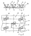
- the anchoring elements 10 are in each case designed as two wing elements 11, 12 which spread apart and which are connected to one another via a support web 13.
- the wing elements 11, 12 go over at the base in an arc 14 in the Kwiststoff plate steadily. This results in a comparatively wide connection surface of the wing elements with the plastic plate.
- the height of the support webs 13 is at least 70%, preferably at least 80% of the height of the wing elements.
- Each of an anchoring element 10 forming wing elements are offset from one another.
- the plastic plate is a coextruded plate having a sandwich structure with a first layer comprising the flow elements (4) and a second layer comprising the anchoring elements (9).
- the first and second layers are made of materials and with different mechanical and / or chemical and / or optical properties.
- the first layer with the flow elements 9 consists of a colored plastic material, while the second layer with the anchoring elements consists of a non-colored plastic material. Therefore, it is possible to optically monitor the wear of the first layer in contact with the medium in a simple manner. So can be recognized by the color, whether the first layer is removed. This monitoring can be done with a camera.
- the plastic material of the first layer is more resistant to abrasion than the material of the second layer
- the individual plastic sheets are inserted into the formwork of the concrete pipe and welded together at their Sch Strukturrändem 3 to a tubular lining-concreting the plastic plates are connected by means of anchoring elements 10 positively to the concrete component.
- anchoring increased long-term strength is achieved.
- the flow elements 4 on the inside of the tubular lining increase the entrainment of the entrained in the medium particles and thus prevent the formation of deposits on the tube inside.
- the decisive advantage of the plastic sheet according to the invention is that concrete components can be cost-effectively lined in a simple manner, with a high long-term strength and towing effect being achieved. It It should be noted that the increase in the drag effect with the preferred design of the flow elements of its own inventive importance. Because it would also be possible in principle to attach the plastic plate in a different way than with the anchoring elements on the concrete component. Then, although the increased long-term strength would not be given, but the benefits of the increased drag effect would be effective.
Landscapes
- Engineering & Computer Science (AREA)
- General Engineering & Computer Science (AREA)
- Mechanical Engineering (AREA)
- Physics & Mathematics (AREA)
- Fluid Mechanics (AREA)
- Laminated Bodies (AREA)
- Lining And Supports For Tunnels (AREA)
- Sewage (AREA)
- Finishing Walls (AREA)
- Protection Of Pipes Against Damage, Friction, And Corrosion (AREA)
- Road Paving Structures (AREA)
- Aftertreatments Of Artificial And Natural Stones (AREA)
- Forms Removed On Construction Sites Or Auxiliary Members Thereof (AREA)
- Road Signs Or Road Markings (AREA)
Abstract
Description
- Die Erfindung bezieht sich auf eine Kunststoffplatte zum Auskleiden von Betonbauteilen, insbesondere Betonrohren, die von einem fließfähigen Medium durchströmt werden. Darüber hinaus betrifft die Erfindung eine Anordnung aus Kunststoffplatten zum Auskleiden von Betonbauteilen.
- Zur Auskleidung von Betonbehältern, die flüssige oder gasförmige Chemikalien enthalten, sind Kunststoffplatten bekannt, die den Beton vor den Chemikalien schützen. Derartige Kunststoffplatten werden vielfach mit dem Betonbauteil verklebt. Da die glatte Oberfläche der Kunststoffplatten aber keine feste mechanische Verbindung mit dem Beton eingeht, besteht die Gefahr, dass sich die Kunststoffplatten im Laufe der Zeit lösen.
- Aus der
WO 01/57340 A1 - Die aus der
WO 01/57340 A1 - Um dem Medium einen möglichst geringen Widerstand entgegenzusetzen, wird grundsätzlich angestrebt, die Oberfläche der Auskleidung möglichst glatt auszubilden. Nachteilig ist jedoch, dass sich insbesondere im Bereich von Rohrkrümmungen oder -abzweigungen sowie Reduzierungen oder Erweiterungen des Rohrquerschnitts an der Rohrinnenwand im Laufe der Zeit Festkörper ablagern können, die in dem Medium enthalten sind. Insbesondere bei Mischkanalisationen, die extremen Schwankungen des Abflussvolumens ausgesetzt sind, zählen die Ablagerungen zu den typischen Schadensbildern.
- Aus der
EP 1 194 712 B1 xst eine Rohrleitung bekannt, deren Wandung eine strukturierte Oberfläche aufweist, die aus einer Vielzahl von quaderförmigen oder pyrarnidenfo-rraigen Erhebungen besteht. Es hat sich gezeigt, dass sich bei der strukturierten Oberfläche eine Grenzschicht an der Rohrwandung ausbildet, die bewirkt, dass die Fähigkeit, in dem Medium mitgeführte Partikel mitzureißen, erhöht wird. Entsprechend wird die Neigung, dass Partikel an der Wandung haften, stark reduziert. Dieser Effekt wird allgemein als Erhöhung der Schleppwirkung der im Medium mitgeführten Partikel bezeichnet. - Die
EP 1 194 712 B1 schlägt vor, entweder die Wandung des Rohrs mit der strukturierten Oberfläche zu versehen oder in das Rohr einen rohrförmigen strukturierten Folien- oder Platteneinsatz einzuziehen, der mit dem Rohr verklebt wird. - Der Erfindung liegt die Aufgabe zugrunde, von einem fließfähigen Medium durchströmte Betonbauteile unterschiedlicher Ausbildung auf einfache Weise derart auszukleiden, dass die Betonbauteile vor aggressiven Medien geschützt sind, ohne dass die Gefahr der Ablagerung von in den Medien enthaltenen Partikeln an der Wandung der Betonbauteile besteht.
- Die Lösung dieser Aufgabe erfolgt erfindungsgemäß mit den Merkmalen des Patentanspruchs 1 bzw. 22.
- Zur Auskleidung der Betonbauteile findet erfindungsgemäl3 nicht ein rohrfönniger Folien- oder Platteneinsatz Verwendung, sondern Kunststoffplatten, die zu einem das Bauteil auskleidenden Körper miteinander verbunden werden. Da die Kunststoffpla.tten eine ausreichende Flexibilität haben, besteht die Möglichkeit, nicht nur rechteckfi3rmige, sondern auch rohrförmige Betonbauteile auszukleiden, Nach dem Einlegen der Kunststoffplatten in das Betonbauteil werden die Platten vorzugsweise miteinander verschweißt.
- Die erfindungsgemäße Kunststoffplatte weist an der dem Medium zugewandten Seite eine Vielzahl von nebeneinander angeordneten Strömungselementen auf, die als erhabene Strukturen mit einer in Flussrichtung weisenden stromaufwärtigen Flanke und einer entgegen der Flussrichtung weisenden stromabwärtigen Flanke ausgebildet sind, wobei die zwischen den Strömungselementen liegenden Oberflächenbereiche glatt sind. Dadurch wird die Schleppwirkung der im Medium mitgeführten Partikel selbst bei niedrigen Strömungsgeschwindigkeiten und diskontinuierlichem Betrieb erhöht, An der dem Medium abgewandten Seite weist die Kunststoffplatte eine Vielzahl von Verankerungselementen auf, so dass die Kunststoffplatte mit dem Betonbauteil formschlüssig verbindbar ist.
- In zahlreichen Versuchen hat sich gezeigt, dass die Schleppwirkung der im Medium mitgeiuhrten Partikel erhöht werden kann, wenn die erhabenen Strukturen dem fließfähigen Medium einen gewissen Widerstand entgegensetzen. Dies wird dadurch erreicht, dass die erhabenen Strukturen mit einer in Flussrichtung weisenden stromaufwärtigen Flanke und der entgegen der Flussrichtung weisenden stromabwärtigen Flanke ausgebildet sind. Dieser Effekt tritt insbesondere dann auf, wenn die in Flussrichtung weisenden Flanken der Strömungselemente steiler als die entgegen der Strömungsrichtung weisenden Flanken sind. Damit weisen die Strömungslemente einen keilförmigen Querschnitt auf Es hat sich als vorteilhaft erwiesen, wenn die in Flussrichtung weisenden stromaufwärtigen Flanken der Stromungselemente mit den glatten Oberflächenbereichen der Kunststoffplatte einen Winkel von 70 bis 90°, vorzugsweise 80 bis 90°, insbesondere ca. 90° einschließen. Die entgegen der Flussrichtung weisenden stromabwärtigen Flanken der Strömungselemente schließen mit den glatten Oberflächenbereichen der Kunststoffplatte vorzugsweise einen Winkel von 30 bis 60°, weiterhin vorzugsweise 40 bis 50°, insbesondere ca. 45° ein.
- Bei einer bevorzugten Ausführungsform ist die Kunststoffplatte in zwei Hälften aufgeteilt, wobei die Strömungselemente auf den beiden Hälften spiegelbildlich angeordnet sind. Vorzugsweise sind die Strömungselemente in einzelnen Reihen jeweils auf einer gemeinsamen Achse nebeneinanderliegend angeordnet. Dabei hat sich als vorteilhaft erwiesen, dass der Abstand zwischen den Strömungselementen auf einer Reihe kleiner als die Länge der Strömungselemente ist.
- Bei einer weiteren bevorzugten Ausfuhrungsfbnn sind die Strömungselemente als langgestreckte Erhebungen ausgebildet. Unter langgestreckten Erhebungen sind alle Erhebungen zu verstehen, die in Längsrichtung eine Ausdehnung haben, die ein Vielfaches der Ausdehnung in Querrichtung ist. Vorzugsweise laufen die als langgestreckte Erhebungen ausgebildeten Strömungselemente zu den Enden spitz aus. Es ist aber auch möglich, dass die Strömungselemente an den Enden abgerundet sind.
- In den Versuchen hat sich gezeigt, dass sich eine besonders hohe Schleppwirkung erzielen lässt, wenn die Längsachsen der als langgestreckte Erhebungen ausgebildeten Strömungselemente mit der Längsrichtung der Kunststoffplatten, die in Flussrichtung des fließfähigen Medium verläuft, einen Winkel von 30 bis 60°, weiterhin vorzugsweise 40 bis 50°, insbesondere ca, 45° einschließen. Vorzugsweise sind die langgestreckten Erhebungen in einzelnen Reihen jeweils auf einer gemeinsamen Achse angeordnet, wobei die Kunststoffplatte vorzugsweise in zwei Hälften aufgeteilt ist, auf denen die Strömungselemente spiegelbildlich angeordnet sind. Damit wird eine rippenartige Oberftächenstruktur mit schmalen Stegen geschaffen, wobei die Achsen, auf denen die langgestreckten Erhebungen liegen, schräg zur Flussrichtung verlaufen.
- Weitere bevorzugte Ausgestaltungen der Strömungselemente und der Verankerungselemente sind Gegenstand der Unteransprüche.
- Im folgenden wird ein Ausfüluungsbeispiel der Erfindung unter Bezugnahme auf die Zeichnungen im einzelnen erläutert.
- Es zeigen:
- Fig. 1
- einen Ausschnitt einer erfindungsgemäßen Kunststoffplatte in der Draufsicht,
- Fig. 2
- einen Schnitt durch die Kunststoffplatte von Fig. 1 entlang der Linie A-A in vergrößerter Darsstellung,
- Fig. 3
- einen Schnitt durch die Kunststoffplatte von Fig. 1 entlang der Linie B-B in vergrößerter Darstellung,
- Fig. 4
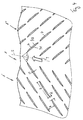
- einen vergrößerten Ausschnitt der Kunststoffplatte von Fig. 1 in der Draufsicht,
- Fig. 5
- eine Seitenansicht von nebeneinanderliegenden Verankerungselementen der Kunststoffplatte von Fig, 1 in vergrößerter Darstellung und
- Fig. 6
- einen vergrößerten Ausschnitt der Kunststoffplatte von Fig. 1 in der Unteransicht.
- Fig. 1 zeigt einen Ausschnitt einer erfindungsgemäßen Kunststoffplatte in der Draufsicht. Die Kunststoffplatte besteht aus einem thermoplastischen WerkstofF, insbesondere PVC, PE, PP, PVDF und ECTFE. Die Stärke der Kunststoffplatte beträgt 1 bis 5 mm, vorzugsweise 2 bis 4 nun, so dass sie einerseits eine ausreichende Festigkeit, andererseits aber auch eine ausreichende Flexibilität zum Biegen aufweist. Bei dem Ausführungsbeispiel ist die Platte 2 mm stark. Sie kann als Bahnenware in unterschiedlichen Längen bereitgestellt werden.
- Die Kunststoffplatte weist an der dem Medium zugewandten Seite 1A einen Bereich 1 mit einer strukturierten Oberfläche auf, an den sich zu beiden Seiten nicht strukturierte glatte Bereiche 2 anschließen, die in an Ober- und Unterseite glatte Schweißränder 3 übergehen. Die Ränder 3 der Die Oberflächenstruktur, die den wesentlichen Teil der Gesamtoberfläche der Kunststoffplatte einnimmt, wird aus einer Vielzahl von Strömungselementen 4 gebildet, die in einzelnen Reihen IV jeweils nebeneinander angeordnet sind.
- Die Strömungselemente 4 sind als langgestreckte Erhebungen ausgebildet, die zu den Enden spitz auslaufen. Sie bilden schmale Stege, die mit der Kunststoffplatte einstückig sind, Die schmalen Stege haben eine Höhe von 2 bis 8 mm, vorzugsweise 3 bis 7 mm, weiterhin vorzugsweise 4 bis 6 mm. Bei dem Ausführungsbeispiel haben die schmalen Stege eine Höhe a von 5 ca. mm. Die Stege haben eine Länge b von 20 bis 140 mm, weiterhin vorzugsweise 40 bis 120 mm, weiterhin vorzugsweise 60 bis 100. Bei dem Ausführungsbeispiel haben die schmale Stege eine Länge von 85 mm. Sie haben vorzugsweise eine Breite c von 1 bis 40 mm. Bei dem Ausführungsbeispiel ist die Breite der Stege ca, 5 mm.
- Der Bereich 1 mit der strukturierten Oberfläche unterteilt sich in eine linke Hälfte 1' und eine rechte Hälfte 1". Die schmalen Stege 4 sind in der linken und rechten Hälfte bezüglich der Längsachse 5 der Kunststoffplatte spiegelbildlich ausgerichtet. Die Längsachsen 6 aller Stege schließen mit der Längsachse 5 der Kunststoffplatte, die der Flussrichtung des Medium entspricht, einen Winkel α von 30 bis 60°, vorzugsweise 50 bis 45 ° ein. Bei dem Ausführungsbeispiel ist der Winkel ca. 45°.
- Die Längsachsen der jeweils in einer Reihe IV angeordneten Stege 4 liegen auf einer gemeinsamen Achse. Dabei ist der Abstand d der auf der gemeinsamen Achse 6 liegenden Stege 4 kleiner als die Länge b der Stege. Auch ist der Abstand e zwischen den einzelnen Reihen IV der Stege kleiner als die Länge b der Stege, aber größer als der Abstand d zwischen den Stegen.
- Die in der linken und rechten Hälfte 1', 1" der Kunststoffplatte angeordneten Stege 4 sind derart ausgerichtet, dass sie in Flussrichtung 9 zeigen. Die Stege haben jeweils eine in Flussrichtung 9 weisende stromaufwärtige Flanke 4A und eine entgegen der Flussrichtung weisende stromababwärtige Flanke 4B. Entscheidend ist, dass die in Flussrichtung weisende Flanke 4A steiler als die entgegen der Flussrichtung weisende Flanke ist. Insofern haben die Stege einen keilförmigen Querschnitt. Bei dem Ausführungsbeispiel schließen die in Flussrichtnng weisenden Flanken 4A der Stege mit der Oberfläche der Kunststoffplatte einen Winkel von ca. 90° ein. Die entgegen der Flussrichtung weisenden Flanken 4B der Stege 4 schließen mit der Oberfläche der Kunststoffplatte 1 bei dem Ausführungsbeispiel einen Winkel von ca. 45°ein. Die in Strömungsrichtung weisenden Flanken 4A laufen am Fußpunkt in einem kleinen Radius aus, während die entgegen der Strömungsrichtung weisenden Flanken 4B in einer scharfen Kante enden (Fig. 3).
- Nachfolgend wird unter Bezugnahme auf die Fig. 5 und 6 die dem Betonbauteil zugewandte Rückseite 1 B der Kunststoß'plstte beschrieben. An der Rückseite weist die Kunststoffplatte 1 mit Ausnahme im Bereich der Schweißränder 3 vorspringende Verankerungselemente 10 auf, die mit der Kunststoffplatte einstückig sind. Die nur an der Rückseite der Platte befindlichen Verankerungselemente sind in Fig. 1 andeutungsweise dargestellt Die Verankerungselemente 10 sind jeweils als zwei sich verspreizende Flügelelemente 11, 12 ausgebildet, die über einen Stützsteg 13 miteinander verbunden sind. Die Flügelelemente 11, 12 gehen am Fußpunkt in einem Bogen 14 in die Kwiststoff-platte stetig über. Hierdurch ergibt sich ein vergleichsweise breite Verbindungsfläche der Flügelelemente mit der Kunststoffplatte. Die Höhe der Stützstege 13 beträgt mindestens 70%, vorzugsweise mindestens 80% der Höhe der Flügelelemente. Die jeweils ein Verankerungselement 10 bildenden Flügelelemente sind versetzt zueinander angeordnet.
- Die Ausbildung der Verankerungselemente 10 an der Rückseite der Kunststoffplatte 1 ist im einzelnen in der
WO 01/57340 A1 - Die Kunststoffplatte ist eine koextrudierte Platte, die eine Sandwichstruktur mit einer die Strömuagselemente (4) umfassenden ersten Schicht und einer die Verankerungselemente (9) umfassenden zweiten Schicht aufweist. Die erste und zweite Schicht bestehen aus Materialien und mit unteshiedlichen mechanischen und/oder chemischen und/oder optischen Eigenschaften. Die erste Schicht mit den Strömungselementen 9 besteht aus einem eingefärbten Kunststoffmaterial, während die zweite Schicht mit den Verankerungselementen aus einem nicht eingefärbten Kunststoffmaterial besteht. Daher ist es möglich, die Abnutzung der mit dem Medium in Kontakt tretenden ersten Schicht auf einfache Weise optisch zu überwachen. So kann anhand der Farbe erkannt werden, ob die erste Schicht abgetragen ist. Diese Überwachung kann mit einer Kamera erfolgen. Weiterhin ist das Kunststoffmaterial der ersten Schicht abrasionsfester als das Material der zweiten Schicht
- Zum Auskleiden von Betonbauteilen, insbesondere Betonrohren, werden die einzelnen Kunststoffplatten in die Schalung des Betonrohrs eingelegt und an ihren Schweißrändem 3 zu einer rohrförmigen Auskleidung miteinander verschweißt-Beim Betonieren werden die Kunststoffplatten mittels der Verankerungselemente 10 formschlüssig mit dem Betonbauteil verbunden. Durch diese Verankerung wird eine erhöhte Langzeitfestigkeit erreicht. Die Strömungselemente 4 an der Innenseite der rohrförmigen Auskleidung erhöhen die Schleppwirkung der in dem Medium mitgeführten Partikel und verhindern somit die Bildung von Ablagerungen an der Rohrinnenseite.
- Der entscheidende Vorteil der erfindungsgemäßen Kunststoffplatte liegt darin, dass auf einfache Weise Betonbauteile kostengünstig ausgekleidet werden können, wobei eine hohe Langzeitfestigkeit und Schleppwirkung erzielt wird. Es sei bemerkt, dass die Erhöhung der Schleppwirkung mit der bevorzugten Ausbildung der Strömungselemente von eigener erfinderischer Bedeutung ist. Denn es wäre grundsätzlich auch möglich, die Kunststoffplatte auf eine andere Weise als mit den Verankerungselementen an dem Betonbauteil zu befestigen. Dann wäre zwar die erhöhte Langzeitfestigkeit nicht gegeben, aber die Vorteile der erhöhten Schleppwirkung kämen zum Tragen.
Claims (22)
- KunststoffpIatte zum Auskleiden von Betonbauteilen, die von einem fließiahigen Medium durchströmt werden, wobei die der Wandung des Betonbauteils zugewandte Seite (1A) der Kunststoffplatte eine Vielzahl von Verankerungselementen (10) aufweist, so dass die Kunststoffplatte mit dem Betonbauteil formschlüssig verbindbar ist,
dadurch gekennzeichnet,
dass die dem Medium zugewandte Seite (1 B) der Kunststoffplatte eine Vielzahl von nebeneinander angeordneten Strömungselementen (4) aufweist, die als erhabene Strukturen mit einer in Flussrichtung (9) weisenden stromaufwärtigen Flanke (4A) und einer entgegen der Flussrichtung weisenden stromabwärtigen Flanke (4B) ausgebildet sind, wobei die zwischen den Strömungselementen liegenden Oberflächenbereiche der Kunststoffplatte glatt sind, so dass sich die Schleppwirkung der im Medium mitgeführten Partikel erhöht. - Kunststoffplatte nach Anspruch 1,
dadurch gekennzeichnet, dass die in Flussrichtung (9) weisenden stromaufwärtigen Flanken (4A) der Strömungselemente (4) steiler als die entgegen der Strömungsrichtung weisenden stromabwärtigen Flanken (4B) sind. - KunststoSplatte nach Anspruch 1 oder 2,
dadurch gekennzeichnet, dass die in Flussrichtung (9) weisenden stromaufwärtigen Flanken (4A) der Strvmungselemente (4) mit den glatten Oberflächenbereichen der Kunststoffplatte einen Winkel von 70 bis 90°, vorzugsweise 80 bis 90°, insbesondere ca. 90° einschließen, - Kunststoffplatte nach einem der Ansprüche 1 bis 3,
dadurch gekennzeichnet, dass die entgegen der Flussrichtung (9) weisenden stromabwärtigen Flanken (4B) der Strömungselemente (4) mit den glatten Oberflächenbereichen der Kunststoffplatte einen Winkel von 30 bis 60°, vorzugsweise 40 bis 50°, insbesondere ca. 45° einschließen. - Kunststoffplatte nach einem der Ansprüche 1 bis 4,
dadurch gekennzeichnet, dass die Kunststoffplatte in zwei Hälften (1, 1') aufgeteilt ist, wobei die Strömungselemente(4) auf den beiden Hälften spiegelbildlich angeordnet sind, - Kunststoffplatte nach einem der Ansprüche 1 bis 5,
dadurch gekennzeichnet, dass die Strömungselemente (4) in einzelnen Reihen (IV) jeweils auf einer gemeinsamen Achse (6) nebeneinanderliegend angeordnet sind. - Kunststoffplatte nach einem der Ansprüche 1 bis 6,
dadurch gekennzeichnet, dass der Abstand (d) zwischen den Strömungselementen (4) auf einer Reihe (IV) kleiner als die Länge (b) der Strömungselemente ist. - Kunststoffplatte nach einem der Ansprüche 1 bis 7,
dadurch gekennzeichnet, dass die gemeinsamen Achsen (6), auf denen die Stromungselemente (4) angeordnet sind, mit der Längsachse (5) der Kunststoffplatte einen Winkel von 30 bis 60°, vorzugsweise 40 bis 50°, insbesondere ca. 45° einschließen. - Kunststoffplatte nach einem der Ansprüche 1 bis 8,
dadurch gekennzeichnet, dass die Strömungselemente (4) als langgestreckte Erhebungen ausgebildet sind. - Kunststoffplatte nach Anspruch 9,
dadurch gekennzeichnet, dass die Längsachsen (6) der als langgestreckte Erhebungen ausgebildeten Strömungselemente (4) mit der Längsachse (5) der Kunststoffplatte einen Winkel von 30 bis 60°, vorzugsweise 40 bis 50°, insbesondere ca. 45° einschließen. - Kunststoffplatte nach Anspruch 9 oder 10,
dadurch gekennzeichnet, dass die als langgestreckte Erhebungen ausgebildeten Strömungselemente (4) zu den Enden spitz auslaufen. - Kunststoffplatte nach einem der Ansprüche 9 bis 11,
dadurch gekennzeichnet, dass die als langgestreckte Erhebungen ausgebildeten Strümungselemente (4) eine Höhe (a) von 2 bis 8 mm, vorzugsweise 3 bis 7 mm, weiterhin vorzugsweise 4 bis 6 mm, insbesondere ca. 5 mm haben. - Kunststoffplatte nach einem der Ansprüche 9 bis 12,
dadurch gekennzeichnet, dass die als langgestreckte Erhebungen ausgebildeten Strömungselemente (4) eine Länge (b) von 20 bis 140 mm, vorzugsweise 40 bis 120 mm, weiterhin vorzugsweise 60 bis 100 mm, insbesondere ca. 80 mm haben. - Kunststoffplatte nach einem der Ansprüche 9 bis 13,
dadurch gekennzeichnet, dass die als langgestreckte Erhebungen ausgebildeten Strömungselemente (4) eine Breite von 1 bis 40 mm, vorzugsweise 1 bis 10 mm, insbesondere ca. 5 mm haben. - Kunststoffplatte nach einem der Ansprüche 1 bis 14,
dadurch gekennzeichnet, dass die Verankerungselemente (10) als sich verspreizende Flügelelemente (11, 12) ausgebildet sind, die in ihrem Fußbereich Stützstege (13) aufweisen. - Kunststoffplatte nach Anspruch 15
dadurch gekennzeichnet, dass die Höhe der Stützstege (13) mindestens 70%, vorzugsweise mindestens 80% der Höhe der Flügelelemente (11, 12) beträgt. - Kunststoffplatte nach Anspruch 15 oder 16,
dadurch gekennzeichnet, dass die Flügelelemente (11, 12) in ihrem Fußbereich bogenförmige Übergänge (14) aufweisen. - Kunststoffplatte nach einem der Ansprüche 15 bis 17,
dadurch gekennzeichnet, dass jeweils zwei Flügelelemente (11, 12) versetzt zueinander angeordnet und über mindestens einen Stützsteg (13) miteinander verbunden sind. - Kunststoffplatte nach einem der Ansprüche 1 bis 18,
dadurch gekennzeichnet, dass die Kunststoffplatte Schweißränder (3) aufweist, an denen die dem Medium zu- und abgewandten Seiten (1A, 1B) der Kunststoffplatte glatt sind. - Kunststoffplatte nach einem der Ansprüche 1 bis 19, dadurch gekennzeichnet, dass die Kunststoffplatte eine Sandwichstruktur mit einer die Strömungselemente (4) umfassenden ersten Schicht und einer die Verankerungselemente (9) umfassenden zweiten Schicht aufweist.
- Kunststoffplatte nach Anspruch 20, dadurch gekennzeichnet, dass die erste und zweite Schicht aus Materialien mit unterschiedlichen mechanischen und/oder chemischen und/oder optischen Eigenschaften bestehen.
- Anordnung aus Kunststoffplatten nach einem der Ansprüche 1 bis 21,
wobei die Kunststoffplatten zu einem das Bauteil auskleidenden Körper miteinander verbunden sind.
Priority Applications (15)
| Application Number | Priority Date | Filing Date | Title |
|---|---|---|---|
| EP05008845A EP1715196B1 (de) | 2005-04-22 | 2005-04-22 | Kunststoffplatte zum Auskleiden von Betonbauteilen |
| ES05008845T ES2377651T3 (es) | 2005-04-22 | 2005-04-22 | Placa de plástico para revestir módulos de hormigón |
| DK05008845.9T DK1715196T3 (da) | 2005-04-22 | 2005-04-22 | Kunststofplade til beklædning af betonkonstruktionselementer |
| PL05008845T PL1715196T3 (pl) | 2005-04-22 | 2005-04-22 | Płyta z tworzywa sztucznego do wykładania betonowych elementów konstrukcyjnych |
| PT05008845T PT1715196E (pt) | 2005-04-22 | 2005-04-22 | Painel de material sintético para o revestimento de componentes de betão |
| SI200531477T SI1715196T1 (sl) | 2005-04-22 | 2005-04-22 | Plošča iz umetnega materiala za oblaganje betonskih gradbenih elementov |
| AT05008845T ATE535718T1 (de) | 2005-04-22 | 2005-04-22 | Kunststoffplatte zum auskleiden von betonbauteilen |
| BRPI0610504-1A BRPI0610504A2 (pt) | 2005-04-22 | 2006-04-22 | chapa de plástico para forrar componentes de concreto |
| PCT/EP2006/003728 WO2006111418A2 (de) | 2005-04-22 | 2006-04-22 | Kunststoffplatte zum auskleiden von betonbauteilen |
| KR1020077017464A KR101322766B1 (ko) | 2005-04-22 | 2006-04-22 | 콘크리트 요소를 라이닝하기 위한 플라스틱 플레이트 |
| JP2008507020A JP4832509B2 (ja) | 2005-04-22 | 2006-04-22 | コンクリート部材のライニング用プラスチック板及びその配置 |
| CNA2006800050201A CN101155998A (zh) | 2005-04-22 | 2006-04-22 | 用作混凝土构件衬里的塑料板 |
| CA2591910A CA2591910C (en) | 2005-04-22 | 2006-04-22 | Plastic plate for lining concrete components |
| AU2006237223A AU2006237223B2 (en) | 2005-04-22 | 2006-04-22 | Plastic plate for lining concrete components |
| ZA200704706A ZA200704706B (en) | 2005-04-22 | 2007-06-08 | Plastic plate for lining concrete components |
Applications Claiming Priority (1)
| Application Number | Priority Date | Filing Date | Title |
|---|---|---|---|
| EP05008845A EP1715196B1 (de) | 2005-04-22 | 2005-04-22 | Kunststoffplatte zum Auskleiden von Betonbauteilen |
Publications (2)
| Publication Number | Publication Date |
|---|---|
| EP1715196A1 true EP1715196A1 (de) | 2006-10-25 |
| EP1715196B1 EP1715196B1 (de) | 2011-11-30 |
Family
ID=34935590
Family Applications (1)
| Application Number | Title | Priority Date | Filing Date |
|---|---|---|---|
| EP05008845A Expired - Lifetime EP1715196B1 (de) | 2005-04-22 | 2005-04-22 | Kunststoffplatte zum Auskleiden von Betonbauteilen |
Country Status (15)
| Country | Link |
|---|---|
| EP (1) | EP1715196B1 (de) |
| JP (1) | JP4832509B2 (de) |
| KR (1) | KR101322766B1 (de) |
| CN (1) | CN101155998A (de) |
| AT (1) | ATE535718T1 (de) |
| AU (1) | AU2006237223B2 (de) |
| BR (1) | BRPI0610504A2 (de) |
| CA (1) | CA2591910C (de) |
| DK (1) | DK1715196T3 (de) |
| ES (1) | ES2377651T3 (de) |
| PL (1) | PL1715196T3 (de) |
| PT (1) | PT1715196E (de) |
| SI (1) | SI1715196T1 (de) |
| WO (1) | WO2006111418A2 (de) |
| ZA (1) | ZA200704706B (de) |
Cited By (1)
| Publication number | Priority date | Publication date | Assignee | Title |
|---|---|---|---|---|
| BE1026591B1 (nl) * | 2018-09-06 | 2020-04-06 | M H C Nv | Betonnen bouwelement |
Families Citing this family (3)
| Publication number | Priority date | Publication date | Assignee | Title |
|---|---|---|---|---|
| CN104370010B (zh) * | 2014-09-11 | 2017-01-18 | 韦琪琪 | 塑混结构容器 |
| CN104261004A (zh) * | 2014-09-11 | 2015-01-07 | 韦琪琪 | 一种储放腐蚀性液体的方法 |
| CN105951970A (zh) * | 2016-04-28 | 2016-09-21 | 成都津泽环保工程有限责任公司 | 一种混凝土管道用衬垫结构及混凝土管道 |
Citations (7)
| Publication number | Priority date | Publication date | Assignee | Title |
|---|---|---|---|---|
| US4004615A (en) * | 1974-02-04 | 1977-01-25 | Klockner-Humboldt-Deutz Aktiengesellschaft | Parts subject to wear in separators, cyclones, pipelines and similar apparatus |
| US4280870A (en) * | 1978-05-30 | 1981-07-28 | Escher Wyss Gmbh | Pulp feed for a papermaking machine |
| US4506865A (en) * | 1983-03-11 | 1985-03-26 | Bragin Boris F | Valve housing |
| US4986496A (en) * | 1985-05-31 | 1991-01-22 | Minnesota Mining And Manufacturing | Drag reduction article |
| US5070937A (en) * | 1991-02-21 | 1991-12-10 | American Standard Inc. | Internally enhanced heat transfer tube |
| WO2001057340A1 (de) | 2000-01-31 | 2001-08-09 | Alois Gruber Gmbh | Kunststoffplatte, insbesondere zum auskleiden von betonbauteilen |
| EP1194712A1 (de) * | 1999-07-14 | 2002-04-10 | FITR Gesellschaft für Innovation im Tief- und Rohrleitungsbau Weimar m.b.H. | Rohrleitungen und leitungselemente zum transportieren fliessfähiger medien |
-
2005
- 2005-04-22 SI SI200531477T patent/SI1715196T1/sl unknown
- 2005-04-22 DK DK05008845.9T patent/DK1715196T3/da active
- 2005-04-22 PL PL05008845T patent/PL1715196T3/pl unknown
- 2005-04-22 AT AT05008845T patent/ATE535718T1/de active
- 2005-04-22 ES ES05008845T patent/ES2377651T3/es not_active Expired - Lifetime
- 2005-04-22 EP EP05008845A patent/EP1715196B1/de not_active Expired - Lifetime
- 2005-04-22 PT PT05008845T patent/PT1715196E/pt unknown
-
2006
- 2006-04-22 WO PCT/EP2006/003728 patent/WO2006111418A2/de not_active Ceased
- 2006-04-22 BR BRPI0610504-1A patent/BRPI0610504A2/pt not_active Application Discontinuation
- 2006-04-22 CN CNA2006800050201A patent/CN101155998A/zh active Pending
- 2006-04-22 KR KR1020077017464A patent/KR101322766B1/ko not_active Expired - Fee Related
- 2006-04-22 AU AU2006237223A patent/AU2006237223B2/en not_active Ceased
- 2006-04-22 JP JP2008507020A patent/JP4832509B2/ja not_active Expired - Fee Related
- 2006-04-22 CA CA2591910A patent/CA2591910C/en not_active Expired - Fee Related
-
2007
- 2007-06-08 ZA ZA200704706A patent/ZA200704706B/xx unknown
Patent Citations (8)
| Publication number | Priority date | Publication date | Assignee | Title |
|---|---|---|---|---|
| US4004615A (en) * | 1974-02-04 | 1977-01-25 | Klockner-Humboldt-Deutz Aktiengesellschaft | Parts subject to wear in separators, cyclones, pipelines and similar apparatus |
| US4280870A (en) * | 1978-05-30 | 1981-07-28 | Escher Wyss Gmbh | Pulp feed for a papermaking machine |
| US4506865A (en) * | 1983-03-11 | 1985-03-26 | Bragin Boris F | Valve housing |
| US4986496A (en) * | 1985-05-31 | 1991-01-22 | Minnesota Mining And Manufacturing | Drag reduction article |
| US5070937A (en) * | 1991-02-21 | 1991-12-10 | American Standard Inc. | Internally enhanced heat transfer tube |
| EP1194712A1 (de) * | 1999-07-14 | 2002-04-10 | FITR Gesellschaft für Innovation im Tief- und Rohrleitungsbau Weimar m.b.H. | Rohrleitungen und leitungselemente zum transportieren fliessfähiger medien |
| EP1194712B1 (de) | 1999-07-14 | 2004-09-29 | FITR Gesellschaft für Innovation im Tief- und Rohrleitungsbau Weimar m.b.H. | Rohrleitungen und leitungselemente zum transportieren fliessfähiger medien |
| WO2001057340A1 (de) | 2000-01-31 | 2001-08-09 | Alois Gruber Gmbh | Kunststoffplatte, insbesondere zum auskleiden von betonbauteilen |
Cited By (1)
| Publication number | Priority date | Publication date | Assignee | Title |
|---|---|---|---|---|
| BE1026591B1 (nl) * | 2018-09-06 | 2020-04-06 | M H C Nv | Betonnen bouwelement |
Also Published As
| Publication number | Publication date |
|---|---|
| JP4832509B2 (ja) | 2011-12-07 |
| ES2377651T3 (es) | 2012-03-29 |
| AU2006237223B2 (en) | 2012-02-16 |
| WO2006111418A2 (de) | 2006-10-26 |
| ATE535718T1 (de) | 2011-12-15 |
| KR101322766B1 (ko) | 2013-10-29 |
| DK1715196T3 (da) | 2012-03-05 |
| ZA200704706B (en) | 2009-08-26 |
| CA2591910A1 (en) | 2006-10-26 |
| WO2006111418A8 (de) | 2007-08-02 |
| CA2591910C (en) | 2014-04-15 |
| EP1715196B1 (de) | 2011-11-30 |
| KR20080020978A (ko) | 2008-03-06 |
| BRPI0610504A2 (pt) | 2012-01-10 |
| SI1715196T1 (sl) | 2012-04-30 |
| JP2008537077A (ja) | 2008-09-11 |
| PL1715196T3 (pl) | 2012-07-31 |
| CN101155998A (zh) | 2008-04-02 |
| AU2006237223A1 (en) | 2006-10-26 |
| WO2006111418A3 (de) | 2006-12-28 |
| PT1715196E (pt) | 2012-01-17 |
Similar Documents
| Publication | Publication Date | Title |
|---|---|---|
| DE2224320C2 (de) | Ausgabekopf für Bewässerungs- oder Berieselungsanlagen | |
| DE2633752C3 (de) | Erddrain | |
| DE69614402T2 (de) | Plattenwärmetauscher | |
| EP2335795B1 (de) | Förderband-Filtereinrichtung | |
| DE1930715A1 (de) | Gasfiltereinsatz | |
| DE2815628A1 (de) | Integrales tropfenbewaesserungssystem | |
| DE2030618B2 (de) | Schrägklärer | |
| DE3850990T2 (de) | Filterelement. | |
| DE1551430A1 (de) | Plattenwaermetauscher | |
| DE1634063B1 (de) | Draenrohr aus Kunststoff mit in axialer Richtung glatter Rohrinnenwand und ring- oder schraubengangfoermig angeordneten Verstaerkungsrippen an der Rohraussenwandung | |
| EP0553180B1 (de) | Adsorptionsmittel-, insbesondere wanderbettreaktor | |
| DE60006528T2 (de) | Filterunterdrainagesystem | |
| EP1165905A1 (de) | Kunststoffplatte, insbesondere zum auskleiden von betonbauteilen | |
| EP1715196B1 (de) | Kunststoffplatte zum Auskleiden von Betonbauteilen | |
| DE2844523A1 (de) | Bewaesserungseinrichtung | |
| DE2610691B2 (de) | Vorrichtung zum Führen der Stoffsuspension in einem Stoffauflauf einer Papiermaschine | |
| DE102011050805A1 (de) | Filtriervorrichtung für hochviskose Fluide | |
| DE2726709C2 (de) | Stoffauflaufvorrichtung einer Papiermaschine | |
| DE102017101680A1 (de) | Hydrofoil für ein Wasserfahrzeug | |
| DE19945009C2 (de) | Rohrleitungselement für eine Rohrleitung zum Transportieren fließfähiger Medien | |
| DE8812493U1 (de) | Schlitzdüse | |
| DE102012216146A1 (de) | Wärmeübertragungseinrichtung, Wärmeübertrager sowie Verfahren zur Übertragung von Wärme von einem ersten Fluid auf ein zweites Fluid | |
| DE102017004671A1 (de) | Vorrichtung zum Kühlen, Wärmen oder Wärmeübertragen | |
| DE102015107481A1 (de) | Filterbeutel für Taschenluftfilter | |
| DE3526426A1 (de) | Einrichtung zur halterung und fuehrung von schichten |
Legal Events
| Date | Code | Title | Description |
|---|---|---|---|
| PUAI | Public reference made under article 153(3) epc to a published international application that has entered the european phase |
Free format text: ORIGINAL CODE: 0009012 |
|
| AK | Designated contracting states |
Kind code of ref document: A1 Designated state(s): AT BE BG CH CY CZ DE DK EE ES FI FR GB GR HU IE IS IT LI LT LU MC NL PL PT RO SE SI SK TR |
|
| AX | Request for extension of the european patent |
Extension state: AL BA HR LV MK YU |
|
| 17P | Request for examination filed |
Effective date: 20070424 |
|
| AKX | Designation fees paid |
Designated state(s): AT BE BG CH CY CZ DE DK EE ES FI FR GB GR HU IE IS IT LI LT LU MC NL PL PT RO SE SI SK TR |
|
| GRAP | Despatch of communication of intention to grant a patent |
Free format text: ORIGINAL CODE: EPIDOSNIGR1 |
|
| GRAS | Grant fee paid |
Free format text: ORIGINAL CODE: EPIDOSNIGR3 |
|
| GRAA | (expected) grant |
Free format text: ORIGINAL CODE: 0009210 |
|
| AK | Designated contracting states |
Kind code of ref document: B1 Designated state(s): AT BE BG CH CY CZ DE DK EE ES FI FR GB GR HU IE IS IT LI LT LU MC NL PL PT RO SE SI SK TR |
|
| REG | Reference to a national code |
Ref country code: GB Ref legal event code: FG4D Free format text: NOT ENGLISH Ref country code: CH Ref legal event code: EP |
|
| REG | Reference to a national code |
Ref country code: IE Ref legal event code: FG4D Free format text: LANGUAGE OF EP DOCUMENT: GERMAN |
|
| REG | Reference to a national code |
Ref country code: PT Ref legal event code: SC4A Free format text: AVAILABILITY OF NATIONAL TRANSLATION Effective date: 20120106 |
|
| REG | Reference to a national code |
Ref country code: DE Ref legal event code: R096 Ref document number: 502005012187 Country of ref document: DE Effective date: 20120202 |
|
| REG | Reference to a national code |
Ref country code: RO Ref legal event code: EPE |
|
| REG | Reference to a national code |
Ref country code: NL Ref legal event code: T3 |
|
| REG | Reference to a national code |
Ref country code: DK Ref legal event code: T3 |
|
| REG | Reference to a national code |
Ref country code: SE Ref legal event code: TRGR |
|
| REG | Reference to a national code |
Ref country code: ES Ref legal event code: FG2A Ref document number: 2377651 Country of ref document: ES Kind code of ref document: T3 Effective date: 20120329 |
|
| REG | Reference to a national code |
Ref country code: DE Ref legal event code: R082 Ref document number: 502005012187 Country of ref document: DE Representative=s name: FRANK OPPERMANN, DE Ref country code: DE Ref legal event code: R082 Ref document number: 502005012187 Country of ref document: DE Representative=s name: OPPERMANN, FRANK, DIPL.-ING., DE Ref country code: DE Ref legal event code: R082 Ref document number: 502005012187 Country of ref document: DE Representative=s name: ANWAELTE BURGER UND PARTNER RECHTSANWALT GMBH, AT Ref country code: DE Ref legal event code: R082 Ref document number: 502005012187 Country of ref document: DE Representative=s name: ANWAELTE BURGER UND PARTNER RECHTSANWALTSKANZL, AT Ref country code: DE Ref legal event code: R082 Ref document number: 502005012187 Country of ref document: DE Representative=s name: ABP BURGER RECHTSANWALTSGESELLSCHAFT MBH, DE |
|
| LTIE | Lt: invalidation of european patent or patent extension |
Effective date: 20111130 |
|
| REG | Reference to a national code |
Ref country code: GR Ref legal event code: EP Ref document number: 20120400463 Country of ref document: GR Effective date: 20120322 |
|
| PG25 | Lapsed in a contracting state [announced via postgrant information from national office to epo] |
Ref country code: IS Free format text: LAPSE BECAUSE OF FAILURE TO SUBMIT A TRANSLATION OF THE DESCRIPTION OR TO PAY THE FEE WITHIN THE PRESCRIBED TIME-LIMIT Effective date: 20120330 Ref country code: LT Free format text: LAPSE BECAUSE OF FAILURE TO SUBMIT A TRANSLATION OF THE DESCRIPTION OR TO PAY THE FEE WITHIN THE PRESCRIBED TIME-LIMIT Effective date: 20111130 |
|
| REG | Reference to a national code |
Ref country code: SK Ref legal event code: T3 Ref document number: E 11239 Country of ref document: SK Ref country code: DE Ref legal event code: R082 Ref document number: 502005012187 Country of ref document: DE Representative=s name: FRANK OPPERMANN, DE Ref country code: DE Ref legal event code: R082 Ref document number: 502005012187 Country of ref document: DE Representative=s name: OPPERMANN, FRANK, DIPL.-ING., DE Ref country code: DE Ref legal event code: R082 Ref document number: 502005012187 Country of ref document: DE Representative=s name: ANWAELTE BURGER UND PARTNER RECHTSANWALT GMBH, AT Ref country code: DE Ref legal event code: R082 Ref document number: 502005012187 Country of ref document: DE Representative=s name: ANWAELTE BURGER UND PARTNER RECHTSANWALTSKANZL, AT Ref country code: DE Ref legal event code: R082 Ref document number: 502005012187 Country of ref document: DE Representative=s name: ABP BURGER RECHTSANWALTSGESELLSCHAFT MBH, DE |
|
| REG | Reference to a national code |
Ref country code: DE Ref legal event code: R082 Ref document number: 502005012187 Country of ref document: DE Representative=s name: FRANK OPPERMANN, DE Ref country code: DE Ref legal event code: R082 Ref document number: 502005012187 Country of ref document: DE Representative=s name: OPPERMANN, FRANK, DIPL.-ING., DE Ref country code: DE Ref legal event code: R082 Ref document number: 502005012187 Country of ref document: DE Representative=s name: ANWAELTE BURGER UND PARTNER RECHTSANWALT GMBH, AT Ref country code: DE Ref legal event code: R082 Ref document number: 502005012187 Country of ref document: DE Representative=s name: ANWAELTE BURGER UND PARTNER RECHTSANWALTSKANZL, AT Ref country code: DE Ref legal event code: R082 Ref document number: 502005012187 Country of ref document: DE Representative=s name: ABP BURGER RECHTSANWALTSGESELLSCHAFT MBH, DE |
|
| PG25 | Lapsed in a contracting state [announced via postgrant information from national office to epo] |
Ref country code: CY Free format text: LAPSE BECAUSE OF FAILURE TO SUBMIT A TRANSLATION OF THE DESCRIPTION OR TO PAY THE FEE WITHIN THE PRESCRIBED TIME-LIMIT Effective date: 20111130 |
|
| PG25 | Lapsed in a contracting state [announced via postgrant information from national office to epo] |
Ref country code: EE Free format text: LAPSE BECAUSE OF FAILURE TO SUBMIT A TRANSLATION OF THE DESCRIPTION OR TO PAY THE FEE WITHIN THE PRESCRIBED TIME-LIMIT Effective date: 20111130 |
|
| REG | Reference to a national code |
Ref country code: PL Ref legal event code: T3 |
|
| REG | Reference to a national code |
Ref country code: HU Ref legal event code: AG4A Ref document number: E013594 Country of ref document: HU |
|
| PLBE | No opposition filed within time limit |
Free format text: ORIGINAL CODE: 0009261 |
|
| STAA | Information on the status of an ep patent application or granted ep patent |
Free format text: STATUS: NO OPPOSITION FILED WITHIN TIME LIMIT |
|
| 26N | No opposition filed |
Effective date: 20120831 |
|
| PG25 | Lapsed in a contracting state [announced via postgrant information from national office to epo] |
Ref country code: MC Free format text: LAPSE BECAUSE OF NON-PAYMENT OF DUE FEES Effective date: 20120430 |
|
| REG | Reference to a national code |
Ref country code: DE Ref legal event code: R097 Ref document number: 502005012187 Country of ref document: DE Effective date: 20120831 |
|
| REG | Reference to a national code |
Ref country code: DE Ref legal event code: R082 Ref document number: 502005012187 Country of ref document: DE Representative=s name: ANWAELTE BURGER UND PARTNER RECHTSANWALTSKANZL, AT Ref country code: DE Ref legal event code: R082 Ref document number: 502005012187 Country of ref document: DE Representative=s name: ANWAELTE BURGER UND PARTNER RECHTSANWALT GMBH, AT Ref country code: DE Ref legal event code: R082 Ref document number: 502005012187 Country of ref document: DE Representative=s name: ABP BURGER RECHTSANWALTSGESELLSCHAFT MBH, DE |
|
| REG | Reference to a national code |
Ref country code: CH Ref legal event code: NV Representative=s name: ABP PATENT NETWORK AG, CH |
|
| REG | Reference to a national code |
Ref country code: FR Ref legal event code: PLFP Year of fee payment: 11 |
|
| REG | Reference to a national code |
Ref country code: FR Ref legal event code: PLFP Year of fee payment: 12 |
|
| REG | Reference to a national code |
Ref country code: CH Ref legal event code: PCAR Free format text: NEW ADDRESS: OTHMARSTRASSE 8, 8008 ZUERICH (CH) |
|
| REG | Reference to a national code |
Ref country code: FR Ref legal event code: PLFP Year of fee payment: 13 |
|
| PGFP | Annual fee paid to national office [announced via postgrant information from national office to epo] |
Ref country code: FR Payment date: 20170329 Year of fee payment: 13 Ref country code: GR Payment date: 20170320 Year of fee payment: 13 Ref country code: SE Payment date: 20170329 Year of fee payment: 13 |
|
| PGFP | Annual fee paid to national office [announced via postgrant information from national office to epo] |
Ref country code: PL Payment date: 20170324 Year of fee payment: 13 Ref country code: CZ Payment date: 20161222 Year of fee payment: 13 Ref country code: PT Payment date: 20170327 Year of fee payment: 13 Ref country code: BG Payment date: 20170307 Year of fee payment: 13 Ref country code: GB Payment date: 20170329 Year of fee payment: 13 Ref country code: IE Payment date: 20170330 Year of fee payment: 13 Ref country code: LU Payment date: 20170323 Year of fee payment: 13 Ref country code: SK Payment date: 20170322 Year of fee payment: 13 Ref country code: DK Payment date: 20170330 Year of fee payment: 13 |
|
| PGFP | Annual fee paid to national office [announced via postgrant information from national office to epo] |
Ref country code: IT Payment date: 20170307 Year of fee payment: 13 |
|
| PGFP | Annual fee paid to national office [announced via postgrant information from national office to epo] |
Ref country code: RO Payment date: 20170420 Year of fee payment: 13 Ref country code: CH Payment date: 20170410 Year of fee payment: 13 |
|
| PGFP | Annual fee paid to national office [announced via postgrant information from national office to epo] |
Ref country code: FI Payment date: 20170424 Year of fee payment: 13 Ref country code: SI Payment date: 20170308 Year of fee payment: 13 Ref country code: ES Payment date: 20170330 Year of fee payment: 13 Ref country code: BE Payment date: 20170330 Year of fee payment: 13 |
|
| PGFP | Annual fee paid to national office [announced via postgrant information from national office to epo] |
Ref country code: HU Payment date: 20170328 Year of fee payment: 13 |
|
| REG | Reference to a national code |
Ref country code: DE Ref legal event code: R082 Ref document number: 502005012187 Country of ref document: DE Representative=s name: ABP BURGER RECHTSANWALTSGESELLSCHAFT MBH, DE |
|
| REG | Reference to a national code |
Ref country code: DK Ref legal event code: EBP Effective date: 20180430 |
|
| REG | Reference to a national code |
Ref country code: CH Ref legal event code: PL |
|
| REG | Reference to a national code |
Ref country code: SE Ref legal event code: EUG |
|
| REG | Reference to a national code |
Ref country code: BE Ref legal event code: MM Effective date: 20180430 |
|
| GBPC | Gb: european patent ceased through non-payment of renewal fee |
Effective date: 20180422 |
|
| REG | Reference to a national code |
Ref country code: SK Ref legal event code: MM4A Ref document number: E 11239 Country of ref document: SK Effective date: 20180422 |
|
| REG | Reference to a national code |
Ref country code: IE Ref legal event code: MM4A |
|
| PG25 | Lapsed in a contracting state [announced via postgrant information from national office to epo] |
Ref country code: GR Free format text: LAPSE BECAUSE OF NON-PAYMENT OF DUE FEES Effective date: 20181106 Ref country code: SK Free format text: LAPSE BECAUSE OF NON-PAYMENT OF DUE FEES Effective date: 20180422 Ref country code: RO Free format text: LAPSE BECAUSE OF NON-PAYMENT OF DUE FEES Effective date: 20180422 Ref country code: SE Free format text: LAPSE BECAUSE OF NON-PAYMENT OF DUE FEES Effective date: 20180423 Ref country code: CZ Free format text: LAPSE BECAUSE OF NON-PAYMENT OF DUE FEES Effective date: 20180422 Ref country code: HU Free format text: LAPSE BECAUSE OF NON-PAYMENT OF DUE FEES Effective date: 20180423 Ref country code: FI Free format text: LAPSE BECAUSE OF NON-PAYMENT OF DUE FEES Effective date: 20180422 Ref country code: PT Free format text: LAPSE BECAUSE OF NON-PAYMENT OF DUE FEES Effective date: 20181022 Ref country code: LU Free format text: LAPSE BECAUSE OF NON-PAYMENT OF DUE FEES Effective date: 20180422 |
|
| REG | Reference to a national code |
Ref country code: SI Ref legal event code: KO00 Effective date: 20181204 |
|
| PG25 | Lapsed in a contracting state [announced via postgrant information from national office to epo] |
Ref country code: BE Free format text: LAPSE BECAUSE OF NON-PAYMENT OF DUE FEES Effective date: 20180430 Ref country code: SI Free format text: LAPSE BECAUSE OF NON-PAYMENT OF DUE FEES Effective date: 20180423 Ref country code: LI Free format text: LAPSE BECAUSE OF NON-PAYMENT OF DUE FEES Effective date: 20180430 Ref country code: CH Free format text: LAPSE BECAUSE OF NON-PAYMENT OF DUE FEES Effective date: 20180430 Ref country code: GB Free format text: LAPSE BECAUSE OF NON-PAYMENT OF DUE FEES Effective date: 20180422 |
|
| PG25 | Lapsed in a contracting state [announced via postgrant information from national office to epo] |
Ref country code: IE Free format text: LAPSE BECAUSE OF NON-PAYMENT OF DUE FEES Effective date: 20180422 Ref country code: IT Free format text: LAPSE BECAUSE OF NON-PAYMENT OF DUE FEES Effective date: 20180422 Ref country code: FR Free format text: LAPSE BECAUSE OF NON-PAYMENT OF DUE FEES Effective date: 20180430 |
|
| PG25 | Lapsed in a contracting state [announced via postgrant information from national office to epo] |
Ref country code: DK Free format text: LAPSE BECAUSE OF NON-PAYMENT OF DUE FEES Effective date: 20180430 |
|
| PGFP | Annual fee paid to national office [announced via postgrant information from national office to epo] |
Ref country code: NL Payment date: 20190307 Year of fee payment: 15 Ref country code: TR Payment date: 20190321 Year of fee payment: 15 |
|
| PGFP | Annual fee paid to national office [announced via postgrant information from national office to epo] |
Ref country code: DE Payment date: 20190228 Year of fee payment: 15 |
|
| PG25 | Lapsed in a contracting state [announced via postgrant information from national office to epo] |
Ref country code: BG Free format text: LAPSE BECAUSE OF NON-PAYMENT OF DUE FEES Effective date: 20190430 |
|
| REG | Reference to a national code |
Ref country code: ES Ref legal event code: FD2A Effective date: 20190912 |
|
| PG25 | Lapsed in a contracting state [announced via postgrant information from national office to epo] |
Ref country code: ES Free format text: LAPSE BECAUSE OF NON-PAYMENT OF DUE FEES Effective date: 20180423 |
|
| PGFP | Annual fee paid to national office [announced via postgrant information from national office to epo] |
Ref country code: AT Payment date: 20190301 Year of fee payment: 15 |
|
| PG25 | Lapsed in a contracting state [announced via postgrant information from national office to epo] |
Ref country code: PL Free format text: LAPSE BECAUSE OF NON-PAYMENT OF DUE FEES Effective date: 20180422 |
|
| REG | Reference to a national code |
Ref country code: DE Ref legal event code: R119 Ref document number: 502005012187 Country of ref document: DE |
|
| REG | Reference to a national code |
Ref country code: NL Ref legal event code: MM Effective date: 20200501 |
|
| REG | Reference to a national code |
Ref country code: AT Ref legal event code: MM01 Ref document number: 535718 Country of ref document: AT Kind code of ref document: T Effective date: 20200422 |
|
| PG25 | Lapsed in a contracting state [announced via postgrant information from national office to epo] |
Ref country code: DE Free format text: LAPSE BECAUSE OF NON-PAYMENT OF DUE FEES Effective date: 20201103 Ref country code: AT Free format text: LAPSE BECAUSE OF NON-PAYMENT OF DUE FEES Effective date: 20200422 |
|
| PG25 | Lapsed in a contracting state [announced via postgrant information from national office to epo] |
Ref country code: NL Free format text: LAPSE BECAUSE OF NON-PAYMENT OF DUE FEES Effective date: 20200501 |
|
| PG25 | Lapsed in a contracting state [announced via postgrant information from national office to epo] |
Ref country code: TR Free format text: LAPSE BECAUSE OF NON-PAYMENT OF DUE FEES Effective date: 20200422 |