EP1714830A2 - Absaugeinrichtung, insbesondere zum Entfernen von Erde - Google Patents
Absaugeinrichtung, insbesondere zum Entfernen von Erde Download PDFInfo
- Publication number
- EP1714830A2 EP1714830A2 EP06112792A EP06112792A EP1714830A2 EP 1714830 A2 EP1714830 A2 EP 1714830A2 EP 06112792 A EP06112792 A EP 06112792A EP 06112792 A EP06112792 A EP 06112792A EP 1714830 A2 EP1714830 A2 EP 1714830A2
- Authority
- EP
- European Patent Office
- Prior art keywords
- tank
- suction
- unloading
- chassis
- frame
- Prior art date
- Legal status (The legal status is an assumption and is not a legal conclusion. Google has not performed a legal analysis and makes no representation as to the accuracy of the status listed.)
- Granted
Links
Images


Classifications
-
- B—PERFORMING OPERATIONS; TRANSPORTING
- B60—VEHICLES IN GENERAL
- B60P—VEHICLES ADAPTED FOR LOAD TRANSPORTATION OR TO TRANSPORT, TO CARRY, OR TO COMPRISE SPECIAL LOADS OR OBJECTS
- B60P1/00—Vehicles predominantly for transporting loads and modified to facilitate loading, consolidating the load, or unloading
- B60P1/04—Vehicles predominantly for transporting loads and modified to facilitate loading, consolidating the load, or unloading with a tipping movement of load-transporting element
- B60P1/30—Vehicles predominantly for transporting loads and modified to facilitate loading, consolidating the load, or unloading with a tipping movement of load-transporting element in combination with another movement of the element
- B60P1/34—Vehicles predominantly for transporting loads and modified to facilitate loading, consolidating the load, or unloading with a tipping movement of load-transporting element in combination with another movement of the element the other movement being raising or lowering
-
- B—PERFORMING OPERATIONS; TRANSPORTING
- B60—VEHICLES IN GENERAL
- B60P—VEHICLES ADAPTED FOR LOAD TRANSPORTATION OR TO TRANSPORT, TO CARRY, OR TO COMPRISE SPECIAL LOADS OR OBJECTS
- B60P1/00—Vehicles predominantly for transporting loads and modified to facilitate loading, consolidating the load, or unloading
- B60P1/60—Vehicles predominantly for transporting loads and modified to facilitate loading, consolidating the load, or unloading using fluids, e.g. having direct contact between fluid and load
-
- B—PERFORMING OPERATIONS; TRANSPORTING
- B60—VEHICLES IN GENERAL
- B60P—VEHICLES ADAPTED FOR LOAD TRANSPORTATION OR TO TRANSPORT, TO CARRY, OR TO COMPRISE SPECIAL LOADS OR OBJECTS
- B60P3/00—Vehicles adapted to transport, to carry or to comprise special loads or objects
- B60P3/22—Tank vehicles
- B60P3/224—Tank vehicles comprising auxiliary devices, e.g. for unloading or level indicating
- B60P3/2245—Adaptations for loading or unloading
-
- B—PERFORMING OPERATIONS; TRANSPORTING
- B65—CONVEYING; PACKING; STORING; HANDLING THIN OR FILAMENTARY MATERIAL
- B65G—TRANSPORT OR STORAGE DEVICES, e.g. CONVEYORS FOR LOADING OR TIPPING, SHOP CONVEYOR SYSTEMS OR PNEUMATIC TUBE CONVEYORS
- B65G65/00—Loading or unloading
- B65G65/23—Devices for tilting and emptying of containers
Definitions
- the present invention relates to an apparatus for removal of material by suction, particularly of soil, and in general material from excavations.
- the invention also relates to a filtration device devised particularly for apparatuses for removing soil by suction.
- the invention also relates to a truck with an onboard apparatus for removal by suction, particularly of soil.
- Restoration and maintenance work is currently increasingly frequent, particularly in the historical centers of cities and towns, in the field of civil building and of municipal networks for supplying water, gas and power, both for protecting buildings and for servicing public utilities, such as gas pipelines, water pipelines and electrical grids.
- apparatuses for removal by suction particularly of soil, which comprise, supported by the chassis of a means of transport, a partial vacuum unit for a collection tank, to which the aspirated material is conveyed by associated suction means.
- Said tank is installed on unloading means, which are suitable to lift it on one side in order to empty it by gravity of the material accumulated therein.
- the soil or dust, liquids, mud and other similar material, aspirated and deposited in the tank, are emptied, when the tank is full, into a dump body, which is removable from a vehicle chassis and is generally arranged to the rear of the means of transport of the tank, since the actuators that lift the tank to empty it tilt it so as to unload from the rear of the means of transport.
- This position for unloading operations requires occupying a very large area, in which the means of transport of the tank and the chassis-mountable dump body must be arranged in a line.
- a filtration device which is constituted by a box-like body with a tapering bottom for collecting the filtrate and an upper lid.
- Filtering shell-and-tube assemblies covered at least partially with dust retention sleeves, or other filtering elements, depending on whether one has to filter soil, liquids or mud, are arranged within the box-like body.
- the box-like body is conveniently cylindrical, i.e., has the shape that best withstands the stresses imposed by the partial vacuum generated inside it.
- Said cylindrical shape of the body of the filtration device causes considerable space occupation, especially in the longitudinal direction of the means of transport.
- the aim of the present invention is to provide an apparatus for removal by suction, particularly of soil, which solves the drawbacks revealed by known apparatuses.
- an object of the present invention is to provide a filtration device particularly for apparatuses for removal by suction, particularly of soil, which has an increased capacity and reduced space occupation with respect to known filtration devices.
- Another object of the present invention is to provide a truck which has on board an apparatus for removal by suction, particularly of soil.
- Another object of the present invention is to provide an apparatus which allows higher flexibility in operations for unloading the tank.
- a further object of the present invention is to provide an apparatus which allows to unload the tank also on the sides of the means of transport as well as from the back.
- Another object of the present invention is to provide an apparatus which can operate in confined spaces and no less efficiently than known types of apparatus.
- Another object of the present invention is to provide an apparatus which has a suction capacity at least equal to that of known apparatuses.
- Another object of the present invention is to provide an apparatus which can be managed easily even by an operator who does not have particular prior training.
- Another obj ect of the present invention is to provide an apparatus for removing soil by suction, a filtration device, and a truck on board of which there is an apparatus for removal by suction, particularly of soil, which can be manufactured with known systems and technologies.
- an apparatus for removal by suction, particularly of soil of the type that comprises, supported by the chassis of a means of transport, a partial vacuum unit for a collection tank, to which the aspirated material is conveyed by associated suction means, said tank being fitted on unloading means which are suitable to lift on one side said tank in order to empty it by gravity of the material accumulated therein, said apparatus being characterized in that said unloading means comprise a frame which is rotatably coupled to said chassis by interposing a center bearing, which rotates about a vertical axis and is provided with means for actuating the rotation of the frame with respect to the chassis, said frame having a base for connection to the center bearing, a supporting structure for said tank being associated with said base, said structure having multiple movement means for positioning the tank and unloading it outside of the footprint of the means of transport.
- a filtration device for apparatuses for removal of material by suction, particularly of soil of the type constituted by a box-like body with a tapering bottom for collecting the filtrate and an upper lid, inside which shell-and-tube assemblies at least partially covered by dust retention sleeves are arranged, is characterized in that said box-like body is shaped like two cylinders which have vertical and parallel axes and partially intersect each other, so as to form two cylindrical filtration compartments, which open laterally one inside the other and are each provided, in a lower region, with a conical bottom for collecting the filtrate.
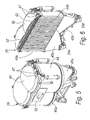
- an apparatus for removal of material by suction, particularly of soil, according to the invention is generally designated by the reference numeral 10.
- the apparatus 10 comprises, supported by the chassis 11 of a means of transport 12, a partial vacuum unit 25 for a collection tank 14, to which the aspirated material is conveyed by associated suction means, described in greater detail hereinafter.
- the tank 14 is substantially cylindrical and is closed by two bottoms, one of which, the unloading bottom 21, can be opened during the step for emptying the tank 14.
- the bottoms have a conveniently cambered shape.
- the cylindrical shape of the tank 14 and the cambered shape of the bottoms that close it are such as to prevent the implosion of the tank 14 as a consequence of the stresses imposed by the substantial partial vacuum generated therein by the partial vacuum unit 25 for suction.
- the tank 14 is installed on unloading means, which are suitable to lift it at one end in order to allow its emptying by gravity of the material accumulated therein.
- the tank 14 is generally suitable to unload onto a dump body 50, of the type that can be removed from a chassis, by means of which the soil aspirated in the tank 14 is moved away from the work area.
- the unloading means comprise a frame 16, which is coupled rotatably to the chassis 11 by interposing a center bearing 17, which rotates about a vertical axis and is provided with means for actuating the rotation of the frame 16 with respect to the chassis 11.
- the frame 16 in turn is composed of a base 18 for connection to the center bearing 17.
- a supporting structure 19 for the tank 14 is associated with the base 18.
- the structure 19 has multiple movement means for positioning the tank 14, so that it discharges outside the footprint of the means of transport 12.
- Said multiple movement means comprise two first actuators 20.
- the first actuators 20 are arranged between the structure 19 and the base 18 in order to lift the structure 19 with respect to the base 18 on the side of the unloading bottom 21 of the tank 14, in order to raise the bottom 21 so that it lies above the edge of the adjacent dump body 50.
- the structure 19 is connected to the base 18 by way of pivoting means, constituted here by two pivots 49.
- the multiple movement means further comprise second actuators 22, which are interposed between the structure 19 and the opposite part of the tank 14 with respect to the openable bottom 21.
- the second actuators 22 are adapted to tilt the tank 14 to unload it into the dump body 50, as exemplified in Figure 4.
- Figure 4 also shows that the extension of the first actuators 20 allows the structure 19 to tilt so that the openable unloading bottom 21 is arranged for unloading above the dump body 50, even if the dump body 50 has sides which are higher than the distance from the ground of the lower part of the tank 14 in the basic operating configuration, as exemplified in Figure 2.
- the multiple movement means are completed by two telescopic arms 19a of the structure 19.
- the telescopic arms 19a are joined at their ends by a cross-member 19b, to which the tank 14 is pivoted proximate to its unloading bottom 21.
- the arms 19a can be extended/retracted by way of fluid-operated actuation means or other equivalent means which can extend from complementarily shaped receptacles of the structure 19.
- the arms 19a are suitable to move the tank 14 away from the volume occupied by the means of transport 12, as shown in Figure 4.
- the center bearing 17 has an axial hole 23 for the passage of the couplings between the suction port 14a of the tank 14 with underlying suction ducts 24.
- the means for actuating the rotation of the frame 16 with respect to the chassis 11 are constituted by a motor drive, which is not shown for the sake of simplicity.
- the center bearing 17 allows the tank 14 to rotate through at least 180° about the vertical axis of the center bearing.
- the tank 14 can be arranged, for the unloading operations, in a chosen point within the rotation arc, and particularly in the lateral and rear regions of the means of transport 12 that supports it.
- the suction means cited above are formed by an articulated arm 27 for supporting and positioning a suction tube 28.
- the articulated arm 27 is rigidly coupled to the supporting structure 19 of the tank 14 and is fixed to a bracket 29 which protrudes from the structure 19.
- the articulated arm 27 is therefore also orientable by means of the center bearing 17; i.e., by turning the frame 16 to which the bracket 29 belongs, the arm 27 can be arranged so as to work in any point of the arc allowed by the center bearing 17.
- the articulated arm 27 is composed of a turret 30, which is fixed to the bracket 29, the head 31 of which can rotate about an axis which is perpendicular to the ground.
- a plurality of consecutive and mutually articulated tube guiding sectors 32, 33 and 34 are hinged from the head 31 and support the tube 28.
- the rotation of the head 31 with respect to the turret 30 is actuated and controlled by means of a motor drive 49, while the tube guiding sectors 32, 33 and 34 can be moved with respect to a consecutive member by way of additional actuation cylinders 51.
- the partial vacuum unit 25 comprises, within a sound-absorbing cabinet 37, a pump 38 provided in input with a pump protection filter 41 and with a first muffler 39, and in output with a second muffler 40.
- Such a partial vacuum unit is capable of working in an urban environment without causing particular noise pollution.
- the apparatus 10 according to the invention is suitable for aspirating not only soil but also all the various materials produced by excavations, such as mud, liquids, dust or other debris.
- the partial vacuum unit 25 is suitable to aspirate from the tank 14 with the interposition of a filtration device 26, which is functionally connected to the tank 14 by way of the suction ducts 24.
- the filtration device 26 is of the type constituted by a box-like body 44 with a tapering bottom for collecting the filtrate and an upper lid 46, inside which there are shell-and-tube assemblies 43 which are at least partially covered by dust retention sleeves.
- the device 26, to which the present invention also relates is characterized in that the box-like body 44 is shaped like two cylinders with vertical and parallel axes, which partially intersect each other so as to form two cylindrical filtration compartments 44a and 44b which open laterally into each other.
- Said shape of the body 44 allows, for an equal longitudinal space occupation (with respect to the length of the means of transport 12) with a filtration device of the known single-cylinder type, a larger volume which can be fitted with shell-and-tube assemblies for filtration.
- the filtration device 26 according to the invention therefore has a higher filtration capacity than known types of filtration device having a cylindrical body.
- the two cylindrical compartments 44a and 44b are each provided, in a lower region, with a conical bottom, designated respectively by the reference numerals 45a and 45b, for collecting the filtrate.
- Known devices also have a conical bottom, but the two conical bottoms 45a and 45b arranged side-by-side have lateral surfaces which are more inclined than the single central conical bottom of known devices, consequently improving the sliding of the filtrate toward the underlying discharges.
- the aspirated air that arrives from the ducts 24 enters the lower ports, not shown for the sake of simplicity, of the conical bottoms 45a and 45b, and flows out toward the partial vacuum unit 25 from the upper port 53.
- the upper port 53 is connected directly to the intake 54 of the partial vacuum unit, which leads to the pump protection filter 41.
- a plurality of tubular blowers 47 are provided between the shell-and-tube assemblies 43 and the lid 46 and are suitable to blow air in countercurrent onto the shell-and-tube assemblies 43 and onto the sleeves that surround them, in order to clean the device periodically.
- outlets 55a and 55b are visible at the end of the conical bottoms 45a and 45b and the filtrate accumulated therein is extracted periodically through said outlets.
- the filtration device 26 can be adopted for an apparatus 10 which aspirates earth, solid and muddy debris, and, if modified adequately, even liquids.
- the invention also relates to a truck provided with an apparatus for removal by suction particularly of soil.
- Said truck i.e., the means of transport designated above by the reference numeral 12, therefore comprises, supported by its chassis 11, a partial vacuum assembly 25 for a collection tank 14, to which the aspirated material is conveyed by suction means as described above.
- the tank 14 is installed on unloading means suitable to lift the tank 14 at one end in order to empty it.
- the truck 12 is characterized in that the unloading means are constituted by a frame 16 which is coupled rotatably to the chassis 11 by interposing a center bearing 17, which rotates about a vertical axis and is provided with means for actuating the rotation of the frame 16 with respect to the chassis 11.
- the frame 16 has a base 18 for connection to the center bearing 17; a structure 19 for supporting the tank 14 is associated with the base 18.
- the structure 19 is connected to the base 18 at one end by virtue of pivoting means, on the opposite side by virtue of first actuators 20, which are suitable to lift the part of the structure 19 on which the tank 14 is directed with its openable unloading bottom 21.
- the tank 14 is moved, with respect to the structure 19 that supports it, by second actuators 22, which are interposed between the structure 19 and the opposite part of the tank 14 with respect to the openable unloading bottom 21.
- the second actuators 22 are suitable to tilt the tank 14 to unload it.
- the partial vacuum unit 25 on board the truck 12 is suitable to aspirate from the tank 14 with the interposition of a filtration device 26 functionally connected to the tank 14 by way of the suction ducts 24.
- the suction means provided on the truck 12 are formed by an articulated arm 27 for supporting and positioning a suction tube 28 for soil or other generic materials produced by excavations, such as mud, liquids, dust or other debris.
- the truck 12 is provided with a partial vacuum unit 25 and with a filtration device 26 as described above.
- the present invention provides an apparatus which allows higher flexibility in the operations for unloading the tank.
- the present invention provides an apparatus which allows to unload the tank also on the sides of the means of transport as well as from the rear as in known apparatuses.
- the present invention provides a filtration device for apparatuses for removal by suction, particularly of soil, which has an increased capacity and reduced space occupation with respect to known filtration devices.
- the present invention provides a truck with an onboard apparatus for removal of material by suction, particularly of soil.
- the present invention provides an apparatus which can operate in confined spaces and at least as efficiently as known types of apparatus, and has a suction capacity at least equal to that of known apparatuses.
- the present invention provides an apparatus which can be managed easily even by an operator who lacks particular prior training.
- the present invention provides an apparatus for removal by suction, particularly of soil, a filtration device, and a truck with an onboard apparatus for removal by suction, particularly of soil, which can be manufactured with known systems and technologies.
- the materials employed may be any according to requirements and to the state of the art.
Landscapes
- Engineering & Computer Science (AREA)
- Mechanical Engineering (AREA)
- Transportation (AREA)
- Health & Medical Sciences (AREA)
- Public Health (AREA)
- Filtration Of Liquid (AREA)
- Treatment Of Sludge (AREA)
- Load-Engaging Elements For Cranes (AREA)
- Placing Or Removing Of Piles Or Sheet Piles, Or Accessories Thereof (AREA)
- Excavating Of Shafts Or Tunnels (AREA)
- Manipulator (AREA)
- Hooks, Suction Cups, And Attachment By Adhesive Means (AREA)
Applications Claiming Priority (1)
| Application Number | Priority Date | Filing Date | Title |
|---|---|---|---|
| IT000110A ITPD20050110A1 (it) | 2005-04-21 | 2005-04-21 | Attezzatura per l'asporto particolarmente di terra mediante aspirazione |
Publications (3)
| Publication Number | Publication Date |
|---|---|
| EP1714830A2 true EP1714830A2 (de) | 2006-10-25 |
| EP1714830A3 EP1714830A3 (de) | 2007-07-11 |
| EP1714830B1 EP1714830B1 (de) | 2009-06-10 |
Family
ID=36684765
Family Applications (1)
| Application Number | Title | Priority Date | Filing Date |
|---|---|---|---|
| EP06112792A Not-in-force EP1714830B1 (de) | 2005-04-21 | 2006-04-20 | Absaugeinrichtung, insbesondere zum Entfernen von Erde |
Country Status (7)
| Country | Link |
|---|---|
| US (1) | US7451521B2 (de) |
| EP (1) | EP1714830B1 (de) |
| AT (1) | ATE433394T1 (de) |
| CA (1) | CA2544097A1 (de) |
| DE (1) | DE602006007190D1 (de) |
| ES (1) | ES2328843T3 (de) |
| IT (1) | ITPD20050110A1 (de) |
Cited By (4)
| Publication number | Priority date | Publication date | Assignee | Title |
|---|---|---|---|---|
| EP1790526A3 (de) * | 2005-11-23 | 2008-07-30 | Rolligon Corporation | LKW mit einer Vielzahl von Tanks bzw. Behältern |
| EP2181888A1 (de) * | 2008-10-28 | 2010-05-05 | Cappellotto S.p.A. | Absaugvorrichtung für brennbares Material |
| EP2730460A1 (de) * | 2012-11-13 | 2014-05-14 | Vac-U-Digga R&D Pty Ltd | Transportabler Abfallbehandlungsbehälter |
| FR3011208A1 (fr) * | 2013-09-30 | 2015-04-03 | Aspir | Systeme de recuperation et de stockage d'un contenu et vehicule equipe d'un tel systeme |
Families Citing this family (18)
| Publication number | Priority date | Publication date | Assignee | Title |
|---|---|---|---|---|
| US20100047047A1 (en) * | 2008-08-21 | 2010-02-25 | Mayer Timothy G | Refuse truck having double barrel storage and methods |
| US8328290B2 (en) * | 2009-08-06 | 2012-12-11 | Advanced Waste Services, Inc. | Expanded size sludge vacuum tanker |
| US9719230B2 (en) * | 2010-01-04 | 2017-08-01 | Vac-Tron Equipment, Llc | Mobile vacuum with remote debris tank |
| US9821953B2 (en) * | 2011-05-02 | 2017-11-21 | The Charles Machine Works, Inc. | Apparatus for sealing a vacuum tank door |
| US9057180B1 (en) * | 2011-05-02 | 2015-06-16 | The Charles Machine Works, Inc. | Apparatus for sealing a vacuum tank door |
| US9687890B2 (en) | 2011-06-14 | 2017-06-27 | Independence Enterprises, Inc | Fluid collection system and related methods |
| US20140061019A1 (en) * | 2012-02-22 | 2014-03-06 | John J. Hagerty, JR. | Method and Apparatus for Reducing Organic Waste by Rotary Desiccation |
| USD714692S1 (en) | 2012-11-13 | 2014-10-07 | Vac-U-Digga R&D Pty Ltd | Transportable liquid waste processing tank |
| CA2891727C (en) * | 2015-05-19 | 2020-12-15 | Trinity Group Ltd. | Blower drive system for a vacuum truck |
| US10221602B2 (en) | 2016-04-06 | 2019-03-05 | The Charles Machine Works, Inc. | Vacuum system |
| CN106988256A (zh) * | 2017-05-21 | 2017-07-28 | 成都蒲江珂贤科技有限公司 | 一种共用式垃圾清理车 |
| CN107288085A (zh) * | 2017-08-17 | 2017-10-24 | 苏州市玄天环保科技有限公司 | 一种环保安全垃圾清洁车 |
| US11059682B2 (en) | 2017-12-21 | 2021-07-13 | The Charles Machine Works, Inc. | Offloading vacuum tank |
| USD895914S1 (en) | 2018-02-15 | 2020-09-08 | The Charles Machine Works, Inc. | Vacuum system |
| CN112942475B (zh) * | 2021-02-04 | 2022-09-30 | 广东鹏裕建设有限公司 | 高效双循环清淤系统 |
| CN113152555B (zh) * | 2021-04-20 | 2023-04-28 | 福建侨龙应急装备股份有限公司 | 一种应急救援设备 |
| CN214883967U (zh) * | 2021-04-20 | 2021-11-26 | 福建侨龙应急装备股份有限公司 | 一种抽吸挖掘机器人及其应急救援设备 |
| IT202300022323A1 (it) | 2023-10-25 | 2025-04-25 | Grotti Srl | Dispositivo di aspirazione di materiale fresato, attrezzatura di scarifica e aspirazione di relativo materiale fresato, e rispettivo procedimento |
Family Cites Families (12)
| Publication number | Priority date | Publication date | Assignee | Title |
|---|---|---|---|---|
| US2621072A (en) * | 1949-02-16 | 1952-12-09 | Judson Ayres Scott | Horizontally swinging dump body truck |
| GB809154A (en) | 1954-08-30 | 1959-02-18 | Deighton S Patent Flue & Tube | Improvements relating to conservancy collectors for night soil collection |
| US4017281A (en) * | 1975-10-02 | 1977-04-12 | Duncan Johnstone | Industrial vacuum loader with dust removal means for bag house filtration system |
| DE2727492C3 (de) | 1977-06-18 | 1980-08-21 | Messerschmitt-Boelkow-Blohm Gmbh, 8000 Muenchen | Müllsammeifahrzeug mit einem Müllcontainer und einem Ladewerk |
| US4193159A (en) * | 1978-01-20 | 1980-03-18 | Beard Benjamin F Iii | Mobile cleaning apparatus for removing debris from the surface of parking lots and the like |
| US4227893A (en) * | 1978-09-01 | 1980-10-14 | Peabody-Myers Corporation | Mobile vacuum loader |
| JPS60213532A (ja) * | 1984-04-06 | 1985-10-25 | Kayaba Ind Co Ltd | 粉粒状物運搬車 |
| US4659262A (en) * | 1985-03-04 | 1987-04-21 | Cyclonaire Bulk Cargo Systems, Inc. | Mobile self contained pneumatic conveying system |
| US4935984A (en) * | 1989-02-09 | 1990-06-26 | Guzzler Manufactureing, Inc. | Vacuum refuse collecting vehicle |
| US5596788A (en) * | 1994-11-14 | 1997-01-28 | Linville; Ronny E. | Vacuum sweeper vehicle with lightweight hopper |
| US5996171A (en) * | 1997-02-04 | 1999-12-07 | Bowers; Randy | Vacuum truck system |
| US6752467B1 (en) * | 2002-02-14 | 2004-06-22 | Vac-Con, Inc. | Vacuum truck dump container apparatus |
-
2005
- 2005-04-21 IT IT000110A patent/ITPD20050110A1/it unknown
-
2006
- 2006-04-14 US US11/403,855 patent/US7451521B2/en active Active
- 2006-04-19 CA CA002544097A patent/CA2544097A1/en not_active Abandoned
- 2006-04-20 DE DE602006007190T patent/DE602006007190D1/de active Active
- 2006-04-20 EP EP06112792A patent/EP1714830B1/de not_active Not-in-force
- 2006-04-20 AT AT06112792T patent/ATE433394T1/de not_active IP Right Cessation
- 2006-04-20 ES ES06112792T patent/ES2328843T3/es active Active
Cited By (4)
| Publication number | Priority date | Publication date | Assignee | Title |
|---|---|---|---|---|
| EP1790526A3 (de) * | 2005-11-23 | 2008-07-30 | Rolligon Corporation | LKW mit einer Vielzahl von Tanks bzw. Behältern |
| EP2181888A1 (de) * | 2008-10-28 | 2010-05-05 | Cappellotto S.p.A. | Absaugvorrichtung für brennbares Material |
| EP2730460A1 (de) * | 2012-11-13 | 2014-05-14 | Vac-U-Digga R&D Pty Ltd | Transportabler Abfallbehandlungsbehälter |
| FR3011208A1 (fr) * | 2013-09-30 | 2015-04-03 | Aspir | Systeme de recuperation et de stockage d'un contenu et vehicule equipe d'un tel systeme |
Also Published As
| Publication number | Publication date |
|---|---|
| ATE433394T1 (de) | 2009-06-15 |
| EP1714830B1 (de) | 2009-06-10 |
| ITPD20050110A1 (it) | 2006-10-22 |
| ES2328843T3 (es) | 2009-11-18 |
| US7451521B2 (en) | 2008-11-18 |
| EP1714830A3 (de) | 2007-07-11 |
| US20060236499A1 (en) | 2006-10-26 |
| DE602006007190D1 (de) | 2009-07-23 |
| CA2544097A1 (en) | 2006-10-21 |
Similar Documents
| Publication | Publication Date | Title |
|---|---|---|
| EP1714830B1 (de) | Absaugeinrichtung, insbesondere zum Entfernen von Erde | |
| CA2776853C (en) | Debris collecting system | |
| US20200123736A1 (en) | Suction dredger having a swiveling filter unit | |
| US10131387B2 (en) | Construction vehicle having a tippable chassis | |
| CN104175939B (zh) | 一种吸运车 | |
| CN109024414B (zh) | 扫路车及扫路方法 | |
| CN105297661B (zh) | 清扫车 | |
| US8776303B2 (en) | Articulating vacuum hose | |
| EP0476483B1 (de) | Universelle Kehreinheit | |
| CN106638417B (zh) | 一种适用于透水路面的清洁养护车、方法及应用 | |
| US3242521A (en) | Street cleaning machine | |
| KR200346321Y1 (ko) | 노면 청소기 | |
| CN108978555B (zh) | 垃圾箱 | |
| CN117086034A (zh) | 一种铲斗结构及管道清淤机器人 | |
| JPS5931779Y2 (ja) | 車載除じん機 | |
| CN215166437U (zh) | 一种抽吸臂及真空抽吸车 | |
| CN219430983U (zh) | 一种抓斗清淤车 | |
| CN120465546B (zh) | 煤矿用气动履带清仓机 | |
| JPH09250167A (ja) | 側溝掃除機 | |
| WO2004001138A1 (en) | Compact, high-tipping, self-propelled road sweeper | |
| WO2017136927A1 (en) | Hydrovac tank | |
| CN210946635U (zh) | 吸尘车 | |
| JPS5934585Y2 (ja) | 車載除じん排土機 | |
| CN211312370U (zh) | 一种清扫车 | |
| JP4234813B2 (ja) | ホッパダンプ機構 |
Legal Events
| Date | Code | Title | Description |
|---|---|---|---|
| PUAI | Public reference made under article 153(3) epc to a published international application that has entered the european phase |
Free format text: ORIGINAL CODE: 0009012 |
|
| AK | Designated contracting states |
Kind code of ref document: A2 Designated state(s): AT BE BG CH CY CZ DE DK EE ES FI FR GB GR HU IE IS IT LI LT LU LV MC NL PL PT RO SE SI SK TR |
|
| AX | Request for extension of the european patent |
Extension state: AL BA HR MK YU |
|
| PUAL | Search report despatched |
Free format text: ORIGINAL CODE: 0009013 |
|
| AK | Designated contracting states |
Kind code of ref document: A3 Designated state(s): AT BE BG CH CY CZ DE DK EE ES FI FR GB GR HU IE IS IT LI LT LU LV MC NL PL PT RO SE SI SK TR |
|
| AX | Request for extension of the european patent |
Extension state: AL BA HR MK YU |
|
| RIC1 | Information provided on ipc code assigned before grant |
Ipc: B65G 65/23 20060101ALI20070604BHEP Ipc: B60P 3/22 20060101ALI20070604BHEP Ipc: B60P 1/60 20060101AFI20060725BHEP Ipc: B60P 1/34 20060101ALI20070604BHEP |
|
| 17P | Request for examination filed |
Effective date: 20071221 |
|
| 17Q | First examination report despatched |
Effective date: 20080212 |
|
| AKX | Designation fees paid |
Designated state(s): AT BE BG CH CY CZ DE DK EE ES FI FR GB GR HU IE IS IT LI LT LU LV MC NL PL PT RO SE SI SK TR |
|
| GRAP | Despatch of communication of intention to grant a patent |
Free format text: ORIGINAL CODE: EPIDOSNIGR1 |
|
| GRAS | Grant fee paid |
Free format text: ORIGINAL CODE: EPIDOSNIGR3 |
|
| GRAA | (expected) grant |
Free format text: ORIGINAL CODE: 0009210 |
|
| AK | Designated contracting states |
Kind code of ref document: B1 Designated state(s): AT BE BG CH CY CZ DE DK EE ES FI FR GB GR HU IE IS IT LI LT LU LV MC NL PL PT RO SE SI SK TR |
|
| REG | Reference to a national code |
Ref country code: GB Ref legal event code: FG4D |
|
| REG | Reference to a national code |
Ref country code: CH Ref legal event code: EP |
|
| REG | Reference to a national code |
Ref country code: IE Ref legal event code: FG4D |
|
| REF | Corresponds to: |
Ref document number: 602006007190 Country of ref document: DE Date of ref document: 20090723 Kind code of ref document: P |
|
| PG25 | Lapsed in a contracting state [announced via postgrant information from national office to epo] |
Ref country code: AT Free format text: LAPSE BECAUSE OF FAILURE TO SUBMIT A TRANSLATION OF THE DESCRIPTION OR TO PAY THE FEE WITHIN THE PRESCRIBED TIME-LIMIT Effective date: 20090610 Ref country code: LT Free format text: LAPSE BECAUSE OF FAILURE TO SUBMIT A TRANSLATION OF THE DESCRIPTION OR TO PAY THE FEE WITHIN THE PRESCRIBED TIME-LIMIT Effective date: 20090610 Ref country code: FI Free format text: LAPSE BECAUSE OF FAILURE TO SUBMIT A TRANSLATION OF THE DESCRIPTION OR TO PAY THE FEE WITHIN THE PRESCRIBED TIME-LIMIT Effective date: 20090610 |
|
| NLV1 | Nl: lapsed or annulled due to failure to fulfill the requirements of art. 29p and 29m of the patents act | ||
| REG | Reference to a national code |
Ref country code: ES Ref legal event code: FG2A Ref document number: 2328843 Country of ref document: ES Kind code of ref document: T3 |
|
| PG25 | Lapsed in a contracting state [announced via postgrant information from national office to epo] |
Ref country code: NL Free format text: LAPSE BECAUSE OF FAILURE TO SUBMIT A TRANSLATION OF THE DESCRIPTION OR TO PAY THE FEE WITHIN THE PRESCRIBED TIME-LIMIT Effective date: 20090610 Ref country code: SI Free format text: LAPSE BECAUSE OF FAILURE TO SUBMIT A TRANSLATION OF THE DESCRIPTION OR TO PAY THE FEE WITHIN THE PRESCRIBED TIME-LIMIT Effective date: 20090610 Ref country code: PL Free format text: LAPSE BECAUSE OF FAILURE TO SUBMIT A TRANSLATION OF THE DESCRIPTION OR TO PAY THE FEE WITHIN THE PRESCRIBED TIME-LIMIT Effective date: 20090610 Ref country code: LV Free format text: LAPSE BECAUSE OF FAILURE TO SUBMIT A TRANSLATION OF THE DESCRIPTION OR TO PAY THE FEE WITHIN THE PRESCRIBED TIME-LIMIT Effective date: 20090610 Ref country code: SE Free format text: LAPSE BECAUSE OF FAILURE TO SUBMIT A TRANSLATION OF THE DESCRIPTION OR TO PAY THE FEE WITHIN THE PRESCRIBED TIME-LIMIT Effective date: 20090910 |
|
| PG25 | Lapsed in a contracting state [announced via postgrant information from national office to epo] |
Ref country code: CZ Free format text: LAPSE BECAUSE OF FAILURE TO SUBMIT A TRANSLATION OF THE DESCRIPTION OR TO PAY THE FEE WITHIN THE PRESCRIBED TIME-LIMIT Effective date: 20090610 Ref country code: IS Free format text: LAPSE BECAUSE OF FAILURE TO SUBMIT A TRANSLATION OF THE DESCRIPTION OR TO PAY THE FEE WITHIN THE PRESCRIBED TIME-LIMIT Effective date: 20091010 Ref country code: RO Free format text: LAPSE BECAUSE OF FAILURE TO SUBMIT A TRANSLATION OF THE DESCRIPTION OR TO PAY THE FEE WITHIN THE PRESCRIBED TIME-LIMIT Effective date: 20090610 Ref country code: EE Free format text: LAPSE BECAUSE OF FAILURE TO SUBMIT A TRANSLATION OF THE DESCRIPTION OR TO PAY THE FEE WITHIN THE PRESCRIBED TIME-LIMIT Effective date: 20090610 |
|
| PG25 | Lapsed in a contracting state [announced via postgrant information from national office to epo] |
Ref country code: BE Free format text: LAPSE BECAUSE OF FAILURE TO SUBMIT A TRANSLATION OF THE DESCRIPTION OR TO PAY THE FEE WITHIN THE PRESCRIBED TIME-LIMIT Effective date: 20090610 Ref country code: SK Free format text: LAPSE BECAUSE OF FAILURE TO SUBMIT A TRANSLATION OF THE DESCRIPTION OR TO PAY THE FEE WITHIN THE PRESCRIBED TIME-LIMIT Effective date: 20090610 |
|
| PG25 | Lapsed in a contracting state [announced via postgrant information from national office to epo] |
Ref country code: PT Free format text: LAPSE BECAUSE OF FAILURE TO SUBMIT A TRANSLATION OF THE DESCRIPTION OR TO PAY THE FEE WITHIN THE PRESCRIBED TIME-LIMIT Effective date: 20091010 Ref country code: BG Free format text: LAPSE BECAUSE OF FAILURE TO SUBMIT A TRANSLATION OF THE DESCRIPTION OR TO PAY THE FEE WITHIN THE PRESCRIBED TIME-LIMIT Effective date: 20090910 |
|
| PLBE | No opposition filed within time limit |
Free format text: ORIGINAL CODE: 0009261 |
|
| STAA | Information on the status of an ep patent application or granted ep patent |
Free format text: STATUS: NO OPPOSITION FILED WITHIN TIME LIMIT |
|
| PG25 | Lapsed in a contracting state [announced via postgrant information from national office to epo] |
Ref country code: DK Free format text: LAPSE BECAUSE OF FAILURE TO SUBMIT A TRANSLATION OF THE DESCRIPTION OR TO PAY THE FEE WITHIN THE PRESCRIBED TIME-LIMIT Effective date: 20090610 |
|
| 26N | No opposition filed |
Effective date: 20100311 |
|
| PGFP | Annual fee paid to national office [announced via postgrant information from national office to epo] |
Ref country code: FR Payment date: 20100617 Year of fee payment: 5 |
|
| PGFP | Annual fee paid to national office [announced via postgrant information from national office to epo] |
Ref country code: IT Payment date: 20100528 Year of fee payment: 5 |
|
| PG25 | Lapsed in a contracting state [announced via postgrant information from national office to epo] |
Ref country code: GR Free format text: LAPSE BECAUSE OF FAILURE TO SUBMIT A TRANSLATION OF THE DESCRIPTION OR TO PAY THE FEE WITHIN THE PRESCRIBED TIME-LIMIT Effective date: 20090911 |
|
| PGFP | Annual fee paid to national office [announced via postgrant information from national office to epo] |
Ref country code: ES Payment date: 20100625 Year of fee payment: 5 |
|
| PG25 | Lapsed in a contracting state [announced via postgrant information from national office to epo] |
Ref country code: MC Free format text: LAPSE BECAUSE OF NON-PAYMENT OF DUE FEES Effective date: 20100430 |
|
| PGFP | Annual fee paid to national office [announced via postgrant information from national office to epo] |
Ref country code: DE Payment date: 20100910 Year of fee payment: 5 |
|
| REG | Reference to a national code |
Ref country code: CH Ref legal event code: PL |
|
| GBPC | Gb: european patent ceased through non-payment of renewal fee |
Effective date: 20100420 |
|
| PG25 | Lapsed in a contracting state [announced via postgrant information from national office to epo] |
Ref country code: IE Free format text: LAPSE BECAUSE OF NON-PAYMENT OF DUE FEES Effective date: 20100420 |
|
| PG25 | Lapsed in a contracting state [announced via postgrant information from national office to epo] |
Ref country code: LI Free format text: LAPSE BECAUSE OF NON-PAYMENT OF DUE FEES Effective date: 20100430 Ref country code: CH Free format text: LAPSE BECAUSE OF NON-PAYMENT OF DUE FEES Effective date: 20100430 |
|
| PG25 | Lapsed in a contracting state [announced via postgrant information from national office to epo] |
Ref country code: GB Free format text: LAPSE BECAUSE OF NON-PAYMENT OF DUE FEES Effective date: 20100420 |
|
| REG | Reference to a national code |
Ref country code: FR Ref legal event code: ST Effective date: 20111230 |
|
| PG25 | Lapsed in a contracting state [announced via postgrant information from national office to epo] |
Ref country code: DE Free format text: LAPSE BECAUSE OF NON-PAYMENT OF DUE FEES Effective date: 20111101 Ref country code: FR Free format text: LAPSE BECAUSE OF NON-PAYMENT OF DUE FEES Effective date: 20110502 |
|
| REG | Reference to a national code |
Ref country code: DE Ref legal event code: R119 Ref document number: 602006007190 Country of ref document: DE Effective date: 20111101 |
|
| PG25 | Lapsed in a contracting state [announced via postgrant information from national office to epo] |
Ref country code: IT Free format text: LAPSE BECAUSE OF NON-PAYMENT OF DUE FEES Effective date: 20110420 |
|
| REG | Reference to a national code |
Ref country code: ES Ref legal event code: FD2A Effective date: 20120524 |
|
| PG25 | Lapsed in a contracting state [announced via postgrant information from national office to epo] |
Ref country code: ES Free format text: LAPSE BECAUSE OF NON-PAYMENT OF DUE FEES Effective date: 20110421 |
|
| PG25 | Lapsed in a contracting state [announced via postgrant information from national office to epo] |
Ref country code: CY Free format text: LAPSE BECAUSE OF FAILURE TO SUBMIT A TRANSLATION OF THE DESCRIPTION OR TO PAY THE FEE WITHIN THE PRESCRIBED TIME-LIMIT Effective date: 20090610 |
|
| PG25 | Lapsed in a contracting state [announced via postgrant information from national office to epo] |
Ref country code: LU Free format text: LAPSE BECAUSE OF NON-PAYMENT OF DUE FEES Effective date: 20100420 Ref country code: HU Free format text: LAPSE BECAUSE OF FAILURE TO SUBMIT A TRANSLATION OF THE DESCRIPTION OR TO PAY THE FEE WITHIN THE PRESCRIBED TIME-LIMIT Effective date: 20091211 |
|
| PG25 | Lapsed in a contracting state [announced via postgrant information from national office to epo] |
Ref country code: TR Free format text: LAPSE BECAUSE OF FAILURE TO SUBMIT A TRANSLATION OF THE DESCRIPTION OR TO PAY THE FEE WITHIN THE PRESCRIBED TIME-LIMIT Effective date: 20090610 |