EP1714829A2 - Vorrichtung zum Be-und Entladen der Ladefläche eines Fahrzeugs, insbesondere Lastkraftwagens, mit Gütern - Google Patents
Vorrichtung zum Be-und Entladen der Ladefläche eines Fahrzeugs, insbesondere Lastkraftwagens, mit Gütern Download PDFInfo
- Publication number
- EP1714829A2 EP1714829A2 EP06003539A EP06003539A EP1714829A2 EP 1714829 A2 EP1714829 A2 EP 1714829A2 EP 06003539 A EP06003539 A EP 06003539A EP 06003539 A EP06003539 A EP 06003539A EP 1714829 A2 EP1714829 A2 EP 1714829A2
- Authority
- EP
- European Patent Office
- Prior art keywords
- conveyor belt
- loading
- drive
- drive shaft
- conveyor
- Prior art date
- Legal status (The legal status is an assumption and is not a legal conclusion. Google has not performed a legal analysis and makes no representation as to the accuracy of the status listed.)
- Withdrawn
Links
- 238000011161 development Methods 0.000 description 4
- 238000013461 design Methods 0.000 description 3
- 229910000831 Steel Inorganic materials 0.000 description 2
- 238000009434 installation Methods 0.000 description 2
- 238000012423 maintenance Methods 0.000 description 2
- 238000000034 method Methods 0.000 description 2
- 239000010959 steel Substances 0.000 description 2
- 238000006073 displacement reaction Methods 0.000 description 1
- 238000001746 injection moulding Methods 0.000 description 1
- 238000012986 modification Methods 0.000 description 1
- 230000004048 modification Effects 0.000 description 1
- 238000003032 molecular docking Methods 0.000 description 1
- 239000000243 solution Substances 0.000 description 1
- 239000002023 wood Substances 0.000 description 1
Images




Classifications
-
- B—PERFORMING OPERATIONS; TRANSPORTING
- B60—VEHICLES IN GENERAL
- B60P—VEHICLES ADAPTED FOR LOAD TRANSPORTATION OR TO TRANSPORT, TO CARRY, OR TO COMPRISE SPECIAL LOADS OR OBJECTS
- B60P1/00—Vehicles predominantly for transporting loads and modified to facilitate loading, consolidating the load, or unloading
- B60P1/36—Vehicles predominantly for transporting loads and modified to facilitate loading, consolidating the load, or unloading using endless chains or belts thereon
- B60P1/38—Vehicles predominantly for transporting loads and modified to facilitate loading, consolidating the load, or unloading using endless chains or belts thereon forming the main load-transporting element or part thereof
Definitions
- the invention relates to a device for loading and unloading the loading area of a vehicle, in particular a truck, with goods according to the preamble of claim 1.
- the basic principle of a known loading and unloading device consists in a conveyor belt, which is located on the loading area or defines the loading area and which is movable in the longitudinal direction of the vehicle on the loading area. As the conveyor belt advances as viewed in the direction of travel of the vehicle, goods applied from the rear are successively conveyed forward towards the driver's cab. The unloading takes place analogously in the reverse manner, by the conveyor belt is driven in opposite directions.
- the known loading and unloading using a conveyor belt have several disadvantages.
- the known devices sometimes have a large height. As a result, cargo space is lost.
- the devices must be adapted individually to the respective vehicle. This results in long installation times.
- the known devices sometimes require several drives, which is technically complicated.
- the known devices are sometimes relatively heavy. Since the known devices sometimes consist of relatively many items, the reliability not optimal. This requires frequent maintenance.
- the conveyor belts must be partially replaced completely if damage has occurred.
- the known loading and unloading devices are not always passable with hand pallet trucks and light trucks.
- the invention has for its object to provide a device for loading and unloading the cargo area of a vehicle, especially a truck, with goods of the type described with an improved conveyor belt system.
- the basic idea of the loading and unloading device according to the invention consists in a special conveyor belt using transverse link elements.
- These link elements are characterized by a variety of advantages. Thus, different lengths of conveyor belts can be produced in a technically simple manner from the link elements. It is only necessary to connect the link elements according to each other.
- the individual link elements of the link belt are easily interchangeable if damaged, without the entire conveyor belt must be replaced.
- the link elements further have a width such that they cover the entire cargo area of the vehicle. It is readily possible to arrange several conveyor belts next to each other, as will be explained later.
- the link elements according to claim 2 made of plastic. This has the advantage that the link elements can be produced in a technically simple manner in a corresponding injection molding tool.
- a further preferred embodiment proposes claim 3 in such a way that it is at the conveyor belt is an endless belt which runs around the end shafts, wherein at one end the shaft may be formed as a drive shaft and at the other end the shaft as a deflection.
- a further preferred embodiment proposes according to claim 4, that the conveyor belt to the length of the cargo area back and forward is movable.
- the basic principle is thus that, in the initial position of the conveyor belt, the upper run serves as a carrier tape and the lower run as a drawstring. To load the conveyor belt this is simply moved back to the length of the bed, so that virtually with the beginning of the Transport belt the goods can be taken and transported completely inside the vehicle.
- the drive shaft and / or the deflection shaft associated with a tensioning device are arranged. This ensures that the conveyor belt has an optimum tension.
- This sliding plate is a full-surface sliding base for the conveyor belt. It can be a steel substructure with a wooden plate.
- a further preferred embodiment proposes according to claim 8, that a plurality of conveyor belts are arranged parallel to each other and side by side.
- a plurality of conveyor belts are arranged parallel to each other and side by side.
- three conveyor belts are provided, wherein the two outer conveyor belts are mirror images.
- the conveyor belts cover the full width of the conveyor.
- the use of three conveyor belts has the advantage that thereby a special arrangement of a compact drive is possible.
- the development according to claim 9 proposes such a drive, namely a drive means of a drive chain by sprockets are arranged on the drive shafts of the individual conveyor belts.
- a common drive shaft of a drive motor on which in turn sprockets are arranged, which produce the drive with the drive shafts of the conveyor belts via drive chains.
- the drive shaft of the drive motor is preferably associated with a tensioning device.
- the loading area 1 of an otherwise not shown vehicle, in particular a truck, has a device for loading and unloading with goods.
- the loading and unloading device has a total of three mutually parallel and side by side conveyor belts 2.
- the two outer conveyor belts 2 are mirror images of each other.
- the conveyor belts 2 consist of individual, with respect to the transport direction transversely extending link elements 3 made of plastic. These are indicated in Fig. 2 only purely schematically.
- the conveyor belts 2 are each end guided around a drive roller 4 and a deflection roller 5.
- the endless conveyor belt 2 is designed in such a way that in the basic position, the link elements 3 of the upper run are wider than the link elements.
- the upper strand of the conveyor belt 2 serves as a lanyard, while the lower strand of the conveyor belt 2 serves as a drawstring.
- the upper run of the conveyor belt 2 superimposed on a full-surface sliding plate 6. It may be a wood panel with a steel substructure.
- Each of the three drive shafts 4 is associated with a tensioning device 7 for the respective conveyor belt 2.
- a drive motor 8 This is located in the front center of the loading area 1 in the area behind the cab. Assigned to the drive motor 8 is a transverse drive shaft 9. The two ends of the drive shaft 9 each have sprockets 10 in a driplex design. In addition, a clamping device 11 is provided.
- the drive shafts 4 of the conveyor belts 2 in the opposite region between two adjacent conveyor belts 2 each sprockets 12.
- the sprockets 12 of the drive shaft of the middle conveyor belt 2 are simple, while the sprockets 12 of the two outer conveyor belts 2 are executed in duplex-Au Unit.
- the vehicle docks back via a docking station on a stationary conveyor, so that the loading and unloading device according to the invention forms, so to speak, the continuation of this stationary conveyor.
- the stationary controller is connected via a manually pluggable connection with the controller of the loading and unloading device according to the invention. After the start command, the loading or unloading will be carried out automatically.
- the conveyor belts in the empty state are driven so far back until the beginning of the wide link elements 3 is located at the rearmost edge of the loading area 1. Now the loading process begins.
- the estate is transferred from the stationary conveyor to the loading and unloading device of the loading area 1 according to the invention.
- the conveyor belts 2 move forward until the beginning of the wide link belts is in the front of the drive.
- the discharge process is analogous in the reverse manner.
- the advantages of the loading and unloading device according to the invention are in a relatively small height. This results in only a small load space loss.
- the device can still be installed without modification in any standard vehicle. This results in short installation times. Since only one drive is available, simplifies its structural design.
- the loading and unloading device according to the invention is characterized by a low weight compared to conventional systems. Since only a few moving parts are present, this results in continued high reliability. Overall, the system is low maintenance.
- the individual link elements 3 of the conveyor belt 2 are interchangeable in case of damage, without the entire conveyor belt 2 must be replaced. Finally, the loading and unloading device with pallet truck and light trucks is passable.
Landscapes
- Engineering & Computer Science (AREA)
- Transportation (AREA)
- Mechanical Engineering (AREA)
- Loading Or Unloading Of Vehicles (AREA)
Abstract
Description
- Die Erfindung betrifft eine Vorrichtung zum Be- und Entladen der Ladefläche eines Fahrzeugs, insbesondere Lastkraftwagens, mit Gütern nach dem Oberbegriff des Anspruchs 1.
- Es sind automatisch arbeitende Vorrichtungen zum Be- und Entladen der Ladefläche eines Fahrzeugs, insbesondere Lastkraftwagens, mit Gütern bekannt. Das Grundprinzip einer bekannten Be- und Entladevorrichtung besteht in einem Transportband, welches sich auf der Ladefläche befindet bzw. die Ladefläche definiert und welches in Längsrichtung des Fahrzeugs auf der Ladefläche verfahrbar ist. Indem sich das Transportband in Fahrtrichtung des Fahrzeugs gesehen vorwärtsbewegt, werden von hinten aufgebrachte Güter sukzessive nach vorne in Richtung Fahrerhaus befördert. Das Entladen erfolgt analog in umgekehrter Weise, indem das Transportband entgegengesetzt angetrieben wird.
- Die bekannten Be- und Entladevorrichtungen unter Verwendung eines Transportbandes besitzen diverse Nachteile. So haben die bekannten Vorrichtungen teilweise eine große Bauhöhe. Dadurch geht Laderaum verloren. Weiterhin müssen die Vorrichtungen individuell an das jeweilige Fahrzeug angepaßt werden. Dadurch ergeben sich lange Einbauzeiten. Weiterhin benötigen die bekannten Vorrichtungen teilweise mehrere Antriebe, was technisch aufwendig ist. Außerdem sind die bekannten Vorrichtungen teilweise relativ schwer. Da die bekannten Vorrichtungen teilweise auch aus relativ vielen Einzelteilen bestehen, ist die Zuverlässigkeit nicht optimal. Dadurch bedingt sind häufige Wartungen. Weiterhin müssen die Transportbänder teilweise komplett ausgewechselt werden, wenn eine Beschädigung aufgetreten ist. Schließlich sind die bekannten Be- und Entladevorrichtungen nicht immer mit Handhubwagen sowie leichten Staplern befahrbar.
- Davon ausgehend liegt der Erfindung die Aufgabe zugrunde, eine Vorrichtung zum Be- und Entladen der Ladefläche eines Fahrzeugs, insbesondere Lastkraftwagens, mit Gütern der eingangs angegebenen Art mit einem verbesserten Transportbandsystem zu schaffen.
- Die technische Lösung ist gekennzeichnet durch die Merkmale im Kennzeichen des Anspruchs 1.
- Die Grundidee der erfindungsgemäßen Be- und Entladevorrichtung besteht in einem speziellen Transportband unter Verwendung von querverlaufenden Gliederelementen. Diese Gliederelemente zeichnen sich durch eine Vielzahl von Vorteilen aus. So lassen sich aus den Gliederelementen unterschiedlich lange Transportbänder auf technisch einfache Weise herstellen. Es ist lediglich erforderlich, die Gliederelemente entsprechend miteinander zu verbinden. Die einzelnen Gliederelemente des Gliederbandes sind bei Beschädigung leicht austauschbar, ohne daß das komplette Transportband ausgewechselt werden muß. Die Gliederelemente besitzen weiterhin eine derartige Breite, daß sie die gesamte Ladefläche des Fahrzeugs abdecken. Dabei ist es ohne weiteres möglich, mehrere Transportbänder nebeneinander anzuordnen, wie noch auszuführen sein wird.
- In einer bevorzugten Weiterbildung bestehen die Gliederelemente gemäß Anspruch 2 aus Kunststoff. Dies hat den Vorteil, daß die Gliederelemente auf technisch einfache Weise in einem entsprechenden Spritzwerkzeug hergestellt werden können.
- Eine weitere bevorzugte Weiterbildung schlägt Anspruch 3 dergestalt vor, daß es sich bei dem Transportband um ein Endlosband handelt, welches um endseitige Wellen läuft, wobei am einen Ende die Welle als Antriebswelle und am anderen Ende die Welle als Umlenkwelle ausgebildet sein kann.
- Eine weitere bevorzugte Weiterbildung schlägt gemäß Anspruch 4 vor, daß das Transportband um die Länge der Ladefläche zurück und vor verfahrbar ist. Das Grundprinzip besteht somit darin, daß in der Ausgangsstellung des Transportbandes das Obertrum als Tragband und das Untertrum als Zugband dient. Zum Beladen des Transportbandes wird dieses einfach um die Länge der Ladefläche zurück verfahren, so daß quasi mit dem Beginn des Transportbandes die Güter aufgenommen und vollständig ins Innere des Fahrzeugs transportiert werden können.
- Die Weiterbildung hiervon gemäß Anspruch 5 schlägt vor, daß das Tragband breiter ist als das Zugband. Der Vorteil in den unterschiedlichen Breiten besteht darin, daß das Transportband im Bereich mit der geringeren Breite an entsprechenden Spann- sowie Verlagerungsstationen vorbeilaufen kann, so daß dadurch die Möglichkeit gegeben ist, daß bei der Verwendung von mehreren, zueinander parallelen Transportbändern diese eng aneinanderliegen und eine durchgehende Ladefläche definieren.
- Vorzugsweise ist gemäß Anspruch 6 der Antriebswelle und/oder der Umlenkwelle eine Spanneinrichtung zugeordnet. Dadurch ist gewährleistet, daß das Transportband eine optimale Spannung aufweist.
- Die Weiterbildung gemäß Anspruch 7 schlägt vor, daß unterhalb des Obertrums des Transportbandes eine Gleitplatte angeordnet ist. Bei dieser Gleitplatte handelt es sich um eine vollflächige Gleitunterlage für das Transportband. Es kann sich dabei um eine Stahlunterkonstruktion mit einer Holzplatte handeln.
- Eine weitere bevorzugte Weiterbildung schlägt gemäß Anspruch 8 vor, daß mehrere Transportbänder parallel zueinander sowie Seite an Seite angeordnet sind. Vorzugsweise sind drei Transportbänder vorgesehen, wobei die beiden äußeren Transportbänder spiegelbildlich sind. Die Transportbänder decken dabei die volle Breite des Förderers ab. Die Verwendung von drei Transportbändern hat den Vorteil, daß dadurch eine spezielle Anordnung eines kompakten Antriebs möglich ist.
- Die Weiterbildung gemäß Anspruch 9 schlägt einen derartigen Antrieb vor, und zwar einen Antrieb mittels einer Antriebskette, indem auf den Antriebswellen der einzelnen Transportbänder Kettenräder angeordnet sind.
- Die Weiterbildung des Antriebs schlägt gemäß Anspruch 10 eine gemeinsame Antriebswelle eines Antriebsmotors vor, auf welchem wiederum Kettenräder angeordnet sind, welche den Antrieb mit den Antriebswellen der Transportbänder über Antriebsketten herstellen.
- Damit die Antriebskette die notwendige Spannung besitzt, ist der Antriebswelle des Antriebsmotors vorzugsweise eine Spanneinrichtung zugeordnet.
- Ein Ausführungsbeispiel einer erfindungsgemäßen Vorrichtung zum Be- und Entladen der Ladefläche eines Fahrzeugs, insbesondere Lastkraftwagens, mit Gütern wird nachfolgend anhand der Zeichnungen beschrieben. In diesen zeigt:
- Fig. 1
- eine perspektivische Ansicht der Vorrichtung (wobei sich das - nicht dargestellte - Führerhaus des Fahrzeugs rechts befindet);
- Fig. 2
- eine Draufsicht auf die Vorrichtung in Fig. 1;
- Fig. 3
- einen Längsschnitt entlang der Linie A - A in Fig. 2;
- Fig. 4
- einen Querschnitt entlang der Linie C - C in Fig. 2;
- Fig. 5
- eine Vorderansicht der Vorrichtung in Fig. 2;
- Fig. 6
- eine Hinteransicht der Vorrichtung in Fig. 2;
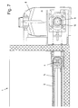
- Fig. 7
- ein Detailausschnitt der Darstellung in Fig. 3 im Bereich des Antriebs;
- Fig. 8
- ein Detailausschnitt der Darstellung in Fig. 4 im Bereich des Antriebs;
- Fig. 9
- ein Detailausschnitt der Darstellung in Fig. 2 im Bereich des Antriebs.
- Die Ladefläche 1 eines ansonsten nicht dargestellten Fahrzeugs, insbesondere Lastkraftwagens, weist eine Vorrichtung zum Be- und Entladen mit Gütern auf.
- Die Be- und Entladevorrichtung weist insgesamt drei zueinander parallele sowie Seite an Seite liegende Transportbänder 2 auf. Dabei sind die beiden äußeren Transportbänder 2 spiegelbildlich zueinander ausgebildet. Die Transportbänder 2 bestehen aus einzelnen, bezüglich der Transportrichtung quer verlaufenden Gliederelementen 3 aus Kunststoff. Diese sind in Fig. 2 lediglich rein schematisch angedeutet.
- Die Transportbänder 2 sind endseitig jeweils um eine Antriebsrolle 4 sowie um eine Umlenkrolle 5 geführt. Das endlose Transportband 2 ist dabei dergestalt ausgebildet, daß in der Grundstellung die Gliederelemente 3 des Obertrums breiter sind als die Gliederelemente 3 des Untertrums des Transportbandes 2. Das Obertrum des Transportbandes 2 dient dabei als Tragband, während das Untertrum des Transportbandes 2 als Zugband dient. Dabei lagert das Obertrum des Transportbandes 2 auf einer vollflächigen Gleitplatte 6. Es kann sich dabei um eine Holzplatte mit einer Stahlunterkonstruktion handeln.
- Jeder der drei Antriebswellen 4 ist eine Spanneinrichtung 7 für das jeweilige Transportband 2 zugeordnet.
- Zum Antrieb der Transportbänder 2 dient ein Antriebsmotor 8. Dieser befindet sich in der stirnseitigen Mitte der Ladefläche 1 im Bereich hinter dem Führerhaus. Dem Antriebsmotor 8 zugeordnet ist eine querverlaufende Antriebswelle 9. Die beiden Enden der Antriebswelle 9 weisen jeweils Kettenräder 10 in Driplex-Ausführung auf. Außerdem ist eine Spanneinrichtung 11 vorgesehen.
- Korrespondierend zu den Kettenrädern 10 der Antriebswelle 9 des Antriebsmotors 8 weisen die Antriebswellen 4 der Transportbänder 2 im gegenüberliegenden Bereich zwischen zwei benachbarten Transportbändern 2 jeweils Kettenräder 12 auf. Dabei sind die Kettenräder 12 der Antriebswelle des mittleren Transportbandes 2 einfach ausgeführt, während die Kettenräder 12 der beiden äußeren Transportbänder 2 in Duplex-Auführung ausgeführt sind. Um die Kettenräder 10, 12 ist jeweils eine Antriebskette 13 in Driplex-Ausführung gelegt.
- Der Fahrzeug dockt über eine Andockstation rückwärts an einem stationären Förderer an, so daß die erfindungsgemäße Be- und Entladevorrichtung gewissermaßen die Fortsetzung dieses stationären Förderers bildet. Die stationäre Steuerung wird über einen manuell steckbaren Anschluß mit der Steuerung der erfindungsgemäßen Be- und Entladevorrichtung verbunden. Nach dem Startbefehl läuft die Be- bzw. Entladung automatisch ab.
- Zum Beladen des Fahrzeugs werden die Transportbänder im leeren Zustand so weit nach hinten gefahren, bis der Anfang der breiten Gliederelemente 3 sich an der hintersten Kante der Ladefläche 1 befindet. Nun beginnt der Beladevorgang. Das Gut wird von dem stationären Förderer auf die erfindungsgemäße Be- und Entladevorrichtung der Ladefläche 1 übergeben. Die Transportbänder 2 fahren dabei so lange nach vorne, bis der Anfang der breiten Gliederbänder sich vorne im Bereich des Antriebs befindet.
- Der Entladevorgang verläuft analog in umgekehrter Weise.
- Die Vorteile der erfindungsgemäßen Be- und Entladevorrichtung liegen in einer relativ geringen Bauhöhe. Dadurch resultiert nur ein geringer Laderaumverlust. Die Vorrichtung ist weiterhin ohne Änderung in jedes Standard-Fahrzeug einbaubar. Dadurch ergeben sich kurze Einbauzeiten. Da nur ein Antrieb vorhanden ist, vereinfacht sich dessen konstruktiver Aufbau. Weiterhin zeichnet sich die erfindungsgemäße Be- und Entladevorrichtung im Vergleich zu herkömmlichen Systemen durch ein geringes Gewicht aus. Da nur wenige bewegte Teile vorhanden sind, resultiert hieraus weiterhin eine hohe Zuverlässigkeit. Das System ist insgesamt dadurch wartungsarm. Die einzelnen Gliederelemente 3 des Transportbandes 2 sind bei Beschädigung austauschbar, ohne daß das gesamte Transportband 2 ausgetauscht werden muß. Schließlich ist die Be- und Entladevorrichtung mit Hubwagen und leichten Staplern befahrbar.
-
- 1
- Ladefläche
- 2
- Transportband
- 3
- Gliederelemente
- 4
- Antriebswelle
- 5
- Umlenkwelle
- 6
- Gleitplatte
- 7
- Spanneinrichtung
- 8
- Antriebsmotor
- 9
- Antriebswelle
- 10
- Kettenräder
- 11
- Spanneinrichtung
- 12
- Kettenräder
- 13
- Antriebskette
Claims (12)
- Vorrichtung zum Be- und Entladen der Ladefläche (1) eines Fahrzeugs, insbesondere Lastkraftwagens, mit Gütern,
mit einem längs der Ladefläche (1) verfahrbaren Transportband (2),
dadurch gekennzeichnet,
daß das Transportband (2) aus querverlaufenden Gliederelementen (3) besteht. - Vorrichtung nach dem vorhergehenden Anspruch,
dadurch gekennzeichnet,
daß die Gliederelemente (3) aus Kunststoff bestehen. - Vorrichtung nach einem der vorhergehenden Ansprüche,
dadurch gekennzeichnet,
daß das Transportband (2) ein um eine endseitige Antriebswelle (4) sowie endseitige Umlenkwelle (5) laufendes Band ist. - Vorrichtung nach Anspruch 3,
dadurch gekennzeichnet,
daß das Transportband (2) um die Länge der Ladefläche (1) zurück und vor verfahrbar ist. - Vorrichtung nach Anspruch 4,
dadurch gekennzeichnet,
daß in derjenigen Position des Transportbandes (2), in der sich die Güter auf dem Transportband (2) befinden, das Obertrum des Transportbandes (2) breiter ist als das Untertrum des Transportbandes (2). - Vorrichtung nach einem der Ansprüche 3 bis 5,
dadurch gekennzeichnet,
daß der Antriebswelle (4) und/oder der Umlenkwelle (5) eine Spanneinrichtung (7) zugeordnet ist. - Vorrichtung nach einem der Ansprüche 3 bis 6,
dadurch gekennzeichnet,
daß unterhalb des Obertrums des Transportbandes (2) eine Gleitplatte (6) angeordnet ist. - Vorrichtung nach einem der vorhergehenden Ansprüche,
dadurch gekennzeichnet,
daß mehrere Transportbänder (2) parallel zueinander sowie Seite an Seite angeordnet sind und die Ladefläche (1) definieren. - Vorrichtung nach Anspruch 8,
dadurch gekennzeichnet,
daß den Transportbändern (2) jeweils eine Antriebswelle (4) zugeordnet ist und
daß im Bereich zwischen benachbarten Transportbändern (2) auf der jeweiligen Antriebswelle (4) jeweils wenigstens ein Kettenrad (12) für eine Antriebskette (13) eines Antriebsmotors (8) angeordnet ist. - Vorrichtung nach Anspruch 9,
dadurch gekennzeichnet,
daß dem vorzugsweise in der stirnseitigen Mitte angeordneten Antriebsmotor (8) eine Antriebswelle (9) zugeordnet ist, welche sich quer zur Transportrichtung der Transportbänder (2) erstreckt und auf welche Kettenräder (10) für die Antriebskette (13) angeordnet sind. - Vorrichtung nach Anspruch 10,
dadurch gekennzeichnet,
daß der Antriebswelle (9) eine Spanneinrichtung (11) zugeordnet ist. - Fahrzeug, insbesondere Lastkraftwagen, mit einer Vorrichtung zum Be- und Entladen der Ladefläche (1) nach einem der Ansprüche 1 bis 11.
Applications Claiming Priority (1)
| Application Number | Priority Date | Filing Date | Title |
|---|---|---|---|
| DE200510018266 DE102005018266A1 (de) | 2005-04-20 | 2005-04-20 | Vorrichtung zum Be- und Entladen der Ladefläche eines Fahrzeugs, insbesondere Lastkraftwagen, mit Gütern |
Publications (2)
| Publication Number | Publication Date |
|---|---|
| EP1714829A2 true EP1714829A2 (de) | 2006-10-25 |
| EP1714829A3 EP1714829A3 (de) | 2007-05-23 |
Family
ID=36682815
Family Applications (1)
| Application Number | Title | Priority Date | Filing Date |
|---|---|---|---|
| EP06003539A Withdrawn EP1714829A3 (de) | 2005-04-20 | 2006-02-22 | Vorrichtung zum Be-und Entladen der Ladefläche eines Fahrzeugs, insbesondere Lastkraftwagens, mit Gütern |
Country Status (2)
| Country | Link |
|---|---|
| EP (1) | EP1714829A3 (de) |
| DE (1) | DE102005018266A1 (de) |
Family Cites Families (13)
| Publication number | Priority date | Publication date | Assignee | Title |
|---|---|---|---|---|
| US3602364A (en) * | 1969-07-22 | 1971-08-31 | Stevens & Co Inc J P | Segmented belt |
| US3593864A (en) * | 1969-12-04 | 1971-07-20 | Cci Corp | Self-unloading trailer |
| JPS5243041Y2 (de) * | 1972-05-09 | 1977-09-30 | ||
| US3876089A (en) * | 1973-05-24 | 1975-04-08 | Clegg Jr Giles | Conveyor equipment, especially cargo loading and unloading equipment for a vehicle |
| CA1102752A (en) * | 1979-02-07 | 1981-06-09 | Diesel Equipment Limited | Freight transporter with load shifting mechanism |
| GB2152895B (en) * | 1984-01-06 | 1987-03-04 | Hydraroll Ltd | Mechanical handling apparatus |
| DE3432764A1 (de) * | 1984-09-06 | 1986-03-13 | Fudickar Metall GmbH, 5657 Haan 2 | Lastfahrzeug mit einer foerderbandartig gefuehrten ladeflaeche |
| US5033932A (en) * | 1990-05-29 | 1991-07-23 | Ira Compton | Harvest trailer with stick remover and load leveling structure |
| US20010046432A1 (en) * | 1999-02-23 | 2001-11-29 | Mark Stephen Hollinrake | Combination dump and spreader apparatus |
| DE10019645A1 (de) * | 2000-04-19 | 2001-10-31 | Hs Products Karosseriesysteme | Gleitladeboden für einen Kofferraum eines Fahrzeugs |
| US6561748B2 (en) * | 2001-08-03 | 2003-05-13 | Cargomac B.V. | Conveyor floor |
| SE527197C2 (sv) * | 2002-05-22 | 2006-01-17 | Telair Int Ab | Transportanordning för att transportera gods i ett lastutrymme i en flygmaskin |
| CA2390050A1 (en) * | 2002-06-28 | 2003-12-28 | Peter Vanberlo | Trailer box |
-
2005
- 2005-04-20 DE DE200510018266 patent/DE102005018266A1/de not_active Withdrawn
-
2006
- 2006-02-22 EP EP06003539A patent/EP1714829A3/de not_active Withdrawn
Non-Patent Citations (1)
| Title |
|---|
| None |
Also Published As
| Publication number | Publication date |
|---|---|
| EP1714829A3 (de) | 2007-05-23 |
| DE102005018266A1 (de) | 2006-11-02 |
Similar Documents
| Publication | Publication Date | Title |
|---|---|---|
| DE102014100959B4 (de) | Kraftfahrzeug-Behälterhandhabungssystem | |
| DE2328206A1 (de) | Antriebsschiene fuer einen foerderer | |
| EP0541850B1 (de) | Kurvengängiges Plattenband | |
| DE3214044C2 (de) | ||
| EP0353556B1 (de) | Vorrichtung zur Einlagerung von Langgut | |
| DE10318621A1 (de) | Förderer zum Transportieren von Lastträgern | |
| DE10340868B4 (de) | Fördersystem, insbesondere eine Flughafengepäckförderanlage, für zum Transport von Stückgut dienenden Behältern | |
| DE69400651T2 (de) | Angetriebene Vorrichtung zum Be- und Entladen von Lastkraftwagen und ähnlichen | |
| EP2039630B1 (de) | Förderanlage zum Transport von Gütern | |
| DE3508867C1 (de) | Horizontale Formschliesseinheit einer Kunststoff-Spritzgiessmaschine | |
| EP3504136B1 (de) | Staurollenkettenförderer | |
| EP0396925B1 (de) | C- Förderer | |
| DE3432764C2 (de) | ||
| DE3125885C2 (de) | Ablenkvorrichtung für Stückgut | |
| DE10328555A1 (de) | Vorrichtung zum Ausschleusen von Lastträgern | |
| DE2233832A1 (de) | Einrichtung zum foerdern von lasten | |
| DE9312243U1 (de) | Fördereinrichtung | |
| DE10044048B4 (de) | Vorrichtung zum Überführen von Transportmitteln | |
| DE102005018266A1 (de) | Vorrichtung zum Be- und Entladen der Ladefläche eines Fahrzeugs, insbesondere Lastkraftwagen, mit Gütern | |
| DE102006053913B4 (de) | Fördereinrichtung für Lastträger | |
| DE4443207A1 (de) | Sortierförderer | |
| DE9202676U1 (de) | Vorrichtung an Rollenbahnen zum Transport von Stückgütern | |
| DE3412575A1 (de) | Foerdervorrichtung | |
| DE2923890C2 (de) | Kupplungsvorrichtung für Schleppkreisförderer | |
| DE3431412A1 (de) | Druckmittelbetaetigte rueckeinrichtung fuer foerdermittel des untertagebergbaus, insbesondere fuer kettenfoerderer der streckenfoerderung |
Legal Events
| Date | Code | Title | Description |
|---|---|---|---|
| PUAI | Public reference made under article 153(3) epc to a published international application that has entered the european phase |
Free format text: ORIGINAL CODE: 0009012 |
|
| AK | Designated contracting states |
Kind code of ref document: A2 Designated state(s): AT BE BG CH CY CZ DE DK EE ES FI FR GB GR HU IE IS IT LI LT LU LV MC NL PL PT RO SE SI SK TR |
|
| AX | Request for extension of the european patent |
Extension state: AL BA HR MK YU |
|
| PUAL | Search report despatched |
Free format text: ORIGINAL CODE: 0009013 |
|
| AK | Designated contracting states |
Kind code of ref document: A3 Designated state(s): AT BE BG CH CY CZ DE DK EE ES FI FR GB GR HU IE IS IT LI LT LU LV MC NL PL PT RO SE SI SK TR |
|
| AX | Request for extension of the european patent |
Extension state: AL BA HR MK YU |
|
| AKX | Designation fees paid | ||
| STAA | Information on the status of an ep patent application or granted ep patent |
Free format text: STATUS: THE APPLICATION IS DEEMED TO BE WITHDRAWN |
|
| 18D | Application deemed to be withdrawn |
Effective date: 20071124 |
|
| REG | Reference to a national code |
Ref country code: DE Ref legal event code: 8566 |