EP1712933A1 - Article rétro-réflectif à rétro-réflexion modulable - Google Patents
Article rétro-réflectif à rétro-réflexion modulable Download PDFInfo
- Publication number
- EP1712933A1 EP1712933A1 EP06007894A EP06007894A EP1712933A1 EP 1712933 A1 EP1712933 A1 EP 1712933A1 EP 06007894 A EP06007894 A EP 06007894A EP 06007894 A EP06007894 A EP 06007894A EP 1712933 A1 EP1712933 A1 EP 1712933A1
- Authority
- EP
- European Patent Office
- Prior art keywords
- areas
- retroreflective
- light
- front surface
- article
- Prior art date
- Legal status (The legal status is an assumption and is not a legal conclusion. Google has not performed a legal analysis and makes no representation as to the accuracy of the status listed.)
- Withdrawn
Links
Images


Classifications
-
- G—PHYSICS
- G02—OPTICS
- G02B—OPTICAL ELEMENTS, SYSTEMS OR APPARATUS
- G02B5/00—Optical elements other than lenses
- G02B5/12—Reflex reflectors
- G02B5/122—Reflex reflectors cube corner, trihedral or triple reflector type
- G02B5/124—Reflex reflectors cube corner, trihedral or triple reflector type plural reflecting elements forming part of a unitary plate or sheet
-
- B—PERFORMING OPERATIONS; TRANSPORTING
- B44—DECORATIVE ARTS
- B44F—SPECIAL DESIGNS OR PICTURES
- B44F1/00—Designs or pictures characterised by special or unusual light effects
- B44F1/02—Designs or pictures characterised by special or unusual light effects produced by reflected light, e.g. matt surfaces, lustrous surfaces
- B44F1/04—Designs or pictures characterised by special or unusual light effects produced by reflected light, e.g. matt surfaces, lustrous surfaces after passage through surface layers, e.g. pictures with mirrors on the back
- B44F1/045—Designs or pictures characterised by special or unusual light effects produced by reflected light, e.g. matt surfaces, lustrous surfaces after passage through surface layers, e.g. pictures with mirrors on the back having mirrors or metallic or reflective layers at the back side
-
- G—PHYSICS
- G02—OPTICS
- G02B—OPTICAL ELEMENTS, SYSTEMS OR APPARATUS
- G02B6/00—Light guides; Structural details of arrangements comprising light guides and other optical elements, e.g. couplings
- G02B6/0001—Light guides; Structural details of arrangements comprising light guides and other optical elements, e.g. couplings specially adapted for lighting devices or systems
- G02B6/0011—Light guides; Structural details of arrangements comprising light guides and other optical elements, e.g. couplings specially adapted for lighting devices or systems the light guides being planar or of plate-like form
- G02B6/0033—Means for improving the coupling-out of light from the light guide
- G02B6/005—Means for improving the coupling-out of light from the light guide provided by one optical element, or plurality thereof, placed on the light output side of the light guide
- G02B6/0055—Reflecting element, sheet or layer
-
- Y—GENERAL TAGGING OF NEW TECHNOLOGICAL DEVELOPMENTS; GENERAL TAGGING OF CROSS-SECTIONAL TECHNOLOGIES SPANNING OVER SEVERAL SECTIONS OF THE IPC; TECHNICAL SUBJECTS COVERED BY FORMER USPC CROSS-REFERENCE ART COLLECTIONS [XRACs] AND DIGESTS
- Y10—TECHNICAL SUBJECTS COVERED BY FORMER USPC
- Y10S—TECHNICAL SUBJECTS COVERED BY FORMER USPC CROSS-REFERENCE ART COLLECTIONS [XRACs] AND DIGESTS
- Y10S359/00—Optical: systems and elements
- Y10S359/90—Methods
Definitions
- the present invention relates to the field of retroreflective articles that exhibit modulating retroreflection.
- Nighttime visibility of objects and people is a continuing problem, particularly for the operators of vehicles such as trucks and automobiles.
- Approaches to increasing their nighttime visibility can be either active or passive.
- Active systems provide conspicuity by providing a steady light source, flashing light source, or a combination of steady and flashing light sources.
- active systems do provide conspicuity, they must be provided with energy, typically electrical energy, to provide the desired light.
- Energy sources are not always available or they may be depleted such that the light sources will not operate. As a result, active systems find limited application for providing long term conspicuity.
- Retroreflectors can return a significant portion of incident light, that would otherwise be reflected elsewhere, back towards a light source, such as the headlights of a car or truck Retroreflectors are typically constructed of beads (see, e.g., U.S. Patent Nos. 4,025,159 to McGrath ; 4,983,436 to Bailey et al. ; and 5,066,098 to Kult et al. ) or they can include cube corner elements (see, e.g., U.S. Patent Nos. 5,272,562 to Coderre and 5,450,235 to Smith et al. ).
- the amount of returned light can make the retroreflective article appear as though it has a light source of its own when, in reality, at least a portion of the light directed at the retroreflector from the light source is merely being returned towards the source.
- retroreflectors return a significant portion of light, the incident light is typically from a steady source such as headlights. Steady incident light yields generally steady returned light from the retroreflectors.
- a retroreflective articles that provide modulating retroreflection using a front surface that includes at least first and second areas having different transmission characteristics and a back surface that includes retroreflective areas and separation areas.
- the first and second areas on the front surface are arranged relative to the retroreflective areas and the separation areas on the back surface such that a substantial portion of light incident on the first areas of the front surface at a first angle is transmitted through the first areas of the front surface to the retroreflective areas on the back surface where it is retroreflected back through the front surface.
- a substantial portion of light incident on the first areas of the front surface at a second angle is transmitted through the first areas on the front surface to the separation areas.
- the front and back surfaces manipulate light such that the retroreflective articles provide modulating retroreflection of incident light where the modulation or variation can be between, for example, retroreflection or no retroreflection, retroreflection of different colors, retroreflection at different brightness levels, etc.
- the modulation or variation can be between, for example, retroreflection or no retroreflection, retroreflection of different colors, retroreflection at different brightness levels, etc.
- the present invention provides a retroreflective article having a front surface including a plurality of first areas and a plurality of second areas, wherein the plurality of first areas transmit a different amount of incident light than the plurality of second areas; a back surface opposite the front surface, the back surface including a plurality of retroreflective areas and a plurality of separation areas, wherein the plurality of retroreflective areas are separated from each other by the separation areas; wherein the first and second areas on the front surface are arranged relative to the retroreflective areas and the separation areas on the back surface such that a substantial portion of light incident on the first areas of the front surface at a first angle is transmitted through the first areas of the front surface to the retroreflective areas on the back surface where it is retroreflected back through the front surface, and further wherein a substantial portion of light incident on the first areas of the front surface at a second angle is transmitted through the first areas on the front surface to the separation areas.
- the present invention provides a retroreflective article having a front surface including a plurality of first areas and a plurality of second areas, wherein the plurality of first areas transmit a different amount of incident light than the plurality of second areas, and further wherein the first and second areas on the front surface are arranged in alternating columns generally aligned with a first axis, and still further wherein, for light incident on the front surface at a first angle, the plurality of first areas are substantially transmissive and each of the plurality of second areas exhibits one or more optical properties selected from the group of substantially absorptive, partially absorptive, diffusely transmissive, partially transmissive, diffusely reflective, specularly reflective, and retroreflective; a back surface opposite the front surface, the back surface including a plurality of retroreflective areas and a plurality of separation areas, wherein the retroreflective areas and the separation areas are arranged in alternating columns on the back surface, the columns being generally aligned with the first axis and having
- the present invention also provides a method of manufacturing a retroreflective article by providing a front surface comprising a plurality of first areas and a plurality of second areas, wherein the plurality of first areas transmit a different amount of incident light than the plurality of second areas; providing a back surface opposite the front surface, the back surface being separated from the front surface by an optically transmissive medium; providing a light curable binder solution on the back surface, providing a plurality of retroreflective beads proximate the hack surface, each ofihe plurality of retroreflective beads at least partially immersed in the binder solution; forming retroretlective areas on the back surface by directing light energy through the front surface to cure selected areas of the binder solution on the back surface, wherein the binder solution in the selected areas is sufficiently cured to retain a substantial portion of the retroreflective beads; and removing the retroreflective beads from the uncured binder solution on the back surface to form separation areas between the retroreflective areas; wherein the first and second
- the present invention provides retroreflective articles including two optical surfaces that together provide modulating retroreflection of incident light approaching the article during relative movement between a light-source and the article.
- the modulating or varying nature of the retroreflection can take a number of different forms.
- the variations can result in retroreflection or no reflection (i.e., on/off retroreflection), retroreflection that changes between two or more different colors, variations in brightness or intensity of the retroreflected light, two or more different types of flashing retroreflection (e.g., on/off and different color retroreflection), apparent motion as successive portions of the retroreflective article retroreflect incident light, or the retroreflective article may include retroreflective portions that have different entrance angularity or observation angularity.
- the figures used to illustrate the principles of retroreflective articles according to the present invention are not drawn to scale, particularly with respect to the distances between the front and back surfaces in retroreflective articles according to the present invention.
- the distance between the front and back surfaces in retroreflective articles according to the present invention will be larger than the dimensions of the structures on the front and back surfaces.
- the retroreflective articles according to the present invention provide modulating retroreflection with two opposing surfaces, where the front surface includes at least first and second areas that transmit different amounts or types of light and a back surface that includes retroreflective areas and separation areas. Because the back surface includes areas that provide at least two different optical effects, e.g., retroreflective and absorptive, the difference in transmission through the front surface results in articles that provide modulating retroreflection based on the approach angle of incident light.
- the retroreflective articles according to the present invention will be described as having front and back surfaces, it will be understood that the front and/or hack surfaces may themsetves he embedded within the body of an object, i.e., the front and/or back surfaces may not be exposed on the outer surfaces of an object used to provide the retroreflective articles of the present invention.
- the front and back surfaces can be provided in a single, integral body or they could be provided using two or more bodies.
- retroreflective articles according to the present invention will tend to work better for light approaching the front surface of the article at a relatively small angle relative to an axis normal to the front surface. Light approaching at large angles off of normal may experience significant reflection at the front surface such that the transmission of light through the surface is significantly reduced. Additionally, even if high angle light is transmitted through the front surface, it may approach the retroreflective areas on the back surface of the article at angles outside of the working range of the retroreflective elements or structures used in the retroreflective areas, thereby resulting in limited or no retroreflection.
- first and second areas on the front surfaces and the retroreflective areas and separation areas on the back surfaces of retroreflective articles are generally described as being provided in regular shapes and repeating patterns below, it will be understood that they may instead be provided in irregular shapes and/or non-repeating patterns.
- Retroreflective articles in which the first and second areas on the front surface and/or the retroreflective areas and separation areas on the back surface are provided in irregular shapes and/or non-repeating patterns will still preferably exhibit modulating retroreflection.
- the retroreflection may appear as sparkling retroreflection, where different areas of the retroreflective articles retroreflect light at different times and in different intensities based on the approach angle of the retroreflected light.
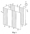
- Figure 1 is a perspective view of one retroreflective article 10 according to the present invention that includes a front surface 20 and a back surface 30 located opposite the front surface 20. Light 40 from light source 42 is incident on front surface 20 of the retroreflective article 10.
- Back surface 30 includes a plurality of retroreflective areas 32 that are designed to retroreflect light incident on them from the front surface 20 back towards the front surface 20 of the retroreflective article 10.
- a separation area 34 is located between each pair of adjacent retroreflective areas 32 on retroreflective article 10.
- the retroreflective areas 32 and the intervening separation areas 34 are columnar in shape, generally aligned with axis 12, and provided in a repeating pattern across the back surface 30. It will, however, be understood that the retroreflective areas 32 and separation areas 34 on the back surface 30 may be provided in irregular shapes and/or in non-repeating patterns.
- the separation areas 34 can provide a variety of optical effects.
- the separation areas 34 may transmit incident light, they may absorb incident light, they may be specularly reflective, diffusely reflective or retroreflective.
- the separation areas may exhibit two or more different optical properties, e.g., they may include absorptive and transmissive portions or other combinations.
- each of the separation areas 34 is retroreflective, it is preferred that they exhibit retroreflection that is, in some respect, different from the retroreflection exhibited by the retroreflective areas 32.
- a difference in retroreflection is a change in the brightness or intensity of the light retroreflected from the separation areas 34 as compared to the light retroreflected from the retroreflective areas 32.
- Another example of a difference in retroreflection is a change in the color of the light retroreflected from the separation areas 34 as compared to the color of light retroreflected from the retroreflective areas 32.
- Yet another difference could be in the entrance angularity or observation angularity of the retroreflective structures in the retroreflective areas 32 as compared to the separation areas 34.
- the front surface 20 of the retroreflective article 10 includes a plurality of first areas 22 and a plurality of second areas 24.
- the second areas 24 preferably differ from the first areas 22 in that they transmit a different amount of light through the front surface 20.
- different amount of light we mean that the second areas 24 transmit a different amount of light based on overall light intensity, wavelength(s), polarization, or some other characteristic.
- the amounts of light transmitted are determined relative to the amount of the light transmitted through the first areas 22 on the front surface 20.
- the first areas 22 may be smooth and clear such that they transmit substantially all normally (or near normally) incident light, while the second areas 24 absorb nearly all of the light incident on them.
- the first areas 22 may be transmissive, while the second areas 24 are reflective, i.e., they reflect a substantial portion of incident light.
- the first areas 22 may transmit light of all polarization orientations while the second areas may be provided with a polarizing film that reflects or absorbs a substantial amount of light having one polarization orientation while transmitting light with the orthogonal polarization orientation.
- the second areas 24 may be provided with a filter that absorbs light having one particular range of wavelengths while the first areas 22 transmit light having any visible wavelength.
- the first and second areas 22/24 may exhibit different colors such that the retroreflective article 10 exhibits different color retroreflected light based on the approach angle of the light.
- the second areas 24 may exhibit one or more optical properties selected from the group of: absorption, diffuse transmission, partial transmission, diffuse reflection, specular reflection, and retroreflection.
- the amount of light transmitted through the second areas 24 to the retroreflective areas 32 on the back surface 30 is different in some respect than the amount of light transmitted through the first areas 22 that is incident on the retroreflective areas 32 of the back surface 30. It is the differences in the amounts of light transmitted by the different areas on the front surface 20, when combined with the different retroreflective areas 32 and separation areas 34 on the back surface 30 that provides the modulating retroreflection from retroreflective articles according to the present invention.
- the first and second areas 22/24 on the front surface 20 of the retroreflective article 10 are preferably arranged relative to the retroreflective areas 32 and the separation areas 34 on the back surface 30 such that a substantial portion of light incident on the first areas 22 of the front surface 20 at a first angle is transmitted through the first areas 22 of the front surface 20 to the retroreflective areas 32 on the back surface 30 where the light is retroreflected back through the first areas 22 on the front surface 20.
- a substantial portion of the light incident on the first areas 22 of the front surface 20 at the second angle is transmitted through the first areas 22 on the front surface 20 to the separation areas 34 on the back surface 30.
- Between the first and second angles lies a range of approach angles in which a portion of the light transmitted through the first surfaces 22 is incident on the retroreflective areas 32 and a portion of the light transmitted through the first surfaces 22 is incident on the separation areas 34.
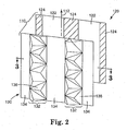
- the retroreflective article 110 depicted there includes a front surface 120 and a back surface 130.
- the front surface 120 preferably includes transmissive first areas 122 and second areas 124 that, in this embodiment, absorb substantially all of the light incident on them.
- the back surface 130 of the retroreflective article I 10 includes both retroreflective areas 132a-132d (collectively referred to as retroreflective areas 132), as well as separation areas 134a-134d (collectively referred to as separation areas 134).
- the retroreflective areas 132 and separation areas 134 are preferably arranged in columns that are generally aligned with the axis. 112 (see Figure 2).
- the retroreflective areas 132 preferably include a plurality of retroreflective structures 136.
- the preferred retroreflective structures 136 are cube corner elements, although it will be understood that the retroreflective areas 132 could include other retroreflective structures including, but not limited to retroreflective beads or spheres, conical retroreflective elements, and combinations of different retroreflective structures.
- the separation areas 134 in the retroreflective article 110 are preferably either transmissive or absorptive, such that light incident on separation areas 134 from the front surface 120 either exits the article 110 or is absorbed.
- the result of either transmissive or absorptive separation areas 134 is that, for light incident on a transmissive first area 122 on the front surface 120, the retroreflective article 110 would exhibit retroreflection only when the approach angle of the light was such that it was incident on one of the retroreflective areas 132 on the back surface 130. In those instances where the approach angle of the light was such that substantially all of the light was transmitted through the first areas 122 to one of the separation areas 134 on the back surface 130, the article 110 would exhibit no retroreflection. Light incident on the second areas 124 of the front surface would be absorbed with substantially none of the light being transmitted.
- Figure 3 includes a series of rays 140, 150, 160 and 170 to illustrate operation of the invention. It will be understood that refraction of the light passing through the front surface 120 will be ignored for the purposes of the following discussion.
- Ray 140 approaches the front surface 120 of the retroreflective article 110 parallel to the normal axis 114. Ray 140 is transmitted through the first area 122 and is incident on retroreflective area 132a on the back surface 130, where it is retroreflected back again.
- Ray 150 is incident on the first area 122 of the front surface 120 at an angle ⁇ with respect to the normal axis 114 where it is transmitted to retroreflective area 132b on the back surface 130. Ray 150 is then retroreflected back through the first area 122 on the front surface 120 of the retroreflective article 110.
- Ray 160 is incident on the first area 122 at an angle ⁇ with the normal axis 114, and is transmitted through the first area 122 towards retroreflective area 132c on the back surface 130, where it is retroreflected back again.
- Ray 170 is incident on one of the second areas 124 on the front surface 120 where it is absorbed such that substantially none of the light is retroreflected back along the path it followed when approaching the retroreflective article 110.
- ray 140 illustrates a "zero order" retroreflection, i.e., retroreflection from the retroreflective area 132a located directly across from the first area 122 along the normal axis 114.
- Ray 150 illustrates "first order” retroreflection, i.e., retroreflection from a retroreflective area 132b offset by one from the retroreflective area 132a located directly across from the first area 122.
- ray 160 illustrates "second order" retroreflection, i.e., retroreflectioll from a retroreflective area 132c offset by two from the retroreflective area 132a located directly across from the first area 122.
- article 110 From the above discussion of article 110, it can be seen that as the light was swept through a range of approach angles, the light would be retroreflected at some angles and not retroreflected at other angles and that those conditions would alternate through the range of angles. The end result is that, where the light source and the retroreflective article 110 were moving relative to each other such that the approach angle of the light on the front surface 120 changes, the article 110 would exhibit modulating or flashing retroreflection.
- retroreflective article 110 Another variation on the retroreflective article 110 is that shifting the spatial relationship between the areas on the front and back surfaces 120 and 130 will cause a change in the angles at which the retroreflective article 110 will retroreflect light.
- the centers of the retroreflective areas 132 are aligned with the centers of the first areas 122. It will be understood that it would be possible to shift the pattern of retroreflective areas 132 and separation areas 134 on the back surface 130 relative to the first and second areas 122/124 on the front surface and that such a variation would affect the angles at which incident light would be retroreflected or not retroreflected by the retroreflective article 110.
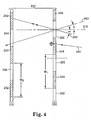
- Figure 4 depicts another embodiment of a retroreflective article 210 according to the present invention.
- the retroreflective article 210 includes a front surface 220 and a back surface 230.
- the front surface 220 of the article 210 includes first areas 222 and second areas 224.
- the first areas 222 specularly transmit a substantial portion of incident light while the second areas 224 diffusely transmit light.
- the first areas 222 and second areas 224 are preferably generally columnar and provided in a repeating pattern.
- the back surface 230 of retroreflective article 210 includes retroreflective areas 232 and separation areas 234.
- the retroreflective areas 232 and separation areas 234 are preferably arranged in columns that are generally aligned with the axis 212.
- the separation areas 234 in the retroreflective article 210 are preferably either transmissive or absorptive, such that light incident on separation areas 234 from the front surface 220 either exits the article 210 or is absorbed.
- the result of either transmissive or absorptive separation areas 234 is that, for light incident on a transmissive first area 222 on the front surface 220, the retroreflective article 210 would exhibit retroreflection only when the approach angle of the light was such that it was incident on one of the retroreflective areas 232 on the back surface 230. In those instances where the approach angle of the light was such that substantially all of the light was transmitted through the first areas 222 to one of the separation areas 234 on the back surface 230, the article 210 would exhibit no retroreflection.
- Figure 4 includes rays 240, 250 and 260 to illustrate operation of the retroreflective article 210. It will be understood that refraction of the light passing through the front surface 220 will be ignored for the purposes of the following discussion.
- Ray 240 approaches the front surface 220 of the retroreflective article 210 at an angle ⁇ with respect to normal axis 214. Ray 240 is transmitted through the first area 222 and is incident on one of the retroreflective areas 232 on the back surface 230, where it is retroreflected back again.
- Ray 250 is incident on the first area 222 of the front surface 220 at an angle ⁇ with respect to the normal axis 214 where it is transmitted to one of the separation areas 234 on the back surface 230. Ray 250 is transmitted through the separation surface 234 as depicted and, thus, is not returned to the front surface 220.
- Ray 260 is incident on one of the second areas 224 on the front surface 220 where it is diffusely transmitted such that substantially none of the light is retroreflected back along the path it followed when approaching the retroreflective article 210.
- the retroreflective article 210 of Figure 4 also exhibits another relationship between the first and second areas 222/224 on the front surface 220 and the retroreflective areas 232 and separation areas 234 on the back surface 230, namely that the retroreflective article 210 exhibits equal pitch between the different areas on the two surfaces.
- the pitch is represented by the width of the different areas on each of the two surfaces 220 and 230.
- Each pair of adjacent first and second surfaces 222/224 represents one group on the front surface 220 with a width w 1 that defines the pitch of the front surface 220.
- the pitch of the back surface 230 is defined by w 2 which includes the width of one of the retroreflective areas 232 combined with the width of an adjacent separation area 234.
- the pitch defined by the width of the first and second areas 222/224 should be large enough such that the diffractive effects of such a structure do not dominate the optical characteristics of the retroreflective article 210.
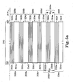
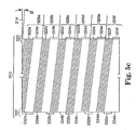
- Figures 5a-5c illustrate the effects of a difference in pitch between the front surface 320 and back surface 330 for a retroreflective article 310 where w 1 ' is not equal to w 2 ' (see Figure 5a).
- Figure 5a illustrates the effect on normal light
- Figures 5b and 5c illustrate the effects on light incident at angles off of the normal axis of ⁇ and ⁇ , respectively.
- the front surface 320 includes six pairs of first and second areas 322/324. Each pair of first and second areas 322/324 will be referred to as a front cell 326.
- the front surface 320 includes six front cells 326a-326f (referred to collectively as front cells 326).
- the back surface 330 includes only five pairs of retroreflective areas 332 and separation areas 334 (which for the purposes of this discussion will be assumed to absorb substantially all light incident on them). Each pair of retroreflective areas 332 and separation areas 334 will be referred to as a back cell 336. As a result, the back surface 330 includes live back cells 336a-336e (referred to collectively as back cells 336).
- the retroreflective areas 332 on the top and bottom of the depicted article 310 are aligned with the along the normal axis 314 with the first areas 322 on the top and bottom of the depicted retroreflective article 310, with the intervening retroreflective areas 332 being misaligned with the first areas 322 on the front surface 320.
- w 1 ': w 2 ' that is closer to unity than depicted in Figures 5a-5c
- the visual effect for an observer viewing the front surface 320 of the retroreflective article 310 along its normal axis will be the appearance of two bright bands of retroreflection at the top and bottom of the article 310 corresponding to the location of front cells 326a and 326f. These bright bands of retroreflection are depicted as white (i.e., unshaded) in Figure 5aa. Moving towards the center of the article 310, two bands of lesser brightness will appear next to both of the bright bands of retroreflection, with the areas of lesser brightness corresponding to front cells 326b and 326e. These intermediate or lesser brightness bands are cross-hatched in Figure 5aa.
- Figure 5b illustrates the effect of the retroreflective article 310 on light incident on front surface 320 at an angle of ⁇ with the normal axis 314 of the retroreflective article 310. Only a portion of the light incident on the first areas 322a, 322d, and 322f at angle ⁇ will be transmitted to the retroreflective areas 332a, 332c, and 332e (respectively). As a result, only a portion of the light incident on the first areas 322a, 322d, and 322f at angle ⁇ will be retroreflected. Substantially none of the light incident on the first areas 322b and 322c at angle ⁇ will be transmitted to a retroretlective area 332.
- substantially none of the light incident on the first areas 322b and 322c at angle ⁇ will be retroreflected.
- Substantially all of the light incident on first area 322e at angle ⁇ will be transmitted to the rctruretlective area 332d.
- substantially all of the light incident on first area 322e at angle ⁇ will be retroreflected.
- the visual effect for an observer viewing the front surface 320 of the retroreflective article 310 at an angle of ⁇ relative to the normal axis 314 will be the appearance of a single bright band of retroreflection corresponding generally to the location of front cell 326e.
- This bright band of retroreflection is depicted as white (i.e., unshaded) in Figure 5bb.
- the areas generally corresponding to front cells 326a, 326d, and 326f will appear as bands of lesser brightness relative to the fully retroreflected light from front cell 326e. These intermediate or lesser brightness bands are cross-hatched in Figure 5bb.
- the front cells 326b and 326c would return substantially none of light incident on article 310 at the angle ⁇ and, as a resalt, that area of the article 310 would appear dark to an observer viewing the article 310 at that angle.
- the cells with no retroreflection are depicted as solid black in Figure 5bb.
- Figure 5c illustrates the effect of the retroreflective article 310 on light incident on front surface 320 at an angle of ⁇ with the normal axis 314 of the retroreflective article 3 10, where the absolute value of ⁇ is greater than the absolute value of angle ⁇ depicted in Figure 5b.
- Substantially all of the light incident at the angle ⁇ on first area 322d will be transmitted to the retroreflective area 332c.
- substantially all of the light incident on first area 322d at that angle will be retroreflected. Only a portion of the light incident on the first areas 322c and 322e at angle ⁇ will be transmitted to the retroreflective areas 332b and 332d (respectively).
- the visual effect for an observer viewing the front surface 320 of the retroreflective article 310 at an angle of ⁇ relative to a normal axis will be the appearance of a single bright band of retroreflection generally corresponding to the location of front cell 326d.
- This bright band of retroreflection is depicted as white (i.e., unshaded) in Figure 5cc.
- the areas generally corresponding to front cells 326c and 326e will appear as bands of lesser brightness relative to the fully retroreflected light from front cell 326d. These intermediate or lesser brightness bands are cross-hatched in Figure 5cc.
- the front cells 326a, 326b and 326f would return substantially none of the light incident on article 310 at the angle ⁇ and, as a result, those areas of the article 310 would appear dark to an observer viewing the article 310 at that angle.
- the cells with no retroreflection are depicted as solid black in Figure 5cc.
- That relative motion may be useful in some applications in which the areas of brightness can appear to move relative to, e.g., the driver in a vehicle moving past the retroreflective article 310 because that movement causes the angle of incidence for light from the vehicle's lights as well as the observer (i.e., driver) to move relative to the normal axis of the retroreflective article 310.
- the retroreflective area 340 can provide a frame of reference for the light retroreflected from the front cells 326. Using that frame of reference will assist observers in discerning the shifting retroreflection from the front cells 326 of the retroreflective article 310.
- the width of the various features on the retroreflective articles 210 and 310 is measured substantially transverse to the axis along which the preferably columnar first and second areas, retroreflective areas, and separation areas are generally aligned.
- the separation areas 334 in the retroreflective article 310 are described above as being absorptive, it should be understood that the separation areas may, instead, have other optical characteristics.
- the separation areas 334 are transmissive
- the first areas 322 that transmit all or a portion of the light incident on them to the separation areas 334 may appear dark or of reduced brightness relative to the first areas 322 transmitting substantially all of the incident light to one of the retroreflective areas 332.
- the transmissive areas may allow for the viewing of a surface or image located proximate the back surface 330 of the retroreflective article 310.
- the bands of retroreflection returned from the retroreflective areas 332 through first areas 322 may be separated by bands of different colored retroreflection where the separation areas 334 include retroreflective structures that retroreflect light with one or more different optical characteristics from the light retroreflected from the retroreflective areas 332 as discussed above.
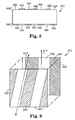
- FIGS. 6-8 depict another embodiment of retroreflective articles according to the present invention.
- the retroreflective article 410 includes a front surface 420 and a back surface 430.
- the various embodiments of the present invention described above include first and second areas on their front surfaces where different transmission properties of the areas on the front surface are important to operation of the retroreflective article.
- the retroreflective article 410 relies on different reflective properties of the areas on the front surface 420 and a back surface 430 that includes retroreflective areas 432 and separation areas 434 to provide modulating retroreflection.
- optical window 414 which is preferably substantially transmissive. It is preferred that the front and back surfaces 420 and 430 are generally planar. It is also preferred that the front and back surfaces 420 and 430 are generally parallel to each other. Furthermore, it is preferred that the end surface 415 extend substantially between the front and back surfaces 420 and 430.
- the front surface 420 includes first areas 422 that preferably substantial portions of the light incident on them and second areas 424 that reflect substantially less light incident on them than is reflected from the first areas 422.
- the optical properties of the first and second areas 422/424 can differ in one or more of the following: absorption, reflection, partial reflection, retroreflection, reflection angle, transmission, color, polarization, etc.
- the retroreflective areas 432 preferably include a plurality of retroreflective structures, typically cube corner elements, although it will be understood that the retroreflective areas 432 could include other retroreflective structures such as retroreflective beads or spheres, conical retroreflective structures and other retroreflective structures.
- the separation areas 434 can provide a variety of optical effects as described below in more detail.
- the preferred retroreflective article 410 includes reflective separation areas 434.
- first and second areas 422/424 are arranged in columns that are generally aligned with the axis 412.
- the retroreflective areas 432 and separation areas 434 on the back surface 430 are also preferably arranged in columns that are generally aligned with the axis 412.
- Figures 7 and 7a illustrate the paths of two rays of light 440 and 460 that enter retroreflective article 410 through optical window 414.
- the separation areas 434 are specularly reflective.
- Ray 440 enters retroreflective article 410 through optical window 414 where it is transmitted towards one of the reflective first areas 422. From the first area 422, ray 440 is specularly reflected towards one of the separation areas 434. At the separation area 434, the ray 440 is reflected (either by total internal reflection or with a reflective material) towards the end surface 415 of the retroreflective article 410.
- end surface 415 is preferably retroreflective, i.e., it retroreflects light incident upon it.
- ray 440 is retroreflected from the end surface 415 back towards the separation area 434 where it is reflected back towards the first area 422 on front surface 420.
- ray 440 is reflected back towards optical window 414 where it is retroreflected from the retroreflective article 410.
- Ray 460 enters retroreflective article 410 at point 470 on optical window 414 where it is transmitted towards one of the reflective first areas 422 on front surface 420. From the first area 422, ray 460 is specularly reflected towards one of the retroreflective areas 432 on back surface 430. As a result, ray 460 is retroreflected back towards the first area 422 on the front surface 420. At the front surface 420, ray 460 is reflected back towards the optical window 414 where it exits the retroreflective article 410 and is thus retroreflected. Because ray 460 is reflected to one of the retroreflective areas 432 on the back surface 430, it does not continue on to the end surface 415 as does ray 440. Rather, ray 460 is returned from its point of incidence on the retroreflective area 432 as seen in Figures 7 and 7a.
- the light retroreflected from the retroreflective areas 432 on the back surface 430 be distinguishable (to an observer) from light retroreflected from the end surface 415 of the retroreflective article 410.
- a difference in retroreflection is a change in the brightness or intensity of the light retroreflected from the end surface 415 as compared to the light retroreflected from the retroreflective areas 432.
- Another example of a difference in retroreflection is a change in the color of the light retroreflected from the end surface 415 as compared to the color of light retroreflected from the retroreflective areas 432.
- Other variations in retroreflected light are described above with respect to the retroreflective areas and separation areas on other illustrative retroreflective articles.
- the separation areas 434 in the retroreflective article 410 could be transmissive or absorptive, such that light incident on separation areas 434 from the front surface 420 either exits the article 410 through back surface 430 or is absorbed.
- the result of either transmissive or absorptive separation areas 434 is that, for light entering the article 410 through window 414, the retroreflective article 410 would exhibit retroreflection to an observer (not shown) viewing the window 414 of the retroreflective article 410 along or near to the path of the incident light only when the reflective front surface 420 reflects the incident light to the retroreflective areas 432.
- Retroreflective article 410 may be particularly well-suited for use as a pavement marker, i.e., an object adapted for placement on a roadway to mark lanes, crosswalks, etc. It will, however, be understood that retroreflective articles similar to that depicted in Figures 6-8 may find other applications as well.
- Figure 9 illustrates another variation in retroreflective articles according to the present invention.
- the first areas 522 and second areas 524 on the front surface 520 lie in columns that are generally aligned along a first axis 512.
- the back surface 530 preferably includes retroreflective areas 532 and separation areas 534 that are located in alternating columns aligned generally with second axis 514.
- the first and second axes 512/514 are not parallel with each other.
- the optical effects provided by orienting the first and second areas 522/524 on the front surface 520 "off-axis" with respect to the retroreflective areas 532 and separation areas 534 of the back surface 530 is that the retroreflective article 510 will exhibit areas that are retroreflective for light of a given approach angle and areas that are not retroreflective (or are retroreflective in a distinguishable manner as described above).
- the differences can be attributed to the transmission of light to either retroreflective areas or the separation areas depending on the relationship between the first and second areas 522/524 on the front surface 520 and the retroreflective areas and separation areas on the back surface 530.
- retroreflective articles includes front and back surfaces 620 and 630 that are not parallel to each other.
- the optical effect of orienting the front and back surfaces 620 and 630 in a non-parallel arrangement is that the pattern retroreflected from the front surface 620 of the retroreflective article 610 will appear as moiré effect. If the pitch of the various areas on both the front and back surfaces 620 and 630 are equal, then the observed light would revert back to on/off retroreflective flashing when the front and back surfaces 620 and 630 were oriented parallel to each other (assuming that the light incident on the separation areas was not returned to a viewer located along a path on or near the path of the incident light).
- the non-parallel orientation between the first and back surfaces could be accomplished using one or two separate bodies. If the surfaces 620 and 630 were located on one unitary body, e.g., a sheet, then deflection of the sheet from a planar status could effect a change in the retroreflection pattern. This effect could be useful in connection with, e.g., alignment mechanisms, temperature sensing, pressure sensing, and other situations in which deflection could be an indication of a change in some physical property.
- Figure 11 depicts yet another retroreflective article 710 according to the present invention in which the relative widths of the retroreflective areas 732 and the separation areas 734 can have an effect on the optical performance of the retroreflective article 710.
- the width of the retroreflective areas and separation areas of the retroreflective articles thus far described have been substantially equal.
- the width w rr of the retroreflective areas 732 is greater than the width w s of the separation areas 734, i.e., the retroreflective areas 732 occupy more of the surface area of the back surface 730 than the separation areas 734.
- the width, w f , of a pair of adjacent first and second areas 722/724 on the front surface 720 is substantially equal to the width w b of an adjacent pair of one retroreflective area 732 and a separation area 734.
- Figure 11 includes a first set of rays 740a, 740b, 740c, and 740d (collectively referred to as "rays 740"), all of which approach the front surface 720 of the retroreflective article 710 parallel to the normal axis 780.
- Rays 740a and 740b are transmitted through one of the transmissive first areas 722 to one of the retroreflective areas 732 on the back surface 730 of the retroreflective article 710.
- rays 740a and 740b are retroreflected on substantially the same path along which they entered the article 710.
- the optical performance of the retroreflective article 710 is similar to many of the retroreflective articles described above.
- Rays 740c and 740d are incident on one of the second areas 724 where they are, in this embodiment, absorbed.
- a second set of rays 750a, 750b, 750c, and 750d are also depicted in Figure I 1 and approach the front surface 720 of retroreflective article 710 at an angle ⁇ with respect to the normal axis 780 of retroreflective article 710.
- Rays 750a and 750b enter the retroreflective article 710 through one of the transmissive first areas 722 at the same angle, but they are not both transmitted to a retroreflective area 732. Instead, ray 750a is transmitted to the retroreflective area 732 as depicted in Figure 11 while ray 750b is transmitted to the separation area 734 and transmitted out of the retroreflective article 710.
- Rays 750c and 750d are incident on one of the second areas 724 where they are absorbed. As a result, a reduced amount of the light incident on the front surface 720 of the retroreflective article 710 at angle ⁇ will be retroreflected.
- Figure 12 The effect of varying the percentage of the back surface occupied by retroreflective areas as compared to separation areas is graphically illustrated in Figure 12. For the purposes of comparison, it will be assumed that light transmitted to one of the separation areas is absorbed, transmitted, or otherwise affected such that it is not returned to an observer located on or near the path along which the light incident on the retroreflective article.
- the horizontal axis in Figure 12 is representative of various approach angles for the incident light while the vertical axis is indicative of the intensity of the returned light.
- Line 760 in Figure 12 represents the optical performance of a retroreflective article in which the retroreflective areas are substantially equal in width to the separation areas and in which the pitch of the pattern of areas on the front surface of the retroreflective article is substantially equal to the pitch of the retroreflective areas and separation areas on the back surface.
- the intensity of the light returned along the path of the incident light i.e., retroreflected
- line 760 varies regularly from a maximum to zero as the approach angle of the incident light changes.
- FIG. 12 represents the optical performance of retroreflective article 710 in which the retroreflective areas are three times as wide as the separation areas.
- the result on the intensity of the incident light retroreflected from the article 710 over a range of approach angles varies.
- the retroreflective article 710 would not appear to flash on and off as the incident light and an associated observer approached the retroreflective article 710 at a changing angle (e.g., a driver approaching the retroreflective article 710 not along its normal axis).
- the retroreflective article 710 would, instead, appear to modulate, pulsate or vary in intensity or brightness as the approach angle varied over the range of angles depicted in Figure 12.
- Figures 11 and 12 can also be used to discuss another feature of the retroreflective articles according to the present invention, i.e., the ability to vary the flash rate of the retroreflective articles. Where all other variables are equal between two retroreflective articles according to the present invention, the retroreflective article that has a larger spacing between the front and back surfaces will exhibit a higher flash rate. By higher flash rate, we mean that the intensity of the light returned from a "thicker" retroreflective article will reach the maximum value more often over a given range of approach angles. With reference to Figure 12, the peaks in lines 760 or 770 will be spaced closer for a thicker retroreflective article.
- Thickness of a retroreflective article for these purposes is defined as the distance between the front surface and the back surface and thus applies to retroreflective articles that are encompassed by a single body, as well as those in which the first and back surfaces are provided on separate bodies.
- Figure 13 depicts another embodiment of a retroreflective article 910 according to the present invention in which the front surface 920 includes transmissive first areas 922 and second areas 924 that transmit a different amount of light, e.g., the second areas 924 are absorptive, reflective, etc.
- the back surface 930 includes more than two different areas that exhibit more than two different optical properties.
- the retroreflective article 910 includes three different retroreflective areas 934a, 934b, and 934c (collectively referred to as retroreflective areas 934).
- the different retroreflective areas 934 preferably exhibit different optical characteristics such as different colors, different intensities, etc.
- the retroreflective areas 934 are provided in a repeating array across the back surface 930. It will be understood that more than three different retroreflective areas 934 could be provided and that the back surface 930 could also include areas that are transmissive, absorptive, or reflective (specularly or diffusely) in combination with one or more different retroreflective areas.
- the light will strike different retroreflective areas 934 on the back surface 930, thereby providing different optical effects based on the optical characteristics of the retroreflective area or areas 934 on which the light is incident.
- the retroreflective articles according to the present invention can take the form of sheeting, films, and bodies having a rigidity not otherwise associated with sheetings or films.
- Retroreflective articles according to the present invention can be manufactured by replication using molds formed by many different methods, including those typically referred to as pin bundling and direct machining. Molds manufactured using pin bundling are made by assembling together individual pins, each of which have an end portion shaped with the desired features of the retroreflective article. Examples of pin bundling are described in, e.g., U.S. Patent No. 3,926,402 to Heenan et al. , and United Kingdom Patent Nos. 423,464 and 441,319 to Leray .
- the direct machining technique sometimes referred to as ruling, involves cutting portions of a substrate to create a pattern of grooves that intersect to form retroreflective structures.
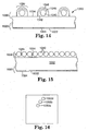
- the retroreflective article 1010 includes a front surface 1020 including different areas such as first and second areas 1022 and 1024 as described above.
- the back surface 1030 of the retroreflective articles 1010 includes a plurality of retroreflective areas 1032 and separation areas 1034.
- the retroreflective areas 1032 of the retroreflective article 1010 each include a plurality of retroreflective beads 1040 located in a binder 1042 that is bonded in place on the retroreflective article 1010.
- the beads 1040 may also be partially encapsulated by a spacer coat 1046 and reflective material 1048 as is well known to those skilled in the art.
- the binder 1042 is preferably cured by the use of light energy, e.g., ultraviolet light, as is well known.
- the retroreflective areas can be formed with the proper pitch using light energy in the process described below.
- the front surface 1020 could be formed in a suitable body 1012 such as a sheet or film in which the opposing surface 1014 was preferably smooth, i.e., planar.
- the opposing surface 1014 would then be coated over substantially its entire surface with a mixture of retroreflective beads 1040 and binder solution 1044 (see Figure 15).
- Light energy with the appropriate wavelength(s) required to cure the binder solution would then be directed at the front surface 1020 such that the light energy is transmitted through the body 1012 to the retroreflective areas 1032 on the finished retroreflective article 1010 (see Figure 14).
- the retroreflective beads 1040 will be retained in the cured binder 1042. In those areas where the light is not incident on the binder solution 1044, the beads 1040 and binder solution can be removed after the retroreflective areas 1032 have been cured.
- Application of any spacer coats and reflective materials can be accomplished by any suitable method.
- One significant advantage to this method is that the angle of the light energy used to cure the binder 1042 can be controlled, resulting in accurate formation of the retroreflective areas 1032 and separation areas 1034 relative to the position of the first and second areas 1022/1024 on the front surface 1020 of the retroreflective article 1010 for that angle of incident light. The result is that exposures at different angles can be used to create the desired retroreflective properties in the retroreflective article 1010.
- a bubble could appear to move from the bottom of the retroreflective article 1010 towards its top as illustrated in Figure 16.
- the incident light is presented at a first angle relative to the normal axis of the article 1010 corresponding the first angle at which the retroreflective article 1010 was exposed during manufacturing.
- the bubble 1050a would appear in the light retroreflected from the retroreflective article 1010.
- the incident light approached article 1010 along the normal axis, light could be retroreflected from an image of the bubble 1050b (while light would not be retroreflected from the first bubble 1050a).
- the retroreflective articles according to the present invention can be provided in macro- or micro-structured form (or a combination of both) and will typically exhibit the retroreflective properties discussed above in any form.
- Macro-structured articles can be provided from many different materials and in any appropriate dimensions depending on the intended application or use of the articles.
- Micro-structured articles will typically include small optical elements such as first areas, second areas, cube corners, facets, etc., sized such that the pitch of the features on the front surface of the retroreflective articles and the pitch of the features on the back surface of the retroreflective articles is about 0.03 inches (0.75 millimeters) or less, although in some instances it may be preferable to provide retroreflective articles in which the pitch of the features on the first and back surfaces is about 0.01 inches (0.25 millimeters) or less, and even more preferably about 0.005 inches (0.13) millimeters) or less. It may further be advantageous to use thin micro-structured sheeting incorporating the structures described above in some situations. The thin micro-structured sheeting may more preferably be flexible as described in, for example, U.S. Patent No. 4,906,070 (Cobb, Jr. ).
- Suitable materials for retroreflective articles according to the present invention can vary, although the articles will typically be manufactured from transparent materials that are dimensionally stable, durable, weatherable, and easily replicated in the desired configuration.
- suitable materials include glass, acrylics with an index of refraction of about 1.49 (e.g., PLEXIGLASS brand resin from Rohm & Haas Company), polycarbonates with an index of refraction of about 1.59, polyethylene based ionomers (e.g., SURLYN brand from E.I. DuPont de Nemours and Co., Inc.), polyesters, polyurethanes, and cellulose acetate butyrates.
- Other examples include reactive materials such as those taught in U.S. Patent Nos. 4,576,850 ; 4,582,885 ; and 4,668,558 .
- inventive retroreflective articles may be constructed according to the principles of U.S. Patent 5,450,235 where the cube-corner elements are made of a high modulus polymer and an overlapping body layer is made of a softer lower modulus polymer. Such a construction would also allow the inventive articles to be employed on articles of clothing as discussed below.
- Polycarbonates may be used because of their toughness, temperature stability, and relatively higher refractive index (about 1.59) which generally contributes to improved retroreflective performance over a wider range of entrance angles when using back surface reflectors.
- the higher index of refraction provides a larger index of refraction difference to enhance total internal reflection at interfaces with materials having lower indexes of refraction, e.g., air.
- materials with lower indices of refraction may offer an advantageous combination of properties.
- acrylics with an index of refraction of about 1.49 may offer an advantageous combination of properties.
- the materials used to form retroreflective articles may also include UV stabilizers or other additives to improve their weatherability, durability, toughness or any other desired property.
- the retroreflective article according to the present invention may include a reflective coating as needed to enhance their reflective properties.
- Such coatings could include a metal or a dielectric stack.
- any suitable coloring agent or agents may be used.
- coloring agent will be used herein to refer to any dye, colorant, pigment, etc. used to effect a visible color change in light exiting from the retroreflective articles according to the present invention.
- the retroreflective articles according to the present invention may be applied to a variety of substrates using mechanical methods such as sewing. In some applications, however, it may be desirable to secure the article to a substrate using adhesives, e.g., a pressure-sensitive adhesive, heat-activatable adhesive, or an ultraviolet radiation activated adhesive.
- adhesives e.g., a pressure-sensitive adhesive, heat-activatable adhesive, or an ultraviolet radiation activated adhesive.
- the substrate bearing the retroreflective article can be located on the outer surface of an article of clothing, enabling the retroreflective article to be displayed when the clothing is worn in its normal orientation on a person.
- the substrate may be, for example, a woven, knit or nonwoven fabric containing cotton, wool, flax, nylon, olefin, polyester, cellulose, rayon, urethane, vinyl, acrylic, rubber, spandex, and the like, or it could be made of leather or paper.
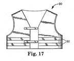
- FIG 17 illustrates a safety vest 90 displaying a retroreflective article 92 in the form of an elongated sheeting or strip.
- Safety vests are often worn by road construction workers and police officers to improve their visibility to oncoming motorists.
- a safety vest has been chosen for this illustration, articles of clothing including retroreflective articles according to the present invention may be provided in a variety of forms.
- article of clothing means an item of wearing apparel sized and configured to be worn or carried by a person.
Applications Claiming Priority (3)
| Application Number | Priority Date | Filing Date | Title |
|---|---|---|---|
| US09/019,108 US6045230A (en) | 1998-02-05 | 1998-02-05 | Modulating retroreflective article |
| EP98926032A EP1053490B1 (fr) | 1998-02-05 | 1998-06-03 | Article a retroreflexion modulable |
| EP04028579A EP1521105B1 (fr) | 1998-02-05 | 1998-06-03 | Procédé de fabrication d'un article rétroréfléchissant |
Related Parent Applications (1)
| Application Number | Title | Priority Date | Filing Date |
|---|---|---|---|
| EP04028579A Division EP1521105B1 (fr) | 1998-02-05 | 1998-06-03 | Procédé de fabrication d'un article rétroréfléchissant |
Publications (1)
| Publication Number | Publication Date |
|---|---|
| EP1712933A1 true EP1712933A1 (fr) | 2006-10-18 |
Family
ID=21791488
Family Applications (3)
| Application Number | Title | Priority Date | Filing Date |
|---|---|---|---|
| EP04028579A Expired - Lifetime EP1521105B1 (fr) | 1998-02-05 | 1998-06-03 | Procédé de fabrication d'un article rétroréfléchissant |
| EP06007894A Withdrawn EP1712933A1 (fr) | 1998-02-05 | 1998-06-03 | Article rétro-réflectif à rétro-réflexion modulable |
| EP98926032A Expired - Lifetime EP1053490B1 (fr) | 1998-02-05 | 1998-06-03 | Article a retroreflexion modulable |
Family Applications Before (1)
| Application Number | Title | Priority Date | Filing Date |
|---|---|---|---|
| EP04028579A Expired - Lifetime EP1521105B1 (fr) | 1998-02-05 | 1998-06-03 | Procédé de fabrication d'un article rétroréfléchissant |
Family Applications After (1)
| Application Number | Title | Priority Date | Filing Date |
|---|---|---|---|
| EP98926032A Expired - Lifetime EP1053490B1 (fr) | 1998-02-05 | 1998-06-03 | Article a retroreflexion modulable |
Country Status (10)
| Country | Link |
|---|---|
| US (1) | US6045230A (fr) |
| EP (3) | EP1521105B1 (fr) |
| JP (1) | JP4146084B2 (fr) |
| KR (1) | KR100558109B1 (fr) |
| CN (1) | CN1135406C (fr) |
| AU (1) | AU7796098A (fr) |
| CA (1) | CA2318425A1 (fr) |
| DE (2) | DE69829507T2 (fr) |
| TW (1) | TW425532B (fr) |
| WO (1) | WO1999040462A1 (fr) |
Families Citing this family (48)
| Publication number | Priority date | Publication date | Assignee | Title |
|---|---|---|---|---|
| US6282026B1 (en) | 1998-02-05 | 2001-08-28 | 3M Innovative Properties Company | Retroreflectors having two optical surfaces and varying retroreflectivity |
| US7667895B2 (en) * | 1999-07-08 | 2010-02-23 | Jds Uniphase Corporation | Patterned structures with optically variable effects |
| US20070195392A1 (en) * | 1999-07-08 | 2007-08-23 | Jds Uniphase Corporation | Adhesive Chromagram And Method Of Forming Thereof |
| US6761959B1 (en) * | 1999-07-08 | 2004-07-13 | Flex Products, Inc. | Diffractive surfaces with color shifting backgrounds |
| US7047883B2 (en) | 2002-07-15 | 2006-05-23 | Jds Uniphase Corporation | Method and apparatus for orienting magnetic flakes |
| US6987590B2 (en) * | 2003-09-18 | 2006-01-17 | Jds Uniphase Corporation | Patterned reflective optical structures |
| EP1849620B1 (fr) * | 2000-01-21 | 2016-03-23 | Viavi Solutions Inc. | Dispositifs de sécurité optiquement variables |
| US11768321B2 (en) | 2000-01-21 | 2023-09-26 | Viavi Solutions Inc. | Optically variable security devices |
| JP4053260B2 (ja) * | 2000-10-18 | 2008-02-27 | シャープ株式会社 | 有機エレクトロルミネッセンス表示素子 |
| US6931665B2 (en) * | 2001-07-30 | 2005-08-23 | 3M Innovative Properties Company | Vapor permeable retroreflective garment |
| US6692830B2 (en) * | 2001-07-31 | 2004-02-17 | Flex Products, Inc. | Diffractive pigment flakes and compositions |
| US6841238B2 (en) | 2002-04-05 | 2005-01-11 | Flex Products, Inc. | Chromatic diffractive pigments and foils |
| US7625632B2 (en) * | 2002-07-15 | 2009-12-01 | Jds Uniphase Corporation | Alignable diffractive pigment flakes and method and apparatus for alignment and images formed therefrom |
| US6749936B2 (en) | 2001-12-20 | 2004-06-15 | Flex Products, Inc. | Achromatic multilayer diffractive pigments and foils |
| US7934451B2 (en) * | 2002-07-15 | 2011-05-03 | Jds Uniphase Corporation | Apparatus for orienting magnetic flakes |
| US11230127B2 (en) | 2002-07-15 | 2022-01-25 | Viavi Solutions Inc. | Method and apparatus for orienting magnetic flakes |
| US20100208351A1 (en) * | 2002-07-15 | 2010-08-19 | Nofi Michael R | Selective and oriented assembly of platelet materials and functional additives |
| US8025952B2 (en) | 2002-09-13 | 2011-09-27 | Jds Uniphase Corporation | Printed magnetic ink overt security image |
| US7645510B2 (en) * | 2002-09-13 | 2010-01-12 | Jds Uniphase Corporation | Provision of frames or borders around opaque flakes for covert security applications |
| US9164575B2 (en) * | 2002-09-13 | 2015-10-20 | Jds Uniphase Corporation | Provision of frames or borders around pigment flakes for covert security applications |
| US7674501B2 (en) * | 2002-09-13 | 2010-03-09 | Jds Uniphase Corporation | Two-step method of coating an article for security printing by application of electric or magnetic field |
| US9458324B2 (en) | 2002-09-13 | 2016-10-04 | Viava Solutions Inc. | Flakes with undulate borders and method of forming thereof |
| US7550197B2 (en) * | 2003-08-14 | 2009-06-23 | Jds Uniphase Corporation | Non-toxic flakes for authentication of pharmaceutical articles |
| CA2541568C (fr) | 2005-04-06 | 2014-05-13 | Jds Uniphase Corporation | Dispositifs optiques a changement dynamique d'apparence (dacod) imprimes dans un champ magnetique mis en forme comprenant des structures de fresnel imprimables |
| AU2006202315B2 (en) * | 2005-06-17 | 2011-01-27 | Viavi Solutions Inc. | Covert security coating |
| CA2564764C (fr) * | 2005-10-25 | 2014-05-13 | Jds Uniphase Corporation | Structures optiques a motif avec fonction de securite amelioree |
| CA2570965A1 (fr) * | 2005-12-15 | 2007-06-15 | Jds Uniphase Corporation | Dispositif de securite a caracteristiques metameriques utilisant des flocons de pigments diffractifs |
| TWI437059B (zh) * | 2006-07-12 | 2014-05-11 | Jds Uniphase Corp | 壓印一經硬化及場配向之特效薄片之塗層及藉此形成之圖像 |
| US20080101759A1 (en) * | 2006-10-26 | 2008-05-01 | K Laser Technology, Inc. | Prism matrix with random phase structures |
| KR20090067654A (ko) * | 2007-12-21 | 2009-06-25 | 김봉주 | 재귀반사소자 및 이를 구비한 재귀반사체 |
| JP2009193069A (ja) | 2008-02-13 | 2009-08-27 | Jds Uniphase Corp | 光学的な特殊効果フレークを含むレーザ印刷用の媒体 |
| DE102008016813B4 (de) * | 2008-04-01 | 2021-08-12 | Tesa Scribos Gmbh | Holographischer Datenspeicher |
| US8425059B2 (en) | 2009-12-01 | 2013-04-23 | The Boeing Company | Low power retro-reflective communications system and method |
| USD665584S1 (en) * | 2010-03-05 | 2012-08-21 | Orafol Europe Gmbh | Retro-reflective sheeting with a corner cube surface pattern having angular corner cube circular regions |
| BR112013030706A2 (pt) | 2011-05-31 | 2016-12-06 | 3M Innovative Properties Co | métodos de fabricação de artigos microestruturados curados com padrão diferencialmente |
| CN103561927B (zh) | 2011-05-31 | 2016-07-27 | 3M创新有限公司 | 用于制备具有不连续的形貌特征的微结构化工具的方法以及由所述工具制造的制品 |
| IN2014MN01816A (fr) | 2012-01-12 | 2015-06-12 | Jds Uniphase Corp | |
| KR20140124824A (ko) * | 2012-02-06 | 2014-10-27 | 애버리 데니슨 코포레이션 | 방향 능동적 투사 |
| KR102200725B1 (ko) * | 2014-06-16 | 2021-01-12 | 미래나노텍(주) | 시트 성형용 몰드 제조 방법 및 시트 성형용 몰드 및 재귀반사 시트 |
| WO2016199902A1 (fr) * | 2015-06-12 | 2016-12-15 | 日本カーバイド工業株式会社 | Dispositif d'affichage d'image |
| WO2017156448A1 (fr) * | 2016-03-11 | 2017-09-14 | Mirraviz, Inc. | Profils de réflexion personnalisés pour une optimisation de système d'affichage rétro-réfléchissant |
| US11640019B2 (en) | 2016-11-22 | 2023-05-02 | 3M Innovative Properties Company | Spectrally selective retroreflective system |
| EP3582642A4 (fr) * | 2017-02-20 | 2021-01-13 | 3M Innovative Properties Company | Articles optiques et systèmes interagissant avec ceux-ci |
| US10723299B2 (en) | 2017-05-18 | 2020-07-28 | Srg Global Inc. | Vehicle body components comprising retroreflectors and their methods of manufacture |
| WO2019046403A1 (fr) * | 2017-08-29 | 2019-03-07 | Avery Dennison Corporation | Feuille rétroréfléchissante destinée à un système d'affichage basé sur un projecteur |
| US11001979B2 (en) | 2018-08-13 | 2021-05-11 | Vergence Automation, Inc. | Methods and apparatus for ultrawide entrance angle reflective articles for use with autonomous vehicle machine vision systems |
| US11762133B1 (en) | 2018-09-13 | 2023-09-19 | Vergence Automation, Inc. | Retroreflective materials and articles incorporating near-ideal total internal retroreflective elements |
| WO2021137644A1 (fr) * | 2019-12-31 | 2021-07-08 | 미래나노텍글로벌(주) | Feuille rétroréfléchissante et plaque d'immatriculation de véhicule utilisant celle-ci |
Citations (6)
| Publication number | Priority date | Publication date | Assignee | Title |
|---|---|---|---|---|
| US3877786A (en) * | 1973-06-28 | 1975-04-15 | Yankee Artists | Multicolored reflective article and its manufacture |
| EP0171252A2 (fr) * | 1984-08-03 | 1986-02-12 | Minnesota Mining And Manufacturing Company | Feuille transparente filigranée et sa méthode de fabrication |
| JPH02196653A (ja) * | 1989-01-26 | 1990-08-03 | Seibu Raito Internatl Kk | セル状再帰反射シート |
| EP0759448A1 (fr) * | 1995-08-21 | 1997-02-26 | Dainippon Printing Co., Ltd. | Composition de résine durcissable par radiation ionisante pour article optique, article optique, et source lumineuse plane |
| WO1997019820A1 (fr) * | 1995-11-28 | 1997-06-05 | Electrowatt Technology Innovation Ag | Porteur d'informations optiques |
| WO1997041465A1 (fr) * | 1996-04-30 | 1997-11-06 | Minnesota Mining And Manufacturing Company | Revetement retroreflechissant scintillant utilisant des elements pyramidaux |
Family Cites Families (47)
| Publication number | Priority date | Publication date | Assignee | Title |
|---|---|---|---|---|
| US752429A (en) * | 1904-02-16 | Prismatic illuminating structure | ||
| GB190908324A (en) * | 1908-10-14 | 1909-09-30 | Otis Angelo Mygatt | Improved Glassware. |
| US1128979A (en) * | 1912-06-01 | 1915-02-16 | Walter Hess | Stereoscopic picture. |
| US1475430A (en) * | 1922-02-27 | 1923-11-27 | Curwen John Spedding | Advertising device or toy |
| US1792731A (en) * | 1929-08-07 | 1931-02-17 | Richard M Craig | Display apparatus |
| US1987357A (en) * | 1932-01-08 | 1935-01-08 | William V Bergen | Reflector |
| GB423464A (en) * | 1932-12-31 | 1935-02-01 | Gustave Leray | Improvements in light reflectors |
| GB441319A (en) * | 1933-12-21 | 1936-01-16 | Gustave Leray | Improvements in or relating to light reflectors |
| US2268351A (en) * | 1938-08-25 | 1941-12-30 | Tanaka Nawokich | Means for presenting pictures in apparent three dimensions |
| US2432896A (en) * | 1945-03-12 | 1947-12-16 | Hotchner Fred | Retroreflective animation display |
| US3085473A (en) * | 1957-07-10 | 1963-04-16 | Saint Gobain | Sheets, bricks, blocks or similar articles made of transparent material, especially glass |
| US3085474A (en) * | 1957-07-10 | 1963-04-16 | Saint Gobain | Articles made of a transparent material such as glass sheets, bricks or blocks, and having variable transparency or coloration |
| US3712706A (en) * | 1971-01-04 | 1973-01-23 | American Cyanamid Co | Retroreflective surface |
| GB1422780A (en) * | 1972-04-14 | 1976-01-28 | Ass Eng Ltd | Retro-reflectors |
| US3830682A (en) * | 1972-11-06 | 1974-08-20 | Rowland Dev Corp | Retroreflecting signs and the like with novel day-night coloration |
| US3926402A (en) * | 1973-04-24 | 1975-12-16 | Amerace Corp | Pin having nonaligned cube axis and pin axis and bundle of such pins |
| US3975083A (en) * | 1974-07-24 | 1976-08-17 | Reflexite Corporation | Wide angle retroreflector assembly and method of making same |
| US4012115A (en) * | 1975-07-10 | 1977-03-15 | Qantix Corporation | Sawtooth shaped front screen |
| US4025159A (en) * | 1976-02-17 | 1977-05-24 | Minnesota Mining And Manufacturing Company | Cellular retroreflective sheeting |
| US4349598A (en) * | 1976-12-01 | 1982-09-14 | Minnesota Mining And Manufacturing Company | High incidence angle retroreflective material |
| US4576850A (en) * | 1978-07-20 | 1986-03-18 | Minnesota Mining And Manufacturing Company | Shaped plastic articles having replicated microstructure surfaces |
| US4668558A (en) * | 1978-07-20 | 1987-05-26 | Minnesota Mining And Manufacturing Company | Shaped plastic articles having replicated microstructure surfaces |
| US4582885A (en) * | 1978-07-20 | 1986-04-15 | Minnesota Mining And Manufacturing Company | Shaped plastic articles having replicated microstructure surfaces |
| US4447723A (en) * | 1981-09-03 | 1984-05-08 | Excellon Industries | Scanning beam reference employing a retroreflective code means |
| US4634220A (en) * | 1983-02-07 | 1987-01-06 | Minnesota Mining And Manufacturing Company | Directionally imaged sheeting |
| US4542449A (en) * | 1983-08-29 | 1985-09-17 | Canadian Patents & Development Limited | Lighting panel with opposed 45° corrugations |
| US4588258A (en) * | 1983-09-12 | 1986-05-13 | Minnesota Mining And Manufacturing Company | Cube-corner retroreflective articles having wide angularity in multiple viewing planes |
| US4650283A (en) * | 1984-08-03 | 1987-03-17 | Minnesota Mining And Manufacturing Company | Directionally imaged retroreflective sheeting |
| US4688894A (en) * | 1985-05-13 | 1987-08-25 | Minnesota Mining And Manufacturing Company | Transparent retroreflective sheets containing directional images and method for forming the same |
| US4708920A (en) * | 1985-09-16 | 1987-11-24 | Minnesota Mining And Manufacturing Company | Microlens sheet containing directional half-tone images and method for making the same |
| CA1267173A (fr) * | 1985-09-23 | 1990-03-27 | Thomas I. Bradshaw | Feuille portant une image directive dependant d'un contour et methode de fabrication de cette feuille |
| CA1279783C (fr) * | 1985-11-21 | 1991-02-05 | Minnesota Mining And Manufacturing Company | Pellicule mince et souple reflechissant integralement vers l'interieur |
| US4938563A (en) * | 1986-11-21 | 1990-07-03 | Minnesota Mining And Manufacturing Company | High efficiency cube corner retroflective material |
| US4726134A (en) * | 1986-11-21 | 1988-02-23 | Minnesota Mining And Manufacturing Company | Roadway sign |
| US4983436A (en) * | 1987-04-15 | 1991-01-08 | Minnesota Mining And Manufacturing Company | Retroreflective sheeting with backing film |
| US5066098A (en) * | 1987-05-15 | 1991-11-19 | Minnesota Mining And Manufacturing Company | Cellular encapsulated-lens high whiteness retroreflective sheeting with flexible cover sheet |
| GB8720923D0 (en) * | 1987-09-05 | 1987-10-14 | Emi Plc Thorn | Optical image rotators |
| US4895428A (en) * | 1988-07-26 | 1990-01-23 | Minnesota Mining And Manufacturing Company | High efficiency retroreflective material |
| US5122902A (en) * | 1989-03-31 | 1992-06-16 | Minnesota Mining And Manufacturing Company | Retroreflective articles having light-transmissive surfaces |
| US5050327A (en) * | 1989-11-17 | 1991-09-24 | Minnesota Mining And Manufacturing Company | Retroreflective sign having improved legibility |
| US5254390B1 (en) * | 1990-11-15 | 1999-05-18 | Minnesota Mining & Mfg | Plano-convex base sheet for retroreflective articles |
| ZA918849B (en) * | 1990-12-06 | 1992-08-26 | Minnesota Mining & Mfg | Articles exhibiting durable fluorescence |
| US5237449A (en) * | 1991-01-29 | 1993-08-17 | Nelson Optics Company, Inc. | Biased lenticular sign system |
| US5272562A (en) * | 1993-02-05 | 1993-12-21 | Minnesota Mining And Manufacturing Company | Cube-corner retroreflective articles |
| US5450235A (en) * | 1993-10-20 | 1995-09-12 | Minnesota Mining And Manufacturing Company | Flexible cube-corner retroreflective sheeting |
| US5471348A (en) * | 1994-05-13 | 1995-11-28 | Minnesota Mining And Manufacturing Company | Directed reflection optical device |
| US5814355A (en) * | 1996-04-30 | 1998-09-29 | Minnesota Mining And Manufacturing Company | Mold for producing glittering cube-corner retroreflective sheeting |
-
1998
- 1998-02-05 US US09/019,108 patent/US6045230A/en not_active Expired - Lifetime
- 1998-06-03 DE DE69829507T patent/DE69829507T2/de not_active Expired - Fee Related
- 1998-06-03 WO PCT/US1998/009523 patent/WO1999040462A1/fr active IP Right Grant
- 1998-06-03 KR KR1020007008431A patent/KR100558109B1/ko not_active IP Right Cessation
- 1998-06-03 JP JP2000530817A patent/JP4146084B2/ja not_active Expired - Fee Related
- 1998-06-03 CN CNB988134713A patent/CN1135406C/zh not_active Expired - Fee Related
- 1998-06-03 AU AU77960/98A patent/AU7796098A/en not_active Abandoned
- 1998-06-03 DE DE69834280T patent/DE69834280T2/de not_active Expired - Fee Related
- 1998-06-03 CA CA002318425A patent/CA2318425A1/fr not_active Abandoned
- 1998-06-03 EP EP04028579A patent/EP1521105B1/fr not_active Expired - Lifetime
- 1998-06-03 EP EP06007894A patent/EP1712933A1/fr not_active Withdrawn
- 1998-06-03 EP EP98926032A patent/EP1053490B1/fr not_active Expired - Lifetime
-
1999
- 1999-01-20 TW TW088100846A patent/TW425532B/zh not_active IP Right Cessation
Patent Citations (6)
| Publication number | Priority date | Publication date | Assignee | Title |
|---|---|---|---|---|
| US3877786A (en) * | 1973-06-28 | 1975-04-15 | Yankee Artists | Multicolored reflective article and its manufacture |
| EP0171252A2 (fr) * | 1984-08-03 | 1986-02-12 | Minnesota Mining And Manufacturing Company | Feuille transparente filigranée et sa méthode de fabrication |
| JPH02196653A (ja) * | 1989-01-26 | 1990-08-03 | Seibu Raito Internatl Kk | セル状再帰反射シート |
| EP0759448A1 (fr) * | 1995-08-21 | 1997-02-26 | Dainippon Printing Co., Ltd. | Composition de résine durcissable par radiation ionisante pour article optique, article optique, et source lumineuse plane |
| WO1997019820A1 (fr) * | 1995-11-28 | 1997-06-05 | Electrowatt Technology Innovation Ag | Porteur d'informations optiques |
| WO1997041465A1 (fr) * | 1996-04-30 | 1997-11-06 | Minnesota Mining And Manufacturing Company | Revetement retroreflechissant scintillant utilisant des elements pyramidaux |
Non-Patent Citations (1)
| Title |
|---|
| PATENT ABSTRACTS OF JAPAN vol. 014, no. 486 (M - 1038) 23 October 1990 (1990-10-23) * |
Also Published As
| Publication number | Publication date |
|---|---|
| WO1999040462A1 (fr) | 1999-08-12 |
| JP2002502985A (ja) | 2002-01-29 |
| KR20010040562A (ko) | 2001-05-15 |
| EP1521105A1 (fr) | 2005-04-06 |
| DE69829507D1 (de) | 2005-04-28 |
| DE69834280D1 (de) | 2006-05-24 |
| TW425532B (en) | 2001-03-11 |
| CN1284172A (zh) | 2001-02-14 |
| EP1053490A1 (fr) | 2000-11-22 |
| EP1521105B1 (fr) | 2006-04-19 |
| DE69829507T2 (de) | 2006-02-16 |
| JP4146084B2 (ja) | 2008-09-03 |
| KR100558109B1 (ko) | 2006-03-10 |
| CA2318425A1 (fr) | 1999-08-12 |
| DE69834280T2 (de) | 2007-04-12 |
| AU7796098A (en) | 1999-08-23 |
| EP1053490B1 (fr) | 2005-03-23 |
| CN1135406C (zh) | 2004-01-21 |
| US6045230A (en) | 2000-04-04 |
Similar Documents
| Publication | Publication Date | Title |
|---|---|---|
| US6045230A (en) | Modulating retroreflective article | |
| US6282026B1 (en) | Retroreflectors having two optical surfaces and varying retroreflectivity | |
| CA2293657C (fr) | Articles a retroreflexion sur deux axes | |
| CA2010201C (fr) | Articles retroreflechissant la lumiere | |
| US7703931B2 (en) | Two-sided corner-cube retroreflectors and methods of manufacturing the same | |
| AU701225B2 (en) | Encased retroreflective elements and method for making | |
| EP1756632B1 (fr) | Structures retroreflechissantes | |
| EP1151327B1 (fr) | Articles de formation d'images et procedes utilisant des elements retroreflechissants a deux axes | |
| US6935756B2 (en) | Retroreflective articles having moire-like pattern | |
| KR19990022404A (ko) | 부등변 베이스 삼각형을 갖는 역반사 입방체 코너 아티클 | |
| CA2222423C (fr) | Elements retroreflechissants encastres et procede de fabrication | |
| CA2536958A1 (fr) | Mthode ameliorant la visibilite d'un objet en utilisant des articles a retroreflexion sur deux axes |
Legal Events
| Date | Code | Title | Description |
|---|---|---|---|
| PUAI | Public reference made under article 153(3) epc to a published international application that has entered the european phase |
Free format text: ORIGINAL CODE: 0009012 |
|
| AC | Divisional application: reference to earlier application |
Ref document number: 1053490 Country of ref document: EP Kind code of ref document: P Ref document number: 1521105 Country of ref document: EP Kind code of ref document: P |
|
| AK | Designated contracting states |
Kind code of ref document: A1 Designated state(s): AT BE CH CY DE DK ES FI FR GB GR IE IT LI LU MC NL PT SE |
|
| AX | Request for extension of the european patent |
Extension state: AL LT LV MK RO SI |
|
| 17P | Request for examination filed |
Effective date: 20070316 |
|
| AKX | Designation fees paid |
Designated state(s): DE FR GB IT |
|
| GRAP | Despatch of communication of intention to grant a patent |
Free format text: ORIGINAL CODE: EPIDOSNIGR1 |
|
| STAA | Information on the status of an ep patent application or granted ep patent |
Free format text: STATUS: THE APPLICATION IS DEEMED TO BE WITHDRAWN |
|
| 18D | Application deemed to be withdrawn |
Effective date: 20090303 |