EP1711097B1 - Reinigungsmaschine - Google Patents
Reinigungsmaschine Download PDFInfo
- Publication number
- EP1711097B1 EP1711097B1 EP05704742A EP05704742A EP1711097B1 EP 1711097 B1 EP1711097 B1 EP 1711097B1 EP 05704742 A EP05704742 A EP 05704742A EP 05704742 A EP05704742 A EP 05704742A EP 1711097 B1 EP1711097 B1 EP 1711097B1
- Authority
- EP
- European Patent Office
- Prior art keywords
- cleaning machine
- machine according
- outer body
- adhering
- band
- Prior art date
- Legal status (The legal status is an assumption and is not a legal conclusion. Google has not performed a legal analysis and makes no representation as to the accuracy of the status listed.)
- Expired - Lifetime
Links
- 238000004140 cleaning Methods 0.000 title claims abstract description 81
- 239000002689 soil Substances 0.000 claims abstract description 7
- 239000000428 dust Substances 0.000 claims abstract description 6
- 239000002245 particle Substances 0.000 claims abstract description 5
- 238000003860 storage Methods 0.000 claims description 10
- 230000008878 coupling Effects 0.000 claims description 5
- 238000010168 coupling process Methods 0.000 claims description 5
- 238000005859 coupling reaction Methods 0.000 claims description 5
- 230000003068 static effect Effects 0.000 claims description 4
- 238000005096 rolling process Methods 0.000 claims description 3
- 230000000694 effects Effects 0.000 claims description 2
- 230000005611 electricity Effects 0.000 claims description 2
- 238000000605 extraction Methods 0.000 claims description 2
- 239000000835 fiber Substances 0.000 claims description 2
- 230000002787 reinforcement Effects 0.000 claims description 2
- 239000000126 substance Substances 0.000 claims 1
- 230000006870 function Effects 0.000 description 4
- 230000008901 benefit Effects 0.000 description 2
- 230000008859 change Effects 0.000 description 2
- 230000009471 action Effects 0.000 description 1
- 238000004026 adhesive bonding Methods 0.000 description 1
- 238000004891 communication Methods 0.000 description 1
- 230000000295 complement effect Effects 0.000 description 1
- 230000005484 gravity Effects 0.000 description 1
- 238000000034 method Methods 0.000 description 1
- 238000004804 winding Methods 0.000 description 1
Images



Classifications
-
- A—HUMAN NECESSITIES
- A47—FURNITURE; DOMESTIC ARTICLES OR APPLIANCES; COFFEE MILLS; SPICE MILLS; SUCTION CLEANERS IN GENERAL
- A47L—DOMESTIC WASHING OR CLEANING; SUCTION CLEANERS IN GENERAL
- A47L25/00—Domestic cleaning devices not provided for in other groups of this subclass
- A47L25/005—Domestic cleaning devices not provided for in other groups of this subclass using adhesive or tacky surfaces to remove dirt, e.g. lint removers
Definitions
- the present invention relates to cleaning machine, comprising a cylindrical outer body provided with an excentric driving device provided within said cylinder for excentric driving of the cylinder by a battery-operated electric motor, further a band- formed adhering means for adhering dust and other soil particles provided to be continuously fed to and from the outer surface of the outer body via a feed means arranged within the cylinder.
- JP 10262881 A Aikawa Kimiwaka disclosing a ball with outer tack means for adhering dust etc when driven by an excentrically arranged driving means driven by a battery - operated electrical motor.
- US 6343397 B1 relates to a cylindrical cleaning machine with a feed- and removably arranged tack paper, which is substantially as wide as the length of the cylinder. The driving is manual. Both of these machines provide a very limited function. The object of the present invention is thus to create a cleaning machine of the type mentioned introductorily, that is economic when used and that is functionally flexible.
- such a cleaning machine is primarily characteri - sed in that the cylindrical outer body is provided with a first and a second circumferential opening for feeding from and to of the tack means, provided at a distance from each other in the axial extension of the outer body, whereas the width of the tack means is substantially minor to said distance.
- the adhering means may be provided for pulsing roll- off extraction and releasing from a storage roll.
- the cleaning machine may be provided with sensing means for controlling the force, that loads a spring means, which controls the rolling in of the adhering means.
- the force to the spring means is transferred by a pendulum movement, achieved by an excentric axis.
- the loading and storage of the spring force is made in the same way as at a clock with spring for winding.
- the adhering means may consist of a finite band for adhering dust and soil particles by tacking, alternatively static electric adhesion.
- the band is provided with a tacking adhesion by double folding of these.
- the band may be provided with elongated fibre reinforcement in order to eliminate the risk for breakage.
- guide means such as ground recesses.
- the cylindrical outer body is provided with guide means, like recesses, preventing the band from changing direction laterally.
- the radius of at least one segment of the cylindrical outer body may be increased in relationship to the radius of the rest of the cylindrical outer surface.
- the cleaning machine may be provided with means for loading with static electricity when moving, a brush or the like.
- the means may be provided to act upon, that is to say rub the inside of the outer body during the movement of the cleaning machine.
- a loading unit belonging to the cleaning machine For loading of the battery there is a loading unit belonging to the cleaning machine. This is provided with means for coupling with corresponding means at the cleaning machine for loading current transfer. Per se this coupling may of course be performed manually, but it is also possible to provide the loading unit with means for automatic catching and coupling when the cleaning machine is within the action area of said means. The loading goes on until an indicator shows, that the loading has reached an upper limit.
- the cleaning machine may be provided with more or less advanced electric or electronic devices for controlling of its functions.
- these devices consist of a switch for starting of the movement of the cleaning machine.
- the cleaning machine may also be provided with a device for controlling the time for start/stop.
- it is provided with a means arranged to turn the poles of the feed current to the drive motor in order to exchange the moving direction of the cleaning machine at an obstacle/stop.
- the driving device of the cleaning machine is provided to drive the cleaning machine at varying speeds.
- the cleaning machine comprises a means for sensing the distance to an obstacle, and arranged to reduce the speed of the cleaning machine in the vicinity of the obstacle.
- the cleaning machine is provided with a computer with a programmable memory, which may be programmed with instructions for the activity of the cleaning machine.
- the cleaning machine is provided with means for coordinate determination, that is to say for determination of the position of the cleaning machine within the working area in question, whereas the memory of the computer is programmed with the coordinates for same in at least two dimensions, whereas it is provided to avoid programmed obstacles or already passed areas.
- the position determination may be carried out in different ways, e g be providing the cleaning machine with sensors for distance determination, measuring the distance to reference elements located within the working area according to known technique.
- the transfer of said instructions to the programmable memory may be carried out in different ways. Per se it would be possible to provide the cleaning machine with a set of buttons for direct programming, but this requires a design, that may be cumbersome and impractical.
- the transfer of said instructions from the control unit may be carried out via a line, connectable to the cleaning machine, or in that the control unit and the cleaning machine are provided with a transmitter and a receive, whereas the transfer of said instruction is performed wirelessly.
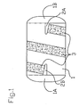
- a circular cylindrical outer body or mantle is marked by 1, provided with a first and a second opening 2A, 2B in the form of slits for feeding from and to of an adhering means 3.
- the openings are located in the vicinity of each its end of the outer body.
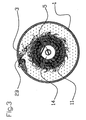
- the adhering means has the form of a relatively narrow band, which may be wound one or more turns around the outer body depending on the width of the band and the length of the outer body. In this case it is wound two turns around the outer body, from a storage roll 12 to a drawing roll 11 at a central axis 5, that also carries the driving device.
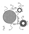
- the storage roll 12 is excentrically journalled on the central axis 5 (the figure is parted in figures 4- 6 for more clear illustration), at the opposite side of the driving device at level with the opening 2A, whereas at each turning and the excentric bearing the storage roll 12 moves diametrically and together with the drawing via the drawing roll 11 a feeding of desired length of the band 3 occurs. In this case a feeding takes place, adapted to the excentricity.
- the excentricity may be varied and thus the feeding length in dependency of the adhering need that is present. If there is much soil a larger length must be fed per time unit in order to obtain efficient adhering.
- the excentric feed is simple and efficient, the feeder releases a predetermined number of mm/turn independently of the diameter of the storage roll, as the feeding is based upon the excentricity.
- the roll up device is driven by an excentric, which in turn draws a spring means, preferably a spring, drawing in the same direction, independently of the drawing direction of the outer body/ the driving device.
- the spring means thereby accumulates the required roll up force and senses itself when the force is too high or to low and connects and releases automatically in order to store more force in the spring means.
- the outer body is suitably provided with releasable gables 1A and 1B, which for instance protects an excentric driving device, that is to say with a displaced centre of gravity, with a battery- driven motor.
- the battery is suitably of the loadable type.
- the excentric driving makes the cleaning machine in principle rotate around its symmetry axis.
- the band 3 is a finite band with adhering surface, which band is fed from a storage roll 12 to a drawing roll 11 via the mantle surface of the outer body.
- the feeding is carried out by coupling a pendulum means 13 to the rotational movement of the centre axis, whereby a pendulum means 13, shown horizontally in the figure pushes the band 3 from the storage means 12, whereas the pendulum means 13 is arranged with adjustable amplitude for the feeding of a chosen length of band in dependency of the degree of soiling and the type of adhering means, gluing and/or electrostatic adhering.
- the roll on at the drawing roll 11 may be carried out by a constant force via the centre axis 5, in combination with the force of the pendulum means 13 overcoming the resistance of the storage roll 12 against feeding out.
- the movement of the pendulum causes a drawing and a releasing all the time in the band, and without this movement the band will lock itself already after one turn, and after two turns around the outer body it will stick completely.
- the pendulum means 13 is acted upon by an excentric coupled to the rotating axis of the driving means, whereas the pendulum means 13 is acted upon to be displaced in the direction of the band 3 at every revolution, and be returned, in one embodiment mechanically by the excentric or be drawn back via a spring to be caught during one succeeding revolution by the excentric.
- the feeding speed by the band 3 may be adapted to the degree of soiling within the working area, whereas the excentricity may be varied or the size of the excentric may act upon the length of movement of the pendulum means 13.
- guide means 16 in the form of shallow milled grooves at the surface of the outer body 1 are indicated, preventing the band from changing direction laterally.
- segments 17, that are extendable in order to enable controlling of the cleaning machine at its rotation when moving in the plane.
- the cleaning machine When working, the cleaning machine will continually be stopped by different obstacles. When this occurs a sensor within the driving means will indicate the stop of the machine, whereupon the control electronics of the driving motor will change poles of the driving current and the cleaning machine will start rolling in the opposite direction.
- a number of functions may be controlled, such as start- stop, or automatic breaking the current when the cleaning machine is caught and repeats the same movement/ amperage cycle during a long time.
- a sensor may be provided to sense a container with soil in order to determine the degree of filling, in that the load of the motor, that is to say the amperage then will rise constantly when the spring means is loaded, which causes automatic stop. Sensing of the battery voltage may be provided, such that a too low level of voltage causes cut off of the motor.
- the speed of the driving motor may be controlled from a circuit card.
- the coordinates for the actual working area may be programmed in at least two dimensions, but also in three in order to set the limits for the movements of the cleaning machine. If the cleaning machine is provided with means for position determination, that is to say coordinate determination, the cleaning machine may be brought to avoid programmed obstacles or already passed areas.
- a separate controlling unit possibly combined with a loading station may be arranged for the transfer of instructions like programs to be stored in the memory of the computer.
- the transfer can be carried out via a line, connectable to the cleaning machine.
- the cpntrol unit and the cleaning machine may be provided with transmitter and receiver for wireless communication, both for programming and during the work.
Landscapes
- Cleaning In General (AREA)
- Electric Vacuum Cleaner (AREA)
- Electrical Discharge Machining, Electrochemical Machining, And Combined Machining (AREA)
- Confectionery (AREA)
- Extrusion Moulding Of Plastics Or The Like (AREA)
Claims (21)
- Eine Reinigungsmaschine, bestehend aus
einem zylindrischen Außenkörper (1), ausgestattet mit einer exzentrischen Antriebsvorrichtung, angebracht in besagtem Zylinder, für den exzentrischen Antrieb des Zylindern durch einen batteriebetriebenen Elektromotor, des Weiteren ein bandförmiges Haftmittel (3) zum Auffangen von Staub und anderen Schmutzpartikeln, das mit innerhalb des Zylinders angebrachten Transportvorrichtungen (5,11,12,13) kontinuierlich an die äußere Oberfläche des Außenkörpers und von ihr weg transportiert wird, dadurch charakterisiert, dass der zylindrische Außenkörper (1) mit einer ersten und zweiten umlaufenden Öffnung (2A, 2B) für die Zuführung und den Abtransport des Haftmittels (3) ausgestattet ist, angebracht in einem Abstand voneinander in der axialen Verlägerung des Außenkörpers, während die Breite des Haftmittels (3) erheblich geringer als der besagte Abstand ist. - Eine Reinigungsmaschine entsprechend Anspruch 1,
charakterisiert dadurch, dass
das Haftmittel (3) für ein pulsierendes Abrollen eingerichtet ast und von einer Vorratsrolle (12) kommt, die ein Abrollen unabhängig von der Drehrichtung des Antriebsmotors erlaubt. - Eine Reinigungsmaschine entsprechend Anspruch 1 oder 2,
charakterisiert dadurch, dass
die Reinigungsmaschine mit eines Sensorvorrichtung ausgestattet ist, die die Kraft regelt, mit der die Federvorrichtung gespannt wird, die das Einrollen des Haftmittels (3) steuert. - Eine Reinigungsmaschine entsprechend Anspruch 3,
charakterisiert dadurch, dass
die Kraft zur Spannung der Feder von einer exzentrischen Achse kommt, die eine Übertragung der Kraft unabhängig von der Drehrichtung des Antriebsmotors zulässt. - Eine Reinigungsmaschine entsprechend Anspruch 1 bis 4,
charakterisiert dadurch, dass
das Haftmittel (3) aus einem endlichen Band für das Anhaften von Staub und Schmutzpartikeln durch Aufnehmen oder statisches elektrisches Anhaften besteht. - Eine Reinigungsmaschine entsprechend Anspruch 5,
charakterisiert dadurch, dass
das Band (3) mit einer aufnehmenden Substanz versehen ist, abgesehen von den verhältnismäßig engen Bereichen entlang der Kanten, z. B. durch doppeltes Falten derselben. - Eine Reinigungsmaschine entsprechend Anspruch 1 bis 6,
charakterisiert dadurch, dass
das Band mit einer verlängerten Faserverstärkung ausgestattet ist, um die Gefahr des Reißens auszuschließen. - Eine Reinigungsmaschine entsprechend Anspruch 1 bis 7,
charakterisiert dadurch, dass
der zylindrische Außenkörper mit Führungen, wie Vertiefungen (16), ausgestattet ist, die das Band daran hindern, die Richtung zur Seite hin zu ändern. - Eine Reinigungsmaschine entsprechend Anspruch 1 bis 8,
charakterisiert dadurch, dass
Führungen vorgesehen sind, mit denen der Radius mindestens eines Segments (17) des zylindrischen Außenkörper im Verhältnis zum Radius der restlichen zylindrischen Außenfläche vergrößert werden kann. - Eine Reinigungsmaschine entsprechend Anspruch 1 bis 9,
charakterisiert dadurch, dass
sie mit Vorrichtungen ausgestattet ist, die sie mit statischer Elektrizität aufladen, wenn sie sich bewegt. - Eine Reinigungsmaschine entsprechend Anspruch 1 bis 10,
charakterisiert dadurch, dass
eine erste Einheit zur Ladung der Batterie dazugehört, während die Reinigungsmaschine und die Einheit mit Vorrichtungen zum Zusammenschluss für die Stromübertragung ausgestattet sind. - Eine Reinigungsmaschine entsprechend Anspruch 1 bis 11,
charakterisiert dadurch, dass
die Reinigungsmaschine mit einer Vorrichtung zur Steuerung der Zeit für Start/Stopp ausgestattet ist. - Eine Reinigungsmaschine entsprechend Anspruch 1 bis 12,
charakterisiert dadurch, dass
sie mit einer Vorrichtung zur Umkehr der Pole des Versorgungsstroms zum Antriebsmotor ausgestattet ist, um die Bewegungsrichtung der Reinigungsmaschine bei einem Hindernis/Stopp zu ändern. - Eine Reinigungsmaschine entsprechend Anspruch 1 bis 13,
charakterisiert dadurch, dass
die Antriebsvorrichtung der Reinigungsmaschine so eingerichtet ist, dass sie die Reinigungsmaschine mit verschiedenen Geschwindigkeiten antreiben kann. - Eine Reinigungsmaschine entsprechend Anspruch 14,
charakterisiert dadurch; dass
die Reinigungsmaschine mit Vorrichtungen zur elektronischen Steuerung der Startsequenz ausgestattet ist, d. h. dass die Antriebsvorrichtung der Rcinigungsmaschinc während einer Anfangszeit, während der sich die Bewegungsrichtung der Maschine ändert, eine höhere Geschwindigkeit als die reguläre Geschwindigkeit gibt. - Eine Reinigungsmaschine entsprechend Anspruch 14,
charakterisiert dadurch, dass
sie eine Vorrichtung enthält, die den Abstand zu einem Hindernis erkennt, und dass die Geschwindigkeit der Reinigungsmashine in der Nähe eines Hindernisses
verringert wird. - Eine Reinigungsmaschine entsprechend Anspruch 1 bis 16,
charakterisiert dadurch, dass
sie mit einem Computer mit programmierbarem Speicher ausgestattet ist, der mit Anweisungen zur Aktivität der Reinigungsmaschine programmiert werden kann. - Eine Reinigungsmaschine entsprechend Anspruch 17,
charakterisiert dadurch, dass
sie mit einer Vorrichtung zur Positionsbestimmung ausgestattet ist, mit der die Position der Reinigungsmaschine innerhalb des fraglichen Arbeitsbereichs bestimmt werden kann, während der Speicher des Computers mit den Koordinaten dieses Bereichs in mindestens zwei Dimensionen programmiert ist, wobei er dazu in der Lage ist, einprogrammierte Hindernisse oder bereits durchlaufene Bereiche zu vermeiden. - Eine Reinigungsmaschine entsprechend Anspruch 17 oder 18,
charakterisiert dadurch, dass
sie über eine Steuereinheit verfügt, die die erwähnten Anweisungen an den programmierbaren Speicher überträgt. - Eine Reinigungsmaschine entsprechend Anspruch 19,
charakterisiert dadurch, dass
die Übertragung der erwähnten Anweisungen von der besagten. Steuereinheit über eine Leistung ausgerührt wird, die an die Reinigungsmaschine angeschlossen werden kann. - Eine Reinigungsmaschine entsprechend Anspruch 19,
charakterisiert dadurch, dass
die Steuereinheit und die Reinigungsmaschine mit einem Sender und einem Empfänger ausgestattet sind, so dass die Übertragung der erwähnten Anweisungen drahtlos erfolgt.
Applications Claiming Priority (2)
| Application Number | Priority Date | Filing Date | Title |
|---|---|---|---|
| SE0400134A SE526193C2 (sv) | 2004-01-22 | 2004-01-22 | Rengöringsmaskin |
| PCT/SE2005/000069 WO2005070273A1 (en) | 2004-01-22 | 2005-01-22 | Cleaning machine |
Publications (2)
| Publication Number | Publication Date |
|---|---|
| EP1711097A1 EP1711097A1 (de) | 2006-10-18 |
| EP1711097B1 true EP1711097B1 (de) | 2010-09-08 |
Family
ID=31493096
Family Applications (1)
| Application Number | Title | Priority Date | Filing Date |
|---|---|---|---|
| EP05704742A Expired - Lifetime EP1711097B1 (de) | 2004-01-22 | 2005-01-22 | Reinigungsmaschine |
Country Status (5)
| Country | Link |
|---|---|
| EP (1) | EP1711097B1 (de) |
| AT (1) | ATE480177T1 (de) |
| DE (1) | DE602005023406D1 (de) |
| SE (1) | SE526193C2 (de) |
| WO (1) | WO2005070273A1 (de) |
Families Citing this family (2)
| Publication number | Priority date | Publication date | Assignee | Title |
|---|---|---|---|---|
| GB2493146B (en) * | 2011-07-24 | 2015-06-10 | Hoover Ltd | Vacuum cleaners |
| DE102017129642A1 (de) | 2017-12-12 | 2019-06-13 | No Crumbs GmbH | Selbsttätiger und stromloser Schmutzentferner |
Family Cites Families (2)
| Publication number | Priority date | Publication date | Assignee | Title |
|---|---|---|---|---|
| JPH10262881A (ja) * | 1997-03-26 | 1998-10-06 | Kimiwaka Aikawa | 掃除用ボール |
| JP2002078664A (ja) * | 2000-09-07 | 2002-03-19 | Akihiko Odagiri | 巻取り式粘着掃除機 |
-
2004
- 2004-01-22 SE SE0400134A patent/SE526193C2/sv not_active IP Right Cessation
-
2005
- 2005-01-22 AT AT05704742T patent/ATE480177T1/de not_active IP Right Cessation
- 2005-01-22 WO PCT/SE2005/000069 patent/WO2005070273A1/en not_active Ceased
- 2005-01-22 EP EP05704742A patent/EP1711097B1/de not_active Expired - Lifetime
- 2005-01-22 DE DE602005023406T patent/DE602005023406D1/de not_active Expired - Lifetime
Also Published As
| Publication number | Publication date |
|---|---|
| SE526193C2 (sv) | 2005-07-26 |
| EP1711097A1 (de) | 2006-10-18 |
| DE602005023406D1 (de) | 2010-10-21 |
| SE0400134D0 (sv) | 2004-01-22 |
| ATE480177T1 (de) | 2010-09-15 |
| WO2005070273A1 (en) | 2005-08-04 |
| SE0400134L (sv) | 2005-07-23 |
Similar Documents
| Publication | Publication Date | Title |
|---|---|---|
| EP3484266B1 (de) | Verbesserungen in bezug auf rasenmäher und insbesondere roboterrasenmäher | |
| EP1437958B1 (de) | Selbsttätig verfahrbares bodenstaub-aufsammelgerät, sowie kombination eines derartigen aufsammelgerätes und einer basisstaton | |
| CN105874394B (zh) | 移动体装置 | |
| ES2197105T3 (es) | Dispositivo robotico de limpieza de suelos. | |
| US9950586B2 (en) | Driving unit and cleaning robot comprising same | |
| KR101892652B1 (ko) | 전기청소기 | |
| US9615710B2 (en) | Floor care device for applying a floor care fluid | |
| AU2016222865B2 (en) | Dual functional robot and storage bin | |
| CN107608341A (zh) | 自动工作系统及自移动园艺设备的回归控制方法 | |
| EP4166284A1 (de) | Materialschubroboter, materialschubsystem und materialschubverwaltungsverfahren | |
| CA2443500A1 (en) | Banding packing machine | |
| EP1711097A1 (de) | Reinigungsmaschine | |
| CN112741554A (zh) | 清洁机器人 | |
| CN211378842U (zh) | 一种方便分离的茶叶采摘装置 | |
| JP7329082B2 (ja) | 散乱物回収システム | |
| CN208002738U (zh) | 清洁设备 | |
| CN210797047U (zh) | 一种用于蹦床布生产用裁剪装置 | |
| CN107618946A (zh) | 制造交叉卷绕筒子的纺织机的上蜡装置和工位 | |
| CN208500025U (zh) | 一种无纺布分卷机的分卷辊 | |
| CN205380533U (zh) | 工件尺寸检测装置及多工位组合式晶棒加工设备 | |
| JP7329149B2 (ja) | 散乱物回収システム | |
| CN211723001U (zh) | 清洁机器人 | |
| KR20150140962A (ko) | 세탁장치 | |
| US7325766B1 (en) | Automatic bobbin winder system | |
| CN219048210U (zh) | 裁刀的传动组件、裁刀的驱动装置、裁刀机构及柔巾盒 |
Legal Events
| Date | Code | Title | Description |
|---|---|---|---|
| PUAI | Public reference made under article 153(3) epc to a published international application that has entered the european phase |
Free format text: ORIGINAL CODE: 0009012 |
|
| 17P | Request for examination filed |
Effective date: 20060821 |
|
| AK | Designated contracting states |
Kind code of ref document: A1 Designated state(s): AT BE BG CH CY CZ DE DK EE ES FI FR GB GR HU IE IS IT LI LT LU MC NL PL PT RO SE SI SK TR |
|
| DAX | Request for extension of the european patent (deleted) | ||
| GRAP | Despatch of communication of intention to grant a patent |
Free format text: ORIGINAL CODE: EPIDOSNIGR1 |
|
| GRAS | Grant fee paid |
Free format text: ORIGINAL CODE: EPIDOSNIGR3 |
|
| GRAA | (expected) grant |
Free format text: ORIGINAL CODE: 0009210 |
|
| AK | Designated contracting states |
Kind code of ref document: B1 Designated state(s): AT BE BG CH CY CZ DE DK EE ES FI FR GB GR HU IE IS IT LI LT LU MC NL PL PT RO SE SI SK TR |
|
| REG | Reference to a national code |
Ref country code: GB Ref legal event code: FG4D |
|
| REG | Reference to a national code |
Ref country code: CH Ref legal event code: EP |
|
| REG | Reference to a national code |
Ref country code: IE Ref legal event code: FG4D |
|
| REF | Corresponds to: |
Ref document number: 602005023406 Country of ref document: DE Date of ref document: 20101021 Kind code of ref document: P |
|
| REG | Reference to a national code |
Ref country code: SE Ref legal event code: TRGR |
|
| REG | Reference to a national code |
Ref country code: NL Ref legal event code: VDEP Effective date: 20100908 |
|
| PG25 | Lapsed in a contracting state [announced via postgrant information from national office to epo] |
Ref country code: AT Free format text: LAPSE BECAUSE OF FAILURE TO SUBMIT A TRANSLATION OF THE DESCRIPTION OR TO PAY THE FEE WITHIN THE PRESCRIBED TIME-LIMIT Effective date: 20100908 Ref country code: FI Free format text: LAPSE BECAUSE OF FAILURE TO SUBMIT A TRANSLATION OF THE DESCRIPTION OR TO PAY THE FEE WITHIN THE PRESCRIBED TIME-LIMIT Effective date: 20100908 Ref country code: LT Free format text: LAPSE BECAUSE OF FAILURE TO SUBMIT A TRANSLATION OF THE DESCRIPTION OR TO PAY THE FEE WITHIN THE PRESCRIBED TIME-LIMIT Effective date: 20100908 |
|
| LTIE | Lt: invalidation of european patent or patent extension |
Effective date: 20100908 |
|
| PG25 | Lapsed in a contracting state [announced via postgrant information from national office to epo] |
Ref country code: SI Free format text: LAPSE BECAUSE OF FAILURE TO SUBMIT A TRANSLATION OF THE DESCRIPTION OR TO PAY THE FEE WITHIN THE PRESCRIBED TIME-LIMIT Effective date: 20100908 Ref country code: CY Free format text: LAPSE BECAUSE OF FAILURE TO SUBMIT A TRANSLATION OF THE DESCRIPTION OR TO PAY THE FEE WITHIN THE PRESCRIBED TIME-LIMIT Effective date: 20100908 Ref country code: PL Free format text: LAPSE BECAUSE OF FAILURE TO SUBMIT A TRANSLATION OF THE DESCRIPTION OR TO PAY THE FEE WITHIN THE PRESCRIBED TIME-LIMIT Effective date: 20100908 |
|
| PG25 | Lapsed in a contracting state [announced via postgrant information from national office to epo] |
Ref country code: GR Free format text: LAPSE BECAUSE OF FAILURE TO SUBMIT A TRANSLATION OF THE DESCRIPTION OR TO PAY THE FEE WITHIN THE PRESCRIBED TIME-LIMIT Effective date: 20101209 Ref country code: NL Free format text: LAPSE BECAUSE OF FAILURE TO SUBMIT A TRANSLATION OF THE DESCRIPTION OR TO PAY THE FEE WITHIN THE PRESCRIBED TIME-LIMIT Effective date: 20100908 |
|
| PG25 | Lapsed in a contracting state [announced via postgrant information from national office to epo] |
Ref country code: PT Free format text: LAPSE BECAUSE OF FAILURE TO SUBMIT A TRANSLATION OF THE DESCRIPTION OR TO PAY THE FEE WITHIN THE PRESCRIBED TIME-LIMIT Effective date: 20110110 Ref country code: RO Free format text: LAPSE BECAUSE OF FAILURE TO SUBMIT A TRANSLATION OF THE DESCRIPTION OR TO PAY THE FEE WITHIN THE PRESCRIBED TIME-LIMIT Effective date: 20100908 Ref country code: EE Free format text: LAPSE BECAUSE OF FAILURE TO SUBMIT A TRANSLATION OF THE DESCRIPTION OR TO PAY THE FEE WITHIN THE PRESCRIBED TIME-LIMIT Effective date: 20100908 Ref country code: CZ Free format text: LAPSE BECAUSE OF FAILURE TO SUBMIT A TRANSLATION OF THE DESCRIPTION OR TO PAY THE FEE WITHIN THE PRESCRIBED TIME-LIMIT Effective date: 20100908 Ref country code: IS Free format text: LAPSE BECAUSE OF FAILURE TO SUBMIT A TRANSLATION OF THE DESCRIPTION OR TO PAY THE FEE WITHIN THE PRESCRIBED TIME-LIMIT Effective date: 20110108 Ref country code: SK Free format text: LAPSE BECAUSE OF FAILURE TO SUBMIT A TRANSLATION OF THE DESCRIPTION OR TO PAY THE FEE WITHIN THE PRESCRIBED TIME-LIMIT Effective date: 20100908 Ref country code: IT Free format text: LAPSE BECAUSE OF FAILURE TO SUBMIT A TRANSLATION OF THE DESCRIPTION OR TO PAY THE FEE WITHIN THE PRESCRIBED TIME-LIMIT Effective date: 20100908 |
|
| PGFP | Annual fee paid to national office [announced via postgrant information from national office to epo] |
Ref country code: SE Payment date: 20110127 Year of fee payment: 7 |
|
| PG25 | Lapsed in a contracting state [announced via postgrant information from national office to epo] |
Ref country code: BE Free format text: LAPSE BECAUSE OF FAILURE TO SUBMIT A TRANSLATION OF THE DESCRIPTION OR TO PAY THE FEE WITHIN THE PRESCRIBED TIME-LIMIT Effective date: 20100908 Ref country code: ES Free format text: LAPSE BECAUSE OF FAILURE TO SUBMIT A TRANSLATION OF THE DESCRIPTION OR TO PAY THE FEE WITHIN THE PRESCRIBED TIME-LIMIT Effective date: 20101219 |
|
| PLBE | No opposition filed within time limit |
Free format text: ORIGINAL CODE: 0009261 |
|
| STAA | Information on the status of an ep patent application or granted ep patent |
Free format text: STATUS: NO OPPOSITION FILED WITHIN TIME LIMIT |
|
| 26N | No opposition filed |
Effective date: 20110609 |
|
| PG25 | Lapsed in a contracting state [announced via postgrant information from national office to epo] |
Ref country code: MC Free format text: LAPSE BECAUSE OF NON-PAYMENT OF DUE FEES Effective date: 20110131 Ref country code: DK Free format text: LAPSE BECAUSE OF FAILURE TO SUBMIT A TRANSLATION OF THE DESCRIPTION OR TO PAY THE FEE WITHIN THE PRESCRIBED TIME-LIMIT Effective date: 20100908 |
|
| REG | Reference to a national code |
Ref country code: CH Ref legal event code: PL |
|
| REG | Reference to a national code |
Ref country code: DE Ref legal event code: R097 Ref document number: 602005023406 Country of ref document: DE Effective date: 20110609 |
|
| REG | Reference to a national code |
Ref country code: IE Ref legal event code: MM4A |
|
| PG25 | Lapsed in a contracting state [announced via postgrant information from national office to epo] |
Ref country code: CH Free format text: LAPSE BECAUSE OF NON-PAYMENT OF DUE FEES Effective date: 20110131 Ref country code: LI Free format text: LAPSE BECAUSE OF NON-PAYMENT OF DUE FEES Effective date: 20110131 |
|
| PG25 | Lapsed in a contracting state [announced via postgrant information from national office to epo] |
Ref country code: IE Free format text: LAPSE BECAUSE OF NON-PAYMENT OF DUE FEES Effective date: 20110122 |
|
| REG | Reference to a national code |
Ref country code: SE Ref legal event code: EUG |
|
| PG25 | Lapsed in a contracting state [announced via postgrant information from national office to epo] |
Ref country code: SE Free format text: LAPSE BECAUSE OF NON-PAYMENT OF DUE FEES Effective date: 20120123 |
|
| PGFP | Annual fee paid to national office [announced via postgrant information from national office to epo] |
Ref country code: FR Payment date: 20130213 Year of fee payment: 9 Ref country code: DE Payment date: 20130122 Year of fee payment: 9 Ref country code: GB Payment date: 20130122 Year of fee payment: 9 |
|
| PG25 | Lapsed in a contracting state [announced via postgrant information from national office to epo] |
Ref country code: LU Free format text: LAPSE BECAUSE OF NON-PAYMENT OF DUE FEES Effective date: 20110122 |
|
| PG25 | Lapsed in a contracting state [announced via postgrant information from national office to epo] |
Ref country code: TR Free format text: LAPSE BECAUSE OF FAILURE TO SUBMIT A TRANSLATION OF THE DESCRIPTION OR TO PAY THE FEE WITHIN THE PRESCRIBED TIME-LIMIT Effective date: 20100908 Ref country code: BG Free format text: LAPSE BECAUSE OF FAILURE TO SUBMIT A TRANSLATION OF THE DESCRIPTION OR TO PAY THE FEE WITHIN THE PRESCRIBED TIME-LIMIT Effective date: 20101208 |
|
| PG25 | Lapsed in a contracting state [announced via postgrant information from national office to epo] |
Ref country code: HU Free format text: LAPSE BECAUSE OF FAILURE TO SUBMIT A TRANSLATION OF THE DESCRIPTION OR TO PAY THE FEE WITHIN THE PRESCRIBED TIME-LIMIT Effective date: 20100908 |
|
| REG | Reference to a national code |
Ref country code: DE Ref legal event code: R119 Ref document number: 602005023406 Country of ref document: DE |
|
| GBPC | Gb: european patent ceased through non-payment of renewal fee |
Effective date: 20140122 |
|
| REG | Reference to a national code |
Ref country code: DE Ref legal event code: R119 Ref document number: 602005023406 Country of ref document: DE Effective date: 20140801 |
|
| PG25 | Lapsed in a contracting state [announced via postgrant information from national office to epo] |
Ref country code: DE Free format text: LAPSE BECAUSE OF NON-PAYMENT OF DUE FEES Effective date: 20140801 |
|
| REG | Reference to a national code |
Ref country code: FR Ref legal event code: ST Effective date: 20140930 |
|
| PG25 | Lapsed in a contracting state [announced via postgrant information from national office to epo] |
Ref country code: GB Free format text: LAPSE BECAUSE OF NON-PAYMENT OF DUE FEES Effective date: 20140122 Ref country code: FR Free format text: LAPSE BECAUSE OF NON-PAYMENT OF DUE FEES Effective date: 20140131 |