EP1710477A1 - Schaltventilvorrichtung für ein Schaltsystem eines Schaltgetriebes - Google Patents
Schaltventilvorrichtung für ein Schaltsystem eines Schaltgetriebes Download PDFInfo
- Publication number
- EP1710477A1 EP1710477A1 EP05102756A EP05102756A EP1710477A1 EP 1710477 A1 EP1710477 A1 EP 1710477A1 EP 05102756 A EP05102756 A EP 05102756A EP 05102756 A EP05102756 A EP 05102756A EP 1710477 A1 EP1710477 A1 EP 1710477A1
- Authority
- EP
- European Patent Office
- Prior art keywords
- switching
- switching valve
- force
- valve
- actuator
- Prior art date
- Legal status (The legal status is an assumption and is not a legal conclusion. Google has not performed a legal analysis and makes no representation as to the accuracy of the status listed.)
- Granted
Links
Images
Classifications
-
- F—MECHANICAL ENGINEERING; LIGHTING; HEATING; WEAPONS; BLASTING
- F16—ENGINEERING ELEMENTS AND UNITS; GENERAL MEASURES FOR PRODUCING AND MAINTAINING EFFECTIVE FUNCTIONING OF MACHINES OR INSTALLATIONS; THERMAL INSULATION IN GENERAL
- F16H—GEARING
- F16H61/00—Control functions within control units of change-speed- or reversing-gearings for conveying rotary motion ; Control of exclusively fluid gearing, friction gearing, gearings with endless flexible members or other particular types of gearing
- F16H61/26—Generation or transmission of movements for final actuating mechanisms
- F16H61/28—Generation or transmission of movements for final actuating mechanisms with at least one movement of the final actuating mechanism being caused by a non-mechanical force, e.g. power-assisted
- F16H61/30—Hydraulic or pneumatic motors or related fluid control means therefor
-
- F—MECHANICAL ENGINEERING; LIGHTING; HEATING; WEAPONS; BLASTING
- F16—ENGINEERING ELEMENTS AND UNITS; GENERAL MEASURES FOR PRODUCING AND MAINTAINING EFFECTIVE FUNCTIONING OF MACHINES OR INSTALLATIONS; THERMAL INSULATION IN GENERAL
- F16H—GEARING
- F16H61/00—Control functions within control units of change-speed- or reversing-gearings for conveying rotary motion ; Control of exclusively fluid gearing, friction gearing, gearings with endless flexible members or other particular types of gearing
- F16H61/12—Detecting malfunction or potential malfunction, e.g. fail safe; Circumventing or fixing failures
-
- F—MECHANICAL ENGINEERING; LIGHTING; HEATING; WEAPONS; BLASTING
- F16—ENGINEERING ELEMENTS AND UNITS; GENERAL MEASURES FOR PRODUCING AND MAINTAINING EFFECTIVE FUNCTIONING OF MACHINES OR INSTALLATIONS; THERMAL INSULATION IN GENERAL
- F16H—GEARING
- F16H61/00—Control functions within control units of change-speed- or reversing-gearings for conveying rotary motion ; Control of exclusively fluid gearing, friction gearing, gearings with endless flexible members or other particular types of gearing
- F16H61/02—Control functions within control units of change-speed- or reversing-gearings for conveying rotary motion ; Control of exclusively fluid gearing, friction gearing, gearings with endless flexible members or other particular types of gearing characterised by the signals used
- F16H61/0202—Control functions within control units of change-speed- or reversing-gearings for conveying rotary motion ; Control of exclusively fluid gearing, friction gearing, gearings with endless flexible members or other particular types of gearing characterised by the signals used the signals being electric
- F16H61/0251—Elements specially adapted for electric control units, e.g. valves for converting electrical signals to fluid signals
- F16H2061/0253—Details of electro hydraulic valves, e.g. lands, ports, spools or springs
-
- F—MECHANICAL ENGINEERING; LIGHTING; HEATING; WEAPONS; BLASTING
- F16—ENGINEERING ELEMENTS AND UNITS; GENERAL MEASURES FOR PRODUCING AND MAINTAINING EFFECTIVE FUNCTIONING OF MACHINES OR INSTALLATIONS; THERMAL INSULATION IN GENERAL
- F16H—GEARING
- F16H61/00—Control functions within control units of change-speed- or reversing-gearings for conveying rotary motion ; Control of exclusively fluid gearing, friction gearing, gearings with endless flexible members or other particular types of gearing
- F16H61/12—Detecting malfunction or potential malfunction, e.g. fail safe; Circumventing or fixing failures
- F16H2061/1204—Detecting malfunction or potential malfunction, e.g. fail safe; Circumventing or fixing failures for malfunction caused by simultaneous engagement of different ratios resulting in transmission lock state or tie-up condition
-
- F—MECHANICAL ENGINEERING; LIGHTING; HEATING; WEAPONS; BLASTING
- F16—ENGINEERING ELEMENTS AND UNITS; GENERAL MEASURES FOR PRODUCING AND MAINTAINING EFFECTIVE FUNCTIONING OF MACHINES OR INSTALLATIONS; THERMAL INSULATION IN GENERAL
- F16H—GEARING
- F16H61/00—Control functions within control units of change-speed- or reversing-gearings for conveying rotary motion ; Control of exclusively fluid gearing, friction gearing, gearings with endless flexible members or other particular types of gearing
- F16H61/12—Detecting malfunction or potential malfunction, e.g. fail safe; Circumventing or fixing failures
- F16H2061/1232—Bringing the control into a predefined state, e.g. giving priority to particular actuators or gear ratios
- F16H2061/1236—Bringing the control into a predefined state, e.g. giving priority to particular actuators or gear ratios using fail priority valves
-
- F—MECHANICAL ENGINEERING; LIGHTING; HEATING; WEAPONS; BLASTING
- F16—ENGINEERING ELEMENTS AND UNITS; GENERAL MEASURES FOR PRODUCING AND MAINTAINING EFFECTIVE FUNCTIONING OF MACHINES OR INSTALLATIONS; THERMAL INSULATION IN GENERAL
- F16H—GEARING
- F16H61/00—Control functions within control units of change-speed- or reversing-gearings for conveying rotary motion ; Control of exclusively fluid gearing, friction gearing, gearings with endless flexible members or other particular types of gearing
- F16H61/68—Control functions within control units of change-speed- or reversing-gearings for conveying rotary motion ; Control of exclusively fluid gearing, friction gearing, gearings with endless flexible members or other particular types of gearing specially adapted for stepped gearings
- F16H61/684—Control functions within control units of change-speed- or reversing-gearings for conveying rotary motion ; Control of exclusively fluid gearing, friction gearing, gearings with endless flexible members or other particular types of gearing specially adapted for stepped gearings without interruption of drive
- F16H61/688—Control functions within control units of change-speed- or reversing-gearings for conveying rotary motion ; Control of exclusively fluid gearing, friction gearing, gearings with endless flexible members or other particular types of gearing specially adapted for stepped gearings without interruption of drive with two inputs, e.g. selection of one of two torque-flow paths by clutches
-
- F—MECHANICAL ENGINEERING; LIGHTING; HEATING; WEAPONS; BLASTING
- F16—ENGINEERING ELEMENTS AND UNITS; GENERAL MEASURES FOR PRODUCING AND MAINTAINING EFFECTIVE FUNCTIONING OF MACHINES OR INSTALLATIONS; THERMAL INSULATION IN GENERAL
- F16H—GEARING
- F16H63/00—Control outputs from the control unit to change-speed- or reversing-gearings for conveying rotary motion or to other devices than the final output mechanism
- F16H63/02—Final output mechanisms therefor; Actuating means for the final output mechanisms
- F16H63/30—Constructional features of the final output mechanisms
- F16H63/3023—Constructional features of the final output mechanisms the final output mechanisms comprising elements moved by fluid pressure
Definitions
- the invention relates to a switching valve device for a switching system of a gearbox, in particular for a switching system of a dual-clutch transmission having a first actuator and at least one second actuator for engaging or disengaging gears.
- a hydraulic control device for controlling a multi-speed dual-clutch transmission having a plurality of actuators for engaging and disengaging the gears.
- the hydraulic control device can be divided there into a first and a second pitch circle
- a first switching valve is provided, which in a first position separates the first pitch circle from the pressure line and connects in a second position to the pressure line.
- the first switching valve By applying the first switching valve with a first switching force by means of a valve control, the first switching valve is brought against the force of a spring from the first position to the second position.
- a first actuator can be connected within the first pitch circle via the first switching valve to the pressure line.
- a second switching valve is provided between the second pitch circle and the pressure line, which, like the first switching valve, depressurises the second pitch circle in a first position and connects the second pitch circle to the pressure line in a second position.
- a valve control provides a switching force, a second switching force, to bring the switching valve against the force of a spring in the second position.
- a second actuator of the dual-clutch transmission which is to be assigned here to the second partial transmission, can thus be connected to the pressure line.
- the two pitch circles can be set pressure-free or pressurized.
- the two switching valves are switched by independent valve actuators. This independent control can cause both actuators to be pressurized simultaneously if one valve control of a switching valve fails. This would, for example, in the switching valves of DE 101 34 115 , Which are designed as electrically controlled magnetic switching valves, then the case when one of the two switching valves is permanently excited due to the error and the other switching valve switches as intended.
- An error-related simultaneous pressurization of actuators of a circuit system regardless of the specific distribution of the hydraulic control device according to the DE 101 34 115 , but lead to serious damage in dual-clutch transmissions. For example, if the first actuator and the second actuator are associated with a partial transmission of a dual-clutch transmission, and if these two actuators are simultaneously pressurized, two transmissions may have been engaged simultaneously in that partial transmission.
- the invention is therefore based on the object to provide a first and a second switching valve comprehensive switching valve device for a switching system of a gearbox that allows at least one safe emergency operation of the gearbox when a single error occurs.
- the object is achieved in that a coupling is provided between the first and the second switching valve, which at least partially transfers the first switching force to the second switching valve, wherein the force resulting from the first and the second switching force, acting on the second switching valve does not is sufficient to hold the second switching valve in its second position or to press in its second position.
- the first switching valve When in the control device according to the invention, the first switching valve is acted upon by the first switching force, the first switching valve switches to its second position and pressurizes the first actuator. At the same time acts by the coupling between the first and second switching valve, this first switching force on the second switching valve. Since the first and second switching force resulting force is no longer sufficient to switch the second switching valve out of its first position, the first switching valve provides an effective lock for the second switching valve da. The lock prevents the first and second actuators from being pressurized at the same time, even if both switching valves are simultaneously subjected to the respective switching force due to a control error.
- the second switching valve is also pressed from the second position as soon as the first switching valve is actuated with the first switching force.
- the first switching valve not only acts as a lock, but urges the second switching valve out of its second position, even if the second switching force is applied.
- the respective second positions of the first and second switching valves are spring loaded.
- a force of a spring must be overcome.
- the spring also pushes the respective switching valve back into the first position of the switching valve, if not the corresponding switching force of the switching valve prevents this.
- the control device according to the invention thus acts on the second switching valve, a spring and the first and second switching force.
- the sum of first switching force and spring force must be greater than the second switching force, wherein the first switching force and the spring force act in the same direction and the second switching force are set against.
- the first switching force acting on the second switching valve is greater than the second switching force. Regardless of a spring while the second switching valve is always pressed in its first position or held in this position as soon as the first switching force is applied and transmitted from the coupling.
- the first switching force is about twice as large as the second switching force, so that the second switching valve is securely pressed in its first position, even if the second switching force is switched.
- the coupling between the first and second switching valve may be mechanical, but also be hydraulic, for example.
- the coupling preferably comprises a spring, wherein the spring presses the switching valves in their respective first positions in a rest position.
- the spring should be in its rest position when both the first and the second switching force is not applied.
- the spring may be arranged between the first and the second switching valve, wherein it is compressed when the one and / or the other switching force acting on the switching valves.
- the spring transfers the first switching force of the first switching valve to the second switching valve. Accordingly, the second switching force is transmitted to the first switching valve.
- the coupling between the first and the second switching valve excludes a simultaneous respectively second position of the two switching valves by positive engagement.
- a spring is arranged as a coupling between the switching valves, characterized in that the spring is compressed to block length, when one of the two switching valves is in its second position. This additionally increases the certainty that the first and second actuators are not simultaneously pressurized.
- the first and / or second switching valve may each be associated with a signal element for generating a signal pressure to build up the respective switching force, wherein the signal element may preferably be actuated electro-mechanically. By applying a current to the signal element this provides a signal pressure available, through which the corresponding switching valve is hydraulically actuated. But it is also possible that the first and the second switching valve directly to drive electrically.
- the signal pressure of the signal element of the first switching valve corresponds to the signal pressure of the signal element of the second switching valve.
- the effective area of a piston acted upon by the signal pressure of the first switching valve may be greater than an effective area of an acted upon by the signal pressure piston of the second switching valve.
- a desired ratio between the first and second switching force can be adjusted.
- the effective area of the piston of the first switching valve is twice as large as the corresponding area of the second switching valve. This results in a ratio between the first switching force and the second switching force of 2: 1 for the same signal pressures.
- the first or the second switching valve may be formed as a 3/2-way valve.
- the 3/2-way valve has two inputs and one output. One input connects the switching valve to the pressure line while the other input connects the switching valve to an oil sump or the like.
- the output connects the switching valve directly or indirectly via further valves with the associated actuator.
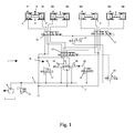
- Figure 1 shows a designated 1 switching system of a gearbox with four actuators A1, A2, A3, A4, which are each formed as a double-sided controllable switching cylinder.
- a switching cylinder A1, A2, A3, A4 each have a first chamber 2 and a second chamber 3, which can be connected via the switching system 1 with a pressure line 4 depending on the position of the individual components of the switching system.
- a motor-driven pump 5 and a pressure regulator 6 provide for a regulated pressure in the pressure line 4.
- a double piston 8 shifts to the left in the illustration of FIG. With the help of a mounted on the double piston 8 shift fork 9 (in Figure 1 only indicated), a reverse gear R is inserted. If the double piston 8 in the illustration of Figure 1, however, moves to the right, the first forward gear G1 of the gearbox is engaged. The position of the double piston 8 shown in FIG. 1 corresponds to a neutral position of the shift fork 9.
- the reverse gear R and the first gear G1 can be inserted, can be on the other actuators A2 to A4, the other gears G2 to G6 switch.
- the assignment of actuator and gear is the figure 1 removable.
- the switching system 1 comprises a switching valve device 10 for selecting an actuator, a group selection valve 11 and two chamber selection valves 12 and 13. With the aid of the group selection valve 11, either the group with the actuators A1 and A2 or the group with the actuators A3 and A4 are selected. Due to the series connection of the valve devices 10, 11 and 12 or 13, a specific chamber of an actuator can be selected so that a pressure medium with a modeled pressure can be conducted from the pressure line 4 into this chamber.
- the switching valve device 10 comprises a first switching valve 14 and a second switching valve 15. Between the valves 14, 15, a spring 16 is arranged, which is supported at one end to the first switching valve 14 and at another end to the second switching valve 15. The spring 16 presses the two switching valves in a respective first position, as shown in Figure 1. In the position of the switching valve device 10 shown in FIG. 1 (both switching valves 14, 15 are in their first position), the chambers 2, 3 of all actuators and the group selection valve 11 and the chamber selection valves 12, 13 are depressurized.
- the first switching valve 14 an electromagnetically actuated signal element 17 is arranged.
- the signal element 17 via the signal line 18 provides a signal pressure, through which the first switching valve 14 can be switched from the first position shown here to a second position.
- the first switching valve 14 connects the pressure line 4 to the group selector valve 11, whereby the second chamber 3 of the actuator A3 would be pressurized at the positions of the valves 11 and 13 shown here.
- the second switching valve 15 is associated with an electromagnetically operable signal element 19, which is connected via a signal line 20 to the second switching valve 15.
- the signal element 19 opens and directs pressure from the pressure line 4 to the switching valve 15, which switches from a first position (first position in Figure 1) to a second position, the possibility of this switching from the position of the first switching valve 14th depends.
- the chamber selection valves 12, 13 and the group selection valve 11 are each assigned a signal element for generating a signal pressure.
- the chamber selection valve 12 is a signal element 21 and the group selector valve 11, a signal element 22 upstream.
- the signal elements 17, 19, 21 and 22 are each formed as electro-magnetically actuated 3/2-way valves.
- the signal pressure in the signal line 18 generates a first switching force, which should be twice as large in the embodiment shown as a second switching force, which results from the signal pressure from the signal line 20.
- the ratio of the switching forces to each other can be adjusted over different areas of the switching valves 14, 15, act on the signal pressures respectively.
- the switching system 1 with the actuators A1 to A4 depressurized. This minimizes leakage losses.
- the first switching valve 14 is pressed in its second position, at the same time the spring 16 is compressed. Due to the series connection of the first switching valve 14 and spring 16, the spring 16 is compressed with the first switching force, apart from frictional forces acting on the first switching valve 14. Thus, the spring 16 presses with this first switching force against the second switching valve 15 and holds it in its first position. Since the second switching force is half the size of the first switching force transmitted by the spring, the second switching valve remains in its first position, even if the associated signal element 19 opens. Only when the signal element 17 closes and the control pressure in the Signal line 18 and thus the first switching force are reduced accordingly, the second switching valve 15 can be pushed by the second switching force in its second position.
- the first switching valve is pushed into its second position, regardless of whether the movement precludes the second switching force, since the first switching force is greater than the second switching force.
- a simultaneous excitation of the two signal elements 17, 18 thus always leads to a unique position of the switching valve arrangement. Due to the given priority to the first switching valve 14 can be in the case of a simultaneous excitation of the two signal elements 17, 18, depending on the position of the group selector valve 11 actuate either the actuator A1 or the actuator A3. The ability to actuate the actuator A1, the reverse gear R and the first forward gear can be engaged. Thus, a vehicle equipped with the switching system 1 motor vehicle could still move.
- the second switching valve 15 can be toggled without restrictions, whereby either the switching system 1 can be depressurized or one of the actuators A2 and A4 can be selected for pressurization.
Abstract
Description
- Die Erfindung betrifft eine Schaltventilvorrichtung für ein Schaltsystem eines Schaltgetriebes, insbesondere für ein Schaltsystem eines Doppelkupplungsgetriebes, das einen ersten Aktuator und wenigstens einen zweiten Aktuator zum Ein- oder Auslegen von Gängen aufweist.
- Aus der
DE 101 34 115 ist eine hydraulische Steuerungsvorrichtung zur Steuerung eines Doppelkupplungsgetriebes mit mehreren Gängen bekannt, das mehrere Aktuatoren zum Einlegen und Auslegen der Gänge aufweist. Das hydraulische Steuerungsvorrichtung lässt sich dort in einen ersten und in einen zweiten Teilkreis aufteilen - Zwischen dem ersten Teilkreis und einer Druckleitung ist ein erstes Schaltventil vorgesehen, das in einer ersten Stellung den ersten Teilkreis von der Druckleitung trennt und in einer zweiten Stellung mit der Druckleitung verbindet. Durch Beaufschlagung des ersten Schaltventils mit einer ersten Schaltkraft mittels einer Ventilansteuerung wird das erste Schaltventil gegen die Kraft einer Feder von der ersten Stellung in die zweite Stellung gebracht. Somit lässt sich ein erster Aktuator innerhalb des ersten Teilkreises über das erste Schaltventil mit der Druckleitung verbinden. Wird die Schaltkraft reduziert oder auf null gesetzt, drückt die Feder das Schaltventil wieder in dessen erste Stellung.
- Des weiteren ist zwischen dem zweiten Teilkreis und der Druckleitung ein zweites Schaltventil vorgesehen, das, ähnlich wie das erste Schaltventil, in einer ersten Stellung den zweiten Teilkreis drucklos stellt und in einer zweiten Stellung den zweiten Teilkreis mit der Druckleitung verbindet. Auch hier stellt eine Ventilansteuerung eine Schaltkraft, eine zweite Schaltkraft, zur Verfügung, um das Schaltventil gegen die Kraft einer Feder in die zweite Stellung zu bringen. Ein zweiter Aktuator des Doppelkupplungsgetriebes, der hier dem zweiten Teilgetriebe zugeordnet sein soll, kann somit mit der Druckleitung verbunden werden.
- Durch das erste und das zweite Schaltventil können folglich die beiden Teilkreise druckfrei gestellt beziehungsweise unter Druck gesetzt werden. Die beiden Schaltventile werden von voneinander unabhängigen Ventilansteuerungen geschaltet. Diese unabhängige Ansteuerung kann dazu führen, dass bei Ausfall einer Ventilansteuerung eines Schaltventils beide Aktuatoren gleichzeitig unter Druck gesetzt werden. Diese wäre beispielsweise bei den Schaltventilen der
DE 101 34 115 , die als elektrisch angesteuerte Magnetschaltventile ausgebildet sind, dann der Fall, wenn fehlerbedingt eines der beiden Schaltventile dauerhaft angeregt wird und das andere Schaltventil wie vorgesehen schaltet. Eine fehlerbedingte gleichzeitige Druckbeaufschlagung von Aktuatoren eines Schaltungssystem kann, unabhängig von der konkreten Aufteilung der hydraulischen Steuerungsvorrichtung gemäß derDE 101 34 115 , bei Doppelkupplungsgetrieben jedoch zu schwerwiegenden Schäden führen. Wenn beispielsweise der erste Aktuator und der zweite Aktuator einem Teilgetriebe eines Doppelkupplungsgetriebes zugeordnet sind, und wenn diese beiden Aktuatoren gleichzeitig mit Druck beaufschlagt werden, würden in diesem Teilgetriebe möglicherweise zwei Gänge gleichzeitig eingelegt. - Zwar ließe sich vor den Aktuatoren anstatt der zwei Schaltventile ein Umschaltventil schalten, das in einer ersten Stellung den ersten Aktuator mit der Druckleitung und in zweiten Stellung den zweiten Aktuator mit der Druckleitung verbindet. Damit wird ausgeschlossen, dass beide Aktuatoren gleichzeitig mit Druckbeaufschlagt werden. Andererseits würde bei Verwendung dieses Umschaltventils immer ein Aktuator unter Druck stehen, was mit gewissen Leckagenverlusten verbunden wäre. Zwar könnte dem Umschaltventil wiederum ein Schaltventil vorgeschaltet sein, das, wie oben bereits beschrieben, die nachgeschalteten Aktuatoren bei Bedarf von der Druckleitung trennt. Fällt jedoch dieses Schaltventil aus, beispielsweise wenn es sich nicht mehr in die Stellung bringen lässt, in der es die Druckleitung mit den Aktuatoren verbindet, können mit den nachgeschalteten Aktuatoren keine Gänge mehr durchgeführt werden. Dies würde möglicherweise bei einem Doppelkupplungsgetriebe in einem Kraftfahrzeug bedeuten, dass Anfahrgänge nicht mehr eingelegt werden können.
- Der Erfindung liegt daher die Aufgabe zugrunde, eine ein erstes und eine zweites Schaltventil umfassende Schaltventilvorrichtung für ein Schaltsystem eines Schaltgetriebes bereitzustellen, das bei Auftreten eines Einzelfehlers zumindest einen sicheren Notbetrieb des Schaltgetriebes ermöglicht.
- Die Aufgabe wird dadurch gelöst, dass zwischen dem ersten und dem zweiten Schaltventil eine Koppelung vorgesehen ist, die die erste Schaltkraft auf das zweite Schaltventil wenigstens zum Teil überträgt, wobei die aus der ersten und der zweiten Schaltkraft resultierende, auf das zweite Schaltventil wirkende Kraft nicht ausreicht, das zweite Schaltventil in dessen zweiten Stellung zu halten oder in dessen zweite Stellung zu drücken.
- Wenn bei der erfindungsgemäßen Steuerungsvorrichtung das erste Schaltventil mit der ersten Schaltkraft beaufschlagt wird, schaltet das erste Schaltventil in dessen zweite Stellung und stellt den ersten Aktuator unter Druck. Gleichzeitig wirkt durch die Koppelung zwischen dem ersten und zweiten Schaltventil diese erste Schaltkraft auch auf das zweite Schaltventil. Da die aus erster und zweiter Schaltkraft resultierende Kraft nicht mehr ausreicht, das zweite Schaltventil aus dessen erste Stellung heraus zu schalten, stellt das erste Schaltventil eine wirksame Sperre für das zweite Schaltventil da. Die Sperre verhindert, dass der erste und zweite Aktuator gleichzeitig unter Druck gesetzt werden, auch wenn beide Schaltventile - durch einen Steuerungsfehler - gleichzeitig mit der jeweiligen Schaltkraft beaufschlagt werden.
- Das zweite Schaltventil wird zudem aus der zweiten Stellung gedrückt, sobald das erste Schaltventil mit der erste Schaltkraft angesteuert wird. Somit wirkt das erste Schaltventil nicht nur als Sperre, sondern drängt das zweite Schaltventil aus dessen zweiten Stellung heraus, auch wenn die zweite Schaltkraft anliegt. Daraus ergibt sich eine klare Priorisierung: Wenn beide Schaltventile fehlerbedingt gleichzeitig angesteuert werden beziehungsweise die jeweiligen Schaltkräfte anliegen, befindet sich das erste Schaltventil in dessen zweiten Stellung lässt eine Verbindung zwischen dem ersten Aktuator und der Druckleitung zu. Bei einem Doppelkupplungsgetriebe für ein Kraftfahrzeug kann dieser erste Aktuator vorzugsweise zum Einlegen wenigstens eines Anfahrganges dienen. Tritt der Fehler eines gleichzeitigen Anliegens von erster und zweiter Schaltkraft auf, kann das Kraftfahrzeug noch bewegt werden.
- Vorzugsweise sind die jeweiligen zweiten Stellungen des ersten und zweiten Schaltventils federbelastet. Zum Schalten von der ersten in die zweite Stellung muss eine Kraft einer Feder überwunden werden. Die Feder drückt zudem das betreffende Schaltventil wieder in die erste Stellung des Schaltventils zurück, wenn nicht die entsprechende Schaltkraft des Schaltventils dies verhindert. Bei der erfindungsgemäßen Steuerungsvorrichtung wirkt somit auf das zweite Schaltventil eine Feder sowie die erste und zweite Schaltkraft.
- Um das zweite Schaltventil aus dessen zweiten Stellung zu drücken, muss die Summe aus erster Schaltkraft und Federkraft größer sein als die zweite Schaltkraft, wobei die erste Schaltkraft und die Federkraft in gleicher Richtung wirken und der zweiten Schaltkraft entgegen gesetzt sind.
- In einem bevorzugten Ausführungsbeispiel ist die auf das zweite Schaltventil wirkende erste Schaltkraft größer als die zweite Schaltkraft. Unabhängig von einer Feder wird dabei das zweite Schaltventil immer in dessen erste Stellung gedrückt oder in dieser Stellung gehalten, sobald die erste Schaltkraft anliegt und von der Koppelung übertragen wird. Vorzugsweise ist die erste Schaltkraft in etwa doppelt so groß wie die zweite Schaltkraft, so dass das zweite Schaltventil sicher in dessen erste Stellung gedrückt wird, auch wenn die zweite Schaltkraft geschaltet ist.
- Der Koppelung zwischen dem ersten und zweiten Schaltventil kann mechanisch sein, aber auch beispielsweise hydraulisch sein.
- Die Koppelung umfasst vorzugsweise eine Feder, wobei die Feder in einer Ruhestellung die Schaltventile in deren jeweiligen ersten Stellungen drückt. Die Feder soll sich in ihrer Ruhestellung befinden, wenn sowohl die erste als auch die zweite Schaltkraft nicht anliegen. Die Feder kann zwischen dem ersten und dem zweiten Schaltventil angeordnet sein, wobei sie zusammengedrückt wird, wenn die eine und/oder die andere Schaltkraft auf die Schaltventile wirken. Die Feder überträgt dabei die erste Schaltkraft des ersten Schaltventils auf das zweite Schaltventil. Entsprechend wird auch die zweite Schaltkraft auf das erste Schaltventil übertragen.
- In einem bevorzugten Ausführungsbeispiel schließt die Koppelung zwischen dem ersten und dem zweiten Schaltventil eine gleichzeitige jeweils zweite Stellung der beiden Schaltventile durch Formschluss aus. Dies kann beispielsweise in dem Ausführungsbeispiel, in dem eine Feder als Koppelung zwischen den Schaltventilen angeordnet ist, dadurch erfolgen, dass die Feder auf Blocklänge zusammengedrückt wird, wenn sich eines der beiden Schaltventile in dessen zweiten Stellung befindet. Dies erhöht zusätzlich die Sicherheit, dass der erste und zweite Aktuator nicht gleichzeitig unter Druck gesetzt werden.
- Dem ersten und/oder zweiten Schaltventil kann jeweils ein Signalelement zur Erzeugung eines Signaldrucks zum Aufbau der jeweiligen Schaltkraft zugeordnet sein, wobei das Signalelement vorzugsweise elektro-mechanisch betätigt werden kann. Durch Anlegen eines Stroms an das Signalelement stellt dieses ein Signaldruck zur Verfügung, durch den das entsprechende Schaltventil hydraulisch betätigt wird. Es ist aber auch möglich, dass das erste und das zweite Schaltventil direkt elektrisch anzusteuern.
- In einem bevorzugten Ausführungsbeispiel entspricht der Signaldruck des Signalelements des ersten Schaltventils dem Signaldruck des Signalelements des zweiten Schaltventils. Dadurch können baugleiche Signalelemente an jeweils eine gleiche Druckleitung angeschlossen werden, was den Aufbau des Schaltsystems vereinfacht.
- Die wirksame Fläche eines mit dem Signaldruck beaufschlagten Kolbens des ersten Schaltventils kann größer sein als eine wirksame Fläche eines mit dem Signaldruck beaufschlagten Kolbens des zweiten Schaltventils. Durch entsprechende Auslegung der Flächen lässt sich ein gewünschtes Verhältnis zwischen der ersten und zweiten Schaltkraft einstellen. Zweckmäßig ist die wirksame Fläche des Kolbens des ersten Schaltventils doppelt so groß wie die entsprechende Fläche des zweiten Schaltventils. Daraus folgt bei jeweils gleichen Signaldrücken ein Verhältnis zwischen erster Schaltkraft und zweiter Schaltkraft von 2:1.
- Das erste oder das zweite Schaltventil kann als 3/2-Wege-Ventil ausgebildet sein. Das 3/2-Schaltventil weist dabei zwei Eingänge und eine Ausgang auf. Ein Eingang verbindet das Schaltventil mit der Druckleitung, während der andere Eingang das Schaltventil mit einem Ölsumpf oder dergleichen verbindet. Der Ausgang verbindet das Schaltventil direkt oder indirekt über weitere Ventile mit dem zugehörigen Aktuator.
- Anhand des in den Figur 1 dargestellten Ausführungsbeispiels wird die Erfindung näher erläutert.
- Figur 1 zeigt ein mit 1 bezeichnetes Schaltsystem eines Schaltgetriebes mit vier Aktuatoren A1, A2, A3, A4, die jeweils als doppelseitig ansteuerbare Schaltzylinder ausgebildet sind. Ein Schaltzylinder A1, A2, A3, A4 weist jeweils eine erste Kammer 2 und eine zweite Kammer 3 auf, die über das Schaltsystem 1 mit einer Druckleitung 4 je nach Stellung der einzelnen Bauteile des Schaltsystems verbunden werden können. Eine motorgetriebene Pumpe 5 und ein Druckregler 6 sorgen für einen geregelten Druck in der Druckleitung 4. Desweiteren verbindet, bei entsprechender Stellung der einzelnen Bauteile, das Schaltsystem 1 die Kammern 2, 3 der Aktuatoren A1 bis A4 mit einer Ölsumpfleitung 7, um sie drucklos stellen zu können.
- Wird beispielsweise die zweite Kammer 3 des Aktuators A1 mit dem regelbaren Druck in der Druckleitung 4 beaufschlagt und gleichzeitig die erste Kammer 2 des Aktuators drucklos gestellt, verschiebt sich ein Doppelkolben 8 in der Darstellung der Figur 1 nach links. Mit Hilfe einer an dem Doppelkolben 8 befestigten Schaltgabel 9 (in Figur 1 nur angedeutet) wird ein Rückwärtsgang R eingelegt. Wird der Doppelkolben 8 in der Darstellung der Figur 1 hingegen nach rechts bewegt, wird der erste Vorwärtsgang G1 des Schaltgetriebes eingelegt. Die in der Figur 1 dargestellte Stellung des Doppelkolbens 8 entspricht einer Neutralstellung der Schaltgabel 9.
- Wie durch Aktuator A1 der Rückwärtsgang R und der erste Gang G1 eingelegt werden kann, lassen sich über die anderen Aktuatoren A2 bis A4 die anderen Gänge G2 bis G6 schalten. Die Zuordnung von Aktuator und Gang ist der Figur 1 entnehmbar.
- Das Schaltsystem 1 umfasst eine Schaltventilvorrichtung 10 zur Auswahl eines Aktuators, ein Gruppenauswahlventil 11 und zwei Kammerauswahlventile 12 und 13. Mit Hilfe des Gruppenauswahlventils 11 wird entweder die Gruppe mit den Aktuatoren A1 und A2 oder die Gruppe mit den Aktuatoren A3 und A4 ausgewählt. Aufgrund der Reihenschaltung der Ventilvorrichtungen 10, 11 und 12 beziehungsweise 13 lässt sich eine bestimmte Kammer eines Aktuators auswählen, so dass in diese Kammer ein Druckmedium mit einem modellierten Druck von der Druckleitung 4 geleitet werden kann.
- Die Schaltventilvorrichtung 10 umfasst ein erstes Schaltventil 14 und ein zweites Schaltventil 15. Zwischen den Ventilen 14, 15 ist eine Feder 16 angeordnet, die sich mit einem Ende an dem ersten Schaltventil 14 und an einem anderen Ende an dem zweiten Schaltventil 15 abstützt. Die Feder 16 drückt die beiden Schaltventile in eine jeweilige erste Stellung, so wie es in Figur 1 dargestellt ist. In der in Figur 1 dargestellten Stellung der Schaltventilvorrichtung 10 (beide Schaltventile 14, 15 befinden sich jeweils in deren ersten Stellung) sind die Kammern 2, 3 aller Aktuatoren sowie das Gruppenauswahlventil 11 und die Kammerauswahlventile 12, 13 drucklos geschaltet.
- Dem ersten Schaltventil 14 ist ein elektro-magnetisch betätigbares Signalelement 17 angeordnet. Im angeregten Zustand (in Figur 1 dargestellt ist der nicht angeregte Zustand) stellt das Signalelement 17 über die Signalleitung 18 ein Signaldruck bereit, durch den sich das erste Schaltventil 14 von der hier dargestellten ersten Stellung in eine zweite Stellung schalten lässt. In dieser zweiten Stellung verbindet das erste Schaltventil 14 die Druckleitung 4 mit dem Gruppenauswahlventil 11, wodurch die zweite Kammer 3 des Aktuators A3 bei den hier darstellten Stellungen der Ventile 11 und 13 unter Druck gesetzt würde.
- Wie auch dem ersten Schaltventil 14 ist dem zweiten Schaltventil 15 ein elektro-magnetisch betätigbares Signalelement 19 zugeordnet, das über eine Signalleitung 20 mit dem zweiten Schaltventil 15 verbunden ist. Im angeregten Zustand öffnet das Signalelement 19 und leitet Druck aus der Druckleitung 4 auf das Schaltventil 15, das von einer ersten Stellung (erste Stellung in Figur 1 dargestellt) in eine zweite Stellung schaltet, wobei die Möglichkeit dieses Schaltens von der Stellung des ersten Schaltventils 14 abhängt.
- In ähnlicher Weise sind auch den Kammerauswahlventilen 12, 13 und dem Gruppenauswahlventil 11 jeweils ein Signalelement zur Erzeugung eines Signaldrucks zugeordnet. Dem Kammerauswahlventil 12 ist ein Signalelement 21 und dem Gruppenauswahlventil 11 ein Signalelement 22 vorgeschaltet. Die Signalelemente 17, 19, 21 und 22 sind jeweils als elektro-magnetisch betätigbare 3/2-Schaltventile ausgebildet.
- Der Signaldruck in der Signalleitung 18 erzeugt eine erste Schaltkraft, die in dem gezeigten Ausführungsbeispiel doppelt so groß sein soll wie eine zweite Schaltkraft, die von dem Signaldruck aus der Signalleitung 20 herrührt. Das Verhältnis der Schaltkräfte zueinander lässt sich dabei über unterschiedlich große Flächen der Schaltventile 14, 15 einstellen, auf die Signaldrücke jeweils wirken.
- In der jeweils ersten Stellung der beiden Schaltventile 14, 15 wird, wie oben bereits erwähnt, das Schaltsystem 1 mit den Aktuatoren A1 bis A4 drucklos gestellt. Dadurch lassen sich Leckageverluste minimieren. Wird nun das Signalelement 17 angesteuert, wird das erste Schaltventil 14 in dessen zweite Stellung gedrückt, wobei gleichzeitig die Feder 16 zusammengedrückt wird. Aufgrund der Reihenschaltung von erstem Schaltventil 14 und Feder 16 wird die Feder 16 mit der ersten Schaltkraft zusammengedrückt, wenn man von Reibkräften absieht, die auf das erste Schaltventil 14 wirken. Somit drückt die Feder 16 mit dieser ersten Schaltkraft gegen das zweite Schaltventil 15 und hält es in dessen ersten Stellung. Da die zweite Schaltkraft halb so groß ist wie die von der Feder übertragene erste Schaltkraft, verbleibt das zweite Schaltventil in dessen ersten Stellung, auch wenn das zugehörige Signalelement 19 öffnet. Erst wenn das Signalelement 17 schließt und der Steuerdruck in der Signalleitung 18 und damit die erste Schaltkraft entsprechend abgebaut werden, kann das zweite Schaltventil 15 durch die zweite Schaltkraft in dessen zweite Stellung geschoben werden.
- Befindet sich hingegen das zweite Schaltventil in dessen zweiten Stellung und wird nun das erste Schaltventil mit der ersten Schaltkraft beaufschlagt, wird das erste Schaltventil in dessen zweite Stellung geschoben, unabhängig davon, ob der Bewegung die zweite Schaltkraft entgegensteht, da die erste Schaltkraft größer ist als die zweite Schaltkraft.
- Eine gleichzeitige Anregung der beiden Signalelemente 17, 18 führt somit immer zu einer eindeutigen Stellung der Schaltventilanordnung. Aufgrund der gegebenen Priorität auf das erste Schaltventil 14 lässt sich im Fall einer gleichzeitigen Anregung der beiden Signalelemente 17, 18 je nach Stellung des Gruppenauswahlventils 11 entweder der Aktuator A1 oder der Aktuator A3 betätigen. Durch die Möglichkeit, den Aktuator A1 zu betätigen, lässt sich der Rückwärtsgang R und der erste Vorwärtsgang einlegen. Somit ließe sich ein mit dem Schaltsystem 1 ausgestattetes Kraftfahrzeug noch fortbewegen.
- Aber auch wenn eines der Signalelemente 17, 19 sich nicht mehr öffnen lässt, ist ein (Not-)Betrieb des Kraftfahrzeugs möglich. Kann beispielsweise kein Signaldruck in der Signalleitung 18 aufgebaut werden, lässt sich das zweite Schaltventil 15 ohne Einschränkungen hin- und herschalten, wodurch wahlweise das Schaltsystem 1 drucklos gestellt oder einer der Aktuatoren A2 und A4 zur Druckbeaufschlagung ausgewählt werden kann.
-
- 1
- Schaltsystem
- 2
- Erste Kammer
- 3
- Zweite Kammer
- 4
- Druckleitung
- 5
- Pumpe
- 6
- Druckregler
- 7
- Ölsumpfleitung
- 8
- Doppelkolben
- 9
- Schaltgabel
- 10
- Schaltventilvorrichtung
- 11
- Gruppenauswahlventil
- 12
- Kammerauswahlventil
- 13
- Kammerauswahlventil
- 14
- Erstes Schaltventil
- 15
- Zweites Schaltventil
- 16
- Feder
- 17
- Signalelement
- 18
- Signalleitung
- 19
- Signalelement
- 20
- Signalleitung
- 21
- Signalelement
- 22
- Signalelement
- A1 bis A4
- Aktuator
- G1 bis G6
- Vorwärtsgang
- R
- Rückwärtsgang
Claims (11)
- Schaltventilvorrichtung (10) für ein Schaltsystem (1) eines Schaltgetriebes, das einen ersten Aktuator und wenigstens einen zweiten Aktuator zum Ein- und Auslegen von Gängen aufweist, mit einem ersten ansteuerbaren Schaltventil (14), durch das in einer ersten Stellung der erste Aktuator drucklos gestellt und in einer zweiten Stellung unter Druck gesetzt werden kann, wobei zum Schalten von der ersten in die zweite Stellung und zum Halten in der zweiten Stellung eine erste Schaltkraft bereitsteht, und mit einem zweiten ansteuerbaren Schaltventil (15), durch das in einer ersten Stellung der zweite Aktuator drucklos gestellt und in einer zweiten Stellung unter Druck gesetzt werden kann, wobei zum Schalten von der ersten in die zweite Stellung und zum Halten in der zweiten Stellung eine zweite Schaltkraft bereitsteht, dadurch gekennzeichnet, dass eine Koppelung (16) zwischen dem ersten Schaltventil (14) und dem zweiten Schaltventil (15) vorgesehen ist, die die erste Schaltkraft auf das zweite Schaltventil (15) wenigstens zum Teil überträgt, wobei die aus der ersten Schaltkraft und aus der zweiten Schaltkraft resultierende, auf das zweite Schaltventil (15) wirkende Kraft nicht ausreicht, das zweite Schaltventil (15) in dessen zweiten Stellung zu halten oder in dessen zweite Stellung zu drücken.
- Schaltventilvorrichtung (10) nach Anspruch 1, dadurch gekennzeichnet, dass die jeweilige zweite Stellung des ersten und zweiten Schaltventils (14, 15) federbelastet ist.
- Schaltventilvorrichtung (10) nach Anspruch 1 oder 2, dadurch gekennzeichnet, dass die erste Schaltkraft größer ist als die zweite Schaltkraft, vorzugsweise etwa doppelt so groß.
- Schaltventilvorrichtung (10) nach einem der Ansprüche 1 bis 3, dadurch gekennzeichnet, dass die Koppelung (16) mechanisch ist.
- Schaltventilvorrichtung (10) nach einem der Ansprüche 1 bis 4, dadurch gekennzeichnet, dass die Koppelung eine Feder (16) umfasst, wobei die Feder (16) in einer Ruhestellung die Schaltventile (14, 15) in deren jeweilige erste Stellung drückt.
- Schaltventilvorrichtung (10) nach einem der Ansprüche 1 bis 5, dadurch gekennzeichnet, dass die Koppelung (16) zwischen dem ersten und zweiten Schaltventil (14, 15) eine gleichzeitige jeweils zweite Stellung der beiden Schaltventile durch Formschluss ausschließt.
- Schaltventilvorrichtung (10) nach einem der Ansprüche 1 bis 6, dadurch gekennzeichnet, dass den Schaltventilen (14, 15) jeweils ein Signalelement (18, 20) zur Erzeugung eines Signaldrucks zum Aufbau einer Schaltkraft zugeordnet sind.
- Schaltventilvorrichtung (10) nach Anspruch 7, dadurch gekennzeichnet, dass der Signaldruck des Signalelements (18) des ersten Schaltventils (14) dem Signaldruck des Signalelements (20) des zweiten Schaltventils (15) entspricht.
- Schaltventilvorrichtung (10) nach Anspruch 7 oder 8, dadurch gekennzeichnet, dass eine wirksame Fläche eines mit dem Signaldruck beaufschlagten Kolbens des ersten Schaltventils (14) größer ist als eine wirksame Fläche eines mit dem Signaldruck beaufschlagten Kolbens des zweiten Schaltventils (15).
- Schaltventilvorrichtung (10) nach Anspruch 9, dadurch gekennzeichnet, dass die wirksame Fläche des Kolbens des ersten Schaltventils (14) in etwa doppelt so groß ist wie die wirksame Fläche des Kolbens des zweiten Schaltventils (15).
- Schaltventilvorrichtung (10) nach einem der Ansprüche 1 bis 10, dadurch gekennzeichnet, dass wenigstens eines der Schaltventile (14, 15) als 3/2-Schaltventil ausgebildet ist.
Priority Applications (4)
| Application Number | Priority Date | Filing Date | Title |
|---|---|---|---|
| EP05102756A EP1710477B1 (de) | 2005-04-07 | 2005-04-07 | Schaltventilvorrichtung für ein Schaltsystem eines Schaltgetriebes |
| DE502005006690T DE502005006690D1 (de) | 2005-04-07 | 2005-04-07 | Schaltventilvorrichtung für ein Schaltsystem eines Schaltgetriebes |
| US11/398,194 US7410438B2 (en) | 2005-04-07 | 2006-04-05 | Switching-valve arrangement for a shifting system of an automatic transmission |
| CN2006100741752A CN1844717B (zh) | 2005-04-07 | 2006-04-07 | 用于换档变速器的换档系统的转换阀装置 |
Applications Claiming Priority (1)
| Application Number | Priority Date | Filing Date | Title |
|---|---|---|---|
| EP05102756A EP1710477B1 (de) | 2005-04-07 | 2005-04-07 | Schaltventilvorrichtung für ein Schaltsystem eines Schaltgetriebes |
Publications (2)
| Publication Number | Publication Date |
|---|---|
| EP1710477A1 true EP1710477A1 (de) | 2006-10-11 |
| EP1710477B1 EP1710477B1 (de) | 2009-02-25 |
Family
ID=34939181
Family Applications (1)
| Application Number | Title | Priority Date | Filing Date |
|---|---|---|---|
| EP05102756A Expired - Fee Related EP1710477B1 (de) | 2005-04-07 | 2005-04-07 | Schaltventilvorrichtung für ein Schaltsystem eines Schaltgetriebes |
Country Status (4)
| Country | Link |
|---|---|
| US (1) | US7410438B2 (de) |
| EP (1) | EP1710477B1 (de) |
| CN (1) | CN1844717B (de) |
| DE (1) | DE502005006690D1 (de) |
Cited By (8)
| Publication number | Priority date | Publication date | Assignee | Title |
|---|---|---|---|---|
| DE102006016397A1 (de) * | 2006-04-07 | 2007-10-11 | Hofer Mechatronic Gmbh | Getriebe für ein Kraftfahrzeug |
| EP2072867A1 (de) * | 2007-12-18 | 2009-06-24 | C.R.F. Società Consortile per Azioni | Elektrohydraulisches Steuergerät für ein Kraftfahrzeuggetriebe mit mindestens fünf Vorwärtsgängen und einem Rückwärtsgang |
| EP2072866A1 (de) * | 2007-12-18 | 2009-06-24 | C.R.F. Società Consortile per Azioni | Elektrohydraulische Steuervorrichtung für ein Kraftfahrzeuggetriebe mit mindestens fünf Vorwärtsgängen und einem Rückwärtsgang |
| GB2503282A (en) * | 2012-06-22 | 2013-12-25 | Drive System Design Ltd | Floating gear for transmission having friction and dog clutches on opposing sides |
| DE202013101840U1 (de) * | 2013-04-26 | 2014-07-29 | Hofer Mechatronik Gmbh | Hydraulische Schaltung eines Doppelkupplungsgetriebes |
| WO2016096092A1 (de) * | 2014-12-18 | 2016-06-23 | Daimler Ag | Hydrauliksystem für ein kraftfahrzeuggetriebe |
| DE102006062902B4 (de) * | 2006-04-07 | 2016-11-17 | Hofer Mechatronik Gmbh | Verfahren zum Betrieb eines Getriebes für ein Kraftfahrzeug |
| DE102006063034B3 (de) * | 2006-04-07 | 2018-02-01 | Hofer Mechatronik Gmbh | Verfahren zur Steuerung eines Getriebes für ein Kraftfahrzeug |
Families Citing this family (50)
| Publication number | Priority date | Publication date | Assignee | Title |
|---|---|---|---|---|
| US7011600B2 (en) | 2003-02-28 | 2006-03-14 | Fallbrook Technologies Inc. | Continuously variable transmission |
| MX2007003828A (es) | 2004-10-05 | 2007-04-20 | Fallbrook Technologies Inc | Transmision continuamente variable. |
| KR101831822B1 (ko) | 2005-10-28 | 2018-02-23 | 폴브룩 인텔렉츄얼 프로퍼티 컴퍼니 엘엘씨 | 전동 드라이브 |
| PL1954959T3 (pl) | 2005-11-22 | 2013-10-31 | Fallbrook Ip Co Llc | Przekładnia bezstopniowa |
| KR101317329B1 (ko) | 2005-12-09 | 2013-10-15 | 폴브룩 테크놀로지즈 인크 | 연속 가변 변속기 |
| EP1811202A1 (de) | 2005-12-30 | 2007-07-25 | Fallbrook Technologies, Inc. | Stufenloses Getriebe |
| WO2009006481A2 (en) | 2007-07-05 | 2009-01-08 | Fallbrook Technologies Inc. | Continuously variable transmission |
| DE102006035134A1 (de) * | 2006-07-29 | 2008-01-31 | Zf Friedrichshafen Ag | Kupplungssystem |
| JP4404911B2 (ja) * | 2007-01-09 | 2010-01-27 | ジヤトコ株式会社 | 自動変速機 |
| EP2125469A2 (de) | 2007-02-01 | 2009-12-02 | Fallbrook Technologies Inc. | System und verfahren zur getriebe- und/oder antriebsmotorsteuerung |
| CN101657653B (zh) | 2007-02-12 | 2014-07-16 | 福博科知识产权有限责任公司 | 一种传动装置 |
| TWI461615B (zh) | 2007-02-16 | 2014-11-21 | Fallbrook Ip Co Llc | 無限可變變速器、連續可變變速器、方法、組件、次組件以及其零件 |
| JP4358248B2 (ja) * | 2007-03-14 | 2009-11-04 | ジヤトコ株式会社 | 自動変速機 |
| JP4418477B2 (ja) * | 2007-03-22 | 2010-02-17 | ジヤトコ株式会社 | 自動変速機 |
| EP2573425A3 (de) | 2007-04-24 | 2017-07-26 | Fallbrook Intellectual Property Company LLC | Elektrische Fahrantriebe |
| WO2008154437A1 (en) | 2007-06-11 | 2008-12-18 | Fallbrook Technologies Inc. | Continuously variable transmission |
| CN103939602B (zh) | 2007-11-16 | 2016-12-07 | 福博科知识产权有限责任公司 | 用于变速传动装置的控制器 |
| DE102007057203B4 (de) * | 2007-11-26 | 2020-07-02 | Getrag-Ford Transmissions Gmbh | Verfahren zum Einlegen eines Ganges in eine Gangposition in einem automatisierten Schaltgetriebe |
| CA2708634C (en) | 2007-12-21 | 2017-08-01 | Fallbrook Technologies Inc. | Automatic transmissions and methods therefor |
| WO2009148461A1 (en) | 2008-06-06 | 2009-12-10 | Fallbrook Technologies Inc. | Infinitely variable transmissions, continuously variable transmissions, methods, assemblies, subassemblies, and components therefor |
| CN107246463A (zh) | 2008-06-23 | 2017-10-13 | 福博科知识产权有限责任公司 | 无级变速器 |
| CA2732668C (en) | 2008-08-05 | 2017-11-14 | Fallbrook Technologies Inc. | Methods for control of transmission and prime mover |
| US8469856B2 (en) | 2008-08-26 | 2013-06-25 | Fallbrook Intellectual Property Company Llc | Continuously variable transmission |
| US8167759B2 (en) | 2008-10-14 | 2012-05-01 | Fallbrook Technologies Inc. | Continuously variable transmission |
| US8206265B2 (en) * | 2008-10-21 | 2012-06-26 | GM Global Technology Operations LLC | Control system for dual clutch transmission |
| US8439804B2 (en) * | 2008-10-28 | 2013-05-14 | Allison Transmission, Inc. | Electro-hydraulic control including blocking features for multi-speed automatic transmission |
| GB2468867A (en) * | 2009-03-24 | 2010-09-29 | Gm Global Tech Operations Inc | Device for actuating a dual clutch transmission having flow and pressure regulators |
| PL2419658T3 (pl) | 2009-04-16 | 2014-02-28 | Fallbrook Ip Co Llc | Zespół stojana i mechanizm zmiany biegów do bezstopniowej skrzyni biegów |
| US8475336B2 (en) * | 2009-07-30 | 2013-07-02 | GM Global Technology Operations LLC | Hydraulic control system for a dual clutch transmission |
| GB2473054A (en) * | 2009-08-28 | 2011-03-02 | Gm Global Tech Operations Inc | Synchronizer actuator having a piston that delimits three chambers |
| US8356529B2 (en) * | 2009-09-09 | 2013-01-22 | GM Global Technology Operations LLC | Hydraulic control systems for dual clutch transmissions |
| US8359941B2 (en) * | 2009-09-29 | 2013-01-29 | GM Global Technology Operations LLC | Hydraulic control systems for dual clutch transmissions |
| US8512195B2 (en) | 2010-03-03 | 2013-08-20 | Fallbrook Intellectual Property Company Llc | Infinitely variable transmissions, continuously variable transmissions, methods, assemblies, subassemblies, and components therefor |
| EP2410213A3 (de) | 2010-07-21 | 2012-05-16 | hofer mechatronik GmbH | Getriebehydraulik eines Getriebes mit mehreren Kupplungen und Steuerungsverfahren mit hydraulischen Ventilen für mehrere Kupplungen umfassende Getriebe, die eine erhöhte Betriebssicherheit bieten |
| DE102010036545B4 (de) * | 2010-07-21 | 2015-01-08 | Hofer Mechatronik Gmbh | Getriebehydraulik eines Getriebes mit mehreren Kupplungen und Steuerungsverfahren mit hydraulischen Ventilen für mehrere Kupplungen umfassende Getriebe, die eine erhöhte Betriebssicherheit bieten |
| US8888643B2 (en) | 2010-11-10 | 2014-11-18 | Fallbrook Intellectual Property Company Llc | Continuously variable transmission |
| US8733521B2 (en) * | 2010-12-06 | 2014-05-27 | Gm Global Technology Operations | Apparatus for and method of controlling a dual clutch transmission |
| US8942901B2 (en) * | 2010-12-09 | 2015-01-27 | Gm Global Technology Operations, Llc | Method of controlling a hydraulic control system for a dual clutch transmission |
| WO2013112408A1 (en) | 2012-01-23 | 2013-08-01 | Fallbrook Intellectual Property Company Llc | Infinitely variable transmissions, continuously variable transmissions methods, assemblies, subassemblies, and components therefor |
| JP6660876B2 (ja) | 2013-04-19 | 2020-03-11 | フォールブルック インテレクチュアル プロパティー カンパニー エルエルシー | 連続可変変速機 |
| CN103363101B (zh) * | 2013-07-30 | 2015-11-18 | 长城汽车股份有限公司 | 双离合器自动变速器及其液压换挡控制系统 |
| JP6511756B2 (ja) * | 2014-09-29 | 2019-05-15 | アイシン精機株式会社 | 変速機用の液圧制御回路 |
| US10400872B2 (en) | 2015-03-31 | 2019-09-03 | Fallbrook Intellectual Property Company Llc | Balanced split sun assemblies with integrated differential mechanisms, and variators and drive trains including balanced split sun assemblies |
| CN105020391A (zh) * | 2015-07-27 | 2015-11-04 | 安徽江淮汽车股份有限公司 | 变速箱的挡位液压控制系统 |
| US10047861B2 (en) | 2016-01-15 | 2018-08-14 | Fallbrook Intellectual Property Company Llc | Systems and methods for controlling rollback in continuously variable transmissions |
| JP7137475B2 (ja) | 2016-03-18 | 2022-09-14 | フォールブルック インテレクチュアル プロパティー カンパニー エルエルシー | 連続可変変速機、システムおよび方法 |
| US10023266B2 (en) | 2016-05-11 | 2018-07-17 | Fallbrook Intellectual Property Company Llc | Systems and methods for automatic configuration and automatic calibration of continuously variable transmissions and bicycles having continuously variable transmissions |
| US11215268B2 (en) | 2018-11-06 | 2022-01-04 | Fallbrook Intellectual Property Company Llc | Continuously variable transmissions, synchronous shifting, twin countershafts and methods for control of same |
| US11174922B2 (en) | 2019-02-26 | 2021-11-16 | Fallbrook Intellectual Property Company Llc | Reversible variable drives and systems and methods for control in forward and reverse directions |
| US11885081B2 (en) * | 2021-08-11 | 2024-01-30 | Caterpillar Paving Products Inc. | Milling machine with hydraulically actuated rotor drive transmission |
Citations (8)
| Publication number | Priority date | Publication date | Assignee | Title |
|---|---|---|---|---|
| US3747439A (en) * | 1970-05-09 | 1973-07-24 | Toyota Motor Co Ltd | Hydraulic control system for automatic transmissions |
| US4186627A (en) * | 1977-04-22 | 1980-02-05 | Toyota Jidosha Kogyo Kabushiki Kaisha | Oil pressure control means for an automatic transmission |
| US4198022A (en) * | 1978-03-10 | 1980-04-15 | Johns-Manville Corporation | Power cable guide for high-mast luminaire raising and lowering system |
| US4349088A (en) * | 1978-11-07 | 1982-09-14 | Aisin-Warner Kabushiki Kaisha | Device for controlling a lock-up clutch in an automatic transmission with a lock-up clutch equipped fluid torque converter |
| US4445393A (en) * | 1982-01-18 | 1984-05-01 | Eaton Corporation | Fluid actuated shift bar housing assembly |
| US4462280A (en) * | 1981-02-17 | 1984-07-31 | Nissan Motor Co., Limited | Manual valve for hydraulic control system for automatic transmission |
| EP0294033A2 (de) * | 1987-06-01 | 1988-12-07 | SATURN CORPORATION (a Delaware corp.) | Getriebesteuerschaltung mit einem Kupplungsvorrangsventil |
| DE10134115A1 (de) | 2001-07-13 | 2003-01-23 | Volkswagen Ag | Hydraulikkreis und Verfahren zur hydraulischen Steuerung eines Doppelkupplungsgetriebes |
Family Cites Families (5)
| Publication number | Priority date | Publication date | Assignee | Title |
|---|---|---|---|---|
| JPS52109078A (en) * | 1976-03-09 | 1977-09-12 | Toyota Motor Corp | Speed change controller for fluid-system automatic transmission |
| US5044216A (en) * | 1990-08-30 | 1991-09-03 | Eaton Corporation | Transmission shift control |
| GB2372080B (en) * | 2001-02-12 | 2004-09-29 | Luk Lamellen & Kupplungsbau | Hydraulic actuation systems |
| JP2002372144A (ja) * | 2001-06-15 | 2002-12-26 | Fuji Heavy Ind Ltd | 自動変速機の油圧制御装置 |
| DE502004006421D1 (de) * | 2004-09-02 | 2008-04-17 | Getrag Ford Transmissions Gmbh | Hydraulische Steuerungsvorrichtung für ein automatisiertes Doppelkupplungsgetriebe |
-
2005
- 2005-04-07 DE DE502005006690T patent/DE502005006690D1/de active Active
- 2005-04-07 EP EP05102756A patent/EP1710477B1/de not_active Expired - Fee Related
-
2006
- 2006-04-05 US US11/398,194 patent/US7410438B2/en active Active
- 2006-04-07 CN CN2006100741752A patent/CN1844717B/zh not_active Expired - Fee Related
Patent Citations (9)
| Publication number | Priority date | Publication date | Assignee | Title |
|---|---|---|---|---|
| US3747439A (en) * | 1970-05-09 | 1973-07-24 | Toyota Motor Co Ltd | Hydraulic control system for automatic transmissions |
| US4186627A (en) * | 1977-04-22 | 1980-02-05 | Toyota Jidosha Kogyo Kabushiki Kaisha | Oil pressure control means for an automatic transmission |
| US4198022A (en) * | 1978-03-10 | 1980-04-15 | Johns-Manville Corporation | Power cable guide for high-mast luminaire raising and lowering system |
| US4349088A (en) * | 1978-11-07 | 1982-09-14 | Aisin-Warner Kabushiki Kaisha | Device for controlling a lock-up clutch in an automatic transmission with a lock-up clutch equipped fluid torque converter |
| US4462280A (en) * | 1981-02-17 | 1984-07-31 | Nissan Motor Co., Limited | Manual valve for hydraulic control system for automatic transmission |
| US4445393A (en) * | 1982-01-18 | 1984-05-01 | Eaton Corporation | Fluid actuated shift bar housing assembly |
| EP0294033A2 (de) * | 1987-06-01 | 1988-12-07 | SATURN CORPORATION (a Delaware corp.) | Getriebesteuerschaltung mit einem Kupplungsvorrangsventil |
| EP0294033B1 (de) | 1987-06-01 | 1992-07-08 | SATURN CORPORATION (a Delaware corp.) | Getriebesteuerschaltung mit einem Kupplungsvorrangsventil |
| DE10134115A1 (de) | 2001-07-13 | 2003-01-23 | Volkswagen Ag | Hydraulikkreis und Verfahren zur hydraulischen Steuerung eines Doppelkupplungsgetriebes |
Cited By (14)
| Publication number | Priority date | Publication date | Assignee | Title |
|---|---|---|---|---|
| DE102006016397A1 (de) * | 2006-04-07 | 2007-10-11 | Hofer Mechatronic Gmbh | Getriebe für ein Kraftfahrzeug |
| DE102006063034B3 (de) * | 2006-04-07 | 2018-02-01 | Hofer Mechatronik Gmbh | Verfahren zur Steuerung eines Getriebes für ein Kraftfahrzeug |
| DE102006062902B4 (de) * | 2006-04-07 | 2016-11-17 | Hofer Mechatronik Gmbh | Verfahren zum Betrieb eines Getriebes für ein Kraftfahrzeug |
| DE102006016397B4 (de) * | 2006-04-07 | 2014-08-07 | Hofer Mechatronik Gmbh | Getriebe und ein Verfahren zur Steuerung eines Getriebes für ein Kraftfahrzeug |
| US8752444B2 (en) | 2007-12-18 | 2014-06-17 | C.R.F. Societa Consortile Per Azioni | Electro-hydraulic control apparatus for a motor-vehicle transmission with at least five forward gears and one reverse gear |
| US8447478B2 (en) | 2007-12-18 | 2013-05-21 | C.R.F. Societa Consortile Per Azioni | Electro-hydraulic control apparatus for a motor vehicle transmission with at least five forward gears and one reverse gear |
| US8429993B2 (en) | 2007-12-18 | 2013-04-30 | C.R.F. Societa Consortile Per Azioni | Electro-hydraulic control apparatus for a motor-vehicle transmission with at least five forward gears and one reverse gear |
| EP2072866A1 (de) * | 2007-12-18 | 2009-06-24 | C.R.F. Società Consortile per Azioni | Elektrohydraulische Steuervorrichtung für ein Kraftfahrzeuggetriebe mit mindestens fünf Vorwärtsgängen und einem Rückwärtsgang |
| EP2072867A1 (de) * | 2007-12-18 | 2009-06-24 | C.R.F. Società Consortile per Azioni | Elektrohydraulisches Steuergerät für ein Kraftfahrzeuggetriebe mit mindestens fünf Vorwärtsgängen und einem Rückwärtsgang |
| GB2503282A (en) * | 2012-06-22 | 2013-12-25 | Drive System Design Ltd | Floating gear for transmission having friction and dog clutches on opposing sides |
| DE202013101840U1 (de) * | 2013-04-26 | 2014-07-29 | Hofer Mechatronik Gmbh | Hydraulische Schaltung eines Doppelkupplungsgetriebes |
| DE102014105854A1 (de) | 2013-04-26 | 2014-10-30 | Hofer Mechatronik Gmbh | Hydraulische Schaltung, insbesondere eines Doppelkupplungsgetriebes, sowie Verfahren zur Steuerung eines Kupplungsschnellentleerventils |
| WO2016096092A1 (de) * | 2014-12-18 | 2016-06-23 | Daimler Ag | Hydrauliksystem für ein kraftfahrzeuggetriebe |
| US10612648B2 (en) | 2014-12-18 | 2020-04-07 | Daimler Ag | Hydraulic system for a motor vehicle transmission |
Also Published As
| Publication number | Publication date |
|---|---|
| EP1710477B1 (de) | 2009-02-25 |
| DE502005006690D1 (de) | 2009-04-09 |
| US7410438B2 (en) | 2008-08-12 |
| CN1844717A (zh) | 2006-10-11 |
| CN1844717B (zh) | 2010-05-12 |
| US20060234826A1 (en) | 2006-10-19 |
Similar Documents
| Publication | Publication Date | Title |
|---|---|---|
| EP1710477B1 (de) | Schaltventilvorrichtung für ein Schaltsystem eines Schaltgetriebes | |
| EP1635091B1 (de) | Hydraulische Steuerungsvorrichtung für ein automatisiertes Doppelkupplungsgetriebe | |
| EP1767824B1 (de) | Hydraulische Steuerungsvorrichtung für ein automatisiertes Doppelkupplungsgetriebe | |
| EP1767825B1 (de) | Hydraulische Steuerungsvorrichtung für ein automatisiertes Doppelkupplungsgetriebe | |
| DE10134115B4 (de) | Doppelkupplungsgetriebe eines Kraftfahrzeuges mit einem Hydraulikkreis und Verfahren zur hydraulischen Steuerung eines Doppelkupplungsgetriebes | |
| DE102012200202B4 (de) | Hydraulische Schaltvorrichtung für ein Automatikgetriebe | |
| EP1950463B1 (de) | Hydraulische Steuerungsvorrichtung für ein automatisiertes Doppelkupplungsgetriebe | |
| DE102013003894A1 (de) | Hydrauliksystem für ein Doppelkupplungsgetriebe | |
| DE102009005755A1 (de) | Steuerungseinrichtung für ein automatisiertes Zahnräderwechselgetriebe | |
| EP3058250A2 (de) | Hydraulische steuerungsvorrichtung für ein automatikgetriebe | |
| EP2382403A1 (de) | Steuerungseinrichtung für ein automatisiertes zahnräderwechselgetriebe | |
| EP2019236B1 (de) | Doppelkupplungsgetriebe mit einer Vorrichtung zur Ansteuerung einer Mehrzahl hydraulischer Schaltzylinder | |
| WO2014187553A1 (de) | Verfahren zum betreiben einer getriebeeinrichtung sowie entsprechende getriebeeinrichtung | |
| DE4114713A1 (de) | Hydraulische steuereinrichtung | |
| DE102010001069A1 (de) | Vorrichtung zur Ansteuerung von hydraulischen Schaltzylindern | |
| DE4208060A1 (de) | Elektrohydraulisches getriebesteuerungssystem | |
| DE3836421C2 (de) | Elektrohydraulische Steuereinrichtung für ein automatisches Schaltgetriebe | |
| DE10239915B4 (de) | Vorrichtung zur Ansteuerung eines hydraulisch betätigbaren Schaltelementes | |
| DE2212679B2 (de) | Hydraulische Schaltvorrichtung für Lastschaltgetriebe mit Sicherung gegen Fehlschaltungen | |
| DE102007033690A1 (de) | Hydraulisches System zur Steuerung eines Doppelkupplungsgetriebes | |
| EP1239195B1 (de) | Gangaktuator zum Ein/Auslegen von Gängen eines Getriebes | |
| EP1921351B1 (de) | Hydraulische Steuerungsvorrichtung für ein automatisiertes Doppelkupplungsgetriebe | |
| DE102005057816A1 (de) | Verfahren zum Betätigen von Schaltelementen eines Doppelkupplungsgetriebes | |
| DE102009005752A1 (de) | Steuerungseinrichtung für ein automatisiertes Zahnräderwechselgetriebe eines Kraftfahrzeugs | |
| EP1881239A2 (de) | Hydraulisches System zur Steuerung eines Doppelkupplungsgetriebes |
Legal Events
| Date | Code | Title | Description |
|---|---|---|---|
| PUAI | Public reference made under article 153(3) epc to a published international application that has entered the european phase |
Free format text: ORIGINAL CODE: 0009012 |
|
| AK | Designated contracting states |
Kind code of ref document: A1 Designated state(s): AT BE BG CH CY CZ DE DK EE ES FI FR GB GR HU IE IS IT LI LT LU MC NL PL PT RO SE SI SK TR |
|
| AX | Request for extension of the european patent |
Extension state: AL BA HR LV MK YU |
|
| 17P | Request for examination filed |
Effective date: 20070411 |
|
| AKX | Designation fees paid |
Designated state(s): DE FR GB |
|
| 17Q | First examination report despatched |
Effective date: 20071002 |
|
| GRAP | Despatch of communication of intention to grant a patent |
Free format text: ORIGINAL CODE: EPIDOSNIGR1 |
|
| GRAS | Grant fee paid |
Free format text: ORIGINAL CODE: EPIDOSNIGR3 |
|
| GRAA | (expected) grant |
Free format text: ORIGINAL CODE: 0009210 |
|
| AK | Designated contracting states |
Kind code of ref document: B1 Designated state(s): DE FR GB |
|
| REG | Reference to a national code |
Ref country code: GB Ref legal event code: FG4D Free format text: NOT ENGLISH |
|
| REF | Corresponds to: |
Ref document number: 502005006690 Country of ref document: DE Date of ref document: 20090409 Kind code of ref document: P |
|
| PLBE | No opposition filed within time limit |
Free format text: ORIGINAL CODE: 0009261 |
|
| STAA | Information on the status of an ep patent application or granted ep patent |
Free format text: STATUS: NO OPPOSITION FILED WITHIN TIME LIMIT |
|
| 26N | No opposition filed |
Effective date: 20091126 |
|
| REG | Reference to a national code |
Ref country code: FR Ref legal event code: PLFP Year of fee payment: 12 |
|
| REG | Reference to a national code |
Ref country code: FR Ref legal event code: PLFP Year of fee payment: 13 |
|
| REG | Reference to a national code |
Ref country code: FR Ref legal event code: PLFP Year of fee payment: 14 |
|
| PGFP | Annual fee paid to national office [announced via postgrant information from national office to epo] |
Ref country code: GB Payment date: 20200327 Year of fee payment: 16 |
|
| PGFP | Annual fee paid to national office [announced via postgrant information from national office to epo] |
Ref country code: FR Payment date: 20200320 Year of fee payment: 16 |
|
| PGFP | Annual fee paid to national office [announced via postgrant information from national office to epo] |
Ref country code: DE Payment date: 20200317 Year of fee payment: 16 |
|
| REG | Reference to a national code |
Ref country code: DE Ref legal event code: R119 Ref document number: 502005006690 Country of ref document: DE |
|
| GBPC | Gb: european patent ceased through non-payment of renewal fee |
Effective date: 20210407 |
|
| PG25 | Lapsed in a contracting state [announced via postgrant information from national office to epo] |
Ref country code: FR Free format text: LAPSE BECAUSE OF NON-PAYMENT OF DUE FEES Effective date: 20210430 Ref country code: GB Free format text: LAPSE BECAUSE OF NON-PAYMENT OF DUE FEES Effective date: 20210407 Ref country code: DE Free format text: LAPSE BECAUSE OF NON-PAYMENT OF DUE FEES Effective date: 20211103 |