EP1710326B1 - Surface-coated cutting tool - Google Patents
Surface-coated cutting tool Download PDFInfo
- Publication number
- EP1710326B1 EP1710326B1 EP04819883.2A EP04819883A EP1710326B1 EP 1710326 B1 EP1710326 B1 EP 1710326B1 EP 04819883 A EP04819883 A EP 04819883A EP 1710326 B1 EP1710326 B1 EP 1710326B1
- Authority
- EP
- European Patent Office
- Prior art keywords
- cutting
- cutting tool
- coating film
- film
- sintered body
- Prior art date
- Legal status (The legal status is an assumption and is not a legal conclusion. Google has not performed a legal analysis and makes no representation as to the accuracy of the status listed.)
- Active
Links
- 238000005520 cutting process Methods 0.000 title claims description 126
- 239000011248 coating agent Substances 0.000 claims description 77
- 238000000576 coating method Methods 0.000 claims description 77
- 238000007373 indentation Methods 0.000 claims description 29
- 238000012360 testing method Methods 0.000 claims description 14
- 229910052804 chromium Inorganic materials 0.000 claims description 12
- 238000007733 ion plating Methods 0.000 claims description 10
- 229910052751 metal Inorganic materials 0.000 claims description 10
- 239000002184 metal Substances 0.000 claims description 10
- 150000001875 compounds Chemical class 0.000 claims description 9
- 229910003460 diamond Inorganic materials 0.000 claims description 9
- 239000010432 diamond Substances 0.000 claims description 9
- 150000004767 nitrides Chemical class 0.000 claims description 9
- TWNQGVIAIRXVLR-UHFFFAOYSA-N oxo(oxoalumanyloxy)alumane Chemical compound O=[Al]O[Al]=O TWNQGVIAIRXVLR-UHFFFAOYSA-N 0.000 claims description 8
- 238000005240 physical vapour deposition Methods 0.000 claims description 8
- 229910000997 High-speed steel Inorganic materials 0.000 claims description 7
- 229910052581 Si3N4 Inorganic materials 0.000 claims description 7
- HQVNEWCFYHHQES-UHFFFAOYSA-N silicon nitride Chemical compound N12[Si]34N5[Si]62N3[Si]51N64 HQVNEWCFYHHQES-UHFFFAOYSA-N 0.000 claims description 7
- 238000001755 magnetron sputter deposition Methods 0.000 claims description 6
- MTPVUVINMAGMJL-UHFFFAOYSA-N trimethyl(1,1,2,2,2-pentafluoroethyl)silane Chemical compound C[Si](C)(C)C(F)(F)C(F)(F)F MTPVUVINMAGMJL-UHFFFAOYSA-N 0.000 claims description 6
- 239000011195 cermet Substances 0.000 claims description 5
- 229910052720 vanadium Inorganic materials 0.000 claims description 5
- 239000000919 ceramic Substances 0.000 claims description 4
- 238000003801 milling Methods 0.000 claims description 4
- 229910052582 BN Inorganic materials 0.000 claims description 3
- PZNSFCLAULLKQX-UHFFFAOYSA-N Boron nitride Chemical compound N#B PZNSFCLAULLKQX-UHFFFAOYSA-N 0.000 claims description 3
- OSIVBHBGRFWHOS-UHFFFAOYSA-N dicarboxycarbamic acid Chemical compound OC(=O)N(C(O)=O)C(O)=O OSIVBHBGRFWHOS-UHFFFAOYSA-N 0.000 claims 1
- IJGRMHOSHXDMSA-UHFFFAOYSA-N Atomic nitrogen Chemical compound N#N IJGRMHOSHXDMSA-UHFFFAOYSA-N 0.000 description 78
- 239000010410 layer Substances 0.000 description 58
- 229910052757 nitrogen Inorganic materials 0.000 description 39
- 239000010936 titanium Substances 0.000 description 35
- VNWKTOKETHGBQD-UHFFFAOYSA-N methane Chemical compound C VNWKTOKETHGBQD-UHFFFAOYSA-N 0.000 description 26
- 238000011084 recovery Methods 0.000 description 19
- ATJFFYVFTNAWJD-UHFFFAOYSA-N Tin Chemical compound [Sn] ATJFFYVFTNAWJD-UHFFFAOYSA-N 0.000 description 17
- 238000000034 method Methods 0.000 description 17
- 229910052718 tin Inorganic materials 0.000 description 17
- 239000011230 binding agent Substances 0.000 description 14
- 239000002245 particle Substances 0.000 description 13
- 239000000203 mixture Substances 0.000 description 10
- 239000012535 impurity Substances 0.000 description 9
- 230000015572 biosynthetic process Effects 0.000 description 8
- XEEYBQQBJWHFJM-UHFFFAOYSA-N Iron Chemical group [Fe] XEEYBQQBJWHFJM-UHFFFAOYSA-N 0.000 description 7
- QVGXLLKOCUKJST-UHFFFAOYSA-N atomic oxygen Chemical compound [O] QVGXLLKOCUKJST-UHFFFAOYSA-N 0.000 description 7
- 239000007789 gas Substances 0.000 description 7
- 230000003647 oxidation Effects 0.000 description 7
- 238000007254 oxidation reaction Methods 0.000 description 7
- 229910052760 oxygen Inorganic materials 0.000 description 7
- 239000001301 oxygen Substances 0.000 description 7
- 229910052719 titanium Inorganic materials 0.000 description 7
- XKRFYHLGVUSROY-UHFFFAOYSA-N Argon Chemical compound [Ar] XKRFYHLGVUSROY-UHFFFAOYSA-N 0.000 description 6
- 239000013078 crystal Substances 0.000 description 6
- 239000012071 phase Substances 0.000 description 6
- 230000000694 effects Effects 0.000 description 5
- 230000006872 improvement Effects 0.000 description 5
- 239000000463 material Substances 0.000 description 5
- 229910034327 TiC Inorganic materials 0.000 description 4
- 239000002826 coolant Substances 0.000 description 4
- 238000001816 cooling Methods 0.000 description 4
- 239000011777 magnesium Substances 0.000 description 4
- 230000000737 periodic effect Effects 0.000 description 4
- 239000006104 solid solution Substances 0.000 description 4
- 229910052782 aluminium Inorganic materials 0.000 description 3
- PNEYBMLMFCGWSK-UHFFFAOYSA-N aluminium oxide Inorganic materials [O-2].[O-2].[O-2].[Al+3].[Al+3] PNEYBMLMFCGWSK-UHFFFAOYSA-N 0.000 description 3
- 238000000137 annealing Methods 0.000 description 3
- 229910052786 argon Inorganic materials 0.000 description 3
- 229910052796 boron Inorganic materials 0.000 description 3
- 229910052791 calcium Inorganic materials 0.000 description 3
- 239000011247 coating layer Substances 0.000 description 3
- 238000007542 hardness measurement Methods 0.000 description 3
- 239000000314 lubricant Substances 0.000 description 3
- 229910052749 magnesium Inorganic materials 0.000 description 3
- 150000001247 metal acetylides Chemical class 0.000 description 3
- 238000010791 quenching Methods 0.000 description 3
- 230000000171 quenching effect Effects 0.000 description 3
- 239000012495 reaction gas Substances 0.000 description 3
- 230000035939 shock Effects 0.000 description 3
- 238000005245 sintering Methods 0.000 description 3
- 239000000758 substrate Substances 0.000 description 3
- -1 (Ta Substances 0.000 description 2
- ZOXJGFHDIHLPTG-UHFFFAOYSA-N Boron Chemical compound [B] ZOXJGFHDIHLPTG-UHFFFAOYSA-N 0.000 description 2
- OKTJSMMVPCPJKN-UHFFFAOYSA-N Carbon Chemical compound [C] OKTJSMMVPCPJKN-UHFFFAOYSA-N 0.000 description 2
- CWYNVVGOOAEACU-UHFFFAOYSA-N Fe2+ Chemical compound [Fe+2] CWYNVVGOOAEACU-UHFFFAOYSA-N 0.000 description 2
- 229910000760 Hardened steel Inorganic materials 0.000 description 2
- 238000004833 X-ray photoelectron spectroscopy Methods 0.000 description 2
- 229910045601 alloy Inorganic materials 0.000 description 2
- 239000000956 alloy Substances 0.000 description 2
- 230000005540 biological transmission Effects 0.000 description 2
- 229910052799 carbon Inorganic materials 0.000 description 2
- 230000003197 catalytic effect Effects 0.000 description 2
- PMHQVHHXPFUNSP-UHFFFAOYSA-M copper(1+);methylsulfanylmethane;bromide Chemical compound Br[Cu].CSC PMHQVHHXPFUNSP-UHFFFAOYSA-M 0.000 description 2
- 238000010586 diagram Methods 0.000 description 2
- 238000009792 diffusion process Methods 0.000 description 2
- 238000005553 drilling Methods 0.000 description 2
- 238000002149 energy-dispersive X-ray emission spectroscopy Methods 0.000 description 2
- 238000011156 evaluation Methods 0.000 description 2
- 238000001704 evaporation Methods 0.000 description 2
- 230000008020 evaporation Effects 0.000 description 2
- 230000001747 exhibiting effect Effects 0.000 description 2
- 238000001513 hot isostatic pressing Methods 0.000 description 2
- 238000011835 investigation Methods 0.000 description 2
- 150000002500 ions Chemical class 0.000 description 2
- 238000005259 measurement Methods 0.000 description 2
- 230000002093 peripheral effect Effects 0.000 description 2
- 239000000843 powder Substances 0.000 description 2
- 238000002360 preparation method Methods 0.000 description 2
- 230000008569 process Effects 0.000 description 2
- 230000009467 reduction Effects 0.000 description 2
- 238000001004 secondary ion mass spectrometry Methods 0.000 description 2
- 238000000926 separation method Methods 0.000 description 2
- HBMJWWWQQXIZIP-UHFFFAOYSA-N silicon carbide Chemical compound [Si+]#[C-] HBMJWWWQQXIZIP-UHFFFAOYSA-N 0.000 description 2
- 229910010271 silicon carbide Inorganic materials 0.000 description 2
- 229910052723 transition metal Inorganic materials 0.000 description 2
- UONOETXJSWQNOL-UHFFFAOYSA-N tungsten carbide Chemical compound [W+]#[C-] UONOETXJSWQNOL-UHFFFAOYSA-N 0.000 description 2
- XLYOFNOQVPJJNP-UHFFFAOYSA-N water Substances O XLYOFNOQVPJJNP-UHFFFAOYSA-N 0.000 description 2
- 229910052727 yttrium Inorganic materials 0.000 description 2
- 229910052726 zirconium Inorganic materials 0.000 description 2
- 229910019912 CrN Inorganic materials 0.000 description 1
- 229910000831 Steel Inorganic materials 0.000 description 1
- 229910010038 TiAl Inorganic materials 0.000 description 1
- 229910010037 TiAlN Inorganic materials 0.000 description 1
- 229910008484 TiSi Inorganic materials 0.000 description 1
- 229910008482 TiSiN Inorganic materials 0.000 description 1
- 238000007545 Vickers hardness test Methods 0.000 description 1
- 238000005299 abrasion Methods 0.000 description 1
- 230000001154 acute effect Effects 0.000 description 1
- 239000000853 adhesive Substances 0.000 description 1
- 230000001070 adhesive effect Effects 0.000 description 1
- 238000004458 analytical method Methods 0.000 description 1
- 238000004140 cleaning Methods 0.000 description 1
- 229910017052 cobalt Inorganic materials 0.000 description 1
- 239000010941 cobalt Substances 0.000 description 1
- GUTLYIVDDKVIGB-UHFFFAOYSA-N cobalt atom Chemical compound [Co] GUTLYIVDDKVIGB-UHFFFAOYSA-N 0.000 description 1
- 230000007547 defect Effects 0.000 description 1
- 238000000151 deposition Methods 0.000 description 1
- 230000008021 deposition Effects 0.000 description 1
- 238000010891 electric arc Methods 0.000 description 1
- 230000007613 environmental effect Effects 0.000 description 1
- 229910000449 hafnium oxide Inorganic materials 0.000 description 1
- WIHZLLGSGQNAGK-UHFFFAOYSA-N hafnium(4+);oxygen(2-) Chemical compound [O-2].[O-2].[Hf+4] WIHZLLGSGQNAGK-UHFFFAOYSA-N 0.000 description 1
- 229910000765 intermetallic Inorganic materials 0.000 description 1
- 238000010849 ion bombardment Methods 0.000 description 1
- 229910052742 iron Inorganic materials 0.000 description 1
- QRXWMOHMRWLFEY-UHFFFAOYSA-N isoniazide Chemical compound NNC(=O)C1=CC=NC=C1 QRXWMOHMRWLFEY-UHFFFAOYSA-N 0.000 description 1
- 239000007791 liquid phase Substances 0.000 description 1
- CPLXHLVBOLITMK-UHFFFAOYSA-N magnesium oxide Inorganic materials [Mg]=O CPLXHLVBOLITMK-UHFFFAOYSA-N 0.000 description 1
- 239000000395 magnesium oxide Substances 0.000 description 1
- AXZKOIWUVFPNLO-UHFFFAOYSA-N magnesium;oxygen(2-) Chemical compound [O-2].[Mg+2] AXZKOIWUVFPNLO-UHFFFAOYSA-N 0.000 description 1
- 238000011326 mechanical measurement Methods 0.000 description 1
- 230000007246 mechanism Effects 0.000 description 1
- 238000002844 melting Methods 0.000 description 1
- 230000008018 melting Effects 0.000 description 1
- 238000001883 metal evaporation Methods 0.000 description 1
- 229910021645 metal ion Inorganic materials 0.000 description 1
- 150000001455 metallic ions Chemical class 0.000 description 1
- 238000002156 mixing Methods 0.000 description 1
- 229910052759 nickel Inorganic materials 0.000 description 1
- 229910052758 niobium Inorganic materials 0.000 description 1
- 230000003287 optical effect Effects 0.000 description 1
- SIWVEOZUMHYXCS-UHFFFAOYSA-N oxo(oxoyttriooxy)yttrium Chemical compound O=[Y]O[Y]=O SIWVEOZUMHYXCS-UHFFFAOYSA-N 0.000 description 1
- RVTZCBVAJQQJTK-UHFFFAOYSA-N oxygen(2-);zirconium(4+) Chemical compound [O-2].[O-2].[Zr+4] RVTZCBVAJQQJTK-UHFFFAOYSA-N 0.000 description 1
- 230000000704 physical effect Effects 0.000 description 1
- 238000012545 processing Methods 0.000 description 1
- 229910052761 rare earth metal Inorganic materials 0.000 description 1
- 150000002910 rare earth metals Chemical class 0.000 description 1
- 239000002994 raw material Substances 0.000 description 1
- 238000007670 refining Methods 0.000 description 1
- 230000003252 repetitive effect Effects 0.000 description 1
- 230000004044 response Effects 0.000 description 1
- 229910052710 silicon Inorganic materials 0.000 description 1
- 239000010703 silicon Substances 0.000 description 1
- 239000007858 starting material Substances 0.000 description 1
- 239000010959 steel Substances 0.000 description 1
- 238000010301 surface-oxidation reaction Methods 0.000 description 1
- 229910052725 zinc Inorganic materials 0.000 description 1
- 229910001928 zirconium oxide Inorganic materials 0.000 description 1
Images

Classifications
-
- C—CHEMISTRY; METALLURGY
- C23—COATING METALLIC MATERIAL; COATING MATERIAL WITH METALLIC MATERIAL; CHEMICAL SURFACE TREATMENT; DIFFUSION TREATMENT OF METALLIC MATERIAL; COATING BY VACUUM EVAPORATION, BY SPUTTERING, BY ION IMPLANTATION OR BY CHEMICAL VAPOUR DEPOSITION, IN GENERAL; INHIBITING CORROSION OF METALLIC MATERIAL OR INCRUSTATION IN GENERAL
- C23C—COATING METALLIC MATERIAL; COATING MATERIAL WITH METALLIC MATERIAL; SURFACE TREATMENT OF METALLIC MATERIAL BY DIFFUSION INTO THE SURFACE, BY CHEMICAL CONVERSION OR SUBSTITUTION; COATING BY VACUUM EVAPORATION, BY SPUTTERING, BY ION IMPLANTATION OR BY CHEMICAL VAPOUR DEPOSITION, IN GENERAL
- C23C30/00—Coating with metallic material characterised only by the composition of the metallic material, i.e. not characterised by the coating process
- C23C30/005—Coating with metallic material characterised only by the composition of the metallic material, i.e. not characterised by the coating process on hard metal substrates
-
- Y—GENERAL TAGGING OF NEW TECHNOLOGICAL DEVELOPMENTS; GENERAL TAGGING OF CROSS-SECTIONAL TECHNOLOGIES SPANNING OVER SEVERAL SECTIONS OF THE IPC; TECHNICAL SUBJECTS COVERED BY FORMER USPC CROSS-REFERENCE ART COLLECTIONS [XRACs] AND DIGESTS
- Y10—TECHNICAL SUBJECTS COVERED BY FORMER USPC
- Y10T—TECHNICAL SUBJECTS COVERED BY FORMER US CLASSIFICATION
- Y10T428/00—Stock material or miscellaneous articles
- Y10T428/24—Structurally defined web or sheet [e.g., overall dimension, etc.]
- Y10T428/24942—Structurally defined web or sheet [e.g., overall dimension, etc.] including components having same physical characteristic in differing degree
- Y10T428/2495—Thickness [relative or absolute]
- Y10T428/24967—Absolute thicknesses specified
- Y10T428/24975—No layer or component greater than 5 mils thick
Definitions
- the present invention relates to a cutting tool comprising a coating film on a base surface. More particularly, it relates to a surface-coated cutting tool having excellent wear resistance, excellent in fracture resistance and chipping resistance, and capable of improving cutting performance.
- a tool comprising a coating film of a nitride or a carbonitride of AlTiSi on a base surface of WC-based cemented carbide, cermet or high-speed steel in order to improve wear resistance and a surface protecting function is known as a cutting tool or a wear-resistant tool (refer to patent literature 1, for example).
- patent literature 2 discloses that the performance of a cutting tool is improved also in dry high-speed cutting by providing a TiN film immediately on a base while providing a TiAlN film thereon and further providing a TiSiN film thereon.
- Patent Document 1 Japanese Patent Laying-Open No. 7-310174
- Non-Patent Document 1 Japanese Patent Laying-Open No. 2000-326108
- EP 1422 311 relates to a hard film and hard film coated tool formed by an arc-discharge ion-plating method.
- US 5580653 relates to a hard coating suitable for use as a surface coating for a wear resistant member.
- JP 09295204 relates to a surface coating throw away insert formed by coating a throw away insert with a nitride of Ti and Al.
- US5580653 relates to a hard coating with good wear resistance made of AlTiSi carbonitrides compounds wherein the oxidation resistance is also ensured.
- the document US 2003/0148145 describes a hard wear resistant coating with compositions comprising AlCrV carbonitrides.
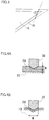
- Fig. 1 is a schematic sectional view showing the structure of a typical cutting edge of a cutting tool.
- the cutting edge is generally constituted of a flank 11 and a rake face 12 as shown in Fig. 1 , and the angle ⁇ formed by the flank 11 and the rake face 12 is acute or right in most cases.
- the thickness c of the forward end of the cutting edge enlarges as compared with the thicknesses a and b of the flank 11 and the rake face 12
- Figs. 2A to 2C are schematic sectional views showing progress of wear of the coating film of the cutting tool. Describing ideal wear progress on the cutting edge in the cutting tool having the aforementioned coating film 20, wear gradually progresses from the portion of the coating film 20 located on the forward end of the cutting edge and reaches the base 10 as shown in Fig. 2C , to thereafter wear down the base 10 along with the coating film 20 while exposing the base 10 as shown in Fig. 2C .
- Fig. 3 is a schematic sectional view showing a chipped state of the cutting tool.
- an object of the present invention is to provide a surface-coated cutting tool excellent in oxidation resistance and wear resistance and improved in fracture resistance and chipping resistance of a coating film to attain excellent cutting performance.
- a surface-coated cutting tool comprises the features of claim 1.
- the base is constituted of any of WC-based cemented carbide, cermet, high-speed steel, ceramics, a cubic boron nitride sintered body, a diamond sintered body, a silicon nitride sintered body and a sintered body containing aluminum oxide and titanium carbide.
- the surface-coated cutting tool is any of a drill, an end mill, a cutting edge-replaceable insert for milling, a cutting edge-replaceable insert for turning, a metal saw, a gear cutting tool, a reamer and a tap.
- the coating film is applied by physical vapor deposition.
- the physical vapor deposition is arc ion plating or magnetron sputtering.
- the inventive surface-coated cutting tool as hereinabove described, a specific effect of excellent fracture resistance and chipping resistance can be attained not only by high hardness and excellent wear resistance but also by having specific elastic recovery. Therefore, the inventive tool can effectively inhibit the base from being fractured along with the coating film in initial cutting. In the inventive tool, therefore, the coating film is hardly separated or chipped also in high-speed cutting or dry cutting with no coolant, and the tool life can be improved.
- the present invention is particularly suitable for cutting such as high-speed/dry cutting, interrupted cutting or heavy cutting under cutting conditions increasing the temperature of the cutting edge.
- the aforementioned object is attained by defining a specific property, more specifically elastic recovery, in addition to definition of the composition, the thickness and the hardness of a coating film provided on a base.
- the present invention provides a surface-coated cutting tool according to claim 1.
- the elastic recovery is particularly defined in the hard layer. (hmax - hf)/hmax is utilized as the elastic recovery assuming that hmax represents the maximum indentation depth and hf represents the indentation depth (dent depth) after unloading in the hardness test according to nanoindentation.
- the hard layer may be a singe layer or a multiple layer. It is assumed that the hard layer satisfies the aforementioned requirements for (a) the definition of the elastic recovery, (b) the thickness and (c) the hardness.
- the hard layer is a multiple layer, the total thickness may satisfy the aforementioned requirement (b), and a layer positioned on a specific depth with respect to the overall hard layer may satisfy the aforementioned requirements (a) and (c). More specifically, assuming that the dent depth of an indenter for nanoindentation is about 1/10 of the total thickness, for example, a layer positioned on this depth may satisfy the aforementioned requirements (a) and (c).
- the nanoindentation which is a kind of hardness test (refer to " Tribologist", Vol. 47, No. 3 (2002), pp. 177 to 183 ), is a technique (hereinafter referred to as a technique 1) of obtaining hardness from the relation between an indentation load on an indenter and a depth dissimilarly to a technique (hereinafter referred to as a technique 2) of obtaining hardness from a dent shape after indenter indentation performed in conventional Knoop hardness measurement or Vickers hardness measurement.
- a technique 1 of obtaining hardness from the relation between an indentation load on an indenter and a depth dissimilarly to a technique (hereinafter referred to as a technique 2) of obtaining hardness from a dent shape after indenter indentation performed in conventional Knoop hardness measurement or Vickers hardness measurement.
- the indentation depth of the indenter 30 is desirably set to not more than 100 nm. According to the technique 2, however, the size W of the dent is observed with an optical microscope, and hence it is difficult to precisely measure the dent shape when performing the aforementioned indentation.
- the indentation depth h ( Fig. 4A ) can be precisely measured due to mechanical measurement also when the indentation depth of the indenter 30 is set to not more than about 1/10 of the thickness of the coating film 20.
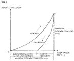
- Fig. 5 is a conceptual graph showing the relation between an indentation load P and an indentation depth h in a case of plunging an indenter into the surface of a coating film by nanoindentation.
- the indentation depth is measured by gradually increasing the load on the indenter up to the maximum load and performing unloading up to zero after reaching the maximum load Pmax in general.
- the technique 1 on the other hand, not only the dent depth h after unloading but also the maximum indentation depth hmax upon indentation of the indenter is measured.
- the inventors define (hmax - hf)/hmax as an index showing the elastic recovery since the elastic recovery of the coating film is obtained from the difference hmax - hf between the maximum indentation depth hmax and the dent depth hf after unloading.
- the coating film is easily elastically deformed but the softness thereof is so excessive that the wear resistance may be deteriorated if the aforementioned elastic recovery is large, while the coating film is increased in hardness to exhibit excellent wear resistance but the same is so hardly elastically deformed that fracture or chipping easily results from a shock in cutting if the elastic recovery is small. Therefore, the lower limit is set to 0.2 as the elastic recovery effective for improving the fracture resistance and the chipping resistance, and the upper limit is set to 0.7 as the elastic recovery necessary for attaining excellent wear resistance. More preferable elastic recovery is at least 0.3 and not more than 0.65.
- the elastic recovery is also influenced by the hardness as hereinabove described, and hence the hardness of the hard layer measured by nanoindentation is at least 20 GPa and not more than 80 GPa in order to obtain a cutting tool excellent in both of wear resistance and chipping resistance (fracture resistance).
- the hardness measured by nanoindentation is defined as described above. More preferable hardness is at least 25 GPa and not more than 60 GPa, more preferably at least 25 GPa and not more than 50 GPa, and further preferably at least 25 GPa and not more than 40 GPa. Particularly in working such as continuous turning receiving a small number of repetitive shocks, a film having higher hardness is preferably excellent in wear resistance.
- the hardness can be controlled by changing the composition under the same film forming conditions (temperature, gas pressure, bias voltage etc.), for example.
- the hardness can be controlled by changing the film forming conditions, more specifically, the temperature, the gas pressure, the bias voltage etc. in film formation.
- the bias voltage of a substrate is increased beyond a conventional level, for example. More specifically, the bias voltage is preferably set to -250 to -450 V.
- the bias voltage of the substrate is set high, incident energy of ions is so increased that the number of lattice defects introduced into the film surface in film formation is increased and remarkable strain remains in crystals constituting the film. Thus, residual stress is so increased that the hardness of the film can be conceivably improved as a result.
- the indentation load is applied in a state controlling the indentation depth of the indenter to not more than 1/10 of the film thickness in the hardness test according to nanoindentation, not to be influenced by the base provided under the coating film.
- the hardness is measured according to nanoindentation in the aforementioned hardness test controlling the indentation load.
- the indentation load can be controlled by a well-known nanoindentation apparatus.
- the thickness of the hard layer is set to at least 0.5 ⁇ m and not more than 15 ⁇ m. No improvement of the wear resistance is recognized if the thickness is less than 0.5 ⁇ m, while residual stress in the hard layer is increased to unpreferably reduce adhesion strength with respect to the base if the thickness exceeds 15 ⁇ m. More preferably, the thickness is at least 1.0 ⁇ m and not more than 7.0 ⁇ m. In measurement, the thickness can be obtained by cutting the cutting tool and observing the section thereof with an SEM (scanning electron microscope), for example. Further, the thickness can be changed by varying the film forming time.
- SEM scanning electron microscope
- a cubic Al compound exhibiting a metastable phase under the ordinary temperature and ordinary pressure can be formed.
- AlN which is hexagonal in general, exhibits an estimated lattice constant of 4.12 ⁇ when converted to the cubic metastable phase.
- CrN or VN exhibiting a cubic stable phase under the ordinary temperature and ordinary pressure has a lattice constant of 4.14 ⁇ , which is extremely close to the lattice constant of the aforementioned cubic AlN. Therefore, AlN is converted from the hexagonal state to the cubic state and improved in hardness due to the so-called ssen effect.
- the film containing Cr or V can be improved in hardness to have excellent wear resistance due to the cubic crystal structure of the film. Therefore, the content of Cr or V is set to 0 ⁇ a ⁇ 0.4 or 0 ⁇ b ⁇ 0.4 (where a + b ⁇ 0). If the content a or b exceeds 0.4, there is a possibility that the film hardness is contrarily reduced to cause reduction of the wear resistance.
- the hard layer contains V, the film surface is oxidized due to high-temperature environment in cutting, while such an effect can be expected that an oxide of V having a low melting point functions as a lubricant in cutting to suppress deposition of the workpiece.
- Cr is preferably added but not excessively introduced, more preferably in the ranges of 0 ⁇ a ⁇ 0.4, 0 ⁇ b ⁇ 0.4 and 0 ⁇ a + b ⁇ 0.4.
- the fine structure of the film is refined from a columnar structure of 200 to 500 nm to an acicular structure of not more than 100 nm, to contribute to improvement of the film hardness. If the Si content is excessive, on the other hand, the film is so easily embrittled that the alloy target may be cracked during preparation with no material strength capable of withstanding employment for film formation. Therefore, the Si content is set to 0 ⁇ c ⁇ 0.2.
- the fine structure can be checked by TEM (transmission electron microscope) observation, for example.
- the coating film further comprises an intermediate layer between the base surface and the hard layer.
- the intermediate layer is constituted of any of a nitride of Ti (reference example), a nitride of Cr (present invention), Ti (reference example) and Cr (present invention)
- the aforementioned element or nitride having excellent adhesiveness with respect to both of the hard layer and the base, can preferably further lengthen the tool life by further improving adhesion and effectively preventing the hard layer from separating from the base.
- the thickness of the intermediate layer is at least 0.005 ⁇ m and not more than 0.5 ⁇ m.
- Both of the hard layer and the intermediate layer may have the same composition.
- the film constituting the hard layer may satisfy the aforementioned conditions (a) to (c).
- Ti and Cr are brought into extremely active states due to incident energy of ions into the base to cause diffusion of atoms in the base and the coating film so that the intermediate layer containing Ti and Cr can exhibit an excellent function as an adhesion layer. Therefore, the hard coating layer can be inhibited from separating from the base as compared with a case of having no intermediate layer containing no Ti or Cr, whereby the wear resistance of the cutting tool is so improved that the cutting life can be elongated.
- the intermediate layer containing Ti or Cr, lower in hardness as compared with the hard coating layer, also has a function of absorbing a shock on the cutting edge in starting of cutting, and can also suppress fracture of the cutting edge caused in initial cutting.
- the coating film may comprise a film of a carbide or a carbonitride as the outermost layer. More specifically, TiC, TiCN, TiSiCN and TiAlCN can be listed. When the inventors have investigated to evaluate a seizing state of a workpiece of a ferrous material such as steel by a pin-on-disc test at a specimen temperature of 800°C, seizing was hardly recognized and frictional resistance was reduced in a cutting tool comprising a film of a carbide or a carbonitride as the outermost layer, although the detailed mechanism has not yet been recognized. Thus, a film of a carbide or a carbonitride provided as the outermost layer conceivably reduces the cutting resistance to contribute to extension of the tool life.
- the aforementioned coating film comprising the hard layer, the intermediate layer and the outermost layer is suitably prepared through a film forming process capable of forming a compound having high crystallinity.
- a film forming process capable of forming a compound having high crystallinity.
- the inventors have recognized that it is preferable to employ physical vapor deposition.
- the physical vapor deposition balanced magnetron sputtering, unbalanced magnetron sputtering, ion plating or the like can be listed, for example In particular, arc ion plating (cathode arc ion plating) having a high ionization degree for raw material elements is optimum.
- the average particle diameter is preferably set to at least 2 nm and not more than 100 nm.
- performance of quenching after film formation in the aforementioned film forming method can be listed, for example.
- annealing is generally performed after film formation.
- fine crystal grains are obtained although not completely understood, and the aforementioned specific elastic recovery is conceivably attained in the case of such a fine structure.
- an operation of employing a base holder allowing water cooling and water-cooling the base holder can be listed, for example.
- the base is preferably made of one material selected from WC-based cemented carbide, cermet, high-speed steel, ceramics, a cubic boron nitride (cBN) sintered body, a diamond sintered body, a silicon nitride sintered body and a sintered body containing aluminum oxide and titanium carbide.
- cBN cubic boron nitride
- WC-based cemented carbide that consisting of a hard phase mainly composed of tungsten carbide (WC) and a bonded phase mainly composed of an iron group metal such as cobalt (Co) and frequently employed in general may be employed. Further, that containing a solid solution composed of at least one selected from the transition metal elements belonging to the groups 4a, 5a and 6a of the periodic table and at least one selected from carbon, nitrogen, oxygen and boron may also be employed.
- (Ta,Nb)C, VC, Cr 2 C 2 or NbC can be listed, for example.
- cermet that consisting of a solid solution phase composed of at least one selected from the transition metal elements belonging to the groups 4a, 5a and 6a of the periodic table and at least one selected from carbon, nitrogen, oxygen and boron
- a bonded layer composed of at least one ferrous metal and unavoidable impurities and frequently employed in general may be employed.
- W-based high-speed steel such as SKH2, SKH5 or SKH10 under JIS or Mo-based high-speed steel such as SKH9, SKH52 or SKH56 can be listed, for example.
- silicon carbide, silicon nitride, aluminum nitride or aluminum oxide can be listed, for example.
- cBN sintered body that containing at least 30 volume % of cBN can be listed. More specifically, the following sintered bodies can be listed:
- the cBN particles can be bonded to each other and the content of the cBN particles can be increased by performing liquid phase sintering with a starting material of a metal containing Al or Co having a catalytic action or an intermetallic compound. While the wear resistance is easily reduced due to the high content of the cBN particles, the cBN particles form such a strong skeleton structure that the cutting tool is excellent in fracture resistance and capable of cutting under severe conditions.
- the cBN content is set to at least 80 volume % since it is difficult to form the skeleton structure by bonding the cBN particles to each other if the cBN content is less than 80 volume %.
- the cBN content is set to not more than 90 volume % since unsintered portions are formed due to insufficiency of the aforementioned binder having the catalytic action to result in reduction of the strength of the cBN sintered body if the cBN content exceeds 90 volume %.
- the diamond sintered body that containing at least 40 volume % of diamond can be listed. More specifically, the following sintered bodies can be listed:
- the silicon nitride sintered body that containing at least 90 volume % of silicon nitride can be listed.
- a sintered body containing at least 90 volume % of silicon nitride bonded through HIP (hot isostatic pressing sintering) is preferable.
- the rest preferably consists of a binder composed of at least one selected from aluminum oxide, aluminum nitride, yttrium oxide, magnesium oxide, zirconium oxide, hafnium oxide, rare earth, TiN and TiC and unavoidable impurities.
- the sintered body containing aluminum oxide and titanium carbide a sintered body containing at least 20 % and 80 % by volume of aluminum oxide and at least 15 % and not more than 75 % by volume of titanium carbide with the rest consisting of at least one binder selected from oxides of Mg, Y, Ca, Zr, Ni, Ti and TiN and unavoidable impurities.
- the content of aluminum oxide is at least 65 volume % and not more than 70 volume %
- the content of titanium carbide is at least 25 volume % and not more than 30 volume %
- the binder is at least one selected from oxides of Mg, Y and Ca.
- the tool according to the present invention is one selected from a drill, an end mill, a cutting edge-replaceable insert for milling, a cutting edge-replaceable insert for turning, a metal saw, a gear cutting tool, a reamer and a tap.
- the following surface-coated cutting tools were prepared for investigation of wear resistance.
- Each base prepared from cemented carbide of grade P30 under JIS having an insert shape SPGN120308 under JIS was mounted on a base holder of a well-known cathode arc ion plating apparatus.
- As the base holder that allowing water cooling was employed.
- the internal pressure of a chamber was reduced and the insert-shaped base was heated to a temperature of 650°C with a heater set in the apparatus while rotating the base holder, and the chamber was evacuated until the internal pressure reached 1.0 ⁇ 10 -4 Pa.
- argon gas was introduced into the chamber for holding the internal pressure of the chamber at 3.0 Pa, and the voltage of a base bias power source was gradually increased up to 1500 V, for cleaning the base surface for 15 minutes.
- the argon gas was discharged from the chamber.
- alloy targets serving as metal evaporation sources for coating film components were arranged and gas for obtaining desired coating films was introduced from among nitrogen, methane and oxygen, for supplying an arc current of 100 A to a cathode while maintaining the substrate temperature, the reaction gas pressure and the base bias voltage at 650°C, 2.0 Pa and -200 V respectively for samples 1 to 29, 51 and 52 and maintaining the base bias voltage, the reaction gas pressure and the base bias voltage at 650°C, 2.0 Pa and -350 V respectively for samples 30 to 32, for generating metallic ions from the arc evaporation sources and forming coating films.
- the current supplied to the evaporation sources was stopped when prescribed film thicknesses were obtained.
- coating was ended by stopping the aforementioned current in the samples 1 to 32 and He gas was introduced to fill up the chamber at the same time while the samples were quenched by water-cooling the base holders.
- the samples 51 and 52 were ordinarily annealed.
- the film thicknesses were varied with film forming times.
- respective coating layers were formed under similar conditions, with hardness levels varied with compositions.
- Samples comprising films of Ti as intermediate layers were formed with introduction of argon gas in film formation.
- the coating films, formed by cathode arc ion plating in this Example can alternatively be formed by another technique such as balanced magnetron sputtering or unbalanced magnetron sputtering, for example.
- Table 1 shows the types and thicknesses of the coating films of the respective samples.
- Hardness levels of hard layers were measured by nanoindentation.
- Table 2 shows measured hardness levels, maximum indentation depths hmax and elastic recovery values (hmax - hf)/hmax (where hf represents dent depth).
- Hardness measurement according to nanoindentation was performed by controlling an indentation load so that the indentation depth of an indenter was not more than 1/10 of the film thickness with respect to each hard layer. This measurement was performed with a nano indenter (Nano Indenter XP by MTS). While all of the samples 1 to 32 exhibited fine structures with average particle diameters of 2 to 100 nm when the crystal grain sizes thereof were investigated through TEM observation, the samples 51 and 52 exhibited average particle diameters of 200 to 500 nm. In particular, the hard layers containing Si exhibited smaller values among the aforementioned average particle diameters, and had fine acicular structures. Table 1 Sample No.
- samples 1 to 34 those comprising intermediate layers of any of Ti, Cr, TiN and CrN were particularly excellent in adhesiveness.
- those having hard layers of carbonitrides caused less seizure on workpieces than the samples 7, 12 and 23 having hard layers of an oxynitride and carboxynitrides respectively.
- the cutting resistance was reduced.
- those containing at least one of B, Mg, Ca, V, Cr, Zn and Zr were higher in hardness as compared with the remaining samples.
- even those having hard layers containing no Ti are excellent in cutting performance as shown in the samples 18 to 29 and 3 1 to 34.
- Drills comprising coating films were obtained by preparing a plurality of bases of drills (cemented carbide K10 under JIS) having outer diameters of 8 mm and forming coating films on the bases respectively.
- the coating films were provided similarly to those of the samples 2, 11, 16, 19, 32, 51 and 52 in the aforementioned Example 1. These drills comprising the coating films were employed for drilling SCM440 (H R C30), and the tool lives were evaluated.
- the cutting conditions were a cutting speed of 90 m/min. a feed rate of 0.2 mm/rev., employment of no coolant (using air blow) and blind hole cutting of 24 mm in depth.
- the tool life of each sample was determined when the dimensional accuracy of a workpiece was out of a defined range and evaluated with the number of holes formed before the end of the life. Table 5 shows the results. Table 5 Sample 2-2 Sample 2-11 Sample 2-16 Sample 2-19 Sample 2-32 Sample 2.51 Sample 2-52 Film Type Working Content Life Criterion Sample 2 Sample 11 Sample 16 Sample 19 Sample 32 Sample 51 Sample 52 Drilling Number of Works (holes) 5,600 7,600 4,900 8500 9,800 1,050 1,100
- End mills comprising coating films were obtained by preparing a plurality of bases of six-flute end mills (cemented carbide K10 under JIS) having outer diameters of 8 mm and coating films were formed on the bases respectively by a method similar to that in Example 1.
- the coating films were prepared similarly to those of the samples 2, 11, 16, 19, 32, 51 and 52 in the aforementioned Example 1. These end mills comprising the coating films were employed for end mill side cutting of SKD 11 (H R C60), and the tool lives were evaluated.
- the cutting conditions were a cutting speed of 200 m/min., a feed rate of 0.03 mm/edge, a depth of cut Ad of 12 mm, Rd of 0.2 mm and employment of no coolant (using air blow).
- the tool life of each sample was determined when the dimensional accuracy of a workpiece was out of a defined range and evaluated with the cutting length before the end of the life. Table 6 shows the results. Table 6 Sample 3-2 Sample 3-11 Sample 3-16 Sample 3-19 Sample 3-32 Sample 3-51 Sample 3-52 Film Type Working Content Life Criterion Sample 2 Sample 11 Sample 16 Sample 19 Sample 32 Sample 51 Sample 52 End Mill Side Cutting Length Out Of Dimensional Accuracy 145m 160m 140m 230m 165m 21m 28m
- Cutting inserts were prepared by employing cBN sintered bodies for bases, for performing cutting with these cutting inserts and evaluating tool lives.
- Each cBN sintered body was obtained by mixing binder powder consisting of 40 mass % of TiN and 10 mass % of Al with 50 mass % of cBN powder having an average particle diameter of 2.5 ⁇ m in a cemented carbide pot and balls, charging the mixture into a cemented carbide container and sintering the same under a pressure of 5 GPa and a temperature of 1400°C for 60 minutes.
- This cBN sintered body was worked into a cutting insert base having a shape SNGA120408 under ISO. A plurality of such insert bases were prepared.
- Coating films were formed on these insert bases respectively by a method similar to that in Example 1, for obtaining cutting inserts comprising the coating films.
- the coating films were provided similarly to those of the samples 2, 11, 16, 19, 32, 51 and 52 of the aforementioned Example 1
- These cutting inserts comprising the coating films were employed for peripheral milling of SUJ2, a kind of hardened steel, and frank wear widths (Vb) were measured.
- Cutting conditions were a cutting speed of 120 m/min., a depth of cut of 0.2 mm, a feed rate of 0.1 mm/rev and a dry condition, and cutting was performed for 30 minutes. Table 7 shows the results. Table 7 Sample 4-2 Sample 4-11 Sample 4-16 Sample 4-19 Sample 4-32 Sample 4-51 Sample 4-52 Film Type Working Content Sample 2 Sample 11 Sample 16 Sample 19 Sample 32 Sample 51 Sample 52 Peripheral Turning Vb Abrasion Loss 0.109 mm 0.088 mm 0.097 mm 0.072 mm 0.082 mm 0.325 mm chipped
- samples 4-2, 4-11, 4-16, 4-19 and 4-32 were superior in wear resistance as well as fracture resistance and chipping resistance as compared with samples 4-51 and 4-52.
Description
- The present invention relates to a cutting tool comprising a coating film on a base surface. More particularly, it relates to a surface-coated cutting tool having excellent wear resistance, excellent in fracture resistance and chipping resistance, and capable of improving cutting performance.
- In general, a tool comprising a coating film of a nitride or a carbonitride of AlTiSi on a base surface of WC-based cemented carbide, cermet or high-speed steel in order to improve wear resistance and a surface protecting function is known as a cutting tool or a wear-resistant tool (refer to patent literature 1, for example).
- In response to the recent trends described below, however, the cutting edge temperature of a tool tends to increasingly rise in cutting, and characteristics required to tool materials are getting severer. For example,
- 1. dry working with no lubricant (coolant) is required in consideration of terrestrial environmental protection,
- 2. worked materials (workpieces) are diversified, and
- 3. the cutting speed is increased in order to further improve working efficiency, can be listed.
- In this regard, patent literature 2, for example, discloses that the performance of a cutting tool is improved also in dry high-speed cutting by providing a TiN film immediately on a base while providing a TiAlN film thereon and further providing a TiSiN film thereon. According to this patent, solving such a problem that intra-film diffusion of oxygen can be suppressed due to an alumina layer formed by oxidation of a film surface during cutting when a TiAl compound film is provided as a coating film while the alumina layer is so easily separated by a porous Ti oxide layer formed immediately under the alumina layer upon dynamic cutting that progress of oxidation cannot be sufficiently prevented in general, the aforementioned porous Ti oxide layer is not formed but improvement of performance is attained by providing a TiSi compound film having extremely high oxidation resistance with denseness on the film surface.
- Patent Document 1: Japanese Patent Laying-Open No.
7-310174 - Non-Patent Document 1: Japanese Patent Laying-Open No.
2000-326108 -
EP 1422 311 relates to a hard film and hard film coated tool formed by an arc-discharge ion-plating method.US 5580653 relates to a hard coating suitable for use as a surface coating for a wear resistant member.JP 09295204 US5580653 relates to a hard coating with good wear resistance made of AlTiSi carbonitrides compounds wherein the oxidation resistance is also ensured. The documentUS 2003/0148145 describes a hard wear resistant coating with compositions comprising AlCrV carbonitrides. - In order to perform high-speed/high-efficiency working or dry working without any lubricant, however, it is insufficient to take into consideration only safety of the coating film under the aforementioned high temperature. In other words, it is necessary to take into consideration how to keep a coating film excellent in characteristic on a base surface in excellent adhesiveness over a long period without causing separation or fracture.
-
Fig. 1 is a schematic sectional view showing the structure of a typical cutting edge of a cutting tool. In abase 10, the cutting edge is generally constituted of aflank 11 and arake face 12 as shown inFig. 1 , and the angle α formed by theflank 11 and therake face 12 is acute or right in most cases. When acoating film 20 is formed on the cutting edge of this shape, the thickness c of the forward end of the cutting edge enlarges as compared with the thicknesses a and b of theflank 11 and therake face 12 -
Figs. 2A to 2C are schematic sectional views showing progress of wear of the coating film of the cutting tool. Describing ideal wear progress on the cutting edge in the cutting tool having theaforementioned coating film 20, wear gradually progresses from the portion of thecoating film 20 located on the forward end of the cutting edge and reaches thebase 10 as shown inFig. 2C , to thereafter wear down thebase 10 along with thecoating film 20 while exposing thebase 10 as shown inFig. 2C . - However, the inventors have detailedly investigated the worn state of the cutting tool, to find that the wear did not progress as shown in the above
Figs. 2A to 2C but not only thecoating film 20 but also the forward end of the cutting edge of thebase 10 already disappeared in initial cutting as shown inFig. 3 to expose thebase 10, which has been recognized as being fractured from its configuration. Further, it has also been recognized that an exposed portion 13 was already oxidized in thebase 10. Thus, it is conceivably difficult to remarkably improve the tool life due to the exposure of the base in initial cutting, despite the coating film having excellent oxidation resistance described in the aforementioned patent literature 2.Fig. 3 is a schematic sectional view showing a chipped state of the cutting tool. - In a cutting tool used for high-speed working or dry working under severe conditions, therefore, it is important not only to improve oxidation resistance of a coating film as a matter of course but also to suppress fracture or chipping on a cutting edge caused in initial cutting, i.e., to suppress exposure of a base.
- Accordingly, an object of the present invention is to provide a surface-coated cutting tool excellent in oxidation resistance and wear resistance and improved in fracture resistance and chipping resistance of a coating film to attain excellent cutting performance.
- According to an aspect of the present invention, a surface-coated cutting tool comprises the features of claim 1.
- Preferably, the base is constituted of any of WC-based cemented carbide, cermet, high-speed steel, ceramics, a cubic boron nitride sintered body, a diamond sintered body, a silicon nitride sintered body and a sintered body containing aluminum oxide and titanium carbide.
- Preferably, the surface-coated cutting tool is any of a drill, an end mill, a cutting edge-replaceable insert for milling, a cutting edge-replaceable insert for turning, a metal saw, a gear cutting tool, a reamer and a tap.
- Preferably, the coating film is applied by physical vapor deposition.
- Preferably, the physical vapor deposition is arc ion plating or magnetron sputtering.
- According to the inventive surface-coated cutting tool, as hereinabove described, a specific effect of excellent fracture resistance and chipping resistance can be attained not only by high hardness and excellent wear resistance but also by having specific elastic recovery. Therefore, the inventive tool can effectively inhibit the base from being fractured along with the coating film in initial cutting. In the inventive tool, therefore, the coating film is hardly separated or chipped also in high-speed cutting or dry cutting with no coolant, and the tool life can be improved. The present invention is particularly suitable for cutting such as high-speed/dry cutting, interrupted cutting or heavy cutting under cutting conditions increasing the temperature of the cutting edge.
-
-
Fig. 1 is a schematic sectional view showing the structure of a typical cutting edge of a cutting tool. -
Fig. 2A is a schematic sectional view showing progress of wear of a coating film for the cutting tool, illustrating an initial cutting stage in an ideally worn state. -
Fig. 2B is a schematic sectional view showing the progress of wear of the coating film for the cutting tool, illustrating an intermediate cutting stage in the ideally worn state. -
Fig. 2C is a schematic sectional view showing the progress of wear of the coating film for the cutting tool, illustrating a final cutting stage in the ideally worn state. -
Fig. 3 is a schematic sectional view showing the state of an initial cutting stage of a conventional cutting tool. -
Fig. 4A is a model diagram illustrating the state of a hardness test, showing a hardness test according to nanoindentation. -
Fig. 4B is a model diagram illustrating the state of another hardness test, showing a micro Vickers hardness test. -
Fig. 5 is a conceptual graph showing the relation between an indentation load and an indentation depth in a case of plunging an indenter into the surface of a coating film by nanoindentation. - According to the present invention, the aforementioned object is attained by defining a specific property, more specifically elastic recovery, in addition to definition of the composition, the thickness and the hardness of a coating film provided on a base.
- In other words, the present invention provides a surface-coated cutting tool according to claim 1.
- In order to attain extension of the life of the cutting tool, it is important to improve fracture resistance and chipping resistance of the cutting edge, particularly the coating film. The inventors have made investigation, to recognize that fracture or chipping caused in initial cutting can be suppressed if the coating film can be deformed to some extent to follow a load applied to the cutting edge in cutting. In other words, the fracture resistance and the chipping resistance can be improved when the coating film has specific elastic recovery. According to the present invention, therefore, the elastic recovery is particularly defined in the hard layer. (hmax - hf)/hmax is utilized as the elastic recovery assuming that hmax represents the maximum indentation depth and hf represents the indentation depth (dent depth) after unloading in the hardness test according to nanoindentation. The present invention is now described in detail.
- The hard layer may be a singe layer or a multiple layer. It is assumed that the hard layer satisfies the aforementioned requirements for (a) the definition of the elastic recovery, (b) the thickness and (c) the hardness. When the hard layer is a multiple layer, the total thickness may satisfy the aforementioned requirement (b), and a layer positioned on a specific depth with respect to the overall hard layer may satisfy the aforementioned requirements (a) and (c). More specifically, assuming that the dent depth of an indenter for nanoindentation is about 1/10 of the total thickness, for example, a layer positioned on this depth may satisfy the aforementioned requirements (a) and (c).
- The nanoindentation is now described. The nanoindentation, which is a kind of hardness test (refer to "Tribologist", Vol. 47, No. 3 (2002), pp. 177 to 183), is a technique (hereinafter referred to as a technique 1) of obtaining hardness from the relation between an indentation load on an indenter and a depth dissimilarly to a technique (hereinafter referred to as a technique 2) of obtaining hardness from a dent shape after indenter indentation performed in conventional Knoop hardness measurement or Vickers hardness measurement. According to the technique 2, an indentation load on an
indenter 30 was so large as shown inFig. 4B that physical property evaluation of acoating film 20 was not that of only thecoating film 20 but influenced by a base 10 located under thecoating film 20. It is said that it is necessary to set the indentation depth of theindenter 30 to not more than about 1/10 of the thickness in order to measure the hardness of only thecoating film 20 with no influence by the base 10 provided under thecoating film 20. Assuming that the thickness of thecoating film 20 is 1 µm, for example, the indentation depth of theindenter 30 is desirably set to not more than 100 nm. According to the technique 2, however, the size W of the dent is observed with an optical microscope, and hence it is difficult to precisely measure the dent shape when performing the aforementioned indentation. According to the technique 1, on the other hand, the indentation depth h (Fig. 4A ) can be precisely measured due to mechanical measurement also when the indentation depth of theindenter 30 is set to not more than about 1/10 of the thickness of thecoating film 20. -
Fig. 5 is a conceptual graph showing the relation between an indentation load P and an indentation depth h in a case of plunging an indenter into the surface of a coating film by nanoindentation. According to the technique 2, the indentation depth is measured by gradually increasing the load on the indenter up to the maximum load and performing unloading up to zero after reaching the maximum load Pmax in general. According to the technique 1, on the other hand, not only the dent depth h after unloading but also the maximum indentation depth hmax upon indentation of the indenter is measured. The inventors define (hmax - hf)/hmax as an index showing the elastic recovery since the elastic recovery of the coating film is obtained from the difference hmax - hf between the maximum indentation depth hmax and the dent depth hf after unloading. - The coating film is easily elastically deformed but the softness thereof is so excessive that the wear resistance may be deteriorated if the aforementioned elastic recovery is large, while the coating film is increased in hardness to exhibit excellent wear resistance but the same is so hardly elastically deformed that fracture or chipping easily results from a shock in cutting if the elastic recovery is small. Therefore, the lower limit is set to 0.2 as the elastic recovery effective for improving the fracture resistance and the chipping resistance, and the upper limit is set to 0.7 as the elastic recovery necessary for attaining excellent wear resistance. More preferable elastic recovery is at least 0.3 and not more than 0.65.
- The elastic recovery is also influenced by the hardness as hereinabove described, and hence the hardness of the hard layer measured by nanoindentation is at least 20 GPa and not more than 80 GPa in order to obtain a cutting tool excellent in both of wear resistance and chipping resistance (fracture resistance). According to the present invention, therefore, the hardness measured by nanoindentation is defined as described above. More preferable hardness is at least 25 GPa and not more than 60 GPa, more preferably at least 25 GPa and not more than 50 GPa, and further preferably at least 25 GPa and not more than 40 GPa. Particularly in working such as continuous turning receiving a small number of repetitive shocks, a film having higher hardness is preferably excellent in wear resistance. The hardness can be controlled by changing the composition under the same film forming conditions (temperature, gas pressure, bias voltage etc.), for example. When the composition remains intact, the hardness can be controlled by changing the film forming conditions, more specifically, the temperature, the gas pressure, the bias voltage etc. in film formation. In order to attain high hardness of at least 50 GPa, in particular, the bias voltage of a substrate is increased beyond a conventional level, for example. More specifically, the bias voltage is preferably set to -250 to -450 V. When the bias voltage of the substrate is set high, incident energy of ions is so increased that the number of lattice defects introduced into the film surface in film formation is increased and remarkable strain remains in crystals constituting the film. Thus, residual stress is so increased that the hardness of the film can be conceivably improved as a result.
- According to the present invention, it is assumed that the indentation load is applied in a state controlling the indentation depth of the indenter to not more than 1/10 of the film thickness in the hardness test according to nanoindentation, not to be influenced by the base provided under the coating film. According to the present invention, further, it is assumed that the hardness is measured according to nanoindentation in the aforementioned hardness test controlling the indentation load. The indentation load can be controlled by a well-known nanoindentation apparatus.
- The thickness of the hard layer is set to at least 0.5 µm and not more than 15 µm. No improvement of the wear resistance is recognized if the thickness is less than 0.5 µm, while residual stress in the hard layer is increased to unpreferably reduce adhesion strength with respect to the base if the thickness exceeds 15 µm. More preferably, the thickness is at least 1.0 µm and not more than 7.0 µm. In measurement, the thickness can be obtained by cutting the cutting tool and observing the section thereof with an SEM (scanning electron microscope), for example. Further, the thickness can be changed by varying the film forming time.
- When the hard layer contains at least either Cr or V, a cubic Al compound exhibiting a metastable phase under the ordinary temperature and ordinary pressure can be formed. With reference to a nitride, for example, AlN, which is hexagonal in general, exhibits an estimated lattice constant of 4.12 Å when converted to the cubic metastable phase. On the other hand, CrN or VN exhibiting a cubic stable phase under the ordinary temperature and ordinary pressure has a lattice constant of 4.14 Å, which is extremely close to the lattice constant of the aforementioned cubic AlN. Therefore, AlN is converted from the hexagonal state to the cubic state and improved in hardness due to the so-called ziehen effect. In other words, the film containing Cr or V can be improved in hardness to have excellent wear resistance due to the cubic crystal structure of the film. Therefore, the content of Cr or V is set to 0 ≤ a ≤ 0.4 or 0 ≤ b ≤ 0.4 (where a + b ≠ 0). If the content a or b exceeds 0.4, there is a possibility that the film hardness is contrarily reduced to cause reduction of the wear resistance. When the hard layer contains V, the film surface is oxidized due to high-temperature environment in cutting, while such an effect can be expected that an oxide of V having a low melting point functions as a lubricant in cutting to suppress deposition of the workpiece. When the hard layer contains Cr, such an effect can be expected that an oxide of Cr formed by surface oxidation during cutting densifies the oxide of Al to improve the film hardness. In order to further improve the wear resistance, therefore, Cr is preferably added but not excessively introduced, more preferably in the ranges of 0 ≤ a ≤ 0.4, 0 ≤ b ≤ 0.4 and 0 < a + b ≤ 0.4.
- When the hard layer contains Si, the fine structure of the film is refined from a columnar structure of 200 to 500 nm to an acicular structure of not more than 100 nm, to contribute to improvement of the film hardness. If the Si content is excessive, on the other hand, the film is so easily embrittled that the alloy target may be cracked during preparation with no material strength capable of withstanding employment for film formation. Therefore, the Si content is set to 0 ≤ c ≤ 0.2. The fine structure can be checked by TEM (transmission electron microscope) observation, for example.
- In order to improve adhesiveness between the aforementioned hard layer and the base, the coating film further comprises an intermediate layer between the base surface and the hard layer. Particularly when the intermediate layer is constituted of any of a nitride of Ti (reference example), a nitride of Cr (present invention), Ti (reference example) and Cr (present invention), the aforementioned element or nitride, having excellent adhesiveness with respect to both of the hard layer and the base, can preferably further lengthen the tool life by further improving adhesion and effectively preventing the hard layer from separating from the base. The thickness of the intermediate layer is at least 0.005 µm and not more than 0.5 µm. Improvement of adhesive strength is hardly obtained if the thickness is less than 0.005 µm, while no further improvement of adhesion is recognized if the thickness exceeds 0.5 µm. Both of the hard layer and the intermediate layer may have the same composition. At this time, the film constituting the hard layer may satisfy the aforementioned conditions (a) to (c). Particularly when the film is formed by PVD, Ti and Cr are brought into extremely active states due to incident energy of ions into the base to cause diffusion of atoms in the base and the coating film so that the intermediate layer containing Ti and Cr can exhibit an excellent function as an adhesion layer. Therefore, the hard coating layer can be inhibited from separating from the base as compared with a case of having no intermediate layer containing no Ti or Cr, whereby the wear resistance of the cutting tool is so improved that the cutting life can be elongated.
- The intermediate layer containing Ti or Cr, lower in hardness as compared with the hard coating layer, also has a function of absorbing a shock on the cutting edge in starting of cutting, and can also suppress fracture of the cutting edge caused in initial cutting.
- In addition, the coating film may comprise a film of a carbide or a carbonitride as the outermost layer. More specifically, TiC, TiCN, TiSiCN and TiAlCN can be listed. When the inventors have investigated to evaluate a seizing state of a workpiece of a ferrous material such as steel by a pin-on-disc test at a specimen temperature of 800°C, seizing was hardly recognized and frictional resistance was reduced in a cutting tool comprising a film of a carbide or a carbonitride as the outermost layer, although the detailed mechanism has not yet been recognized. Thus, a film of a carbide or a carbonitride provided as the outermost layer conceivably reduces the cutting resistance to contribute to extension of the tool life.
- The aforementioned coating film comprising the hard layer, the intermediate layer and the outermost layer is suitably prepared through a film forming process capable of forming a compound having high crystallinity. As a result of studying various film forming methods, the inventors have recognized that it is preferable to employ physical vapor deposition. As the physical vapor deposition, balanced magnetron sputtering, unbalanced magnetron sputtering, ion plating or the like can be listed, for example In particular, arc ion plating (cathode arc ion plating) having a high ionization degree for raw material elements is optimum. When cathode arc ion plating is employed, metal ion bombardment processing is possible with respect to the base surface before formation of the coating film, whereby adhesiveness of the coating film can be remarkably improved, and this is a preferable process also in consideration of adhesiveness.
- In order to form the hard layer having the aforementioned specific elastic recovery, refinement of crystal grains in the hard layer can be listed. More preferably, the average particle diameter is preferably set to at least 2 nm and not more than 100 nm. As a method of refining crystal grains, performance of quenching after film formation in the aforementioned film forming method can be listed, for example. In film formation by physical vapor deposition, annealing is generally performed after film formation. When not annealing but quenching is performed, on the other hand, fine crystal grains are obtained although not completely understood, and the aforementioned specific elastic recovery is conceivably attained in the case of such a fine structure. As the quenching, an operation of employing a base holder allowing water cooling and water-cooling the base holder can be listed, for example. An operation of controlling the film composition as described above, more specifically introducing a proper quantity of Si, also contributes to the refinement.
- According to the present invention, the base is preferably made of one material selected from WC-based cemented carbide, cermet, high-speed steel, ceramics, a cubic boron nitride (cBN) sintered body, a diamond sintered body, a silicon nitride sintered body and a sintered body containing aluminum oxide and titanium carbide.
- As the WC-based cemented carbide, that consisting of a hard phase mainly composed of tungsten carbide (WC) and a bonded phase mainly composed of an iron group metal such as cobalt (Co) and frequently employed in general may be employed. Further, that containing a solid solution composed of at least one selected from the transition metal elements belonging to the groups 4a, 5a and 6a of the periodic table and at least one selected from carbon, nitrogen, oxygen and boron may also be employed. As the solid solution, (Ta,Nb)C, VC, Cr2C2 or NbC can be listed, for example.
- As the cermet, that consisting of a solid solution phase composed of at least one selected from the transition metal elements belonging to the groups 4a, 5a and 6a of the periodic table and at least one selected from carbon, nitrogen, oxygen and boron, a bonded layer composed of at least one ferrous metal and unavoidable impurities and frequently employed in general may be employed.
- As the high-speed steel, W-based high-speed steel such as SKH2, SKH5 or SKH10 under JIS or Mo-based high-speed steel such as SKH9, SKH52 or SKH56 can be listed, for example.
- As to the ceramics, silicon carbide, silicon nitride, aluminum nitride or aluminum oxide can be listed, for example.
- As the cBN sintered body, that containing at least 30 volume % of cBN can be listed. More specifically, the following sintered bodies can be listed:
- (1) A sintered body containing at least 30 volume % and not more than 80 volume % of cBN with the rest consisting of a binder, an iron group metal and unavoidable impurities. The binder contains at least one selected from a group consisting of nitrides, borides and carbides of the elements belonging to the groups 4a, 5a and 6a of the periodic table and solid solutions thereof and an aluminum compound.
In the aforementioned cBN sintered body, cBN particles, mainly bonded through the aforementioned binder having low affinity to iron frequently employed as a workpiece in strong binding, improve the wear resistance and the strength of the base. The cBN content is set to at least 30 volume % since the hardness of the cBN sintered body is so easily reduced that the hardness is insufficient for cutting a workpiece such as hardened steel, for example, having high hardness if the cBN content is less than 30 volume %. The cBN content is set to not more than 80 volume % since it is so difficult to bond the cBN particles to each other through the binder if the cBN content exceeds 80 volume %, leading to a possibility of reducing the strength of the cBN sintered body. - (2) A sintered body containing at least 80 volume % and not more than 90 volume % of cBN with cBN particles bonded to each other, with the rest consisting of a binder and unavoidable impurities. The binder is mainly composed of an Al compound or a Co compound.
- In this cBN sintered body, the cBN particles can be bonded to each other and the content of the cBN particles can be increased by performing liquid phase sintering with a starting material of a metal containing Al or Co having a catalytic action or an intermetallic compound. While the wear resistance is easily reduced due to the high content of the cBN particles, the cBN particles form such a strong skeleton structure that the cutting tool is excellent in fracture resistance and capable of cutting under severe conditions. The cBN content is set to at least 80 volume % since it is difficult to form the skeleton structure by bonding the cBN particles to each other if the cBN content is less than 80 volume %. The cBN content is set to not more than 90 volume % since unsintered portions are formed due to insufficiency of the aforementioned binder having the catalytic action to result in reduction of the strength of the cBN sintered body if the cBN content exceeds 90 volume %.
- As the diamond sintered body, that containing at least 40 volume % of diamond can be listed. More specifically, the following sintered bodies can be listed:
- (1) A sintered body containing 50 to 98 volume % of diamond with the rest consisting of an iron group metal, WC and unavoidable impurities. As the iron group metal, Co is particularly preferable.
- (2) A sintered body containing 85 to 99 volume % of diamond with the rest consisting of holes, WC and unavoidable impurities.
- (3) A sintered body containing 60 to 95 volume % of diamond with the rest consisting of a binder and unavoidable impurities. The binder contains an iron group metal, at least one selected from a group consisting of carbides and carbonitrides of the elements belonging to the groups 4a, 5a and 6a of the periodic table and WC. A more preferable binder contains Co, TiC and WC.
- (4) A sintered body containing at least 60 to 98 volume % of diamond with the rest consisting of at least either silicon or silicon carbide, WC and unavoidable impurities.
- As the silicon nitride sintered body, that containing at least 90 volume % of silicon nitride can be listed. In particular, a sintered body containing at least 90 volume % of silicon nitride bonded through HIP (hot isostatic pressing sintering) is preferable. In this sintered body, the rest preferably consists of a binder composed of at least one selected from aluminum oxide, aluminum nitride, yttrium oxide, magnesium oxide, zirconium oxide, hafnium oxide, rare earth, TiN and TiC and unavoidable impurities.
- As the sintered body containing aluminum oxide and titanium carbide, a sintered body containing at least 20 % and 80 % by volume of aluminum oxide and at least 15 % and not more than 75 % by volume of titanium carbide with the rest consisting of at least one binder selected from oxides of Mg, Y, Ca, Zr, Ni, Ti and TiN and unavoidable impurities. In particular, it is preferable that the content of aluminum oxide is at least 65 volume % and not more than 70 volume %, the content of titanium carbide is at least 25 volume % and not more than 30 volume %, and the binder is at least one selected from oxides of Mg, Y and Ca.
- It is listable to assume that the tool according to the present invention is one selected from a drill, an end mill, a cutting edge-replaceable insert for milling, a cutting edge-replaceable insert for turning, a metal saw, a gear cutting tool, a reamer and a tap.
- The following surface-coated cutting tools were prepared for investigation of wear resistance.
- Each base prepared from cemented carbide of grade P30 under JIS having an insert shape SPGN120308 under JIS was mounted on a base holder of a well-known cathode arc ion plating apparatus. As the base holder, that allowing water cooling was employed. First, the internal pressure of a chamber was reduced and the insert-shaped base was heated to a temperature of 650°C with a heater set in the apparatus while rotating the base holder, and the chamber was evacuated until the internal pressure reached 1.0 × 10⁻⁴ Pa. Then, argon gas was introduced into the chamber for holding the internal pressure of the chamber at 3.0 Pa, and the voltage of a base bias power source was gradually increased up to 1500 V, for cleaning the base surface for 15 minutes. Then, the argon gas was discharged from the chamber.
- Then, alloy targets serving as metal evaporation sources for coating film components were arranged and gas for obtaining desired coating films was introduced from among nitrogen, methane and oxygen, for supplying an arc current of 100 A to a cathode while maintaining the substrate temperature, the reaction gas pressure and the base bias voltage at 650°C, 2.0 Pa and -200 V respectively for samples 1 to 29, 51 and 52 and maintaining the base bias voltage, the reaction gas pressure and the base bias voltage at 650°C, 2.0 Pa and -350 V respectively for
samples 30 to 32, for generating metallic ions from the arc evaporation sources and forming coating films. The current supplied to the evaporation sources was stopped when prescribed film thicknesses were obtained. In place of annealing generally performed in this state, coating was ended by stopping the aforementioned current in the samples 1 to 32 and He gas was introduced to fill up the chamber at the same time while the samples were quenched by water-cooling the base holders. The samples 51 and 52 were ordinarily annealed. The film thicknesses were varied with film forming times. According to this Example, respective coating layers were formed under similar conditions, with hardness levels varied with compositions. Samples comprising films of Ti as intermediate layers were formed with introduction of argon gas in film formation. The coating films, formed by cathode arc ion plating in this Example, can alternatively be formed by another technique such as balanced magnetron sputtering or unbalanced magnetron sputtering, for example. - The samples 1 to 34, 51 and 52 comprising the coating films on the bases were prepared through the aforementioned steps. Table 1 shows the types and thicknesses of the coating films of the respective samples. The compositions of compounds shown in Table 1, confirmed by XPS (X-ray photoelectron spectroscopy) in this Example, can alternatively be confirmed also by microarea EDX (energy dispersive X-ray spectroscopy) analysis provided on a transmission electron microscope or SIMS (secondary ion mass spectrometry). Hardness levels of hard layers were measured by nanoindentation. Table 2 shows measured hardness levels, maximum indentation depths hmax and elastic recovery values (hmax - hf)/hmax (where hf represents dent depth). Hardness measurement according to nanoindentation was performed by controlling an indentation load so that the indentation depth of an indenter was not more than 1/10 of the film thickness with respect to each hard layer. This measurement was performed with a nano indenter (Nano Indenter XP by MTS). While all of the samples 1 to 32 exhibited fine structures with average particle diameters of 2 to 100 nm when the crystal grain sizes thereof were investigated through TEM observation, the samples 51 and 52 exhibited average particle diameters of 200 to 500 nm. In particular, the hard layers containing Si exhibited smaller values among the aforementioned average particle diameters, and had fine acicular structures.
Table 1 Sample No. Coating Film Intermediate Layer Hard Layer Film Type Thickness (µm) Film Type Reaction Gas Thickness (µm) 1* TiN 0.1 Ti0.45Al0.55N nitrogen 2.5 2* no 0.0 Ti0.35Al0.6Si0.05N nitrogen 3 3* no 0.0 Ti0.5Al0.5C0.1N0.9 nitrogen, methane 4.5 4* Cr 0.05 Ti0.9Si0.1C0.1N0.9 nitrogen, methane 1.5 5* no 0.0 Ti0.4Al0.4Si0.2N nitrogen 0.5 6* no 0.0 Ti0.45Al0.45Si0.05B0.05C0.3N0.7 nitrogen, methane 2.6 7* Ti 0.005 Ti0.4Al0.5Si0.05Mg0.05C0.25N0.7O0.05 nitrogen, methane, oxygen 3.0 8* no 0.0 Ti0.35Al0.55Si0.05Ca0.05N nitrogen 5.5 9* TiN 0.2 Ti0.45Al0.45Si0.05V0.05C0.2N0.8 nitrogen, methane 1.9 10* no 0.0 Ti0.45Al0.45Si0.05Cr0.05C0.4N0.6 nitrogen, methane 1.5 11* CrN 0.3 Ti0.45Al0.45Si0.05Zn0.05C0.1N0.9 nitrogen, methane 3.0 12* TiN 0.5 Ti0.45Al0.45Si0.05Zr0.05N0.9O0.1 nitrogen, oxygen 2.2 13* TiN 0.15 Ti0.8Al0.2N nitrogen 15.0 14* TiN 0.2 Ti0.35Al0.65N nitrogen 8.7 15* TiN 0.1 Ti0.5Al0.35Si0.15N nitrogen 6.2 16* TiN 0.4 Ti0.45Al0.45Zn0.05Zr0.05N nitrogen 2.4 17* TiN 0.3 Ti0.45Al0.45B0.05V0.05N nitrogen 2.2 18 CrN 0.1 Cr0.25Al0.7V0.05N nitrogen 3.2 19* TiN 0.3 Cr0.2Al0.7Si0.1C0.3N0.7 nitrogen, methane 3.0 20 CrN 0.5 V0.2Al0.7Cr0.1N nitrogen 3.2 21* CrN 0.05 V0.2Al0.7Mo0.1N nitrogen 3.3 22* TiN 0.3 V0.2Al0.7W0.1N nitrogen 3.1 23 CrN 0.1 Al0.7V0.25Cr0.05C0.2N0.75O0.05 nitrogen, methane, oxygen 3.2 24* no 0.0 Al0.7V0.2Cr0.05Si0.05N nitrogen 2.5 25 CrN 0.5 Al0.65V0.2Cr0.1Si0.05CN nitrogen, methane 3.9 26 Cr 0.05 Al0.65V0.35C0.1N0.9 nitrogen, methane 5.7 27* no 0.0 Al0.65V0.25Si0.1N nitrogen 4.3 28* no 0.0 Al0.65V0.35N nitrogen 3.5 29* no 0.0 Al0.6Cr0.3Si0.1N nitrogen 2.9 30* Ti 0.05 Al0.6Ti0.35Si0.05N nitrogen 3.0 31 Cr 0.1 Al0.75Cr0.2V0.05N nitrogen 3.0 32* no 0.0 Al0.7Cr0.3N nitrogen 3.0 33 Cr 0.05 Al0.7Cr0.3N nitrogen 3.0 34* Ti 0.05 Al0.6Cr0.3Si0.1N nitrogen 2.9 51* TiN 0.3 TiC0.5N0.5 nitrogen, methane 2.5 52* TiN 0.3 Ti0.5Al0.5N nitrogen 3.2 * Reference Example Table 2 Sample No. Nanoindentation Hardness (GPa) hmax (nm) (hmax-hf)/hmax 1 26 220 0.45 2 30 250 0.50 3 28 400 0.67 4 30 120 0.55 5 31 45 0.62 6 38 250 0.30 7 33 280 0.44 8 34 350 0.65 9 39 100 0.41 10 40 100 0.49 11 48 250 0.38 12 36 200 0.54 13 24 350 0.25 14 28 350 0.21 15 29 350 0.47 16 37 200 0.56 17 36 200 0.43 18 35 280 0.55 19 38 280 0.48 20 33 280 0.54 21 34 280 0.58 22 32 280 0.61 23 35 280 0.28 24 38 200 0.31 25 33 300 0.37 26 34 500 0.55 27 32 400 0.45 28 32 300 0.40 29 36 300 0.38 30 78 250 0.50 31 69 250 0.38 32 55 250 0.44 33 57 250 0.46 34 37 250 0.40 51 29 200 0.15 52 26 250 0.10 - As to each of the obtained samples 1 to 34, 51 and 52, a dry continuous cutting test and an interrupted cutting test were performed under conditions shown in Table 3, for measuring the flank wear width of a cutting edge. Table 4 shows the results.
Table 3 Continuous Cutting Interrupted Cutting Workpiece SCM435 SCM435 Cutting Speed (m/min) 300 320 Feed Rate (mm/rev) 0.3 0.3 Feed Rate (mm) 2.0 1.5 Feed Rate (min) 40 50 Table 4 Sample No. Flank Wear Width (mm) Continuous Cutting Continuous Cutting 1 0.077 0.071 2 0.069 0.069 3 0.084 0.081 4 0.071 0.073 5 0.062 0.061 6 0.052 0.049 7 0.061 0.055 8 0.058 0.057 9 0.059 0.055 10 0.061 0.052 11 0.051 0.044 12 0.063 0.05 13 0.102 0.111 14 0.091 0.098 15 0.074 0.071 16 0.069 0.067 17 0.071 0.072 18 0.074 0.072 19 0.075 0.077 20 0.081 0.079 21 0.079 0.081 22 0.082 0.085 23 0.058 0.059 24 0.052 0.051 25 0.045 0.044 26 0.057 0.057 27 0.049 0.047 28 0.055 0.056 29 0.050 0.052 30 0.045 0.081 31 0.049 0.072 32 0.042 0.056 33 0.038 0.049 34 0.036 0.041 51 0.234 chipped 52 chipped chipped - As results of the tests, all of the samples 1 to 34 comprising coating films having specific compositions and specific elastic recovery values (hmax - hf)/hmax were normally worn without fracture or chipping. In particular, it is understood that these samples have excellent wear resistance also under the severe conditions of high-speed dry working or interrupted cutting. Further, the samples 1 to 34 were also excellent in adhesiveness with no separation of the coating films during cutting. Thus, it is assumed that only the coating films were worn in initial cutting and it was possible to gradually wear the coating films and the bases together in the samples 1 to 34. On the other hand, the samples 51 and 52 having elastic recovery values (hmax - hf)/hmax of less than 0.2 were fractured in initial cutting.
- Among the samples 1 to 34, those comprising intermediate layers of any of Ti, Cr, TiN and CrN were particularly excellent in adhesiveness. Among the samples 1 to 34, further, those having hard layers of carbonitrides caused less seizure on workpieces than the
samples 7, 12 and 23 having hard layers of an oxynitride and carboxynitrides respectively. Thus, it is assumed that the cutting resistance was reduced. Among the samples 1 to 17, 21 and 22, those containing at least one of B, Mg, Ca, V, Cr, Zn and Zr were higher in hardness as compared with the remaining samples. In addition, it is understood that even those having hard layers containing no Ti are excellent in cutting performance as shown in the samples 18 to 29 and 3 1 to 34. - Further samples were prepared by applying intermediate layers and hard layers similarly to the aforementioned samples 1 to 34 and thereafter forming outermost layers of any of TiC, TiCN, TiSiCN and TiAlCN, and subjected to a dry continuous cutting test and an interrupted cutting test under the conditions shown in Table 3. The outermost layers were formed through a cathode arc ion plating apparatus similarly to the above (thickness: 0.5 µm). In this case, seizure was hardly caused in each sample Thus, it has been recognized possible to further the reduce cutting resistance and improve long-livedness of the tool when providing a film of any of the aforementioned carbides or carbonitrides as the outermost layer.
- Drills comprising coating films were obtained by preparing a plurality of bases of drills (cemented carbide K10 under JIS) having outer diameters of 8 mm and forming coating films on the bases respectively. The coating films were provided similarly to those of the
samples 2, 11, 16, 19, 32, 51 and 52 in the aforementioned Example 1. These drills comprising the coating films were employed for drilling SCM440 (HRC30), and the tool lives were evaluated. - The cutting conditions were a cutting speed of 90 m/min. a feed rate of 0.2 mm/rev., employment of no coolant (using air blow) and blind hole cutting of 24 mm in depth. The tool life of each sample was determined when the dimensional accuracy of a workpiece was out of a defined range and evaluated with the number of holes formed before the end of the life. Table 5 shows the results.
Table 5 Sample 2-2 Sample 2-11 Sample 2-16 Sample 2-19 Sample 2-32 Sample 2.51 Sample 2-52 Film Type Working Content Life Criterion Sample 2 Sample 11Sample 16 Sample 19 Sample 32 Sample 51 Sample 52 Drilling Number of Works (holes) 5,600 7,600 4,900 8500 9,800 1,050 1,100 - As shown in Table 5, it was confirmed that samples 2-2, 2-11, 2-16, 2-19 and 2-32 were remarkably improved in life as compared with samples 2-51 and 2-52. It was conceivably possible to improve the lives since the wear resistance as well as the fracture resistance and the chipping resistance were improved.
- End mills comprising coating films were obtained by preparing a plurality of bases of six-flute end mills (cemented carbide K10 under JIS) having outer diameters of 8 mm and coating films were formed on the bases respectively by a method similar to that in Example 1. The coating films were prepared similarly to those of the
samples 2, 11, 16, 19, 32, 51 and 52 in the aforementioned Example 1. These end mills comprising the coating films were employed for end mill side cutting of SKD 11 (HRC60), and the tool lives were evaluated. - The cutting conditions were a cutting speed of 200 m/min., a feed rate of 0.03 mm/edge, a depth of cut Ad of 12 mm, Rd of 0.2 mm and employment of no coolant (using air blow). The tool life of each sample was determined when the dimensional accuracy of a workpiece was out of a defined range and evaluated with the cutting length before the end of the life. Table 6 shows the results.
Table 6 Sample 3-2 Sample 3-11 Sample 3-16 Sample 3-19 Sample 3-32 Sample 3-51 Sample 3-52 Film Type Working Content Life Criterion Sample 2 Sample 11Sample 16 Sample 19 Sample 32 Sample 51 Sample 52 End Mill Side Cutting Length Out Of Dimensional Accuracy 145m 160m 140m 230m 165m 21m 28m - As shown in Table 6, it was confirmed that samples 3-2, 3-11, 3-16, 3-19 and 3-32 were remarkably improved in life as compared with samples 3-51 and 3-52. It was conceivably possible to improve the lives since the wear resistance as well as the fracture resistance and the chipping resistance were improved.
- Cutting inserts were prepared by employing cBN sintered bodies for bases, for performing cutting with these cutting inserts and evaluating tool lives. Each cBN sintered body was obtained by mixing binder powder consisting of 40 mass % of TiN and 10 mass % of Al with 50 mass % of cBN powder having an average particle diameter of 2.5 µm in a cemented carbide pot and balls, charging the mixture into a cemented carbide container and sintering the same under a pressure of 5 GPa and a temperature of 1400°C for 60 minutes. This cBN sintered body was worked into a cutting insert base having a shape SNGA120408 under ISO. A plurality of such insert bases were prepared. Coating films were formed on these insert bases respectively by a method similar to that in Example 1, for obtaining cutting inserts comprising the coating films. The coating films were provided similarly to those of the
samples 2, 11, 16, 19, 32, 51 and 52 of the aforementioned Example 1 These cutting inserts comprising the coating films were employed for peripheral milling of SUJ2, a kind of hardened steel, and frank wear widths (Vb) were measured. - Cutting conditions were a cutting speed of 120 m/min., a depth of cut of 0.2 mm, a feed rate of 0.1 mm/rev and a dry condition, and cutting was performed for 30 minutes. Table 7 shows the results.
Table 7 Sample 4-2 Sample 4-11 Sample 4-16 Sample 4-19 Sample 4-32 Sample 4-51 Sample 4-52 Film Type Working Content Sample 2 Sample 11Sample 16 Sample 19 Sample 32 Sample 51 Sample 52 Peripheral Turning Vb Abrasion Loss 0.109 mm 0.088 mm 0.097 mm 0.072 mm 0.082 mm 0.325 mm chipped - As shown in Table 7, it was confirmed that samples 4-2, 4-11, 4-16, 4-19 and 4-32 were superior in wear resistance as well as fracture resistance and chipping resistance as compared with samples 4-51 and 4-52.
Claims (6)
- A surface-coated cutting tool comprising a coating film on a base, whereinsaid coating film comprises a hard layer constituted of a compound selected from a nitride, a carbonitride, an oxynitride and a carboxynitride of Al1-a-b-cCraVbSic, wherein 0 ≤ a ≤ 0.4, 0 ≤ b ≤ 0.4, 0 ≤ c ≤ 0.2, a + b ≠ 0, 0 < a + b + c < 1, wherein said hard layer contains at least either Cr or V in addition to Al, and wherein said hard layer satisfies the following:(a) (hmax - hf)/hmax is at least 0.2 and not more than 0.7,
assuming that hmax represents the maximum indentation depth and hf represents the indentation depth (dent depth) after unloading,
in a hardness test according to nanoindentation, hmax and hf measured according to the nanoindentation that an indentation load is applied in a state controlling an indentation depth of an indenter to not more than 1/10 of a thickness of the hard layer,(b) the thickness of the hard layer is at least 0.5 µm and not more than 15 µm, and(c) the hardness according to nanoindentation is at least 20 GPa and not more than 80 GPa, wherein
the coating film further comprises an intermediate layer formed between the base surface and the hard layer, and said intermediate layer is constituted of any of a nitride of Cr, and Cr, and wherein
the thickness of the intermediate layer is at least 0.005 µm and not more than 0.5 µm. - The surface-coated cutting tool according to claim 1, wherein
 the a representing an atomic ratio of the Cr,the b representing an atomic ratio of the V, andthe c representing an atomic ratio of the Si.
 - The surface-coated cutting tool according to claim 1, wherein
the base is constituted of any of WC-based cemented carbide, cermet, high-speed steel, ceramics, a cubic boron nitride sintered body, a diamond sintered body, a silicon nitride sintered body and a sintered body containing aluminum oxide and titanium carbide. - The surface-coated cutting tool according to claim 1, wherein
the surface-coated cutting tool is any of a drill, an end mill, a cutting edge-replaceable insert for milling, a cutting edge-replaceable insert for turning, a metal saw, a gear cutting tool, a reamer and a tap. - The surface-coated cutting tool according to claim 1, wherein
the coating film is applied by physical vapor deposition. - The surface-coated cutting tool according to claim 5, wherein
the physical vapor deposition is arc ion plating or magnetron sputtering.
Applications Claiming Priority (4)
| Application Number | Priority Date | Filing Date | Title |
|---|---|---|---|
| JP2003408013 | 2003-12-05 | ||
| JP2004048762 | 2004-02-24 | ||
| JP2004220824A JP2005271190A (en) | 2003-12-05 | 2004-07-28 | Surface coated cutting tool |
| PCT/JP2004/017925 WO2005053887A1 (en) | 2003-12-05 | 2004-12-02 | Surface-coated cutting tool |
Publications (3)
| Publication Number | Publication Date |
|---|---|
| EP1710326A1 EP1710326A1 (en) | 2006-10-11 |
| EP1710326A4 EP1710326A4 (en) | 2008-07-23 |
| EP1710326B1 true EP1710326B1 (en) | 2020-08-05 |
Family
ID=34657745
Family Applications (1)
| Application Number | Title | Priority Date | Filing Date |
|---|---|---|---|
| EP04819883.2A Active EP1710326B1 (en) | 2003-12-05 | 2004-12-02 | Surface-coated cutting tool |
Country Status (5)
| Country | Link |
|---|---|
| US (1) | US7410707B2 (en) |
| EP (1) | EP1710326B1 (en) |
| JP (1) | JP2005271190A (en) |
| IL (1) | IL172557A (en) |
| WO (1) | WO2005053887A1 (en) |
Families Citing this family (62)
| Publication number | Priority date | Publication date | Assignee | Title |
|---|---|---|---|---|
| US8118561B2 (en) * | 2004-07-26 | 2012-02-21 | General Electric Company | Erosion- and impact-resistant coatings |
| JP4939032B2 (en) * | 2005-02-08 | 2012-05-23 | 株式会社神戸製鋼所 | Hard film and method for producing hard film |
| CN100529157C (en) * | 2005-02-08 | 2009-08-19 | 株式会社神户制钢所 | Hard coating, target for forming hard coating, and method for forming hard coating |
| SE0500994L (en) * | 2005-04-29 | 2006-10-30 | Seco Tools Ab | Thin durable layer |
| SE529161C2 (en) * | 2005-06-22 | 2007-05-22 | Seco Tools Ab | Cutting tool with composite coating for fine machining of hardened steels |
| EP2256229A1 (en) * | 2005-11-04 | 2010-12-01 | Sulzer Metaplas GmbH | Layer system to form a surface layer on the surface of a substrate, coating process and substrate with a layer system |
| KR101190963B1 (en) * | 2006-04-21 | 2012-10-12 | 엘리먼트 씩스 (프로덕션) (피티와이) 리미티드 | Method of making a cbn compact |
| US20080014420A1 (en) * | 2006-07-11 | 2008-01-17 | Ion Technology (Hong Kong) Limited | Surface treatment for titanium or titanium-alloys |
| SE0602814L (en) * | 2006-12-27 | 2008-06-28 | Sandvik Intellectual Property | Cutting tool with multilayer coating |
| US7960015B2 (en) * | 2007-03-23 | 2011-06-14 | Oerlikon Trading Ag, Truebbach | Wear resistant hard coating for a workpiece and method for producing the same |
| US7960016B2 (en) * | 2007-03-23 | 2011-06-14 | Oerlikon Trading Ag, Truebbach | Wear resistant hard coating for a workpiece and method for producing the same |
| IL182741A (en) * | 2007-04-23 | 2012-03-29 | Iscar Ltd | Coatings |
| EP2351870B1 (en) * | 2007-06-25 | 2018-08-08 | Oerlikon Surface Solutions AG, Pfäffikon | Layer system for creating a surface layer on a surface of a substrate |
| IL191822A0 (en) * | 2007-06-25 | 2009-02-11 | Sulzer Metaplas Gmbh | Layer system for the formation of a surface layer on a surface of a substrate and also are vaporization source for the manufacture of a layer system |
| JP2009035784A (en) * | 2007-08-02 | 2009-02-19 | Kobe Steel Ltd | Oxide coating film, material coated with oxide coating film, and method for formation of oxide coating film |
| WO2009025112A1 (en) * | 2007-08-22 | 2009-02-26 | Sumitomo Electric Industries, Ltd. | Surface-coated cutting tool |
| JP2009120912A (en) | 2007-11-15 | 2009-06-04 | Kobe Steel Ltd | Wear resistant member with hard film |
| AT505759B1 (en) * | 2007-11-22 | 2009-04-15 | Boehlerit Gmbh & Co Kg | ROTATING CUTTING TOOL FOR EDITING WOOD |
| EP2149624B1 (en) * | 2008-07-31 | 2012-08-08 | Sulzer Metaplas GmbH | Multilayer film-coated member and method for producing it |
| EP2149620B1 (en) * | 2008-07-31 | 2020-04-29 | Oerlikon Surface Solutions AG, Pfäffikon | Multilayer film-coated member and method for producing it |
| US20100078308A1 (en) * | 2008-09-30 | 2010-04-01 | General Electric Company | Process for depositing a coating on a blisk |
| JP5052666B2 (en) * | 2008-10-28 | 2012-10-17 | 京セラ株式会社 | Surface coating tool |
| JP5713891B2 (en) * | 2009-05-11 | 2015-05-07 | 昭和電工株式会社 | Catalyst, method for producing the same and use thereof |
| JP2011005575A (en) * | 2009-06-24 | 2011-01-13 | Sumitomo Electric Hardmetal Corp | Surface coated cutting tool and method of manufacturing the same |
| JP4753144B2 (en) | 2009-12-21 | 2011-08-24 | 住友電工ハードメタル株式会社 | Surface coated cutting tool |
| JP2012011393A (en) | 2010-06-29 | 2012-01-19 | Kobe Steel Ltd | Shearing die and method for manufacturing the same |
| JP5765627B2 (en) * | 2010-09-27 | 2015-08-19 | 日立金属株式会社 | Coated tool having excellent durability and method for producing the same |
| US8715838B2 (en) | 2010-11-10 | 2014-05-06 | Sumitomo Electric Hardmetal Corp. | Surface-coated cutting tool |
| JP5734318B2 (en) | 2011-02-01 | 2015-06-17 | オーエスジー株式会社 | Hard laminate coating |
| US8574728B2 (en) | 2011-03-15 | 2013-11-05 | Kennametal Inc. | Aluminum oxynitride coated article and method of making the same |
| JP5851802B2 (en) * | 2011-03-30 | 2016-02-03 | 富士重工業株式会社 | Drill for carbon fiber reinforced resin composite material |
| WO2013018768A1 (en) * | 2011-08-01 | 2013-02-07 | 日立ツール株式会社 | Surface-modified wc-based cemented carbide member, hard film-coated wc-based cemented carbide member, method for producing surface-modified wc-based cemented carbide member, and method for producing hard film-coated wc-based cemented carbide member |
| JP6034579B2 (en) * | 2012-03-27 | 2016-11-30 | 日立金属株式会社 | Durable coated tool |
| JP6090063B2 (en) * | 2012-08-28 | 2017-03-08 | 三菱マテリアル株式会社 | Surface coated cutting tool |
| US9138864B2 (en) | 2013-01-25 | 2015-09-22 | Kennametal Inc. | Green colored refractory coatings for cutting tools |
| US9017809B2 (en) | 2013-01-25 | 2015-04-28 | Kennametal Inc. | Coatings for cutting tools |
| US9103036B2 (en) | 2013-03-15 | 2015-08-11 | Kennametal Inc. | Hard coatings comprising cubic phase forming compositions |
| US9181620B2 (en) | 2013-03-21 | 2015-11-10 | Kennametal Inc. | Coatings for cutting tools |
| US9371580B2 (en) | 2013-03-21 | 2016-06-21 | Kennametal Inc. | Coated body wherein the coating scheme includes a coating layer of TiAl2O3 and method of making the same |
| US9181621B2 (en) | 2013-03-21 | 2015-11-10 | Kennametal Inc. | Coatings for cutting tools |
| US9896767B2 (en) | 2013-08-16 | 2018-02-20 | Kennametal Inc | Low stress hard coatings and applications thereof |
| US9168664B2 (en) | 2013-08-16 | 2015-10-27 | Kennametal Inc. | Low stress hard coatings and applications thereof |
| US9427808B2 (en) | 2013-08-30 | 2016-08-30 | Kennametal Inc. | Refractory coatings for cutting tools |
| JP6410797B2 (en) * | 2014-03-18 | 2018-10-24 | 日立金属株式会社 | Coated cutting tool and manufacturing method thereof |
| US9719175B2 (en) | 2014-09-30 | 2017-08-01 | Kennametal Inc. | Multilayer structured coatings for cutting tools |
| US9650712B2 (en) | 2014-12-08 | 2017-05-16 | Kennametal Inc. | Inter-anchored multilayer refractory coatings |
| US9650714B2 (en) | 2014-12-08 | 2017-05-16 | Kennametal Inc. | Nanocomposite refractory coatings and applications thereof |
| US11440102B2 (en) | 2015-12-22 | 2022-09-13 | Sandvik Intellectual Property Ab | Coated cutting tool and method |
| WO2017111044A1 (en) * | 2015-12-25 | 2017-06-29 | 三菱マテリアル株式会社 | Surface-coated cubic boron nitride sintered compact tool |
| JP6928218B2 (en) | 2015-12-25 | 2021-09-01 | 三菱マテリアル株式会社 | Surface-coated cubic boron nitride sintered body tool |
| EP3228726A1 (en) * | 2016-04-08 | 2017-10-11 | Seco Tools Ab | Coated cutting tool |
| JP6769245B2 (en) * | 2016-11-04 | 2020-10-14 | 住友電気工業株式会社 | Friction stir welding tool |
| JP2018069433A (en) * | 2016-11-04 | 2018-05-10 | 住友電気工業株式会社 | Surface coated cutting tool |
| JPWO2018105403A1 (en) * | 2016-12-09 | 2019-10-24 | 住友電工ハードメタル株式会社 | Surface coated cutting tool |
| US10570501B2 (en) | 2017-05-31 | 2020-02-25 | Kennametal Inc. | Multilayer nitride hard coatings |
| JP6830410B2 (en) * | 2017-06-12 | 2021-02-17 | 日本特殊陶業株式会社 | Surface coating cutting tool |
| JP7251348B2 (en) * | 2019-06-19 | 2023-04-04 | 住友電気工業株式会社 | surface coated cutting tools |
| JP7251347B2 (en) * | 2019-06-19 | 2023-04-04 | 住友電気工業株式会社 | surface coated cutting tools |
| KR102297711B1 (en) * | 2019-12-20 | 2021-09-03 | 한국야금 주식회사 | Hard film coated cutting tools |
| CN112305264A (en) * | 2020-10-30 | 2021-02-02 | 燕山大学 | Method for obtaining hardness and elastic modulus measurement values based on AFM nano indentation experiment |
| CN112323013A (en) * | 2020-11-12 | 2021-02-05 | 江西制造职业技术学院 | Method for preparing high-film-base-binding-force composite coating on surface of titanium alloy |
| CN116590662B (en) * | 2023-05-09 | 2024-01-23 | 东莞市普拉提纳米科技有限公司 | Boron-containing high-entropy alloy cutter coating for cutting titanium alloy and preparation process thereof |
Citations (1)
| Publication number | Priority date | Publication date | Assignee | Title |
|---|---|---|---|---|
| US20030148145A1 (en) * | 2001-07-23 | 2003-08-07 | Kabushiki Kaisha Kobe Seiko Sho (Kobe Steel, Ltd) | Hard wear resistant film, process for forming hard film, and target used to form hard film |
Family Cites Families (20)
| Publication number | Priority date | Publication date | Assignee | Title |
|---|---|---|---|---|
| US4842710A (en) * | 1987-03-23 | 1989-06-27 | Siemens Aktiengesellschaft | Method of making mixed nitride films with at least two metals |
| JP2793773B2 (en) * | 1994-05-13 | 1998-09-03 | 神鋼コベルコツール株式会社 | Hard coating, hard coating tool and hard coating member excellent in wear resistance |
| JP2860064B2 (en) * | 1994-10-17 | 1999-02-24 | 株式会社神戸製鋼所 | Method for producing Ti-Al alloy target material |
| JP3229947B2 (en) * | 1996-04-26 | 2001-11-19 | 日立ツール株式会社 | Surface-coated indexable inserts |
| US5981049A (en) * | 1996-12-04 | 1999-11-09 | Sumitomo Electric Industries, Ltd. | Coated tool and method of manufacturing the same |
| JPH11131216A (en) * | 1997-10-29 | 1999-05-18 | Hitachi Tool Eng Ltd | Coated hard tool |
| JP2000087217A (en) * | 1998-09-08 | 2000-03-28 | Kobe Steel Ltd | Titanium nitride coated sliding member excellent in wear resistance |
| KR100633286B1 (en) * | 1998-10-27 | 2006-10-11 | 미츠비시 마테리알 고베 툴스 가부시키가이샤 | Covering member having hard coating on its surface excellent in abrasion resistance |
| JP3084402B1 (en) * | 1999-04-14 | 2000-09-04 | 工業技術院長 | AlTi-based alloy sputtering target, wear-resistant AlTi-based alloy hard coating, and method of forming the same |
| JP3347687B2 (en) * | 1999-05-19 | 2002-11-20 | 日立ツール株式会社 | Hard coating tool |
| JP3877124B2 (en) * | 2000-03-09 | 2007-02-07 | 日立ツール株式会社 | Hard coating coated member |
| JP2001349815A (en) | 2000-06-07 | 2001-12-21 | Bridgestone Corp | Method and instrument for measuirng hardness and elastic modulus of thin film |
| JP3417907B2 (en) * | 2000-07-13 | 2003-06-16 | 日立ツール株式会社 | Multi-layer coating tool |
| ATE343659T1 (en) * | 2000-12-28 | 2006-11-15 | Kobe Steel Ltd | HARD MATERIAL LAYER FOR CUTTING TOOLS |
| JP3598074B2 (en) * | 2001-05-11 | 2004-12-08 | 日立ツール株式会社 | Hard coating tool |
| JP4062583B2 (en) * | 2001-07-23 | 2008-03-19 | 株式会社神戸製鋼所 | Hard coating for cutting tool, method for producing the same, and target for forming hard coating |
| JP3640310B2 (en) | 2002-11-25 | 2005-04-20 | 日立ツール株式会社 | Hard coating |
| JP3669700B2 (en) | 2002-11-19 | 2005-07-13 | 日立ツール株式会社 | Hard coating |
| PT1422311E (en) | 2002-11-19 | 2007-03-30 | Hitachi Tool Eng | Hard film and hard film coated tool |
| JP2004306228A (en) * | 2003-04-10 | 2004-11-04 | Hitachi Tool Engineering Ltd | Hard coating |
-
2004
- 2004-07-28 JP JP2004220824A patent/JP2005271190A/en active Pending
- 2004-12-02 WO PCT/JP2004/017925 patent/WO2005053887A1/en active Application Filing
- 2004-12-02 US US10/560,400 patent/US7410707B2/en active Active
- 2004-12-02 EP EP04819883.2A patent/EP1710326B1/en active Active
-
2005
- 2005-12-13 IL IL172557A patent/IL172557A/en active IP Right Grant
Patent Citations (1)
| Publication number | Priority date | Publication date | Assignee | Title |
|---|---|---|---|---|
| US20030148145A1 (en) * | 2001-07-23 | 2003-08-07 | Kabushiki Kaisha Kobe Seiko Sho (Kobe Steel, Ltd) | Hard wear resistant film, process for forming hard film, and target used to form hard film |
Also Published As
| Publication number | Publication date |
|---|---|
| WO2005053887A1 (en) | 2005-06-16 |
| IL172557A0 (en) | 2006-04-10 |
| JP2005271190A (en) | 2005-10-06 |
| US20060154108A1 (en) | 2006-07-13 |
| EP1710326A4 (en) | 2008-07-23 |
| EP1710326A1 (en) | 2006-10-11 |
| IL172557A (en) | 2010-04-29 |
| US7410707B2 (en) | 2008-08-12 |
Similar Documents
| Publication | Publication Date | Title |
|---|---|---|
| EP1710326B1 (en) | Surface-coated cutting tool | |
| US7901796B2 (en) | Coated cutting tool and manufacturing method thereof | |
| EP1382709B1 (en) | Coated tool | |
| US6565957B2 (en) | Coated cutting tool | |
| EP3269479A1 (en) | Surface-coated cutting tool and manufacturing method therefor | |
| EP1842610A1 (en) | Surface-coated cutting tool and process for producing the same | |
| JP4854359B2 (en) | Surface coated cutting tool | |
| EP1710032B1 (en) | Cutting tool made of surface-coated super hard alloy, and method for manufacture thereof | |
| EP2623241B1 (en) | Cutting tool | |
| EP1988190A2 (en) | Coated cutting tool | |
| KR20060051931A (en) | A hard film having an excellent wear resistance and oxidation resistance and a target for forming the same, and a hard film having an excellent high-temperature lubricating ability and wear resistance and a target for forming the same | |
| EP1953260A1 (en) | Surface-coated member, method for manufacture thereof, and cutting tool | |
| JP2004238736A (en) | Hard film, and hard film-coated tool | |
| JPH06220571A (en) | Sintered hard alloy and coated sintered hard alloy for cutting tool | |
| CN100479955C (en) | Surface-coated cutting tool | |
| JP4991244B2 (en) | Surface coated cutting tool | |
| EP0878563B1 (en) | Coated cutting tool member | |
| JP2008013852A (en) | Hard film, and hard film-coated tool | |
| JP2005305576A (en) | Coated-cutting tool | |
| EP2551043A1 (en) | Cutting tool | |
| JP2009028800A (en) | Surface coated cutting tool | |
| JP2008105107A (en) | Surface coated cutting tool with hard coated layer showing excellent wear resistance in high speed cutting | |
| JP3419140B2 (en) | Surface coated cutting tool | |
| CN113453828A (en) | Hard film cutting tool | |
| JP4817799B2 (en) | Surface covering |
Legal Events
| Date | Code | Title | Description |
|---|---|---|---|
| PUAI | Public reference made under article 153(3) epc to a published international application that has entered the european phase |
Free format text: ORIGINAL CODE: 0009012 |
|
| 17P | Request for examination filed |
Effective date: 20051223 |
|
| AK | Designated contracting states |
Kind code of ref document: A1 Designated state(s): DE SE |
|
| DAX | Request for extension of the european patent (deleted) | ||
| RBV | Designated contracting states (corrected) |
Designated state(s): DE SE |
|
| A4 | Supplementary search report drawn up and despatched |
Effective date: 20080624 |
|
| 17Q | First examination report despatched |
Effective date: 20081118 |
|
| STAA | Information on the status of an ep patent application or granted ep patent |
Free format text: STATUS: EXAMINATION IS IN PROGRESS |
|
| GRAP | Despatch of communication of intention to grant a patent |
Free format text: ORIGINAL CODE: EPIDOSNIGR1 |
|
| STAA | Information on the status of an ep patent application or granted ep patent |
Free format text: STATUS: GRANT OF PATENT IS INTENDED |
|
| INTG | Intention to grant announced |
Effective date: 20200225 |
|
| GRAS | Grant fee paid |
Free format text: ORIGINAL CODE: EPIDOSNIGR3 |
|
| GRAA | (expected) grant |
Free format text: ORIGINAL CODE: 0009210 |
|
| STAA | Information on the status of an ep patent application or granted ep patent |
Free format text: STATUS: THE PATENT HAS BEEN GRANTED |
|
| AK | Designated contracting states |
Kind code of ref document: B1 Designated state(s): DE SE |
|
| RIN1 | Information on inventor provided before grant (corrected) |
Inventor name: FUKUI, HARUYO C/O SUMITOMO ELECTRIC HARDMETAL CORP. Inventor name: OMORI, NAOYA SUMITOMO ELECTRIC HARDMETAL CORP. |
|
| REG | Reference to a national code |
Ref country code: DE Ref legal event code: R096 Ref document number: 602004054763 Country of ref document: DE |
|
| REG | Reference to a national code |
Ref country code: SE Ref legal event code: TRGR |
|
| REG | Reference to a national code |
Ref country code: DE Ref legal event code: R097 Ref document number: 602004054763 Country of ref document: DE |
|
| PLBE | No opposition filed within time limit |
Free format text: ORIGINAL CODE: 0009261 |
|
| STAA | Information on the status of an ep patent application or granted ep patent |
Free format text: STATUS: NO OPPOSITION FILED WITHIN TIME LIMIT |
|
| 26N | No opposition filed |
Effective date: 20210507 |
|
| P01 | Opt-out of the competence of the unified patent court (upc) registered |
Effective date: 20230515 |
|
| PGFP | Annual fee paid to national office [announced via postgrant information from national office to epo] |
Ref country code: SE Payment date: 20231110 Year of fee payment: 20 Ref country code: DE Payment date: 20231031 Year of fee payment: 20 |