EP1710104A2 - Kraftfahrzeug und Verbundglasscheibe dafür - Google Patents
Kraftfahrzeug und Verbundglasscheibe dafür Download PDFInfo
- Publication number
- EP1710104A2 EP1710104A2 EP06007291A EP06007291A EP1710104A2 EP 1710104 A2 EP1710104 A2 EP 1710104A2 EP 06007291 A EP06007291 A EP 06007291A EP 06007291 A EP06007291 A EP 06007291A EP 1710104 A2 EP1710104 A2 EP 1710104A2
- Authority
- EP
- European Patent Office
- Prior art keywords
- laminated glass
- motor vehicle
- glass pane
- layer
- passage opening
- Prior art date
- Legal status (The legal status is an assumption and is not a legal conclusion. Google has not performed a legal analysis and makes no representation as to the accuracy of the status listed.)
- Granted
Links
Images

Classifications
-
- B—PERFORMING OPERATIONS; TRANSPORTING
- B32—LAYERED PRODUCTS
- B32B—LAYERED PRODUCTS, i.e. PRODUCTS BUILT-UP OF STRATA OF FLAT OR NON-FLAT, e.g. CELLULAR OR HONEYCOMB, FORM
- B32B17/00—Layered products essentially comprising sheet glass, or glass, slag, or like fibres
- B32B17/06—Layered products essentially comprising sheet glass, or glass, slag, or like fibres comprising glass as the main or only constituent of a layer, next to another layer of a specific material
- B32B17/10—Layered products essentially comprising sheet glass, or glass, slag, or like fibres comprising glass as the main or only constituent of a layer, next to another layer of a specific material of synthetic resin
- B32B17/10005—Layered products essentially comprising sheet glass, or glass, slag, or like fibres comprising glass as the main or only constituent of a layer, next to another layer of a specific material of synthetic resin laminated safety glass or glazing
- B32B17/10009—Layered products essentially comprising sheet glass, or glass, slag, or like fibres comprising glass as the main or only constituent of a layer, next to another layer of a specific material of synthetic resin laminated safety glass or glazing characterized by the number, the constitution or treatment of glass sheets
- B32B17/10036—Layered products essentially comprising sheet glass, or glass, slag, or like fibres comprising glass as the main or only constituent of a layer, next to another layer of a specific material of synthetic resin laminated safety glass or glazing characterized by the number, the constitution or treatment of glass sheets comprising two outer glass sheets
-
- B—PERFORMING OPERATIONS; TRANSPORTING
- B32—LAYERED PRODUCTS
- B32B—LAYERED PRODUCTS, i.e. PRODUCTS BUILT-UP OF STRATA OF FLAT OR NON-FLAT, e.g. CELLULAR OR HONEYCOMB, FORM
- B32B17/00—Layered products essentially comprising sheet glass, or glass, slag, or like fibres
- B32B17/06—Layered products essentially comprising sheet glass, or glass, slag, or like fibres comprising glass as the main or only constituent of a layer, next to another layer of a specific material
- B32B17/10—Layered products essentially comprising sheet glass, or glass, slag, or like fibres comprising glass as the main or only constituent of a layer, next to another layer of a specific material of synthetic resin
- B32B17/10005—Layered products essentially comprising sheet glass, or glass, slag, or like fibres comprising glass as the main or only constituent of a layer, next to another layer of a specific material of synthetic resin laminated safety glass or glazing
- B32B17/10165—Functional features of the laminated safety glass or glazing
- B32B17/10339—Specific parts of the laminated safety glass or glazing being colored or tinted
-
- B—PERFORMING OPERATIONS; TRANSPORTING
- B32—LAYERED PRODUCTS
- B32B—LAYERED PRODUCTS, i.e. PRODUCTS BUILT-UP OF STRATA OF FLAT OR NON-FLAT, e.g. CELLULAR OR HONEYCOMB, FORM
- B32B17/00—Layered products essentially comprising sheet glass, or glass, slag, or like fibres
- B32B17/06—Layered products essentially comprising sheet glass, or glass, slag, or like fibres comprising glass as the main or only constituent of a layer, next to another layer of a specific material
- B32B17/10—Layered products essentially comprising sheet glass, or glass, slag, or like fibres comprising glass as the main or only constituent of a layer, next to another layer of a specific material of synthetic resin
- B32B17/10005—Layered products essentially comprising sheet glass, or glass, slag, or like fibres comprising glass as the main or only constituent of a layer, next to another layer of a specific material of synthetic resin laminated safety glass or glazing
- B32B17/10165—Functional features of the laminated safety glass or glazing
- B32B17/10376—Laminated safety glass or glazing containing metal wires
-
- B—PERFORMING OPERATIONS; TRANSPORTING
- B60—VEHICLES IN GENERAL
- B60J—WINDOWS, WINDSCREENS, NON-FIXED ROOFS, DOORS, OR SIMILAR DEVICES FOR VEHICLES; REMOVABLE EXTERNAL PROTECTIVE COVERINGS SPECIALLY ADAPTED FOR VEHICLES
- B60J1/00—Windows; Windscreens; Accessories therefor
- B60J1/001—Double glazing for vehicles
-
- H—ELECTRICITY
- H05—ELECTRIC TECHNIQUES NOT OTHERWISE PROVIDED FOR
- H05B—ELECTRIC HEATING; ELECTRIC LIGHT SOURCES NOT OTHERWISE PROVIDED FOR; CIRCUIT ARRANGEMENTS FOR ELECTRIC LIGHT SOURCES, IN GENERAL
- H05B3/00—Ohmic-resistance heating
- H05B3/84—Heating arrangements specially adapted for transparent or reflecting areas, e.g. for demisting or de-icing windows, mirrors or vehicle windshields
- H05B3/86—Heating arrangements specially adapted for transparent or reflecting areas, e.g. for demisting or de-icing windows, mirrors or vehicle windshields the heating conductors being embedded in the transparent or reflecting material
-
- H—ELECTRICITY
- H05—ELECTRIC TECHNIQUES NOT OTHERWISE PROVIDED FOR
- H05B—ELECTRIC HEATING; ELECTRIC LIGHT SOURCES NOT OTHERWISE PROVIDED FOR; CIRCUIT ARRANGEMENTS FOR ELECTRIC LIGHT SOURCES, IN GENERAL
- H05B2203/00—Aspects relating to Ohmic resistive heating covered by group H05B3/00
- H05B2203/013—Heaters using resistive films or coatings
Definitions
- the present invention relates to a laminated glass such as a front or rear window for a motor vehicle and a motor vehicle equipped with such a disk.
- Laminated glass panels provided with electrical conductors are generally known and widely used as heated rear windows for motor vehicles. Most of the heat conductors of such discs are attached to the inside of the discs.
- the object of the present invention is therefore to provide a laminated glass pane for a motor vehicle, which overcomes the limitations of conventional laminated glass panes, as far as the attachment of electrical consumers in the passenger compartment is concerned.
- the object is achieved according to the invention in that, in the case of a laminated glass pane for a motor vehicle having at least two glass layers and an electrically conductive intermediate layer arranged between the glass layers, one of the glass layers has a passage opening through which at least one of the partial areas can be contacted so that it is possible is to supply a mounted near the through-hole consumer through the through hole with electricity.
- the electrically conductive subregions of the intermediate layer are preferably metallic ones Wires embedded in a polymer layer as an intermediate layer.
- conductive sub-areas into consideration, such as a vapor-deposited thin layer of metal or a transparent electrically conductive material, a structured, for example, screen printed, made by the addition of metal powder electrically conductive polymer material, etc.
- the laminated glass pane can be made locally opaque, and the conductive partial areas extend at least predominantly in the opaque area of the pane.
- the through-opening is preferably arranged in an upper middle region of the same in the installed position of the windshield.
- Such a placement is for example well suited for the power supply of an interior lighting, an electrochromic rearview mirror, servomotors of a motorized adjustable rearview mirror, etc.
- contact pads are disposed on an outer side of the perforated glass layer and contacted with one of the sub-regions via a conductor routed through the through-hole. These contact fields facilitate the electrical contacting of a consumer to the disc.
- the housing of such a consumer is the passage opening overlapping attached to the openwork glass layer, so that on the one hand the opening remains invisible to a user and, secondly, the interlayer and its conductive areas are protected from damage.
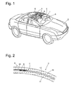
- Fig. 1 is a perspective view of a motor vehicle to which the present invention is applied.
- the vehicle has a windshield 1, which extends from the rear edge of a hood 2 up to a roof bow 3, the right and left B-pillars 4 of the body connects approximately at the level of the backrests of the driver and passenger seats.
- the disk 1 is divided along a boundary line 7 into a front oblique section 5 and an approximately horizontal roof section 6.
- the horizontal hatch section 6 transparently hatched in the figure is made opaque in practice to conceal metal wires 8 projecting from an edge of the Slice 1 forth to a rear mirror holder 9, which is mounted at the level of the boundary line 7 on the inside of the disc 1.
- only two wires 8 are shown extending from one of the A-pillars to the rear mirror holder 9 extend, but the wires could be performed in different numbers and from different sides to the rear mirror holder 9.
- Fig. 2 shows a section through the windscreen 1 in a vehicle longitudinal direction approximately centrally through the steering wheel extending vertical plane. It can be seen the structure of the glass sheet 1 of an outer glass layer 10 and an inner glass layer 11 and an intermediate flexible polymer layer 12th
- the roof section 6 is made opaque by a pigment layer 13, which is screen-printed on the inside of the outer glass layer 10.
- the pigment layer 13 conceals the metallic wires 8 running directly below it in the polymer layer 12.
- the wires 8 are here shown with a flattened cross-section in order to realize a line cross-section, despite the small distance between the glass layers 10, 11, which is necessary for the power requirement of the mirror holder 9 mounted electrical consumer is sufficient.
- a second pigment layer congruent with the layer 13 or even a strip-shaped layer can be attached to the surface of the glass layer 11 facing the polymer layer 12.
- FIG. 3 shows a second section through the pane 1 in a plane parallel to the sectional plane of FIG. 2 and passing through the mirror support 9.
- the mirror carrier 9, which is shown only partially, is hollow and has an annular flange 14 glued against the free surface of the inner glass layer 11, in which area the glass layer 11 is surrounded by the flange 14 a through hole 15, in which the polymer layer 12 and extending in her conductor wires 8 are exposed.
- Around the passage opening 15 around the contact area 16 are attached to the glass layer 11, for example in the form of glued to the glass layer 11, superficially metallized circuit boards. Bonding wires 17 extend between each of the conductors 8 and the contact pad 16 associated therewith. In order to contact an electrical consumer mounted on the mirror carrier, it is sufficient to solder connection wires of this consumer to the contact pads 16.
- the contact fields could also be equipped with connectors in the corresponding plug contacts of the consumer can be inserted.
- control electrodes of an electrochromic rearview mirror into consideration, which allow to adjust the tint of the rearview mirror to protect the driver of the vehicle from dazzling by the rear traffic. Since the power consumption of such an electrochromic mirror is low, instead of the wires 8, thin layers which are applied to the inner surfaces of the glass layers 10, 11 could be used for its power supply.
- Another possible consumer is an electric motor for tilting the rearview mirror, which is actuated, for example, by a remote control unit to set a predetermined orientation of the rearview mirror when a user logs on to the control unit as the driver of the vehicle who has previously set this mirror position as his preferred position programmed into the control unit.
- Another consumer contemplated for mounting to the mirror support 9 is an infrared sensor or other type of sensor suitable for detecting persons in the passenger compartment, which allows the intrusion of an unauthorized person into the passenger compartment and an alarm system trigger.
- an interior lighting can be integrated into the mirror holder as desired or arranged in the vicinity thereof and be supplied via the covered by the mirror holder through hole 15 with electrical power.
- a rain sensor 18 is shown schematically as an example of a consumer. This is glued to the disc 1 within the hollow mirror carrier 9 and comprises z.
- a light source such as a light emitting diode, which feeds light into the disc at a large angle of incidence, and a photodetector, which detects the presence of moisture-dependent intensity of the reflected light on the outside of the disc 1.
- FIGS. 2 and 3 each show only two electrical conductors 8, it is obvious that a larger number of conductors 8 can be provided if the number and / or complexity of the various consumers connected via the through-opening 15 necessitate this. Of course, several consumers can also be associated with individual through openings.
Abstract
Description
- Die vorliegende Erfindung betrifft eine Verbundglasscheibe wie etwa eine Front- oder Heckscheibe für ein Kraftfahrzeug sowie ein Kraftfahrzeug, das mit einer solchen Scheibe ausgestattet ist.
- Mit elektrischen Leitern versehene Verbundglasscheiben sind insbesondere als beheizbare Heckscheiben für Kraftfahrzeuge allgemein bekannt und verbreitet. Meist sind die Heizleiter derartiger Scheiben an der Innenseite der Scheiben angebracht.
- Aus
DE 100 18 276 A1 ist eine Verbundscheibe bekannt, bei der elektrisch leitfähige Drähte in eine thermoplastische Klebeschicht eingebettet sind, durch die zwei Glasschichten der Verbundscheibe miteinander verbunden sind. Die Drähte können als Scheibenheizung oder als eine Antenne dienen. Anschlüsse der Drähte sind an den Seitenrändern der Verbundscheibe, zwischen den zwei Glasschichten, herausgeführt. - Elektrische Verbraucher, die im Kopfbereich der Fahrgastzelle eines Kraftfahrzeugs montiert sein können, wie etwa eine Innenraumbeleuchtung, sind im Allgemeinen am Fahrzeugdach montiert, da es keine Schwierigkeiten bereitet, elektrische Versorgungskabel für diese Verbraucher zwischen der Außenhaut und einer Innenverkleidung des Dachs zu verlegen. Bei Kraftfahrzeugkarosserien, bei denen sich eine Windschutzscheibe oder Heckscheibe bis in den Dachbereich der Fahrgastzelle erstreckt, wie etwa in
DE 102 45 245 A1 undDE 198 52 184 A1 beschrieben, ist die Montage derartiger Verbraucher schwierig, da es nicht möglich ist, die Versorgungsleitungen eines solchen Verbrauchers auf ihrer ganzen Länge verdeckt zu führen. Zwar ist bei der Kraftfahrzeugkarosserie gemäßDE 198 52 184 A1 zwischen den verlängerten Front- und Heckscheiben noch ein schmaler die B-Säulen verbindender Spriegel zu erkennen, doch ist dieser kein günstiger Ort, um z. B. eine Innenraumbeleuchtung zu montieren, da es von dort aus nur schwerlich möglich ist, eine Landkarte, die ein Fahrer oder Beifahrer auf dem Schoß hält, vollständig zu beleuchten. - Aufgabe der vorliegenden Erfindung ist daher, eine Verbundglasscheibe für ein Kraftfahrzeug zu schaffen, die die Beschränkungen herkömmlicher Verbundglasscheiben, was die Anbringung elektrischer Verbraucher in der Fahrgastzelle angeht, überwindet.
- Die Aufgabe wird erfindungsgemäß dadurch gelöst, dass bei einer Verbundglasscheibe für ein Kraftfahrzeug mit wenigstens zwei Glasschichten und einer zwischen den Glasschichten angeordneten wenigstens in Teilbereichen elektrisch leitfähigen Zwischenschicht eine der Glasschichten eine Durchgangsöffnung aufweist, durch die wenigstens einer der Teilbereiche kontaktierbar ist, so dass es möglich ist, einen in der Nähe der Durchgangsöffnung angebrachten Verbraucher durch die Durchgangsöffnung hindurch mit Strom zu versorgen.
- Bei den elektrisch leitfähigen Teilbereichen der Zwischenschicht handelt es sich vorzugsweise um metallische Drähte, die in eine Polymerschicht als Zwischenschicht eingebettet sind. Je nach Leistungsaufnahme des Verbrauchers kommen eventuell auch andere Typen von leitfähigen Teilbereichen in Betracht, wie etwa eine aufgedampfte dünne Schicht aus Metall oder einem transparenten elektrisch leitfähigen Material, ein beispielsweise im Siebdruck strukturiert aufgetragenes, durch Zusatz von Metallpulver elektrisch leitfähig gemachtes Polymermaterial, etc.
- Um die elektrisch leitfähigen Teilbereiche, sofern sie nicht transparent sind, zu kaschieren, kann die Verbundglasscheibe lokal opak gemacht sein, und die leitfähigen Teilbereiche erstrecken sich zumindest überwiegend in dem opaken Bereich der Scheibe.
- Wenn die Verbundglasscheibe eine Kraftfahrzeug-Frontscheibe ist, ist die Durchgangsöffnung vorzugsweise in einem in Einbaulage der Scheibe oberen mittleren Bereich derselben angeordnet. Eine solche Platzierung ist beispielsweise gut geeignet für die Stromversorgung einer Innenraumbeleuchtung, eines elektrochromen Rückspiegels, von Stellmotoren eines motorisiert verstellbaren Rückspiegels, etc.
- Vorzugsweise sind benachbart zu der Durchgangsöffnung Kontaktfelder an einer Außenseite der durchbrochenen Glasschicht angeordnet und mit einem der Teilbereiche über ein durch die Durchgangsöffnung geführten Leiter kontaktiert. Diese Kontaktfelder erleichtern die elektrische Kontaktierung eines Verbrauchers an der Scheibe.
- Vorzugsweise ist das Gehäuse eines solchen Verbrauchers die Durchgangsöffnung überdeckend an der durchbrochenen Glasschicht angebracht, so dass zum einen die Öffnung für einen Benutzer unsichtbar bleibt und zum anderen die Zwischenschicht und ihre leitfähigen Bereiche vor Beschädigung geschützt sind.
- Weitere Merkmale der Erfindung ergeben sich aus der nachfolgenden Beschreibung von Ausführungsbeispielen unter Bezugnahme auf die beigefügten Figuren.
Es zeigen: - Fig. 1
- eine perspektivische Ansicht eines Kraftfahrzeugs, das mit einer erfindungsgemäßen Scheibe ausgestattet ist,
- Fig. 2
- einen ersten Teilschnitt durch die Verbundglasscheibe; und
- Fig. 3
- einen zweiten Teilschnitt durch die Verbundglasscheibe.
- Fig. 1 ist eine perspektivische Ansicht eines Kraftfahrzeugs, an dem die vorliegende Erfindung verwirklicht ist. Das Fahrzeug hat eine Frontscheibe 1, die sich von der rückwärtigen Kante einer Motorhaube 2 aus bis zu einem Dachspriegel 3 erstreckt, der rechte und linke B-Säulen 4 der Karosserie etwa in Höhe der Rückenlehnen von Fahrer- und Beifahrersitz verbindet. Die Scheibe 1 ist entlang einer Grenzlinie 7 unterteilt in einen vorderen schrägen Abschnitt 5 und einen in etwa horizontalen Dachabschnitt 6. Der in der Figur transparent schraffierte horizontale Dachabschnitt 6 ist in der Praxis opak gemacht, um Metalldrähte 8 zu verbergen, die von einem Rand der Scheibe 1 her zu einem Rückspiegelhalter 9 verlaufen, der in Höhe der Grenzlinie 7 an der Innenseite der Scheibe 1 montiert ist. In der Fig. sind nur zwei Drähte 8 gezeigt, die sich von einer der A-Säulen her zum Rückspiegelhalter 9 erstrecken, doch könnten die Drähte auch in anderer Zahl und von verschiedenen Seiten her zum Rückspiegelhalter 9 geführt sein.
- Fig. 2 zeigt einen Schnitt durch die Frontscheibe 1 in einer in Fahrzeuglängsrichtung etwa mittig durch das Lenkrad verlaufenden vertikalen Ebene. Man erkennt den Aufbau der Glasscheibe 1 aus einer äußeren Glasschicht 10 und einer inneren Glasschicht 11 und einer dazwischen liegenden flexiblen Polymerschicht 12.
- Der Dachabschnitt 6 ist opak gemacht durch eine Pigmentschicht 13, die im Siebdruck auf die Innenseite der äußeren Glasschicht 10 aufgetragen ist. Die Pigmentschicht 13 verdeckt die unmittelbar unter ihr in der Polymerschicht 12 verlaufenden metallischen Drähte 8. Die Drähte 8 sind hier mit einem abgeflachten Querschnitt dargestellt, um trotz geringen Abstands zwischen den Glasschichten 10, 11 einen Leitungsquerschnitt zu realisieren, der für den Leistungsbedarf eines am Spiegelhalter 9 angebrachten elektrischen Verbrauchers ausreicht.
- Um die Leiter 8 auch vom Inneren der Fahrgastzelle her unsichtbar zu machen, kann eine zweite, mit der Schicht 13 kongruente Pigmentschicht oder auch lediglich eine streifenförmige Schicht an der der Polymerschicht 12 zugewandten Oberfläche der Glasschicht 11 angebracht sein.
- Fig. 3 zeigt einen zweiten Schnitt durch die Scheibe 1 in einer zur Schnittebene der Fig. 2 parallelen, durch den Spiegelträger 9 verlaufenden Ebene. Der nur teilweise dargestellte Spiegelträger 9 ist hohl und hat einen ringförmigen, gegen die freie Oberfläche der inneren Glasschicht 11 geklebten Flansch 14. In dem von dem Flansch 14 umgebenen Bereich der Glasschicht 11 befindet sich eine Durchgangsöffnung 15, in der die Polymerschicht 12 und die in ihr verlaufenden Leiterdrähte 8 freiliegen. Um die Durchgangsöffnung 15 herum sind an der Glasschicht 11 Kontaktfelder 16 angebracht, beispielsweise in Form von an die Glasschicht 11 angeklebten, oberflächlich metallisierten Leiterplatten. Bonddrähte 17 erstrecken sich zwischen jedem der Leiter 8 und dem ihm zugeordneten Kontaktfeld 16. Um einen an den Spiegelträgers montierten elektrischen Verbraucher zu kontaktieren, genügt es, Anschlussdrähte dieses Verbrauchers an die Kontaktfelder 16 anzulöten. Die Kontaktfelder könnten aber auch mit Steckverbindern bestückt sein, in die entsprechende Steckkontakte des Verbrauchers einschiebbar sind.
- Als an die Kontaktfelder 16 anzuschließende Verbraucher kommen z. B. Steuerelektroden eines elektrochromen Rückspiegels in Betracht, die es erlauben, die Tönung des Rückspiegels einzustellen, um den Fahrer des Fahrzeugs vor Blendung durch den rückwärtigen Verkehr zu schützen. Da die Leistungsaufnahme eines solchen elektrochromen Spiegels gering ist, kämen zu seiner Stromversorgung anstelle der Drähte 8 auch an den Innenflächen der Glasschichten 10, 11 aufgebrachte Dünnschichten in Betracht.
- Ein anderer möglicher Verbraucher ist ein Elektromotor zum Kippen des Rückspiegels, der beispielsweise von einer entfernten Steuereinheit betätigt wird, um eine vorgegebene Orientierung des Rückspiegels einzustellen, wenn sich ein Benutzer bei dem Steuergerät als Fahrer des Fahrzeugs anmeldet, der zuvor diese Spiegelstellung als seine bevorzugte Stellung in das Steuergerät einprogrammiert hat.
- Ein weiterer Verbraucher, der zur Montage an dem Spiegelträger 9 in Betracht kommt, ist ein Infrarotsensor oder ein anderer Typ von zum Erfassen von Personen in der Fahrgastzelle geeigneter Sensor, der es erlaubt, das Eindringen einer unbefugten Person in den Fahrgastraum zu erfassen und eine Alarmanlage auszulösen.
- Auch eine Innenraumbeleuchtung kann nach Wunsch in den Spiegelhalter integriert oder in dessen Nähe angeordnet und über die von dem Spiegelhalter verdeckte Durchgangsöffnung 15 mit elektrischen Strom versorgt sein.
- In Fig. 3 ist als Beispiel für einen Verbraucher schematisch ein Regensensor 18 dargestellt. Dieser ist innerhalb des hohlen Spiegelträgers 9 an die Scheibe 1 geklebt und umfasst z. B. eine Lichtquelle wie etwa eine Leuchtdiode, die Licht unter einem großen Einfallswinkel in die Scheibe einspeist, und einen Photodetektor, der die vom Vorhandensein von Feuchtigkeit abhängige Intensität des an der Außenseite der Scheibe 1 reflektierten Lichts erfasst.
- Während die Fig. 2 und 3 jeweils nur zwei elektrische Leiter 8 zeigen, liegt auf der Hand, dass eine größere Zahl von Leitern 8 vorgesehen werden kann, wenn Anzahl und/oder Komplexität der verschiedenen über die Durchgangsöffnung 15 angeschlossenen Verbraucher dies erfordern. Selbstverständlich können mehreren Verbrauchern auch jeweils einzelne Durchgangsöffnungen zugeordnet sein.
-
- Frontscheibe
- 1
- Motorhaube
- 2
- Dachspriegel
- 3
- B-Säule
- 4
- Schräger Abschnitt
- 5
- Dachabschnitt
- 6
- Grenzlinie
- 7
- Leiter
- 8
- Spiegelhalter
- 9
- Glasschicht
- 10, 11
- Polymerschicht
- 12
- Pigmentschicht
- 13
- Flansch
- 14
- Durchgangsöffnung
- 15
- Kontaktfeld
- 16
- Bonddraht
- 17
- Verbraucher
- 18
Claims (9)
- Verbundglasscheibe (1) für ein Kraftfahrzeug mit wenigstens zwei Glasschichten (10, 11) und einer zwischen den Glasschichten angeordneten wenigstens in Teilbereichen (8) elektrisch leitfähigen Zwischenschicht (12), dadurch gekennzeichnet, dass eine der Glasschichten eine Durchgangsöffnung (15) aufweist, durch die wenigstens einer der Teilbereiche (8) kontaktierbar ist.
- Verbundglasscheibe nach Anspruch 1, dadurch gekennzeichnet, dass die Teilbereiche Drähte sind, die in ein Polymermaterial der Zwischenschicht (12) eingebettet sind.
- Verbundglasscheibe nach Anspruch 1 oder 2, dadurch gekennzeichnet, dass sie lokal opak ist und die leitfähigen Teilbereiche (8) sich zumindest überwiegend in dem opaken Bereich (6) der Scheibe (1) erstrecken.
- Verbundglasscheibe nach einem der vorhergehenden Ansprüche, dass sie eine Kraftfahrzeug-Frontscheibe (1) ist und dass die Durchgangsöffnung (15) in einem oberen mittleren Bereich der Scheibe (1) angeordnet ist.
- Verbundglasscheibe nach einem der vorhergehenden Ansprüche, dadurch gekennzeichnet, dass benachbart zu der Durchgangsöffnung (15) Kontaktfelder (16) an einer Außenseite der durchbrochenen Glasschicht (11) angeordnet und mit einem der Teilbereiche (18) über einen durch die Durchgangsöffnung (15) geführten Leiter (17) kontaktiert sind.
- Verbundglasscheibe nach einem der vorhergehenden Ansprüche, dadurch gekennzeichnet, dass ein Gehäuse (9) eines elektrischen Verbrauchers (18) die Durchgangsöffnung (15) überdeckend an der durchbrochenen Glasschicht (11) angebracht ist.
- Verbundglasscheibe nach Anspruch 6, dadurch gekennzeichnet, dass der Verbraucher eine Fahrgastraumbeleuchtung, ein elektrochromatischer Spiegel, ein Personendetektor oder ein Regensensor (18) ist.
- Kraftfahrzeug, dadurch gekennzeichnet, dass es eine Verbundglasscheibe (1) nach einem der vorhergehenden Ansprüche aufweist.
- Kraftfahrzeug nach Anspruch 8, dadurch gekennzeichnet, dass die Verbundglasscheibe (1) sich bis über die Sitzfläche eines Sitzes in der Fahrgastzelle des Kraftfahrzeugs erstreckt.
Applications Claiming Priority (1)
| Application Number | Priority Date | Filing Date | Title |
|---|---|---|---|
| DE102005016087A DE102005016087A1 (de) | 2005-04-08 | 2005-04-08 | Kraftfahrzeug und Verbundglasscheibe dafür |
Publications (3)
| Publication Number | Publication Date |
|---|---|
| EP1710104A2 true EP1710104A2 (de) | 2006-10-11 |
| EP1710104A3 EP1710104A3 (de) | 2006-12-13 |
| EP1710104B1 EP1710104B1 (de) | 2009-11-04 |
Family
ID=36693225
Family Applications (1)
| Application Number | Title | Priority Date | Filing Date |
|---|---|---|---|
| EP06007291A Not-in-force EP1710104B1 (de) | 2005-04-08 | 2006-04-06 | Kraftfahrzeug und Verbundglasscheibe dafür |
Country Status (3)
| Country | Link |
|---|---|
| EP (1) | EP1710104B1 (de) |
| AT (1) | ATE447501T1 (de) |
| DE (2) | DE102005016087A1 (de) |
Cited By (7)
| Publication number | Priority date | Publication date | Assignee | Title |
|---|---|---|---|---|
| WO2009030476A1 (en) * | 2007-09-05 | 2009-03-12 | Saint-Gobain Glass France | Glass pane having a detector for electromagnetic radiation |
| WO2014057224A1 (fr) * | 2012-10-12 | 2014-04-17 | Saint-Gobain Glass France | Vitrage feuillete |
| WO2014057200A1 (fr) * | 2012-10-12 | 2014-04-17 | Saint-Gobain Glass France | Fabrication d'un vitrage feuillete muni d'un conducteur electrique |
| US9365161B2 (en) | 2014-06-19 | 2016-06-14 | Mario Arturo Mannheim Astete | Panoramic extended windshield with integrated non-moving blind |
| US20210100074A1 (en) * | 2017-05-19 | 2021-04-01 | Agc Glass Europe | Side laminated automotive glazing |
| US11207875B2 (en) | 2016-04-27 | 2021-12-28 | Saint-Gobain Glass France | Enamel printing process for a laminated glazing having functional layers |
| US11541650B2 (en) * | 2017-03-30 | 2023-01-03 | Agp America S.A. | Automotive laminate with embedded wire circuit |
Families Citing this family (1)
| Publication number | Priority date | Publication date | Assignee | Title |
|---|---|---|---|---|
| DE102021208566A1 (de) | 2021-08-06 | 2023-02-09 | Volkswagen Aktiengesellschaft | Fahrzeugdachmodul für ein Kraftfahrzeug |
Citations (3)
| Publication number | Priority date | Publication date | Assignee | Title |
|---|---|---|---|---|
| DE19852184A1 (de) | 1998-11-12 | 2000-05-25 | Sekurit Saint Gobain Deutsch | Sichtscheibe für ein Kraftfahrzeug mit einem Dachbereich |
| DE10018276A1 (de) | 2000-04-13 | 2001-10-25 | Saint Gobain Sekurit D Gmbh | Verbundscheibe |
| DE10245245A1 (de) | 2002-09-26 | 2004-04-01 | Adam Opel Ag | Front- und/oder Heckscheibe für ein Fahrzeug |
Family Cites Families (7)
| Publication number | Priority date | Publication date | Assignee | Title |
|---|---|---|---|---|
| DE2023823C3 (de) * | 1970-05-15 | 1979-09-13 | Saint-Gobain Industries, Neuilly- Sur-Seine (Frankreich) | Windschutzscheibenantenne für Kraftfahrzeuge |
| US4827198A (en) * | 1988-02-09 | 1989-05-02 | General Motors Corporation | Vehicle windshield and wiper with rain sensor |
| DE3937605C2 (de) * | 1989-11-11 | 1998-09-03 | Mannesmann Vdo Ag | Feuchtigkeitssensor |
| DE9016664U1 (de) * | 1990-12-08 | 1991-02-28 | Vegla Vereinigte Glaswerke Gmbh, 5100 Aachen, De | |
| US6094981A (en) * | 1998-09-25 | 2000-08-01 | Itt Automotive Electrical Systems, Inc. | Capacitive rain sensor for windshield |
| DE10010599B4 (de) * | 2000-03-03 | 2005-12-15 | Daimlerchrysler Ag | Fahrzeugscheibe |
| DE10241728B4 (de) * | 2002-09-10 | 2006-03-16 | Saint-Gobain Glass Deutschland Gmbh | Mehrschichtiges elektrisches beheizbares Flächenelement |
-
2005
- 2005-04-08 DE DE102005016087A patent/DE102005016087A1/de not_active Withdrawn
-
2006
- 2006-04-06 AT AT06007291T patent/ATE447501T1/de active
- 2006-04-06 EP EP06007291A patent/EP1710104B1/de not_active Not-in-force
- 2006-04-06 DE DE502006005276T patent/DE502006005276D1/de active Active
Patent Citations (3)
| Publication number | Priority date | Publication date | Assignee | Title |
|---|---|---|---|---|
| DE19852184A1 (de) | 1998-11-12 | 2000-05-25 | Sekurit Saint Gobain Deutsch | Sichtscheibe für ein Kraftfahrzeug mit einem Dachbereich |
| DE10018276A1 (de) | 2000-04-13 | 2001-10-25 | Saint Gobain Sekurit D Gmbh | Verbundscheibe |
| DE10245245A1 (de) | 2002-09-26 | 2004-04-01 | Adam Opel Ag | Front- und/oder Heckscheibe für ein Fahrzeug |
Cited By (19)
| Publication number | Priority date | Publication date | Assignee | Title |
|---|---|---|---|---|
| WO2009030476A1 (en) * | 2007-09-05 | 2009-03-12 | Saint-Gobain Glass France | Glass pane having a detector for electromagnetic radiation |
| US8421011B2 (en) | 2007-09-05 | 2013-04-16 | Saint-Gobain Glass France | Glass pane having a detector for electromagnetic radiation |
| CN106346913A (zh) * | 2012-10-12 | 2017-01-25 | 法国圣戈班玻璃厂 | 叠层式玻璃窗单元 |
| US11376820B2 (en) | 2012-10-12 | 2022-07-05 | Saint-Gobain Glass France | Manufacturing process for laminated glazing unit |
| FR2996802A1 (fr) * | 2012-10-12 | 2014-04-18 | Saint Gobain | Vitrage feuillete |
| FR2996803A1 (fr) * | 2012-10-12 | 2014-04-18 | Saint Gobain | Fabrication d'un vitrage feuillete muni d'un conducteur electrique |
| CN103874578A (zh) * | 2012-10-12 | 2014-06-18 | 法国圣戈班玻璃厂 | 叠层式玻璃窗单元 |
| WO2014057200A1 (fr) * | 2012-10-12 | 2014-04-17 | Saint-Gobain Glass France | Fabrication d'un vitrage feuillete muni d'un conducteur electrique |
| WO2014057224A1 (fr) * | 2012-10-12 | 2014-04-17 | Saint-Gobain Glass France | Vitrage feuillete |
| US9616649B2 (en) | 2012-10-12 | 2017-04-11 | Saint-Gobain Glass France | Manufacturing laminated glazing provided with an electrical conductor |
| EA028695B1 (ru) * | 2012-10-12 | 2017-12-29 | Сэн-Гобэн Гласс Франс | Изготовление многослойного остекления, снабженного электрическим проводником |
| EA029815B1 (ru) * | 2012-10-12 | 2018-05-31 | Сэн-Гобэн Гласс Франс | Многослойное остекление |
| US10118369B2 (en) | 2012-10-12 | 2018-11-06 | Saint-Gobain Glass France | Laminated glazing unit |
| EP3590708A1 (de) * | 2012-10-12 | 2020-01-08 | Saint-Gobain Glass France | Mehrschichtenglas |
| US9365161B2 (en) | 2014-06-19 | 2016-06-14 | Mario Arturo Mannheim Astete | Panoramic extended windshield with integrated non-moving blind |
| US11207875B2 (en) | 2016-04-27 | 2021-12-28 | Saint-Gobain Glass France | Enamel printing process for a laminated glazing having functional layers |
| US11541650B2 (en) * | 2017-03-30 | 2023-01-03 | Agp America S.A. | Automotive laminate with embedded wire circuit |
| US20210100074A1 (en) * | 2017-05-19 | 2021-04-01 | Agc Glass Europe | Side laminated automotive glazing |
| US11648751B2 (en) * | 2017-05-19 | 2023-05-16 | Agc Glass Europe | Side laminated automotive glazing |
Also Published As
| Publication number | Publication date |
|---|---|
| EP1710104B1 (de) | 2009-11-04 |
| ATE447501T1 (de) | 2009-11-15 |
| DE102005016087A1 (de) | 2006-10-12 |
| EP1710104A3 (de) | 2006-12-13 |
| DE502006005276D1 (de) | 2009-12-17 |
Similar Documents
| Publication | Publication Date | Title |
|---|---|---|
| EP1710104B1 (de) | Kraftfahrzeug und Verbundglasscheibe dafür | |
| EP3386748B1 (de) | Fahrzeug-verbundscheibe mit integriertem lichtsensor | |
| DE10329643B4 (de) | Verfahren zur Herstellung eines Deckels mit einer Glasscheibe und elektrischen Funktionselementen | |
| EP3426485B1 (de) | Beleuchtbare verbundscheibe | |
| DE19832228C2 (de) | Antennenscheibe für Kraftfahrzeuge | |
| EP3245083B1 (de) | Deckel eines fahrzeugdaches mit einer beleuchtungseinrichtung | |
| DE19723596C1 (de) | Lichtdurchlässiger Deckel für ein Fahrzeugdach | |
| WO2017077128A1 (de) | Elektrisch beheizbare verbundscheibe mit kapazitivem schaltbereich | |
| DE3730346A1 (de) | Glasscheibe fuer ein kraftfahrzeug | |
| DE19852184A1 (de) | Sichtscheibe für ein Kraftfahrzeug mit einem Dachbereich | |
| EP3941740A1 (de) | Fahrzeug-verbundscheibe mit einem heizbaren einlegeelement | |
| EP4065369A1 (de) | Verbundscheibe mit in thermoplastischer zwischenschicht eingelagertem funktionselement und entlüftungsstruktur | |
| EP1264719B1 (de) | Transparente Scheibe für ein Fahrzeugdach oder für ein Fahrzeugdachmodul | |
| EP1514731A2 (de) | Fahrzeugleuchte | |
| DE102005042960A1 (de) | Vorrichtung zur Übertragung elektrischer Signale und elektrischer Energie in einem Kraftfahrzeug | |
| DE102007040008A1 (de) | Fahrzeugdach mit einem durchsichtigen Bereich | |
| DE102018208804A1 (de) | Fahrzeug mit umgreifender Frontscheibe und elektrischer Komponente zwischen Vordersäule und Frontscheibe | |
| EP1312496B1 (de) | Dachsystem für ein Fahrzeug | |
| DE102006041929B4 (de) | Helm | |
| DE202020005428U1 (de) | Verbundscheibe mit elektrisch steuerbaren optischen Eigenschaften und Verbundscheibenanordnung | |
| DE102004055175A1 (de) | Kraftfahrzeug mit zumindest einer Antenne im Dachbereich | |
| DE19905098A1 (de) | Kraftfahrzeug mit Solargenerator | |
| DE60014259T2 (de) | Glasdach mit Einschlagschutz | |
| DE2017790A1 (de) | Geschichtete Windschutzscheibe mit eingebauter Antenne | |
| DE202021004033U1 (de) | Verbundscheibenanordnung mit Touch-Bedienelement zur Steuerung einer Funktion |
Legal Events
| Date | Code | Title | Description |
|---|---|---|---|
| PUAI | Public reference made under article 153(3) epc to a published international application that has entered the european phase |
Free format text: ORIGINAL CODE: 0009012 |
|
| AK | Designated contracting states |
Kind code of ref document: A2 Designated state(s): AT BE BG CH CY CZ DE DK EE ES FI FR GB GR HU IE IS IT LI LT LU LV MC NL PL PT RO SE SI SK TR |
|
| AX | Request for extension of the european patent |
Extension state: AL BA HR MK YU |
|
| PUAL | Search report despatched |
Free format text: ORIGINAL CODE: 0009013 |
|
| AK | Designated contracting states |
Kind code of ref document: A3 Designated state(s): AT BE BG CH CY CZ DE DK EE ES FI FR GB GR HU IE IS IT LI LT LU LV MC NL PL PT RO SE SI SK TR |
|
| AX | Request for extension of the european patent |
Extension state: AL BA HR MK YU |
|
| 17P | Request for examination filed |
Effective date: 20070312 |
|
| 17Q | First examination report despatched |
Effective date: 20070427 |
|
| AKX | Designation fees paid |
Designated state(s): AT BE BG CH CY CZ DE DK EE ES FI FR GB GR HU IE IS IT LI LT LU LV MC NL PL PT RO SE SI SK TR |
|
| GRAP | Despatch of communication of intention to grant a patent |
Free format text: ORIGINAL CODE: EPIDOSNIGR1 |
|
| GRAS | Grant fee paid |
Free format text: ORIGINAL CODE: EPIDOSNIGR3 |
|
| GRAA | (expected) grant |
Free format text: ORIGINAL CODE: 0009210 |
|
| AK | Designated contracting states |
Kind code of ref document: B1 Designated state(s): AT BE BG CH CY CZ DE DK EE ES FI FR GB GR HU IE IS IT LI LT LU LV MC NL PL PT RO SE SI SK TR |
|
| REG | Reference to a national code |
Ref country code: GB Ref legal event code: FG4D Free format text: NOT ENGLISH |
|
| REG | Reference to a national code |
Ref country code: CH Ref legal event code: EP |
|
| REG | Reference to a national code |
Ref country code: IE Ref legal event code: FG4D |
|
| REF | Corresponds to: |
Ref document number: 502006005276 Country of ref document: DE Date of ref document: 20091217 Kind code of ref document: P |
|
| NLV1 | Nl: lapsed or annulled due to failure to fulfill the requirements of art. 29p and 29m of the patents act | ||
| LTIE | Lt: invalidation of european patent or patent extension |
Effective date: 20091104 |
|
| PG25 | Lapsed in a contracting state [announced via postgrant information from national office to epo] |
Ref country code: SE Free format text: LAPSE BECAUSE OF FAILURE TO SUBMIT A TRANSLATION OF THE DESCRIPTION OR TO PAY THE FEE WITHIN THE PRESCRIBED TIME-LIMIT Effective date: 20091104 Ref country code: ES Free format text: LAPSE BECAUSE OF FAILURE TO SUBMIT A TRANSLATION OF THE DESCRIPTION OR TO PAY THE FEE WITHIN THE PRESCRIBED TIME-LIMIT Effective date: 20100215 Ref country code: PT Free format text: LAPSE BECAUSE OF FAILURE TO SUBMIT A TRANSLATION OF THE DESCRIPTION OR TO PAY THE FEE WITHIN THE PRESCRIBED TIME-LIMIT Effective date: 20100304 Ref country code: FI Free format text: LAPSE BECAUSE OF FAILURE TO SUBMIT A TRANSLATION OF THE DESCRIPTION OR TO PAY THE FEE WITHIN THE PRESCRIBED TIME-LIMIT Effective date: 20091104 Ref country code: IS Free format text: LAPSE BECAUSE OF FAILURE TO SUBMIT A TRANSLATION OF THE DESCRIPTION OR TO PAY THE FEE WITHIN THE PRESCRIBED TIME-LIMIT Effective date: 20100304 Ref country code: LT Free format text: LAPSE BECAUSE OF FAILURE TO SUBMIT A TRANSLATION OF THE DESCRIPTION OR TO PAY THE FEE WITHIN THE PRESCRIBED TIME-LIMIT Effective date: 20091104 |
|
| REG | Reference to a national code |
Ref country code: IE Ref legal event code: FD4D |
|
| PG25 | Lapsed in a contracting state [announced via postgrant information from national office to epo] |
Ref country code: LV Free format text: LAPSE BECAUSE OF FAILURE TO SUBMIT A TRANSLATION OF THE DESCRIPTION OR TO PAY THE FEE WITHIN THE PRESCRIBED TIME-LIMIT Effective date: 20091104 Ref country code: CY Free format text: LAPSE BECAUSE OF FAILURE TO SUBMIT A TRANSLATION OF THE DESCRIPTION OR TO PAY THE FEE WITHIN THE PRESCRIBED TIME-LIMIT Effective date: 20091104 Ref country code: PL Free format text: LAPSE BECAUSE OF FAILURE TO SUBMIT A TRANSLATION OF THE DESCRIPTION OR TO PAY THE FEE WITHIN THE PRESCRIBED TIME-LIMIT Effective date: 20091104 Ref country code: SI Free format text: LAPSE BECAUSE OF FAILURE TO SUBMIT A TRANSLATION OF THE DESCRIPTION OR TO PAY THE FEE WITHIN THE PRESCRIBED TIME-LIMIT Effective date: 20091104 |
|
| PG25 | Lapsed in a contracting state [announced via postgrant information from national office to epo] |
Ref country code: BG Free format text: LAPSE BECAUSE OF FAILURE TO SUBMIT A TRANSLATION OF THE DESCRIPTION OR TO PAY THE FEE WITHIN THE PRESCRIBED TIME-LIMIT Effective date: 20100204 Ref country code: IE Free format text: LAPSE BECAUSE OF FAILURE TO SUBMIT A TRANSLATION OF THE DESCRIPTION OR TO PAY THE FEE WITHIN THE PRESCRIBED TIME-LIMIT Effective date: 20091104 Ref country code: DK Free format text: LAPSE BECAUSE OF FAILURE TO SUBMIT A TRANSLATION OF THE DESCRIPTION OR TO PAY THE FEE WITHIN THE PRESCRIBED TIME-LIMIT Effective date: 20091104 Ref country code: EE Free format text: LAPSE BECAUSE OF FAILURE TO SUBMIT A TRANSLATION OF THE DESCRIPTION OR TO PAY THE FEE WITHIN THE PRESCRIBED TIME-LIMIT Effective date: 20091104 Ref country code: RO Free format text: LAPSE BECAUSE OF FAILURE TO SUBMIT A TRANSLATION OF THE DESCRIPTION OR TO PAY THE FEE WITHIN THE PRESCRIBED TIME-LIMIT Effective date: 20091104 |
|
| PG25 | Lapsed in a contracting state [announced via postgrant information from national office to epo] |
Ref country code: CZ Free format text: LAPSE BECAUSE OF FAILURE TO SUBMIT A TRANSLATION OF THE DESCRIPTION OR TO PAY THE FEE WITHIN THE PRESCRIBED TIME-LIMIT Effective date: 20091104 Ref country code: SK Free format text: LAPSE BECAUSE OF FAILURE TO SUBMIT A TRANSLATION OF THE DESCRIPTION OR TO PAY THE FEE WITHIN THE PRESCRIBED TIME-LIMIT Effective date: 20091104 |
|
| PLBE | No opposition filed within time limit |
Free format text: ORIGINAL CODE: 0009261 |
|
| STAA | Information on the status of an ep patent application or granted ep patent |
Free format text: STATUS: NO OPPOSITION FILED WITHIN TIME LIMIT |
|
| 26N | No opposition filed |
Effective date: 20100805 |
|
| PG25 | Lapsed in a contracting state [announced via postgrant information from national office to epo] |
Ref country code: GR Free format text: LAPSE BECAUSE OF FAILURE TO SUBMIT A TRANSLATION OF THE DESCRIPTION OR TO PAY THE FEE WITHIN THE PRESCRIBED TIME-LIMIT Effective date: 20100205 |
|
| BERE | Be: lapsed |
Owner name: GM GLOBAL TECHNOLOGY OPERATIONS, INC. Effective date: 20100430 |
|
| PG25 | Lapsed in a contracting state [announced via postgrant information from national office to epo] |
Ref country code: MC Free format text: LAPSE BECAUSE OF NON-PAYMENT OF DUE FEES Effective date: 20100430 |
|
| REG | Reference to a national code |
Ref country code: CH Ref legal event code: PL |
|
| PG25 | Lapsed in a contracting state [announced via postgrant information from national office to epo] |
Ref country code: LI Free format text: LAPSE BECAUSE OF NON-PAYMENT OF DUE FEES Effective date: 20100430 Ref country code: CH Free format text: LAPSE BECAUSE OF NON-PAYMENT OF DUE FEES Effective date: 20100430 |
|
| PG25 | Lapsed in a contracting state [announced via postgrant information from national office to epo] |
Ref country code: BE Free format text: LAPSE BECAUSE OF NON-PAYMENT OF DUE FEES Effective date: 20100430 Ref country code: IT Free format text: LAPSE BECAUSE OF FAILURE TO SUBMIT A TRANSLATION OF THE DESCRIPTION OR TO PAY THE FEE WITHIN THE PRESCRIBED TIME-LIMIT Effective date: 20091104 |
|
| REG | Reference to a national code |
Ref country code: DE Ref legal event code: R081 Ref document number: 502006005276 Country of ref document: DE Owner name: GM GLOBAL TECHNOLOGY OPERATIONS LLC (N. D. GES, US Free format text: FORMER OWNER: GM GLOBAL TECHNOLOGY OPERATIONS, INC., DETROIT, US Effective date: 20110323 |
|
| PGFP | Annual fee paid to national office [announced via postgrant information from national office to epo] |
Ref country code: DE Payment date: 20120419 Year of fee payment: 7 |
|
| PG25 | Lapsed in a contracting state [announced via postgrant information from national office to epo] |
Ref country code: HU Free format text: LAPSE BECAUSE OF FAILURE TO SUBMIT A TRANSLATION OF THE DESCRIPTION OR TO PAY THE FEE WITHIN THE PRESCRIBED TIME-LIMIT Effective date: 20100505 Ref country code: LU Free format text: LAPSE BECAUSE OF NON-PAYMENT OF DUE FEES Effective date: 20100406 Ref country code: NL Free format text: LAPSE BECAUSE OF FAILURE TO SUBMIT A TRANSLATION OF THE DESCRIPTION OR TO PAY THE FEE WITHIN THE PRESCRIBED TIME-LIMIT Effective date: 20091104 |
|
| PG25 | Lapsed in a contracting state [announced via postgrant information from national office to epo] |
Ref country code: TR Free format text: LAPSE BECAUSE OF FAILURE TO SUBMIT A TRANSLATION OF THE DESCRIPTION OR TO PAY THE FEE WITHIN THE PRESCRIBED TIME-LIMIT Effective date: 20091104 |
|
| REG | Reference to a national code |
Ref country code: AT Ref legal event code: MM01 Ref document number: 447501 Country of ref document: AT Kind code of ref document: T Effective date: 20110406 |
|
| PG25 | Lapsed in a contracting state [announced via postgrant information from national office to epo] |
Ref country code: AT Free format text: LAPSE BECAUSE OF NON-PAYMENT OF DUE FEES Effective date: 20110406 |
|
| PG25 | Lapsed in a contracting state [announced via postgrant information from national office to epo] |
Ref country code: DE Free format text: LAPSE BECAUSE OF NON-PAYMENT OF DUE FEES Effective date: 20131101 |
|
| REG | Reference to a national code |
Ref country code: DE Ref legal event code: R119 Ref document number: 502006005276 Country of ref document: DE Effective date: 20131101 |
|
| REG | Reference to a national code |
Ref country code: FR Ref legal event code: PLFP Year of fee payment: 11 |
|
| PGFP | Annual fee paid to national office [announced via postgrant information from national office to epo] |
Ref country code: FR Payment date: 20160309 Year of fee payment: 11 |
|
| PGFP | Annual fee paid to national office [announced via postgrant information from national office to epo] |
Ref country code: GB Payment date: 20160406 Year of fee payment: 11 |
|
| GBPC | Gb: european patent ceased through non-payment of renewal fee |
Effective date: 20170406 |
|
| REG | Reference to a national code |
Ref country code: FR Ref legal event code: ST Effective date: 20171229 |
|
| PG25 | Lapsed in a contracting state [announced via postgrant information from national office to epo] |
Ref country code: FR Free format text: LAPSE BECAUSE OF NON-PAYMENT OF DUE FEES Effective date: 20170502 |
|
| PG25 | Lapsed in a contracting state [announced via postgrant information from national office to epo] |
Ref country code: GB Free format text: LAPSE BECAUSE OF NON-PAYMENT OF DUE FEES Effective date: 20170406 |