EP1710037B1 - Vorrichtung und verfahren zum kurzschluss-lichtbogenschweissen - Google Patents
Vorrichtung und verfahren zum kurzschluss-lichtbogenschweissen Download PDFInfo
- Publication number
- EP1710037B1 EP1710037B1 EP05075814.3A EP05075814A EP1710037B1 EP 1710037 B1 EP1710037 B1 EP 1710037B1 EP 05075814 A EP05075814 A EP 05075814A EP 1710037 B1 EP1710037 B1 EP 1710037B1
- Authority
- EP
- European Patent Office
- Prior art keywords
- welding
- current
- short
- vip
- weld puddle
- Prior art date
- Legal status (The legal status is an assumption and is not a legal conclusion. Google has not performed a legal analysis and makes no representation as to the accuracy of the status listed.)
- Active
Links
- 238000003466 welding Methods 0.000 title claims description 156
- 238000000034 method Methods 0.000 title claims description 56
- 230000000737 periodic effect Effects 0.000 claims description 55
- 229910001338 liquidmetal Inorganic materials 0.000 claims description 20
- 239000002184 metal Substances 0.000 claims description 18
- 230000003247 decreasing effect Effects 0.000 claims description 11
- 238000000151 deposition Methods 0.000 claims description 10
- 230000004044 response Effects 0.000 claims description 5
- 238000004590 computer program Methods 0.000 claims description 4
- 238000012545 processing Methods 0.000 claims description 4
- 238000004891 communication Methods 0.000 claims description 3
- 238000004519 manufacturing process Methods 0.000 claims description 3
- 230000008569 process Effects 0.000 description 12
- PUIYMUZLKQOUOZ-UHFFFAOYSA-N isoproturon Chemical compound CC(C)C1=CC=C(NC(=O)N(C)C)C=C1 PUIYMUZLKQOUOZ-UHFFFAOYSA-N 0.000 description 7
- 230000008602 contraction Effects 0.000 description 5
- 239000007789 gas Substances 0.000 description 5
- XKRFYHLGVUSROY-UHFFFAOYSA-N Argon Chemical compound [Ar] XKRFYHLGVUSROY-UHFFFAOYSA-N 0.000 description 4
- 230000007423 decrease Effects 0.000 description 3
- 238000010586 diagram Methods 0.000 description 3
- 239000000203 mixture Substances 0.000 description 3
- 229910052786 argon Inorganic materials 0.000 description 2
- 230000001419 dependent effect Effects 0.000 description 2
- 239000000463 material Substances 0.000 description 2
- 238000012216 screening Methods 0.000 description 2
- 239000011800 void material Substances 0.000 description 2
- 230000008901 benefit Effects 0.000 description 1
- 238000004364 calculation method Methods 0.000 description 1
- 238000010276 construction Methods 0.000 description 1
- 230000009474 immediate action Effects 0.000 description 1
- 238000005259 measurement Methods 0.000 description 1
- 238000002844 melting Methods 0.000 description 1
- 230000008018 melting Effects 0.000 description 1
- 238000012552 review Methods 0.000 description 1
- 238000012546 transfer Methods 0.000 description 1
- 230000007704 transition Effects 0.000 description 1
Images


Classifications
-
- B—PERFORMING OPERATIONS; TRANSPORTING
- B23—MACHINE TOOLS; METAL-WORKING NOT OTHERWISE PROVIDED FOR
- B23K—SOLDERING OR UNSOLDERING; WELDING; CLADDING OR PLATING BY SOLDERING OR WELDING; CUTTING BY APPLYING HEAT LOCALLY, e.g. FLAME CUTTING; WORKING BY LASER BEAM
- B23K9/00—Arc welding or cutting
- B23K9/09—Arrangements or circuits for arc welding with pulsed current or voltage
- B23K9/091—Arrangements or circuits for arc welding with pulsed current or voltage characterised by the circuits
- B23K9/092—Arrangements or circuits for arc welding with pulsed current or voltage characterised by the circuits characterised by the shape of the pulses produced
Definitions
- the invention pertains to an apparatus and a method for welding by depositing drops of molten metal at the end of a welding electrode into a weld puddle, in particular for short-circuit arc welding.
- a molten tip of a welding wire short-circuits with the weld puddle and the tip is "burned-off" from the welding wire due to a pinch-effect caused by the short-circuit current. After the burn-off, an arc is formed between the welding wire and the weld puddle. The arc will cause the tip of the welding wire to meld and the molten tip of the welding wire is moved towards the weld puddle. The molten tip of a welding wire short-circuits with the weld puddle and the process repeats itself.
- GMAW Gas Metal Arc Welding
- a disadvantage of short-circuit welding is the occurrence of spatter. Spatter occurs during the burning-off of the welding wire. Spatter particularly occurs when too much power is supplied when the short-circuit is clearing, in particular during the transition from a short-circuit state to an arc state.
- the arc voltage or its first derivative may be compared to a threshold value for the detecting and predicting of the clearing of the short-circuit.
- a threshold value for the detecting and predicting of the clearing of the short-circuit.
- the United States Patent 6,087,626 discloses the use of a feedback signal for controlling the welding process, wherein the feedback signal is a real-time signal indicative of the heat input to each drop at the tip of the welding wire.
- the method also predicts when the short-circuit is about to clear in response to the power delivered.
- such more complicated methods for predicting the clearing of the short-circuit result, among other things, in a relatively slow welding process.
- a first object of this invention is to provide an apparatus and a method for welding providing an efficient way for reducing the occurrence of spatter.
- a second object of the invention is to provide an apparatus and method for welding without a means for predicting the clearance of the short-circuit and/or for reducing the power or current just before the short-circuit clears.
- a third object of the invention is to provide an apparatus and method in which the welding conditions are less critical and/or can be readily set.
- a fourth object of the invention is to provide an apparatus and method for high-speed welding.
- a first aspect of the invention provides a method of welding by depositing drops of molten metal at the end of a welding electrode into a weld puddle for short-circuit arc welding, comprising the steps of:
- the periodic signal Due to the periodic signal superimposed on the current, and in particular on the short-circuit current, the current is repeatedly increased and decreased; at each cycle of the periodic signal, the current decreases after it has reached its maximum value. Due to the superimposed periodic signal the occurrence of spatter is at least reduced.
- the periodic signal may comprise an alternating signal.
- the method of the inventions does not require the predictions of the clearance of the short-circuit and for reducing the power or current just before the short-circuit clears. Thus the complicated predicting methods are no longer necessary, thus allowing welding at high speeds.
- pulses in arc welding is for example disclosed in EP 0 369 367 , EP 1 232 825 , US 5,726,419 , Patent abstracts of Japan vol. 007, no. 153 and Patent abstracts of Japan vol.011, no. 281.
- pulsed arc welding which is a method where the current waveform of the whole welding cycle is implemented as a series of current pulses. In such pulse welding, the widths of the current pulses control the magnitude or height of the waveform.
- the current and/or the frequency of the periodic signal is adjusted, preferably continuously varied, at least until after the short-circuit has cleared.
- the contracting force is also periodically modulated and the column of liquid metal between the welding electrode and the weld puddle periodically contracts.
- a natural frequency of the liquid metal column can be changed.
- the contraction of the liquid metal column may be greatly enhanced when the frequency of the periodic signal is near to, or is substantially equal to a natural frequency of the liquid metal column.
- the enhanced pinch-effect yields a rapid clearing of the short-circuit substantially without spatter.
- the natural frequency of the liquid metal column and/or the frequency of the periodic signal are continuously varied. As soon as the frequency of the periodic signal is near to, or is substantially equal to a natural frequency of the liquid metal column, the pinch-effect is enhanced, yielding a rapid clearing of the short-circuit substantially without spatter. In view of this variation of the current and/or the frequency of the periodic signal, it is not necessary in this embodiment to determine a natural frequency of the liquid metal column.
- the frequency of the periodic signal is tuned to a value substantially equal to a resonance frequency of a liquid metal column between the welding electrode and the weld puddle, and/or a resonance frequency of the liquid metal column between the welding electrode and the weld puddle is tuned to a value substantially equal to the frequency of the periodic signal.
- the periodic contraction of the liquid metal column may be out of phase with the periodic signal. That is, the contraction will be at its greatest after the current has reached its maximum value and is already decreasing.
- the welding conditions may be chosen such that the contraction is in anti-phase with the periodic signal. That is, the contraction will be at its greatest when the current substantially reaches its minimum value. In this case the short-circuit will clear when the power supplied to the short-circuit is substantially at his lowest.
- the welding process according to the invention can be controlled.
- the simple comparing the feedback signal to a reference value allows a rapid control of a high speed welding process.
- the step of increasing the current with the periodic signal superimposed thereon after the feedback signal has reached the first reference value V1 comprises the stages of:
- the current is relatively rapidly increased to the second value I2.
- the holding of the current at the second value I2 may be very short. The rapid increase is used to save time.
- the current with the superimposed periodic signal thereon is increased relatively slowly towards the third value I3, which increase changes the natural frequencies of the liquid metal column, allows a natural frequency to tune to a value substantially equal to the frequency of the periodic signal.
- the increasing of the current with the periodic signal superimposed thereon comprises the increasing of the average value of the current and/or the increasing of the amplitude of the periodic signal.
- the method according to the invention further comprises the steps of:
- the weld puddle Due to the low current during the fourth period of time T4, the weld puddle is allowed to calm down after the rapid clearing of the short-circuit, which may further prevent the production of spatter.
- the plasma boost By subsequently increasing and holding the current to the fifth value I5, sometimes called the "plasma boost", energy can be provide for melting the tip of the welding electrode.
- the energy input of the plasma boost determines, among other things, the amount of melted metal.
- the current is preferably decreased to the sixth value I6 before the welding electrode and the weld puddle short-circuit again.
- This decreased current I6 enables that the power supplied at the moment of short-circuiting is low, thus substantially preventing the occurrence of spatter when the welding electrode and the weld puddle short-circuit.
- the invention provides a method for producing a line shaped weld, preferably a continuous line shaped weld, by cyclical repeating the steps of the method of welding according to the invention and/or embodiments thereof as described above.
- the welding electrode comprises a consumable welding wire.
- the welding wire is continuously fed towards the weld puddle.
- the method comprises the step of feeding the welding wire towards the weld puddle at a speed equal to or in excess of 3.5 meters per minute, preferable equal to or in excess of 6 meters per minute.
- the invention provides a welding apparatus for welding by depositing drops of molten metal at the end of a welding electrode into a weld puddle, in particular for short-circuit arc welding, comprising:
- the modulating means comprise a waveform generator coupled to the power source for superimposing a periodic signal, preferably a harmonic signal, having a frequency and an amplitude, on the output of the power source.
- the first controlling means is arranged for adjusting, preferably continuously varying, the current output and/or the frequency of the periodic signal, preferably at least during the depositing of the drops of molten metal into the weld puddle.
- the first controlling means comprises scanning means for scanning the current output and/or the frequency of the periodic signal over a preset range, preferably at least during the depositing of each drop of molten metal into the weld puddle.
- the welding apparatus comprises feedback means for providing a feedback signal proportional to a voltage across the welding electrode and the weld puddle, and second controlling means for controlling the current output and or the frequency of the periodic signal, in dependence to the feedback signal.
- the welding apparatus comprises a first comparator for determining when the feedback signal reaches a first reference value V1 corresponding to a short-circuit circuiting of the welding electrode and the weld puddle, and a second comparator for determining when the feedback signal reaches a second reference value V2 corresponding to a clearing of the short-circuit circuiting, wherein the second controlling means preferably are arranged for increasing the current through the welding electrode in response to a signal from the first comparator and for decreasing the current through the welding electrode in response to a signal from the second comparator.
- the welding electrode comprises a consumable welding wire
- the welding apparatus comprises a welding wire feeding means for feeding the welding wire towards the weld puddle.
- the welding wire feeding means are arranged for feeding the welding wire at a speed equal to or in excess of 3.5 meters per minute, preferable equal to or in excess of 6 meters per minute.
- the invention provides a welding apparatus for welding by depositing drops of molten metal at the end of a welding electrode into a weld puddle, in particular for short-circuit circuit arc welding, comprising:
- the invention provides a welding robot comprising a welding apparatus according to the invention and/or embodiments thereof as described above.
- the invention provides a computer program comprising code means adapted to perform all steps defined in the method of welding according to the invention and/or embodiments thereof as described above.
- the invention provides a computer program product comprising a computer readable medium having computer readable code embodied thereon, the program being adapted to perform all steps defined in the method of welding according to the invention and/or embodiments thereof as described above.
- the first phase 1 (Touch phase) follows after the drop of molten metal 11 at the end of the welding electrode 10 short-circuits with the weld puddle 20, that is when the measured voltage decreases below the first reference value V1. In this first phase 1 the current is lowered to a value I1. The length of the first phase 1 is determined by a preset time-period T1.
- the drop of molten metal 11 joins with the weld puddle 20, and the current is increased to a value I2.
- the length of the second phase 2 is determined by a preset time-period T2.
- the periodic signal 30 is superimposed onto the current and the current with the periodic signal superimposed thereon is increased towards a value I3. This increase is continued until after the measured voltage increases above the second reference value V2, indicating that the short-circuit has cleared and an arc 40 is present between the end of the welding electrode 10 and the weld puddle 20.
- the current is lowered to a value I4, and the weld puddle 20 is allowed to settle.
- the length of the fourth phase 4 is determined by a preset time-period T3.
- the current is raised to a value I5 during a preset time-period T4, in order to provide a new drop of liquid metal 11 at the end of the welding electrode 10.
- the current is lowered in the sixth phase 6 (Pre-short-circuit phase) to a value I6.
- the sixth phase 6 is continued until after the measured voltage decreases below the first reference value V1, indicating that the drop of molten metal 11 at the end of the welding electrode 10 short-circuits with the weld puddle 20.
- the current is reduced after the clearing of the short-circuit, and the arc 40 is ignited.
- measurements and calculations are performed at least during the Join phase 2 and/of the Release phase 3 to predict when the short-circuit is about to clear, in order to reduce the power or current just before the short-circuit clears.
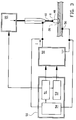
- FIG 3 shows an exemplary embodiment of a welding apparatus 50 of the invention, wherein the apparatus 50 is provided with controlling device 51 for controlling the welding apparatus 50.
- the controlling device 51 comprise a data processing system, such as for example a PLC (Programmable Logic Control) or a microprocessor, comprising means adapted to control each of the phases illustrated in figure 1 and described above.
- the data processing system is coupled the various components of the welding apparatus 50 for producing the current output is illustrated in figure 1 .
- This current output may be generated by starting the exemplary procedure "periodicly_called_function" below at regular time-intervals.
- the parameter vip_Iprofile is outputted to a digital/analog converter and supplied to the welding inverter 52 for controlling the current output of said inverter 52.
- To every phase belongs an adjustable end-current vip_Iend and an adjustable slope vip_dI for increasing the current output towards the end-current vip_Iend.
- the controlling device 51 also activates the waveform generator 53 for superimposing the periodic signal 30 onto the current output of the inverter 52.
- the controlling device 51 may also control one or more of the frequency, the amplitude and the waveform of the periodic signal 30.
- a background current may be added to the current output. This background current may be used to adjust the average measured welding voltage to a preferred value.
- the welding apparatus further comprises a voltmeter 54 to measure the welding voltage.
- the voltmeter 54 supplies a feedback signal proportional to the welding voltage, to the controlling device 51.
- the parameter vip_measured_voltage comprises this feedback signal. During the above described procedure, the vip_measured_voltage is compared with preset reference voltages V_short_circuit and V_free.
- the Touch phase 1 starts after the measured welding voltage vip_measured_voltage becomes smaller than a preset reference voltage V1, represented by the parameter V_short_circuit. During the Touch phase the current is lowered to a value I1, represented by the parameter TOUCH_Iend, using a preset slope TOUCH_dI. The Touch phase 1 is subsequently followed by the Join phase 2 after expiry of a preset time-period T1, represented by the parameter TOUCH_tlim.
- the current is raised to a value I2, represented by the parameter JOIN_Iend, using a preset slope JOIN_dI.
- the Join phase 2 is normally followed by the Release phase 3 after expiry of a preset time-period T2, represented by the parameter JOIN_tlim.
- the measured voltage represented by the parameter vip_measured_voltage
- V2 the preset reference voltage
- the procedure will immediately commence with the Settle phase 4, skipping the Release phase 3.
- the current is raised towards a value I3, represented by the parameter RELEASE_Iend, using a preset slope RELEASE_dI. Furthermore, during this phase, the periodic signal 30 is superimposed onto the current output.
- the Release phase 3 will only end when the measured voltage represented by the parameter vip_measured_voltage, becomes lager than the preset reference voltage V2, represented by the parameter V_free. The procedure will then immediately commence with the Settle phase 4.
- the Settle phase 4 the current is lowered to a value I4, represented by the parameter SETTLE_Iend, using a preset slope SETTLE_dI. Furthermore, the periodic signal 30 is no longer necessary and is removed from the current output.
- the Settle phase 4 is subsequently followed by the Energy phase 5 after expiry of a preset time-period T3, represented by the parameter SETTLE_tlim.
- the current is raised to a value I5, represented by the parameter ENERGY_Iend, using a preset slope ENERGY_dI.
- the Energy phase 5 is normally followed by the Pre-short-circuit phase 6 after expiry of a preset time-period T4, represented by the parameter ENERGY_tlim. However, if during this Energy phase 5 the measured voltage represented by the parameter vip_measured_voltage becomes lower than the preset reference voltage V1, represented by the parameter V_short_circuit, the procedure will immediately commence with the Touch phase 1, skipping the Pre-short phase 6.
- the current is lowered to a value I6, represented by the parameter PRESHORT_Iend, using a preset slope PRESHORT_dI.
- the Pre-shortcircuit phase 6 will only end when the measured voltage represented by the parameter vip_measured_voltage, becomes lower than the preset reference voltage V1, represented by the parameter V_short_circuit. Subsequently, the procedure will commence with the Touch phase 1, and the cycle is repeated by continuing with the Join phase 2, Release phase 3, etcetera...
- the cycle is repeated at a frequency of approximately 50 Hz.
- parameters in the above disclosed procedure are adjustable and can be set by the user in order to further optimize the welding process of the invention.
- the parameters are adjustable within the typical ranges, as disclosed below:
- the periodic signal has typically a frequency of approximately 5 kHz and an amplitude of approximately 20 to 25 A.
- the actual values of the parameters set by the user may vary and are, among other things, dependent on the composition of the welding wire, the composition of the material of the workpiece to be welded, the thickness of the workpiece, the type of pre-treat of the workpiece and/or welding site, etcetera...
- the values used for the parameters may be dependent on the use and type of screening gas. Often a pre-mixed gas is used. One supplier may deliver a gasmixture of, for example, 80/20 % Argon/CO 2 , whereas an other supplier may deliver a gasmixture of, for example, 82/18 % Argon/CO 2 . Pure CO 2 may be an economical alternative.
- the values of the parameters may be adjusted by the used to obtain optimum welding conditions, and in particular a minimal spatter.
- the method described above is preferably used for welding together of a first workpiece with a second workpiece, in particular for welding together of two pipes.
- the end edges of the pipes are brought together, in which the end edges are kept in line at a little distance from each other by means of positioning means, in particular in which the outer side of the one pipe is engaged tightly with the help of first clamping means and the outer side of the other pipe is engaged tightly with the help of second clamping means, in which the first and second clamping means are kept in line and with their ends close to or against each other by means of a rigid frame on which both clamping means are arranged.
- a clamping device is, for example, disclosed in the United States Patent Application 2002153406 .
- the weld is made with the help of an auto-welder or welding robot, comprising a welding apparatus of the invention, moving over the outer circumference.
- the welding seam is made from the outside for connecting both pipes.
- the welding wire used has a diameter of 0,9 to 1,2 mm, and is supplied with a velocity of 3,5 to 10 m/minute, preferably higher than 6 m/minute.
- the auto-welder is moved around the outer circumference with a velocity of typically 20 to 100 cm/minute.
- the frame with the first and the second clamping means and with the welding means is moved along and over the other pipe to the other end of the other pipe for repeating the aforementioned welding process the other pipe and a next pipe.
- the frequency of the periodic signal may be varied, in particular said frequency may be raised during the Release phase 3.
- the method and apparatus of the invention are ideally suitable for using in automated welding processes.
- said method and apparatus of the invention may also be used in a manually operated welding process.
Landscapes
- Engineering & Computer Science (AREA)
- Physics & Mathematics (AREA)
- Plasma & Fusion (AREA)
- Mechanical Engineering (AREA)
- Arc Welding Control (AREA)
Claims (14)
- Verfahren zum Schweißen durch Ablagerung von Tropfen (11) geschmolzenen Metalls am Ende einer Schweißelektrode (10) in ein Schmelzbad (20) zum Kurzschluss-Lichtbogenschweißen, wobei in dem Verfahren
die Schweißelektrode (10) wenigstens so weit zu dem Schmelzbad (20) bewegt wird, bis der Tropfen (11) geschmolzenen Metalls am Ende einer Schweißelektrode (10) einen Kurzschluss mit dem Schmelzbad (20) herstellt;
ein Strom I2 an die Schweißelektrode (10) geliefert wird;
ein periodisches Signal (30) mit einer Frequenz und einer Amplitude wenigstens so lange auf den Strom überlagert wird, bis der Kurzschluss aufgelöst wurde; und
das periodische Signal von dem Strom entfernt wird, nachdem der Kurzschluss aufgelöst wurde. - Verfahren nach Anspruch 1, wobei der Strom und/oder die Frequenz des periodischen Signals (30) wenigstens so lange angepasst, vorzugsweise kontinuierlich variiert, wird, bis der Kurzschluss aufgelöst wurde.
- Verfahren nach Anspruch 1 oder 2, wobei die Frequenz des periodischen Signals (30) auf einen Wert eingestellt wird, der im Wesentlichen gleich einer Resonanzfrequenz einer Flüssigmetallsäule zwischen der Schweißelektrode (10) und dem Schmelzbad (20) ist, und/oder wobei eine Resonanzfrequenz der Flüssigmetallsäule zwischen der Schweißelektrode (10) und dem Schmelzbad (20) auf einen Wert eingestellt wird, der im Wesentlichen gleich der Frequenz des periodischen Signals (30) ist.
- Verfahren nach Anspruch 1, 2 oder 3, in dem ferner
ein Feedback-Signal bereitgestellt wird, das proportional zu einer Spannung zwischen der Schweißelektrode (10) und dem Schmelzbad (20) ist;
festgestellt wird, wenn das Feedback-Signal einen ersten Referenzwert V1 erreicht, der einem Kurzschließen der Schweißelektrode (10) und des Schmelzbads (20) entspricht;
ein Strom I2 an die Schweißelektrode geliefert wird und das periodische Signal (30) auf den Strom überlagert wird;
das Stromniveau mit dem darauf überlagerten periodischen Signal erhöht wird, nachdem das Feedback-Signal den ersten Referenzwert V1 erreicht hat, wobei bei dem Erhöhen vorzugsweise der Durchschnittswert des Stroms und/oder die Amplitude des periodischen Signals erhöht wird;
festgestellt wird, wenn das Feedback-Signal einen zweiten Referenzwert V2 erreicht, der einem Auflösen des Kurzschlusses entspricht; und
der Strom durch die Schweißelektrode verringert wird, nachdem das Feedback-Signal den zweiten Referenzwert V2 erreicht hat. - Verfahren zum Herstellen einer linienförmigen Schweißung, vorzugsweise einer durchgehenden linienförmigen Schweißung, indem die Schritte gemäß einem der vorstehenden Ansprüche zyklisch wiederholt werden.
- Verfahren nach einem der vorstehenden Ansprüche, wobei die Schweißelektrode (10) einen verzehrbaren Schweißdraht aufweist, und wobei in dem Verfahren der Schweißdraht zu dem Schmelzbad mit einer Geschwindigkeit von mindestens 3,5 Metern pro Minute, vorzugsweise mindestens 6 Metern pro Minute, zugeführt wird, und wobei der Schweißdraht vorzugsweise kontinuierlich zu dem Schmelzbad zugeführt wird.
- Schweißgerät zum Schweißen durch Ablagerung von Tropfen geschmolzenen Metalls am Ende einer Schweißelektrode in ein Schmelzbad (20) zum Kurzschluss-Lichtbogenschweißen, mit
einer Leistungsquelle (52) mit einer Stromausgabe, die in elektrischer Verbindung mit der Schweißelektrode steht,
einer Modulationseinrichtung (53), um ein periodisches Signal (30) mit einer Frequenz und einer Amplitude auf die Stromausgabe der Leistungsquelle zu überlagern, und
einer ersten Steuereinrichtung (51) zum Steuern des Schweißgeräts, wobei die erste Steuereinrichtung ein Datenverarbeitungssystem aufweist, das eine zur Ausführung der Schritte gemäß einem der Ansprüche 1 bis 6 ausgelegte Einrichtung hat. - Schweißgerät nach Anspruch 7, wobei die erste Steuereinrichtung (51) dazu ausgelegt ist, die Stromausgabe und/oder die Frequenz des periodischen Signals (30) wenigstens während der Ablagerung der Tropfen geschmolzenen Metalls in das Schmelzbad (20) anzupassen, vorzugsweise kontinuierlich zu variieren, und wobei die erste Steuereinrichtung (51) vorzugsweise eine Scanvorrichtung aufweist, um das Stromausgabesignal und/oder die Frequenz des periodischen Signals (30) über einen voreingestellten Bereich wenigstens während der Ablagerung jedes Tropfens geschmolzenen Metalls in das Schmelzbad zu scannen.
- Schweißgerät nach Anspruch 7 oder 8, mit einer Feedback-Einrichtung (54) zum Bereitstellen eines Feedback-Signal, das proportional zu einer Spannung zwischen der Schweißelektrode (10) und dem Schmelzbad (20) ist, und einer zweiten Steuereinrichtung zum Steuern der Stromausgabe und/oder der Frequenz des periodischen Signals in Abhängigkeit von dem Feedback-Signal.
- Schweißgerät nach Anspruch 9, mit einer ersten Vergleichseinheit, um festzustellen, wenn das Feedback-Signal einen ersten Referenzwert V1 erreicht, der einem Kurzschließen der Schweißelektrode und des Schmelzbads entspricht, und einer zweiten Vergleichseinheit, um festzustellen, wenn das Feedback-Signal einen zweiten Referenzwert V2 erreicht, der einem Auflösen des Kurzschlusses entspricht, wobei die zweite Steuereinrichtung vorzugsweise dazu ausgelegt ist, den Strom durch die Schweißelektrode in Erwiderung auf ein Signal von der ersten Vergleichseinheit zu erhöhen und den Strom durch die Schweißelektrode in Erwiderung auf ein Signal von der zweiten Vergleichseinheit zu verringern.
- Schweißgerät nach einem der Ansprüche 7 - 10, wobei die Schweißelektrode (10) einen verzehrbaren Schweißdraht aufweist, und wobei das Schweißgerät eine Schweißdrahtzuführeinrichtung aufweist, um den Schweißdraht zu dem Schmelzbad zuzuführen, wobei die Schweißdrahtzuführeinrichtung vorzugsweise dazu ausgelegt ist, den Schweißdraht mit einer Geschwindigkeit von mindestens 3,5 Metern pro Minute, vorzugsweise mindestens 6 Metern pro Minute, zuzuführen.
- Schweißroboter mit einem Schweißgerät gemäß einem der Ansprüche 7 bis 11.
- Computerprogramm mit Codemitteln, die dazu ausgelegt ist, alle Schritte gemäß einem der Ansprüche 1 bis 6 auszuführen.
- Computerprogrammprodukt mit einem computerlesbaren Medium, das einen computerlesbaren Code enthält, wobei das Programm dazu ausgelegt ist, alle Schritte gemäß einem der Ansprüche 1 bis 6 auszuführen.
Priority Applications (1)
| Application Number | Priority Date | Filing Date | Title |
|---|---|---|---|
| EP05075814.3A EP1710037B1 (de) | 2005-04-05 | 2005-04-05 | Vorrichtung und verfahren zum kurzschluss-lichtbogenschweissen |
Applications Claiming Priority (1)
| Application Number | Priority Date | Filing Date | Title |
|---|---|---|---|
| EP05075814.3A EP1710037B1 (de) | 2005-04-05 | 2005-04-05 | Vorrichtung und verfahren zum kurzschluss-lichtbogenschweissen |
Publications (2)
| Publication Number | Publication Date |
|---|---|
| EP1710037A1 EP1710037A1 (de) | 2006-10-11 |
| EP1710037B1 true EP1710037B1 (de) | 2016-10-12 |
Family
ID=35649254
Family Applications (1)
| Application Number | Title | Priority Date | Filing Date |
|---|---|---|---|
| EP05075814.3A Active EP1710037B1 (de) | 2005-04-05 | 2005-04-05 | Vorrichtung und verfahren zum kurzschluss-lichtbogenschweissen |
Country Status (1)
| Country | Link |
|---|---|
| EP (1) | EP1710037B1 (de) |
Families Citing this family (5)
| Publication number | Priority date | Publication date | Assignee | Title |
|---|---|---|---|---|
| AT502175B1 (de) * | 2002-04-10 | 2007-02-15 | Fronius Int Gmbh | Schweiss- und heftschweissverfahren mit nichtabschmelzender elektrode |
| WO2008137371A2 (en) * | 2007-04-30 | 2008-11-13 | Illinois Tool Works Inc. | Welding system and method with improved waveform |
| CN105364264B (zh) * | 2015-11-20 | 2016-11-30 | 成都华远电器设备有限公司 | 谐振式短路过渡的熔池液面控制方法 |
| US12036630B2 (en) * | 2018-12-28 | 2024-07-16 | Illinois Tool Works Inc. | Systems and methods for controlling heat input during short-circuiting type welding processes |
| CN111001901B (zh) * | 2020-03-09 | 2020-07-07 | 杭州凯尔达电焊机有限公司 | 短路型交流焊接控制电路及焊接电源 |
Family Cites Families (6)
| Publication number | Priority date | Publication date | Assignee | Title |
|---|---|---|---|---|
| JPS5861966A (ja) * | 1981-10-08 | 1983-04-13 | Honda Motor Co Ltd | ワ−クの溶接方法 |
| JPS6281271A (ja) * | 1985-10-03 | 1987-04-14 | Natl Res Inst For Metals | 金属材料のパルステイグ溶接法 |
| US4866247A (en) * | 1986-12-11 | 1989-09-12 | The Lincoln Electric Company | Apparatus and method of short circuiting arc welding |
| US5495091A (en) * | 1989-02-27 | 1996-02-27 | Mitsubishi Denki Kabushiki Kaisha | Pulse welding apparatus |
| US6501049B2 (en) * | 2001-01-23 | 2002-12-31 | Lincoln Global, Inc. | Short circuit arc welder and method of controlling same |
| US6969823B2 (en) * | 2002-07-23 | 2005-11-29 | Illinois Tool Works Inc. | Method and apparatus for controlling a welding system |
-
2005
- 2005-04-05 EP EP05075814.3A patent/EP1710037B1/de active Active
Also Published As
| Publication number | Publication date |
|---|---|
| EP1710037A1 (de) | 2006-10-11 |
Similar Documents
| Publication | Publication Date | Title |
|---|---|---|
| AU743669B2 (en) | Method and apparatus for electric arc welding | |
| RU2481930C2 (ru) | Система и способ увеличения подачи тепла к месту сварки в течение процесса вибродуговой сварки | |
| US8338750B2 (en) | AC pulse arc welding control method | |
| EP1815935B1 (de) | Synergetisches WIG-Schweißsystem | |
| JP4291257B2 (ja) | 短絡アーク溶接機およびその制御方法 | |
| US8993925B2 (en) | Arc welding method and arc welding apparatus | |
| US6512200B2 (en) | Welding control system | |
| US7842903B2 (en) | Short arc welding system | |
| EP2732901B1 (de) | Verfahren zur steuerung einer lichtbogenschweissung und lichtbogenschweissvorrichtung | |
| AU2004224975B2 (en) | Electric arc pulse welder with short circuit control | |
| US20050218133A1 (en) | Method and apparatus for short circuit welding | |
| CN105880799B (zh) | 用于在短路电弧焊接过程中增加对焊接点的热量输入的方法和系统 | |
| EP1710037B1 (de) | Vorrichtung und verfahren zum kurzschluss-lichtbogenschweissen | |
| CN1646251A (zh) | 使用不熔化电极的焊接和定位焊接方法 | |
| JP2009166069A (ja) | 消耗電極アーク溶接の短絡判別方法 | |
| US5889262A (en) | System for and method of automatically controlling amount of input heat in high-frequency electric resistance welding machine | |
| JP5972109B2 (ja) | 交流パルスアーク溶接制御方法 | |
| JP2005313179A (ja) | 入熱制御直流アーク溶接/パルスアーク溶接切換溶接方法 | |
| WO2018070364A1 (ja) | アーク溶接方法およびアーク溶接装置 | |
| JPH08267239A (ja) | 消耗電極式ガスシールドパルスアーク溶接用電源の出力制御方法 | |
| JP2587137B2 (ja) | パルス溶接装置 | |
| AU754672B2 (en) | Method and apparatus for electric arc welding | |
| AU772634B2 (en) | A welding control system | |
| JP3328378B2 (ja) | 高周波加熱装置 | |
| JP2021178340A (ja) | アーク溶接電源 |
Legal Events
| Date | Code | Title | Description |
|---|---|---|---|
| PUAI | Public reference made under article 153(3) epc to a published international application that has entered the european phase |
Free format text: ORIGINAL CODE: 0009012 |
|
| AK | Designated contracting states |
Kind code of ref document: A1 Designated state(s): AT BE BG CH CY CZ DE DK EE ES FI FR GB GR HU IE IS IT LI LT LU MC NL PL PT RO SE SI SK TR |
|
| AX | Request for extension of the european patent |
Extension state: AL BA HR LV MK YU |
|
| 17P | Request for examination filed |
Effective date: 20070305 |
|
| AKX | Designation fees paid |
Designated state(s): AT BE BG CH CY CZ DE DK EE ES FI FR GB GR HU IE IS IT LI LT LU MC NL PL PT RO SE SI SK TR |
|
| 17Q | First examination report despatched |
Effective date: 20071121 |
|
| GRAP | Despatch of communication of intention to grant a patent |
Free format text: ORIGINAL CODE: EPIDOSNIGR1 |
|
| INTG | Intention to grant announced |
Effective date: 20160506 |
|
| GRAS | Grant fee paid |
Free format text: ORIGINAL CODE: EPIDOSNIGR3 |
|
| GRAA | (expected) grant |
Free format text: ORIGINAL CODE: 0009210 |
|
| AK | Designated contracting states |
Kind code of ref document: B1 Designated state(s): AT BE BG CH CY CZ DE DK EE ES FI FR GB GR HU IE IS IT LI LT LU MC NL PL PT RO SE SI SK TR |
|
| REG | Reference to a national code |
Ref country code: GB Ref legal event code: FG4D |
|
| REG | Reference to a national code |
Ref country code: CH Ref legal event code: EP |
|
| REG | Reference to a national code |
Ref country code: AT Ref legal event code: REF Ref document number: 836044 Country of ref document: AT Kind code of ref document: T Effective date: 20161015 |
|
| REG | Reference to a national code |
Ref country code: IE Ref legal event code: FG4D |
|
| REG | Reference to a national code |
Ref country code: DE Ref legal event code: R096 Ref document number: 602005050402 Country of ref document: DE |
|
| REG | Reference to a national code |
Ref country code: NL Ref legal event code: FP |
|
| REG | Reference to a national code |
Ref country code: LT Ref legal event code: MG4D |
|
| REG | Reference to a national code |
Ref country code: AT Ref legal event code: MK05 Ref document number: 836044 Country of ref document: AT Kind code of ref document: T Effective date: 20161012 |
|
| REG | Reference to a national code |
Ref country code: FR Ref legal event code: PLFP Year of fee payment: 13 |
|
| PG25 | Lapsed in a contracting state [announced via postgrant information from national office to epo] |
Ref country code: GR Free format text: LAPSE BECAUSE OF FAILURE TO SUBMIT A TRANSLATION OF THE DESCRIPTION OR TO PAY THE FEE WITHIN THE PRESCRIBED TIME-LIMIT Effective date: 20170113 Ref country code: LT Free format text: LAPSE BECAUSE OF FAILURE TO SUBMIT A TRANSLATION OF THE DESCRIPTION OR TO PAY THE FEE WITHIN THE PRESCRIBED TIME-LIMIT Effective date: 20161012 Ref country code: SE Free format text: LAPSE BECAUSE OF FAILURE TO SUBMIT A TRANSLATION OF THE DESCRIPTION OR TO PAY THE FEE WITHIN THE PRESCRIBED TIME-LIMIT Effective date: 20161012 |
|
| PG25 | Lapsed in a contracting state [announced via postgrant information from national office to epo] |
Ref country code: AT Free format text: LAPSE BECAUSE OF FAILURE TO SUBMIT A TRANSLATION OF THE DESCRIPTION OR TO PAY THE FEE WITHIN THE PRESCRIBED TIME-LIMIT Effective date: 20161012 Ref country code: FI Free format text: LAPSE BECAUSE OF FAILURE TO SUBMIT A TRANSLATION OF THE DESCRIPTION OR TO PAY THE FEE WITHIN THE PRESCRIBED TIME-LIMIT Effective date: 20161012 Ref country code: IS Free format text: LAPSE BECAUSE OF FAILURE TO SUBMIT A TRANSLATION OF THE DESCRIPTION OR TO PAY THE FEE WITHIN THE PRESCRIBED TIME-LIMIT Effective date: 20170212 Ref country code: PL Free format text: LAPSE BECAUSE OF FAILURE TO SUBMIT A TRANSLATION OF THE DESCRIPTION OR TO PAY THE FEE WITHIN THE PRESCRIBED TIME-LIMIT Effective date: 20161012 Ref country code: ES Free format text: LAPSE BECAUSE OF FAILURE TO SUBMIT A TRANSLATION OF THE DESCRIPTION OR TO PAY THE FEE WITHIN THE PRESCRIBED TIME-LIMIT Effective date: 20161012 Ref country code: PT Free format text: LAPSE BECAUSE OF FAILURE TO SUBMIT A TRANSLATION OF THE DESCRIPTION OR TO PAY THE FEE WITHIN THE PRESCRIBED TIME-LIMIT Effective date: 20170213 Ref country code: BE Free format text: LAPSE BECAUSE OF FAILURE TO SUBMIT A TRANSLATION OF THE DESCRIPTION OR TO PAY THE FEE WITHIN THE PRESCRIBED TIME-LIMIT Effective date: 20161012 |
|
| PGFP | Annual fee paid to national office [announced via postgrant information from national office to epo] |
Ref country code: IE Payment date: 20170307 Year of fee payment: 13 |
|
| REG | Reference to a national code |
Ref country code: DE Ref legal event code: R097 Ref document number: 602005050402 Country of ref document: DE |
|
| PG25 | Lapsed in a contracting state [announced via postgrant information from national office to epo] |
Ref country code: RO Free format text: LAPSE BECAUSE OF FAILURE TO SUBMIT A TRANSLATION OF THE DESCRIPTION OR TO PAY THE FEE WITHIN THE PRESCRIBED TIME-LIMIT Effective date: 20161012 Ref country code: DK Free format text: LAPSE BECAUSE OF FAILURE TO SUBMIT A TRANSLATION OF THE DESCRIPTION OR TO PAY THE FEE WITHIN THE PRESCRIBED TIME-LIMIT Effective date: 20161012 Ref country code: CZ Free format text: LAPSE BECAUSE OF FAILURE TO SUBMIT A TRANSLATION OF THE DESCRIPTION OR TO PAY THE FEE WITHIN THE PRESCRIBED TIME-LIMIT Effective date: 20161012 Ref country code: EE Free format text: LAPSE BECAUSE OF FAILURE TO SUBMIT A TRANSLATION OF THE DESCRIPTION OR TO PAY THE FEE WITHIN THE PRESCRIBED TIME-LIMIT Effective date: 20161012 Ref country code: SK Free format text: LAPSE BECAUSE OF FAILURE TO SUBMIT A TRANSLATION OF THE DESCRIPTION OR TO PAY THE FEE WITHIN THE PRESCRIBED TIME-LIMIT Effective date: 20161012 |
|
| PLBE | No opposition filed within time limit |
Free format text: ORIGINAL CODE: 0009261 |
|
| STAA | Information on the status of an ep patent application or granted ep patent |
Free format text: STATUS: NO OPPOSITION FILED WITHIN TIME LIMIT |
|
| PG25 | Lapsed in a contracting state [announced via postgrant information from national office to epo] |
Ref country code: IT Free format text: LAPSE BECAUSE OF FAILURE TO SUBMIT A TRANSLATION OF THE DESCRIPTION OR TO PAY THE FEE WITHIN THE PRESCRIBED TIME-LIMIT Effective date: 20161012 Ref country code: BG Free format text: LAPSE BECAUSE OF FAILURE TO SUBMIT A TRANSLATION OF THE DESCRIPTION OR TO PAY THE FEE WITHIN THE PRESCRIBED TIME-LIMIT Effective date: 20170112 |
|
| 26N | No opposition filed |
Effective date: 20170713 |
|
| PG25 | Lapsed in a contracting state [announced via postgrant information from national office to epo] |
Ref country code: SI Free format text: LAPSE BECAUSE OF FAILURE TO SUBMIT A TRANSLATION OF THE DESCRIPTION OR TO PAY THE FEE WITHIN THE PRESCRIBED TIME-LIMIT Effective date: 20161012 |
|
| REG | Reference to a national code |
Ref country code: CH Ref legal event code: PL |
|
| GBPC | Gb: european patent ceased through non-payment of renewal fee |
Effective date: 20170405 |
|
| PG25 | Lapsed in a contracting state [announced via postgrant information from national office to epo] |
Ref country code: MC Free format text: LAPSE BECAUSE OF FAILURE TO SUBMIT A TRANSLATION OF THE DESCRIPTION OR TO PAY THE FEE WITHIN THE PRESCRIBED TIME-LIMIT Effective date: 20161012 |
|
| PG25 | Lapsed in a contracting state [announced via postgrant information from national office to epo] |
Ref country code: LI Free format text: LAPSE BECAUSE OF NON-PAYMENT OF DUE FEES Effective date: 20170430 Ref country code: CH Free format text: LAPSE BECAUSE OF NON-PAYMENT OF DUE FEES Effective date: 20170430 Ref country code: LU Free format text: LAPSE BECAUSE OF NON-PAYMENT OF DUE FEES Effective date: 20170405 Ref country code: GB Free format text: LAPSE BECAUSE OF NON-PAYMENT OF DUE FEES Effective date: 20170405 |
|
| REG | Reference to a national code |
Ref country code: FR Ref legal event code: PLFP Year of fee payment: 14 |
|
| REG | Reference to a national code |
Ref country code: IE Ref legal event code: MM4A |
|
| PG25 | Lapsed in a contracting state [announced via postgrant information from national office to epo] |
Ref country code: IE Free format text: LAPSE BECAUSE OF NON-PAYMENT OF DUE FEES Effective date: 20180405 |
|
| PG25 | Lapsed in a contracting state [announced via postgrant information from national office to epo] |
Ref country code: HU Free format text: LAPSE BECAUSE OF FAILURE TO SUBMIT A TRANSLATION OF THE DESCRIPTION OR TO PAY THE FEE WITHIN THE PRESCRIBED TIME-LIMIT; INVALID AB INITIO Effective date: 20050405 |
|
| PG25 | Lapsed in a contracting state [announced via postgrant information from national office to epo] |
Ref country code: CY Free format text: LAPSE BECAUSE OF NON-PAYMENT OF DUE FEES Effective date: 20161012 |
|
| REG | Reference to a national code |
Ref country code: FR Ref legal event code: PLFP Year of fee payment: 19 |
|
| PGFP | Annual fee paid to national office [announced via postgrant information from national office to epo] |
Ref country code: NL Payment date: 20240408 Year of fee payment: 20 |
|
| PGFP | Annual fee paid to national office [announced via postgrant information from national office to epo] |
Ref country code: TR Payment date: 20240209 Year of fee payment: 20 Ref country code: FR Payment date: 20240313 Year of fee payment: 20 |
|
| PGFP | Annual fee paid to national office [announced via postgrant information from national office to epo] |
Ref country code: DE Payment date: 20240405 Year of fee payment: 20 |