EP1708261B1 - Heat pipe radiator for a heat-generating component - Google Patents
Heat pipe radiator for a heat-generating component Download PDFInfo
- Publication number
- EP1708261B1 EP1708261B1 EP04727496.4A EP04727496A EP1708261B1 EP 1708261 B1 EP1708261 B1 EP 1708261B1 EP 04727496 A EP04727496 A EP 04727496A EP 1708261 B1 EP1708261 B1 EP 1708261B1
- Authority
- EP
- European Patent Office
- Prior art keywords
- heat
- enclosure
- electronic components
- generating electronic
- heat pipe
- Prior art date
- Legal status (The legal status is an assumption and is not a legal conclusion. Google has not performed a legal analysis and makes no representation as to the accuracy of the status listed.)
- Expired - Lifetime
Links
Images



Classifications
-
- F—MECHANICAL ENGINEERING; LIGHTING; HEATING; WEAPONS; BLASTING
- F28—HEAT EXCHANGE IN GENERAL
- F28D—HEAT-EXCHANGE APPARATUS, NOT PROVIDED FOR IN ANOTHER SUBCLASS, IN WHICH THE HEAT-EXCHANGE MEDIA DO NOT COME INTO DIRECT CONTACT
- F28D15/00—Heat-exchange apparatus with the intermediate heat-transfer medium in closed tubes passing into or through the conduit walls ; Heat-exchange apparatus employing intermediate heat-transfer medium or bodies
- F28D15/02—Heat-exchange apparatus with the intermediate heat-transfer medium in closed tubes passing into or through the conduit walls ; Heat-exchange apparatus employing intermediate heat-transfer medium or bodies in which the medium condenses and evaporates, e.g. heat pipes
-
- H—ELECTRICITY
- H10—SEMICONDUCTOR DEVICES; ELECTRIC SOLID-STATE DEVICES NOT OTHERWISE PROVIDED FOR
- H10W—GENERIC PACKAGES, INTERCONNECTIONS, CONNECTORS OR OTHER CONSTRUCTIONAL DETAILS OF DEVICES COVERED BY CLASS H10
- H10W40/00—Arrangements for thermal protection or thermal control
- H10W40/70—Fillings or auxiliary members in containers or in encapsulations for thermal protection or control
- H10W40/73—Fillings or auxiliary members in containers or in encapsulations for thermal protection or control for cooling by change of state
Definitions
- the present invention relates to a radiator, especially an integrated heat pipe radiator formed by adjusting the arrangement of thermal fins wick and the overall heat pipe and having a three dimensional condensable heat transfer network.
- the radiator can be used for the heat transfer of electronic components.
- a heat pipe radiator as described in the preamble portion of patent claim 1 is known from US 4 633 371 A .
- the integrity of a computer CPU was increased proximally 20,000 times within 30 years, and the heat flow generated has reached an extent of 100W/cm 2 . Moreover, this value will increase continuously, with the increase of the integrity of integrated circuits.
- the common method for heat transfer of computers and other electronic components comprises arranging comb-like heat transfer plates made of an aluminium alloy on the bodies of chips or other electronic components so as to acquire a larger heat transfer area.
- the heat energy is dissipated by cooling fans, so as to decrease the temperature.
- This method has the advantages of simplicity and cheapness, but it is only applicable to the heat transfer of components used in low calculating speed, low power electronic appliances.
- Fig.1 shows a radiator device with a heat pipe currently used. It comprises an enclosure body 1.
- the bottom plate of the enclosure body 1 is mounted with densely distributed thermal fins 2 made from thin metal pieces.
- Heat pipes 3 (the number may be two or three) are laid on the bottom plate of the enclosure body 1. The pipes 3 pass through the bottom of the thermal fins, extend upwards, then are curved by 180 degrees and get into the top of the thermal fins 2. All the thermal fins 2 are tightly attached to the heat pipe 3.
- a working liquid, which is vaporizable when heated and condensable when cooled, is disposed in the heat pipes 3.
- the enclosure body 1 is mounted on a chip, the heat energy generated by the chip causes the working liquid in heat pipes laid on the bottom plate in the enclosure body 1 to be evaporated.
- the heat energy enters the heat pipes 3 located on the top of the thermal fins 2 along with the evaporated working liquid, and condensable due to low temperature, while heat energy transferred outside through the thermal fins 2. If an enhanced cooling fan 4 is mounted on the top of the thermal fins 2, the heat energy will be transferred outward more easily.
- heat pipes have extremely high heat transfer efficiency, the heat energy generated by chips can be rapidly transferred to distal thermal fins, so as to achieve the heat transfer.
- This method of heat transfer has higher heat transfer efficiency than that of prior comb-like heat transfer plates.
- the temperature in a position distal to a chip is lower and the temperature in a position proximal to the chip is higher.
- This phenomenon of temperature gradient wastes a mass of heat transfer area, which will not obtain higher transfer efficiency.
- heat pipes can overcome the disadvantage of poor heat transfer effect of the comb-like heat transfer plates.
- the thermal fins can not be thin enough, when considering the deficiency of the structure (there are high resistances between heat source and bottom plate, between heat pipe and bottom plate, as well as heat pipe and fins) and the strength of the radiator.
- thicker fins will not only waste material and occupy the limited space, but also can not acquire larger thermal transfer area. Therefore, this method can not meet the heat transfer requirements of super large integrated circuits, high power electronic devices and high speed chips, which limits their application and development to some extent.
- a chip radiator device is known utilizing the heat pipe theory. It is a hollow enclosure, with a working liquid infused inside. Multiple comb-like thermal fins are extendedly disposed on the surface of the enclosure. When the hollow enclosure is mounted on a surface of a chip, the heat energy of the chip is transferred into the hollow enclosure. The evaporated working liquid transfers the heat energy to the surface of the hollow enclosure, and the heat energy is then dissipated outside by the multiple comb-like thermal fins.
- This chip radiator shows better heat transfer efficiency than that of the heat pipe radiator device shown in Fig. 1 . But it is still limited by the inside evaporation space and the size of thermal transfer surface, and can not sufficiently meet the heat transfer requirement of modem high speed chips and larger scale integrated circuits in research and development.
- US 6 005 772 A discloses a cooling apparatus.
- a radiating part mounted on a refrigerant tank is made by stacking refrigerant tubes and fins alternately.
- a first header and a second header are provided at the ends of the refrigerant tubes.
- the first header is positioned above the liquid surface of refrigerant inside the refrigerant tank, and the second header is positioned below the liquid surface.
- thermosiphon for cooling an electronic device having a mean width of dimension "b", which comprises a boilerplate having a top surface and including a plurality of pyramid shaped fins projecting upwardly from the top surface.
- US 6 321 831 B1 discloses a cooling apparatus which includes a refrigerant tank containing boiling and condensing refrigerant and a radiator for cooling the refrigerant.
- the radiator is connected to the refrigerant tank on a front surface thereof, and hot objects to be cooled are attached to a heat-receiving surface formed on a rear surface of the refrigerant tank.
- the refrigerant is circulated in the apparatus so that the refrigerant is vaporized in the refrigerant tank and condensed in the radiator.
- the radiator is connected to the refrigerant tank by inserting a pair of header tanks thereof into the refrigerant tank.
- the insertion length is controlled to obtain good heat conductivity between the radiator and the refrigerant tank and to avoid deformation of a radiator fin contacting the refrigerant tank. Holes for mounting a substrate carrying the hot objects may be made on enlarged portions of a cover plate closing the refrigerant tank.
- US 2002/189791 A1 discloses a liquid cooler including a body and a cover attached on the body.
- the body includes a base with a first cavity accommodating liquid, a central hollow cylinder having a passage in communication with the first cavity, and a plurality of vertical tubes in communication with the first cavity.
- a plurality of fins extends outwardly from the hollow cylinder.
- the cover defines a second cavity in communication with the passage and the tubes.
- the liquid within the first cavity is heated by a heat-generating electronic device and moved to the second cavity through the tubes. Heated liquid which has reached the second cavity flows down through the passage along an inner surface of the hollow cylinder and returns back to the first cavity.
- the heated liquid is cooled by the fins conducting heat away from the hollow cylinder.
- US 4 633 371 A discloses a heat pipe heat exchanger for large scale integrated circuits.
- the heat pipe means is mounted on the substrate which supports the integrated circuit.
- the heat is conducted by the heat pipe means away from the integrated circuit to a surface area for dissipating heat.
- a plenum supplies a cooling medium across the surface area of the heat pipe means for removing the heat.
- An enclosing means for enclosing the surface area of the heat pipe means forms channels across the surface area for receiving the cooling medium supplied from the plenum.
- a heat pipe radiator for heat generating electronic components comprising a tubular enclosure, a tubular thin-walled fluid channel arranged in the enclosure with the edge hermetically connected with that of the enclosure by an end panel, thermal fins are fixedly arranged in the tubular thin-walled fluid channel.
- US 5 998 863 A discloses a cooling apparatus including a refrigerant tank to which a semiconductor device is attached, a connection chamber which is open to the central portion of the refrigerant tank on the side opposite to the side where the semiconductor device is mounted, a first tube (a first radiator) having one end in communication with the connection chamber and the other end in communication with one end of the refrigerant tank, a second tube (a second radiator) having one end in communication with the connection chamber and the other end in communication with the other end of the refrigerant tank, and refrigerant contained in the refrigerant tank.
- US 2002/056908 A1 discloses an apparatus which can dissipate heat and include a top wall including a plurality of hollow fins, a bottom wall, and a plurality of side walls that define an inner cavity.
- a plurality of condenser regions can be located within the inner cavity, and each one of the plurality of condenser regions can be located within one of the plurality of hollow fins.
- the inner cavity also can include an evaporator region adjacent said bottom wall.
- US 2001/004934 A1 discloses a compressed mesh wick, a method for manufacturing the same, and a plate-type heat pipe including a compressed mesh wick. This document specifically discloses stacking multilayer woven metal meshes which are strip-shaped and repeatedly folded.
- US 6418017 B1 discloses a heat dissipating chassis member. It specifically discloses meshes, powder sintered wicks, grooved wicks.
- US 5647429 A discloses coupled, flux transformer heat pipes. It speciflcally discloses wicks having pores, wrapped screen wicks and composite wicks.
- the object of this invention is to overcome the problem of conventional radiators which can not meet the present requirements of heat transfer of electronic components and aren't able to be conditioned for the rapid development of modern electronic technology.
- this invention intends to provide a heat pipe radiator for heat generating electronic components, which takes advantage of heat pipe theory that working liquid can rapidly take away heat energy.
- the present invention achieves an optimized match combination of heat energy generated by the heat resources and heat transfer area, and thus provides a new means of solution to solve the heat transfer of the electronic components.
- the thermal fins increase the heat transfer area significantly.
- the effect of the heat-transfer by the thermal fins will be even better when a cold wind blows through the tubular thin-walled fluid channel.
- the shape of the enclosure will be formed as a rectangular, circular or hexagonal tube or in any other shapes according to the practical requirement.
- the wick can be made from multilayer fiber woven meshes, or can be made from terrace multilayer metal meshes. A plate having microcellular structure by powder sintering may also be used. The wick can be coated on the surface of the inner wall of the enclosure by adhering or welding.
- the wick can be produced by another means.
- the wick can be a strap made from metal or organic sheets by continuously and repeatedly bending or curving. Some pores are formed at the surface of the sheets, which are circumferentially attached to the inner wall of the enclosure by welding or adhering.
- the wick produced in this manner not only has the property that the wick absorbs the working liquid described above, but also can assist heat transfer and thermal conduction itself, due to its excellent thermal conductivity itself. This wick allows the working liquid far from the heat source to be evaporated directly and rapidly, so that the thermal conductive rate is increased and thus the heat transfer efficiency of entire heat pipe radiator of heat generating electronic components is significantly improved.
- one or more tubular thin-walled fluid channels may be made depending on the actual requirements.
- a communicated sealed space is formed between the tubular thin-walled fluid channel and the inner wall of the enclosure and between the outsides of the multiple tubular thin-walled fluid channels by hermetically connecting the edges of end panels to the edges of multiple tubular thin-walled fluid channels and the edges of enclosure.
- tubular thin-walled fluid channels When the volume of enclosure and the number of the layers of thermal fins are determined, multiple tubular thin-walled fluid channels will decrease the total heat transfer area of the thermal fins, but will increase the volume of sealed space and benefit the evaporation heat transfer of the working liquid.
- the determination of the number of tubular thin-walled fluid channels depends on the match requirement between the heat energy generated by the heat source and the heat energy dissipated. Therefore, the optimized match design can be achieved by adjusting the numbers of tubular thin-walled fluid channels.
- the limited space can be effectively utilized by adjusting the sectional shape of the tubular thin-walled fluid channels, such as rectangle or circle or hexagon or other shapes, such that a better match value of the rate of the volume in tubular thin-walled fluid channels for cooling fluid to flow through and the volume in sealed space can be achieved.
- the volume for cooling fluid to flow through should be more than or equal to 2 times of the volume of the sealed space.
- the tubular thin-walled fluid channel can be made of metal material with excellent thermal conductivity.
- support rods or support plates can be arranged in the tubular thin-walled fluid channels.
- the support rods or support plates pass through the thermal fins and are fixed to the inner wall of said the tubular thin-walled fluid channels So that the thermal fins are tightly connected with the support rods or support plates.
- Thin-wall heat pipes made of metal material can also be provided in the tubular thin-walled fluid channels.
- the thin-wall heat pipes pass through said thermal fins and are tightly connected with said thermal fins.
- the both ends of the thin-wall heat pipes are fixed to the inner wall of the tubular thin-walled fluid channels and communicated with the sealed space.
- the thin-wall heat pipes can not only fix the thermal fins, but also transfer the heat energy to the thermal fins.
- the effect is equal to the increased volume of the sealed space and the increased area for transferring heat energy to the thermal fins. As a result, excellent efficiency of heat transfer is obtained.
- the end panels are critical components for sealing the sealed space.
- flanges useful for welding or adhering to the inner wall of enclosure and the outer surfaces of tubular thin-walled fluid channels can be outwardly formed from the surface edges of the end panels inner wall, which can be arranged inward or outward to the sealed space.
- the arrangement of flanges can improve the strength of heat pipe radiator for heat generating electronic components, and are suitable for producing in quantity.
- the thermal fins are made from sheet metals.
- the thermal fins can be wavy or can be a thermal fins group formed by continuously folding the sheet metals according to "Z" shape.
- Some penetrating holes can be formed at the surface of the thermal fins for cooling fluid to flow through.
- some upright thorns that cause the turbulent flow of the cooling fluid are vertically arranged at the surface of the thermal fins so as to further improve the heat transfer effect.
- an enhanced cooling fan is provided outside the tubular thin-wall fluid channel of the heat pipe radiator for heat generating electronic component.
- a guiding cover which is used to introduce the cold flow blew from the cooling fan into the tubular thin-wall fluid channels, is suitably mounted at the edge of enclosure.
- the shape of the guiding cover is similar to that of the enclosure or the tubular thin-wall fluid channels.
- outer tubular fluid channels made of material with excellent heat conductivity are fixedly attached to the outside surface of the enclosure.
- the axial lines of the outer tubular thin-wall fluid channels are parallel to those of the said tubular thin-wall fluid channel.
- Thermal fins are provided at the internal walls of the outer tubular fluid channels. The thermal fins in outer tubular fluid channels absorb the heat energy of the outside surface of the enclosure, so that the heat transfer area outside the enclosure is increased significantly. Thus the heat transfer rate is speeded up and heat efficiency is improved.
- the technical solutions can be used to dissipate heat energy from multiple heat generating electronic components simultaneously.
- one or more heat-conductive plates which are able to be tightly attached to the heat-dissipating surface of the heat generating electronic components, are fixedly arranged on the enclosure.
- the heat-conductive plates are embedded at the surface of the enclosure.
- a special concave is opened at the surface of the enclosure and the heat-conductive plate is used as the bottom surface of the special concave.
- the heat-dissipating surface of the outer heat generating electronic component can be engaged into the special concave, and tightly attached to the heat -conductive plate.
- the heat-conductive plates are made from metal plate or organic soft plate material with excellent thermal conductivity.
- the heat plates can be made in rectangle, circle, or any other matching shapes according to the shapes of the heat-dissipating surfaces of the heat generating components.
- the present invention further provides a technical solution to directly dissipate heat from the integrated circuits themselves.
- the technical solution provides good ways to directly dissipate heat from high power transistors and high frequency transistors.
- the detailed solution is as follows: based on the technical solutions described above, one or more holes are formed at the enclosure and a base plate for components with size matching for the hole is embedded.
- the base plate for components is hermetically connected with the enclosure at the circumferential edge thereof.
- the integrated electronic circuit or inner chips of the electronic components is provided on the surface of the base plate located in the sealed space. Multiple pins of the integrated electronic circuit or inner chips of electronic components can be arranged on the surface of the base plate for components located outside the enclosure.
- the wick is applied on the inner chips of the integrated electronic circuit or electronic components.
- the working liquid is an electrical insulater material and chemically, electrically compatible with the material of inner chips of the integrated electronic circuit or electronic components.
- the base plate can be the chip base board of the integrated circuits, and super large integrated circuits at its surface is directly arranged in the sealed space and directly contacted with the working liquid, so that the transfer of heat energy is rapid and has no thermal resistance. Therefore, the capability to dissipate heat energy from chips is improved as much as possible, the working stability is ensured and the life time of chips is prolonged.
- the bottom board of the high power transistors can also be formed as the base plate of components. The P-N junctions fixed on the surface of the bottom board of high power transistors is also directly contacted with the working liquid.
- the present invention makes the thermal fins ultra-thinned, with a high density and obtains much more heat transfer area than that of conventional heat pipe devices, because a three dimensional heat transfer network is formed by forming a sealed space for the evaporation heat transfer of working liquid by arranging tubular thin-walled fluid channels in the tubular enclosure and making use of the thermal fins provided in the tubular thin-walled fluid channels.
- the optimized match is obtained between the heat energy generated by the electric components and the heat transfer efficiency of radiator.
- the heat transfer efficiency of radiator is improved without increasing the volume of the radiator.
- the present invention is featured by its simple structure, high heat transfer rate, uniform heat transfer, easy to use and high working reliability, and it can be manufactured in various forms to meet the requirements of different devices according to the actual situation of the electric components.
- the present invention also provides effective solutions of direct heat transfer for the problem of heat transfer of present and future super large intergraded circuits and various heat generating electronic components.
- FIG. 2 is a theory structural schematic view of a heat pipe radiator of heat generating electronic components provide by the present invention.
- This radiator comprises a tubular enclosure 5(it's rectangular in this figure, but may be made in other shapes).
- a tubular thin-walled fluid channel 6 is disposed inside the enclosure 5.
- the said tubular thin-walled fluid channel 6 is rectangular.
- the tubular thin-walled channel 6 and the enclosure 5 are hermetically connected along the edges by two front and back parallel end panels 7so that a sealed space 51 is formed between the inner wall of enclosure 5 and the outside of tubular thin-walled fluid channel 6.
- This sealed space 51 is evacuated and its inside is infused with a working fluid 52, which is vaporizable when heated and condensable when cooled.
- the tubular thin-walled fluid channel 6 is made from sheet metals having excellent thermal conductivity, and multilayer thermal fins 61 are securely attached inside. Multilayer thermal fins 61 are arranged densely and in parallel, with their edges connected to the inner wall of tubular thin-walled channel 6. When cooling liquid passes through the tubular thin-walled channel 6, heat energy is dissipated through the thermal fins 61.
- a fluid sucking wick 8 is coated around the internal surface of enclosure 5.
- the inside and surface of the fluid sucking wick 8 have interstices, which are capable of causing capillary forces to allow liquid absorbed on its surface and spread through its surface.
- the fluid sucking wick 8 can be affixed on the internal surface of the enclosure 5 by welding or adhering, with part of which immersed in the working liquid.
- An infusion hole 71 used to vacuum the sealed space and infuse the working liquid is provided on the end panel 7. This infusion hole 71 is sealed off after the sealed space is vacuuming and infused with the working liquid 52.
- the heat pipe radiator of the electric component above described When the heat pipe radiator of the electric component above described is in use, it is mounted on a surface of a heat generating electronic component (e.g. CPU chip).
- the heat energy produced by the heat generating electronic component is transferred to working liquid 52 through the bottom of the enclosure 5, and then the working liquid 52 is evaporated and the unheated portion flows to the evaporated portion to compensate.
- the evaporated working liquid 52 moves upward along the inside of sealed space 51, and performs heat exchanging with the outside of tubular thin-walled fluid channel 6.
- the heat energy is transferred to multilayer thermal fins 61.
- the evaporated working fluid giving off heat energy 52 is condensable to be liquid again due to decreased temperature, and falls to the original position to continuously compensate the evaporated portion.
- a circular movement of phase change of working fluid 52 is formed in the sealed space 51. During this circular movement of phase change, the heat energy of heat generating electronic component is dispelled rapidly.
- the densely arranged multilayer thermal fins 61 acquired much more heat transfer area, so as to ensure the heat energy dissipated timely.
- the shape of end panel 7 is adopted from the shape formed between the outside of tubular thin-walled fluid channel 6 and the inside of enclosure 5.
- the shape of the end panel 7 is a rectangular-framed.
- the section of the end panel 7 can be concave, as shown in Fig.3 .
- a flange 72 is protuberantly provided around the surface edge of the end panel 7 toward the inside of said sealed space.
- the end panel 7 can be easily welded or adhered to the inside of enclosure or the outside surface of the tubular thin-walled fluid channel by this flange 72. It has the advantages of easy procession and good sealing.
- the protruding direction of the flange 72 may be toward the outside of sealed space, but it will reduce the volume of the sealed space.
- the wick 8 can be produced in many forms.
- Fig. 4 shows a wick produced by welding stacked multilayer metal meshes 81. Between the multilayer metal meshes 81 and the multilayer metal meshes 81 themselves have abundant interstices, which can result in better liquid sucking effect.
- Fig. 5 is a part view of porous wick produced by a powder sintering process. This wick makes use of micro-pores 82 inside and at the surface thereof to produce capillary forces to suck liquid.
- Fig. 6 shows a strip-shaped wick, which is made by continuously bending sheet metals having excellent thermal conductivity to and for according to its "U" shape. There are many "U” shaped grooves are formed in the strip-shaped wick. Pores 83 are opened at the surface of sheet metals of this strip-shaped wick. The pores 83 can be rectangular or circular aperture opening, which can be arranged inward or outward.
- This strip-shaped wick can be welded to inner wall of enclosure. Compared with other wicks, it has good capillary sucking force. Moreover, because it is an excellent thermal conductor itself, it can assist thermal conduction, rapidly transfer heat energy to the distal working fluid and perform evaporation heat transfer at larger area through the pores 83 at the surface thereof.
- the strip-shaped wick made from sheet metals can also be the strip-shaped wick made by continuously bending sheet metals having excellent thermal conductivity to and fro according to "V" shape, as shown in Fig. 7 ; or by continuously bending sheet metals having excellent thermal conductivity to and fro according to " ⁇ " shape, as shown in Fig.8 .
- pores 83 are formed at the surfaces of these two strip-shaped wicks, and thus the surfaces can be used for working liquid to be evaporated.
- Pores 83 and multiple grooves of "U” shape, "V” shape or “ ⁇ ” shape naturally formed in Fig.6, Fig.7 and Fig.8 can allow the working fluid to spread inside easily.
- these strip-shaped wicks made from sheet metals also have two special functions, which make the present invention more effective.
- the functions are as follows:
- Fig. 9 shows an embodiment having two tubular thin-walled fluid channels provided by the present invention.
- the two tubular thin-walled fluid channels are formed in rectangle according to the shape of the enclosure 5.
- the shapes of end panels (not shown) are same as the shape formed between the two tubular thin-walled fluid channels 6 and the enclosure 5, and the method of sealing is same as the above-described principle structure, so detailed description is not described any more.
- multiple thin-walled heat pipes 62 made of metal material are arranged inside the tubular thin-walled fluid channel 6. These thin-walled heat pipes 62 vertically pass through the thermal fins 61 and are fixedly attached to the thermal fins 61. The both ends of the thin-walled heat pipes 62 are fixed to the inner wall of the tubular thin-walled fluid channel 6 and their inner cavity are communicated with the sealed space 51.
- thin-walled heat pipes 62 provides support for the densely arranged thermal fins 61, improves the strength of thermal fins 61, and at the same time increases the heat exchanging area,
- the establishment of thin-walled heat pipes 62 also increases the volume of the sealed space 51, which is more advantageous for the evaporated working liquid to transfer heat energy to the environmental and speeds up the rate of phase change from gas to liquid, and thus improves the heat transfer efficiency of the whole heat pipe radiator of the heat generating electronic component.
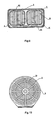
- Fig. 10 shows a schematic view of a further embodiment of a circular enclosure according to the present invention.
- the enclosure 5 is circular. Its bottom is flat (for being tightly attached to the surface of the integrate circuit chip).
- This example has excellent heat transfer efficiency.
- An enhanced cooling fan can be easily mounted on the circular enclosure and further improves the heat transfer rate.
- a guiding cover 53 which is used for introduce the cooling flow into the tubular thin-walled fluid channels 6, is mounted at the edge of the enclosure 5.
- the shape of the guiding cover 53 is similar to the enclosure 5 (as shown in Fig. 11 ).
- the inner side of the guiding cover 53 is a taper, i.e. the outer side is larger than the inner side.
- three layers of reinforcement plates 54 are provide in the sealed space 51.
- the shape of these reinforcement plates 54 is same as that of orthogonal projection of the sealed space 51 against the enclosure 5 in the axial direction, i.e. same as the shape of the end panels 7.
- These reinforcement plates are arranged parallel to the end panels 7. Holes or gaps, which are provided for the flow of working fluid, but not affect circular movement of the phase change, are formed in the reinforcement plates 54.
- connection manner in Fig. 12 may be applied for the connection of the edges of the end panels with the edges of enclosure and with the edges of tubular thin-walled fluid channels (only the connection of the end panels to the enclosure shown in Fig).
- the edge of end panel 7 is connected with the enclosure 5 by saddle joint, and the connection portions can be fixed by welding or adhering.
- the edges of end panels and tubular thin-walled fluid channels may also be connected in this manner.
- This connection is suitable for producing some heat pipe radiators for heat generating electronic components on an industrial scale. Moreover, larger sealed space is obtained in this manner, which is advantageous for the evaporation heat transfer.
- the high efficiency of heat transfer of the present invention is also attributed to the optimization of the arrangement of thermal fins.
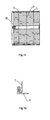
- the embodiments made from sheet metals of the present invention are shown in Fig.13 .
- Fig.13 shows an embodiment of the arrangement of thermal fins, in which the thermal fins 61 are made from the thin metal plate.
- the metal plate is continuously bended according to "Z" shape, and the thermal fins 61 are formed as thermal fins groups arranged in the tubular thin-walled fluid channel 6.
- a support plate 63 is provided between the thermal fins 61.
- This support plate 63 is made of metal and vertically passes through the thermal fins 61.
- the support plate 63 is fixed to the inner wall of the tubular thin-walled fluid channel 6 by welding top and bottom edges to the tubular thin-walled fluid channel 6. At the same time, the thermal fins 61 and support plate 63 is tightly connected by welding.
- the bended ends of the thermal fins 61 are tightly connected with the inner wall of tubular thin-walled fluid channel 6 by welding.
- the support plate 63 serves as a rib.
- the support plate 63 is made of metal material and tightly connected with thermal fins 61, the efficiency of heat transfer is improved.
- the thin thermal fins 61 further increase the effective heat transfer area.
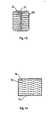
- Fig. 14 shows another embodiment of arrangement of the thermal fins.
- thermal fins 61 made of sheet metals are wavy. They are arranged in parallel as a group and fixed to the inner wall of tubular thin-walled fluid channel 6.
- Each thermal fin is provided with multiple upright thorns 611.
- the wavy thermal fins can make the cooling fluid fluctuant, prolong the contact time with the surfaces of thermal fins 61 and enhance capability of the heat transfer.
- the upright thorns 611 can bring on the phenomenon of turbulent flow of cooling fluid, so that the cooling fluid can take more heat energy away.
- some perforated holes for cold liquid passing through may be formed at the surfaced of thermal fins 61, so as to increase the efficiency of heat transfer as much as possible.
- the two embodiments shown in Fig. 13 and Fig. 14 not only increase the area for heat transfer, but also provide space volume for cooling fluid to flow through in the tubular thin-walled fluid channel 6 .
- This space volume is often more than two times of the volume of sealed space.
- heat pipe radiator of small volume used for components is desired, and the heat transfer area can not be enlarged limitlessly, the space volume for the cooling fluid to flow through can be increased as much as possible.
- outside tubular fluid channels 58 made of material of excellent thermal conductivity, are fixedly mounted to the surfaces of the enclosure 5.
- the axial line of outside tubular fluid channels 58 is parallel to that of tubular thin-walled fluid channel 6.
- Thermal fins 61 are fixedly attached to the inner wall of outside tubular fluid channels 58.
- the arrangement of thermal fins 61 in outside tubular fluid channels 58 may adopt the manner as shown in Fig. 13 , but parallel arrangement is also applicable.
- Thermal fins 61 absorb the heat energy of the outside surface of the enclosure 5 and significantly increase the heat transfer area of the enclosure 5, thus speed up the heat transfer rate and improve the heat transfer efficiency.
- the enclosure of this invention can be made of metal material, and engineering plastic can also be used to produce the enclosure in quantity.
- engineering plastic When the engineering plastic is adopted, a heat conductive plate may be fixed to the enclosure, and get the heat conductive plate and the surface of heat generating electronic components integrated closely, in order to decrease the thermal resistance.
- the heat conductive plate can be directly embedded in the enclosure, or allows a concave formed at the surface of the enclosure and the heat plates as the bottom surface, so that the heat plates are stretched into the sealed space and thus decrease the thermal resistance of conventional manner of direct contact.
- Fig. 16 shows an embodiment, in which the heat conductive plate is stretched into the sealed space. It can be seen from this figure that a concave 55, which can be embedded in an integrated circuit ship (CPU chip), is formed at the bottom of enclosure 5. The bottom surface of the concave 55 is the heat conductive plate 56.
- the heat energy generated by the chip can be easily dissipated through the working liquid and extremely high efficiency of heat transfer is achieved.
- the heat conductive plate 56 can be made from metal plate with excellent thermal conductivity, and can also be made from organic soft plate.
- the organic soft plate is able to tightly contact the surface of chips under installation pressure, and allows the heat energy to be rapidly transferred to the working fluid 52.
- the heat conductive plate 56 and the concave 55 can be made in rectangle, circle or the like, according to the shape of heat generating electric component. Moreover, multiple concaves 55 can be formed in the enclosure 5, resulting in a heat pipe radiator of heat generating electronic component used for integrated heat transfer.
- the heat generating part thereof can be directly immersed in the working fluid.
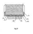
- the embodiment is described hereinafter.
- a hole 57 that holds a base plate 9 for components with size matching for the hole is formed at the bottom of the enclosure 5.
- the base plate 9 for components is hermetically connected with enclosure at the edge thereof.
- An Integrated electronic circuit 91 is provided at the surface of base plate for components 9 located in the sealed space 51. Multiple pins 92 of the integrated electronic circuit 91 can be protruded out of the base plate for components 9, and can be directly attached to a circuit board.
- the Integrated electronic circuit 91 is directly immersed in the working liquid 52 and the wick 8 is coated on the surface of the integrated electronic circuit 91.
- the wick 8 can be made of electrically insulated non-metal material, and the working liquid is also electrically insulated.
- the wick 8 and the working liquid are chemically and electronically compatible with the integrated electronic circuit 91.
- the other structures of this embodiment are same as that of the above described embodiments.
- the heat generated by the integrated electronic circuit 91 during using is directly transferred to the working liquid 52, which maximizes the heat transfer efficiency and thus eliminates the phenomenon of thermal resistance.
- the integrated electronic circuit 91 can be formed at the surface of the base plate for components 9, and then the base plate for components 9 is hermetically fixed to the hole 57 formed on the enclosure 5 in advance. Finally, the sealed space 51 is evacuated and infused with working fluid 52.
- multiple base plates for components 9 can be installed at the surface of enclosure 5, resulting in a heat pipe radiator for integrated heat generating electronic components having multiple chips.
- This embodiment can also be used to produce high power transistor element with its own heat pipe for heat generating electronic components and heat pipe radiators for integrated heat generating electronic components having multiple transistor elements.
- the P-N junctions are fixedly attached to the surface of base plates for components 9, so as to allow the heat generated by P-N junctions can be rapidly dissipated through the working liquid 52.
- the phenomenon that the heat energy can only be exported by the insulated material of junction base and that the destruction of transistors resulted from bad heat transfer is eliminated.
Landscapes
- Engineering & Computer Science (AREA)
- Life Sciences & Earth Sciences (AREA)
- Sustainable Development (AREA)
- Physics & Mathematics (AREA)
- Thermal Sciences (AREA)
- Mechanical Engineering (AREA)
- General Engineering & Computer Science (AREA)
- Cooling Or The Like Of Semiconductors Or Solid State Devices (AREA)
- Cooling Or The Like Of Electrical Apparatus (AREA)
Description
- The present invention relates to a radiator, especially an integrated heat pipe radiator formed by adjusting the arrangement of thermal fins wick and the overall heat pipe and having a three dimensional condensable heat transfer network. The radiator can be used for the heat transfer of electronic components. A heat pipe radiator as described in the preamble portion of patent claim 1 is known from
US 4 633 371 A . - With the rapid development of electronics and electric power technologies, especially the significantly increased integrity of integrated circuits, the heat transfer of electronic components has become one of the critical problems that limit the operating speed and output power of electronic appliances.
- For example, the integrity of a computer CPU was increased proximally 20,000 times within 30 years, and the heat flow generated has reached an extent of 100W/cm2. Moreover, this value will increase continuously, with the increase of the integrity of integrated circuits.
- It is well known that the reliability and life time of a computer are closely related to the working temperature thereof, and that the higher the integrity, the more heat energy is generated. It is also known that the normal internal working temperature of a computer chip is no more than 130°C, and the reliability will be decreased by 3.8% as a result of every degree increase. If the heat energy can not be dissipated in time, the working reliability of a computer can not be guaranteed and the computer may operate abnormally. As for computer research and development organizations, if they can not effectively solve the problem of the heat energy generated by chips and other electronic components during working, it is impossible for them to develop data processing devices with higher speed, higher power and smaller volumes. Nowadays, the common method for heat transfer of computers and other electronic components comprises arranging comb-like heat transfer plates made of an aluminium alloy on the bodies of chips or other electronic components so as to acquire a larger heat transfer area. At the same time, the heat energy is dissipated by cooling fans, so as to decrease the temperature. This method has the advantages of simplicity and cheapness, but it is only applicable to the heat transfer of components used in low calculating speed, low power electronic appliances.
- In 1998, US Sandia National Laboratories applied the heat pipe technology to the heat transfer of computer chips and obtained good results.
-
Fig.1 shows a radiator device with a heat pipe currently used. It comprises an enclosure body 1. The bottom plate of the enclosure body 1 is mounted with densely distributedthermal fins 2 made from thin metal pieces. Heat pipes 3 (the number may be two or three) are laid on the bottom plate of the enclosure body 1. Thepipes 3 pass through the bottom of the thermal fins, extend upwards, then are curved by 180 degrees and get into the top of thethermal fins 2. All thethermal fins 2 are tightly attached to theheat pipe 3. A working liquid, which is vaporizable when heated and condensable when cooled, is disposed in theheat pipes 3. When the enclosure body 1 is mounted on a chip, the heat energy generated by the chip causes the working liquid in heat pipes laid on the bottom plate in the enclosure body 1 to be evaporated. The heat energy enters theheat pipes 3 located on the top of thethermal fins 2 along with the evaporated working liquid, and condensable due to low temperature, while heat energy transferred outside through thethermal fins 2. If an enhancedcooling fan 4 is mounted on the top of thethermal fins 2, the heat energy will be transferred outward more easily. - Because heat pipes have extremely high heat transfer efficiency, the heat energy generated by chips can be rapidly transferred to distal thermal fins, so as to achieve the heat transfer. This method of heat transfer has higher heat transfer efficiency than that of prior comb-like heat transfer plates. As a rule, the temperature in a position distal to a chip is lower and the temperature in a position proximal to the chip is higher. This phenomenon of temperature gradient wastes a mass of heat transfer area, which will not obtain higher transfer efficiency. However, heat pipes can overcome the disadvantage of poor heat transfer effect of the comb-like heat transfer plates.
- Though the heat pipe radiator device in
Fig. 1 shows better heat transfer effect, the thermal fins can not be thin enough, when considering the deficiency of the structure (there are high resistances between heat source and bottom plate, between heat pipe and bottom plate, as well as heat pipe and fins) and the strength of the radiator. However, thicker fins will not only waste material and occupy the limited space, but also can not acquire larger thermal transfer area. Therefore, this method can not meet the heat transfer requirements of super large integrated circuits, high power electronic devices and high speed chips, which limits their application and development to some extent. - In a similar way, a chip radiator device is known utilizing the heat pipe theory. It is a hollow enclosure, with a working liquid infused inside. Multiple comb-like thermal fins are extendedly disposed on the surface of the enclosure. When the hollow enclosure is mounted on a surface of a chip, the heat energy of the chip is transferred into the hollow enclosure. The evaporated working liquid transfers the heat energy to the surface of the hollow enclosure, and the heat energy is then dissipated outside by the multiple comb-like thermal fins. This chip radiator shows better heat transfer efficiency than that of the heat pipe radiator device shown in
Fig. 1 . But it is still limited by the inside evaporation space and the size of thermal transfer surface, and can not sufficiently meet the heat transfer requirement of modem high speed chips and larger scale integrated circuits in research and development. -
US 6 005 772 A discloses a cooling apparatus. A radiating part mounted on a refrigerant tank is made by stacking refrigerant tubes and fins alternately. A first header and a second header are provided at the ends of the refrigerant tubes. When the cooling apparatus is used in a vertical attitude, the first header is positioned above the liquid surface of refrigerant inside the refrigerant tank, and the second header is positioned below the liquid surface. -
US 6 588 498 B1 discloses a thermosiphon for cooling an electronic device having a mean width of dimension "b", which comprises a boilerplate having a top surface and including a plurality of pyramid shaped fins projecting upwardly from the top surface. -
US 6 321 831 B1 discloses a cooling apparatus which includes a refrigerant tank containing boiling and condensing refrigerant and a radiator for cooling the refrigerant. The radiator is connected to the refrigerant tank on a front surface thereof, and hot objects to be cooled are attached to a heat-receiving surface formed on a rear surface of the refrigerant tank. The refrigerant is circulated in the apparatus so that the refrigerant is vaporized in the refrigerant tank and condensed in the radiator. The radiator is connected to the refrigerant tank by inserting a pair of header tanks thereof into the refrigerant tank. The insertion length is controlled to obtain good heat conductivity between the radiator and the refrigerant tank and to avoid deformation of a radiator fin contacting the refrigerant tank. Holes for mounting a substrate carrying the hot objects may be made on enlarged portions of a cover plate closing the refrigerant tank. -
US 2002/189791 A1 discloses a liquid cooler including a body and a cover attached on the body. The body includes a base with a first cavity accommodating liquid, a central hollow cylinder having a passage in communication with the first cavity, and a plurality of vertical tubes in communication with the first cavity. A plurality of fins extends outwardly from the hollow cylinder. The cover defines a second cavity in communication with the passage and the tubes. The liquid within the first cavity is heated by a heat-generating electronic device and moved to the second cavity through the tubes. Heated liquid which has reached the second cavity flows down through the passage along an inner surface of the hollow cylinder and returns back to the first cavity. The heated liquid is cooled by the fins conducting heat away from the hollow cylinder. -
US 4 633 371 A discloses a heat pipe heat exchanger for large scale integrated circuits. The heat pipe means is mounted on the substrate which supports the integrated circuit. The heat is conducted by the heat pipe means away from the integrated circuit to a surface area for dissipating heat. A plenum supplies a cooling medium across the surface area of the heat pipe means for removing the heat. An enclosing means for enclosing the surface area of the heat pipe means forms channels across the surface area for receiving the cooling medium supplied from the plenum. - Accordingly, this document discloses a heat pipe radiator for heat generating electronic components comprising a tubular enclosure, a tubular thin-walled fluid channel arranged in the enclosure with the edge hermetically connected with that of the enclosure by an end panel, thermal fins are fixedly arranged in the tubular thin-walled fluid channel.
-
US 5 998 863 A -
US 2002/056908 A1 discloses an apparatus which can dissipate heat and include a top wall including a plurality of hollow fins, a bottom wall, and a plurality of side walls that define an inner cavity. A plurality of condenser regions can be located within the inner cavity, and each one of the plurality of condenser regions can be located within one of the plurality of hollow fins. The inner cavity also can include an evaporator region adjacent said bottom wall. -
US 2001/004934 A1 discloses a compressed mesh wick, a method for manufacturing the same, and a plate-type heat pipe including a compressed mesh wick. This document specifically discloses stacking multilayer woven metal meshes which are strip-shaped and repeatedly folded. -
US 6418017 B1 discloses a heat dissipating chassis member. It specifically discloses meshes, powder sintered wicks, grooved wicks. -
US 5647429 A discloses coupled, flux transformer heat pipes. It speciflcally discloses wicks having pores, wrapped screen wicks and composite wicks. - Therefore, there is a problem how to utilize the heat pipe theory to design and commercially produce radiators with high heat transfer efficiency to meet the higher requirements of heat transfer of electronic components, which has become one of the problems that should be solved imminently by the persons skilled in the field.
- The object of this invention is to overcome the problem of conventional radiators which can not meet the present requirements of heat transfer of electronic components and aren't able to be conditioned for the rapid development of modern electronic technology. In other words, this invention intends to provide a heat pipe radiator for heat generating electronic components, which takes advantage of heat pipe theory that working liquid can rapidly take away heat energy.
- This object is accomplished with a heat pipe radiator as claimed in claim 1. Features of preferred embodiments of the invention are claimed in the dependent claims.
- Due to the arrangement of cooling network in three dimensions, the present invention achieves an optimized match combination of heat energy generated by the heat resources and heat transfer area, and thus provides a new means of solution to solve the heat transfer of the electronic components.
- According to the present invention, the thermal fins increase the heat transfer area significantly. The effect of the heat-transfer by the thermal fins will be even better when a cold wind blows through the tubular thin-walled fluid channel.
- During production, the shape of the enclosure will be formed as a rectangular, circular or hexagonal tube or in any other shapes according to the practical requirement.
- The wick can be made from multilayer fiber woven meshes, or can be made from terrace multilayer metal meshes. A plate having microcellular structure by powder sintering may also be used. The wick can be coated on the surface of the inner wall of the enclosure by adhering or welding.
- The wick can be produced by another means. The wick can be a strap made from metal or organic sheets by continuously and repeatedly bending or curving. Some pores are formed at the surface of the sheets, which are circumferentially attached to the inner wall of the enclosure by welding or adhering. The wick produced in this manner not only has the property that the wick absorbs the working liquid described above, but also can assist heat transfer and thermal conduction itself, due to its excellent thermal conductivity itself. This wick allows the working liquid far from the heat source to be evaporated directly and rapidly, so that the thermal conductive rate is increased and thus the heat transfer efficiency of entire heat pipe radiator of heat generating electronic components is significantly improved.
- In these technical solutions, one or more tubular thin-walled fluid channels may be made depending on the actual requirements. A communicated sealed space is formed between the tubular thin-walled fluid channel and the inner wall of the enclosure and between the outsides of the multiple tubular thin-walled fluid channels by hermetically connecting the edges of end panels to the edges of multiple tubular thin-walled fluid channels and the edges of enclosure.
- When the volume of enclosure and the number of the layers of thermal fins are determined, multiple tubular thin-walled fluid channels will decrease the total heat transfer area of the thermal fins, but will increase the volume of sealed space and benefit the evaporation heat transfer of the working liquid. The determination of the number of tubular thin-walled fluid channels depends on the match requirement between the heat energy generated by the heat source and the heat energy dissipated. Therefore, the optimized match design can be achieved by adjusting the numbers of tubular thin-walled fluid channels. In addition, the limited space can be effectively utilized by adjusting the sectional shape of the tubular thin-walled fluid channels, such as rectangle or circle or hexagon or other shapes, such that a better match value of the rate of the volume in tubular thin-walled fluid channels for cooling fluid to flow through and the volume in sealed space can be achieved. Experiments show that the volume for cooling fluid to flow through should be more than or equal to 2 times of the volume of the sealed space.
- The tubular thin-walled fluid channel can be made of metal material with excellent thermal conductivity. In order to secure the thermal fins, support rods or support plates can be arranged in the tubular thin-walled fluid channels. The support rods or support plates pass through the thermal fins and are fixed to the inner wall of said the tubular thin-walled fluid channels So that the thermal fins are tightly connected with the support rods or support plates. Thin-wall heat pipes made of metal material can also be provided in the tubular thin-walled fluid channels. The thin-wall heat pipes pass through said thermal fins and are tightly connected with said thermal fins. The both ends of the thin-wall heat pipes are fixed to the inner wall of the tubular thin-walled fluid channels and communicated with the sealed space. Therefore, the thin-wall heat pipes can not only fix the thermal fins, but also transfer the heat energy to the thermal fins. The effect is equal to the increased volume of the sealed space and the increased area for transferring heat energy to the thermal fins. As a result, excellent efficiency of heat transfer is obtained.
- In these solutions, the end panels are critical components for sealing the sealed space. In order to reliably secure the sealing and to be easy for production, flanges useful for welding or adhering to the inner wall of enclosure and the outer surfaces of tubular thin-walled fluid channels can be outwardly formed from the surface edges of the end panels inner wall, which can be arranged inward or outward to the sealed space. The arrangement of flanges can improve the strength of heat pipe radiator for heat generating electronic components, and are suitable for producing in quantity.
- The thermal fins are made from sheet metals. The thermal fins can be wavy or can be a thermal fins group formed by continuously folding the sheet metals according to "Z" shape. Some penetrating holes can be formed at the surface of the thermal fins for cooling fluid to flow through. According to the invention, some upright thorns that cause the turbulent flow of the cooling fluid are vertically arranged at the surface of the thermal fins so as to further improve the heat transfer effect.
- In order to further increase the heat transfer efficiency, an enhanced cooling fan is provided outside the tubular thin-wall fluid channel of the heat pipe radiator for heat generating electronic component. For this propose, a guiding cover, which is used to introduce the cold flow blew from the cooling fan into the tubular thin-wall fluid channels, is suitably mounted at the edge of enclosure. The shape of the guiding cover is similar to that of the enclosure or the tubular thin-wall fluid channels.
- To make full use of the heat transfer capability of the working liquid in the sealed space and of the integrated heat-dissipating capability of the thermal fins, outer tubular fluid channels made of material with excellent heat conductivity are fixedly attached to the outside surface of the enclosure. The axial lines of the outer tubular thin-wall fluid channels are parallel to those of the said tubular thin-wall fluid channel. Thermal fins are provided at the internal walls of the outer tubular fluid channels. The thermal fins in outer tubular fluid channels absorb the heat energy of the outside surface of the enclosure, so that the heat transfer area outside the enclosure is increased significantly. Thus the heat transfer rate is speeded up and heat efficiency is improved.
- The technical solutions can be used to dissipate heat energy from multiple heat generating electronic components simultaneously. At the same time, in order to increase the heat transfer efficiency from heat generating electronic components to the sealed space, one or more heat-conductive plates, which are able to be tightly attached to the heat-dissipating surface of the heat generating electronic components, are fixedly arranged on the enclosure. The heat-conductive plates are embedded at the surface of the enclosure. Alternatively, a special concave is opened at the surface of the enclosure and the heat-conductive plate is used as the bottom surface of the special concave. The heat-dissipating surface of the outer heat generating electronic component can be engaged into the special concave, and tightly attached to the heat -conductive plate. The heat-conductive plates are made from metal plate or organic soft plate material with excellent thermal conductivity. The heat plates can be made in rectangle, circle, or any other matching shapes according to the shapes of the heat-dissipating surfaces of the heat generating components.
- In order to meet the requirements of higher heat transfer of the chips from the rapid development of super large scale integration technology, the present invention further provides a technical solution to directly dissipate heat from the integrated circuits themselves. At the same time, the technical solution provides good ways to directly dissipate heat from high power transistors and high frequency transistors. The detailed solution is as follows: based on the technical solutions described above, one or more holes are formed at the enclosure and a base plate for components with size matching for the hole is embedded. The base plate for components is hermetically connected with the enclosure at the circumferential edge thereof. The integrated electronic circuit or inner chips of the electronic components is provided on the surface of the base plate located in the sealed space. Multiple pins of the integrated electronic circuit or inner chips of electronic components can be arranged on the surface of the base plate for components located outside the enclosure.
- The wick is applied on the inner chips of the integrated electronic circuit or electronic components. The working liquid is an electrical insulater material and chemically, electrically compatible with the material of inner chips of the integrated electronic circuit or electronic components.
- In this technical solution, the base plate can be the chip base board of the integrated circuits, and super large integrated circuits at its surface is directly arranged in the sealed space and directly contacted with the working liquid, so that the transfer of heat energy is rapid and has no thermal resistance. Therefore, the capability to dissipate heat energy from chips is improved as much as possible, the working stability is ensured and the life time of chips is prolonged. In a similar way, the bottom board of the high power transistors can also be formed as the base plate of components. The P-N junctions fixed on the surface of the bottom board of high power transistors is also directly contacted with the working liquid. Thus, the phenomenon that the heat energy can only be exported by the insulater material of junction base with low heat transfer efficiency of conventional transistors is eliminated, which significantly increases the heat transfer efficiency of transistors and prolonged the life time of transistors, especially the reliability and life time of high power transistors and high frequency transistors is improved.
- It can be known from the above mentioned technical solutions that, based on the theory of heat pipe transferring heat, the present invention makes the thermal fins ultra-thinned, with a high density and obtains much more heat transfer area than that of conventional heat pipe devices, because a three dimensional heat transfer network is formed by forming a sealed space for the evaporation heat transfer of working liquid by arranging tubular thin-walled fluid channels in the tubular enclosure and making use of the thermal fins provided in the tubular thin-walled fluid channels. The optimized match is obtained between the heat energy generated by the electric components and the heat transfer efficiency of radiator. The heat transfer efficiency of radiator is improved without increasing the volume of the radiator. Moreover, the present invention is featured by its simple structure, high heat transfer rate, uniform heat transfer, easy to use and high working reliability, and it can be manufactured in various forms to meet the requirements of different devices according to the actual situation of the electric components.
- In addition, the present invention also provides effective solutions of direct heat transfer for the problem of heat transfer of present and future super large intergraded circuits and various heat generating electronic components.
-
-
Fig.1 is a structural schematic view of a heat pipe radiator device currently used; -
Fig.2 is a structural schematic view of the heat pipe radiator for heat generating electronic components according to the present invention; -
Fig.3 is a structural schematic view of an end panel of the heat pipe radiator shownFig.2 ; -
Fig.4 is a structural schematic view of an exemplary embodiment of the fluid sucking wick according to the present invention; -
Fig.5 is a structural schematic view of another exemplary embodiment of the fluid sucking wick according to the present invention; -
Fig.6 is a structural schematic view of an exemplary embodiment of the flaky fluid sucking wick according to the present invention; -
Fig.7 is structural schematic view of an another exemplary embodiment of the flaky fluid sucking wick according to the present invention; -
Fig.8 is a structural schematic view of a further exemplary embodiment of the flaky fluid sucking wick according to the present invention; -
Fig. 9 is a structural schematic view of an exemplary embodiment according to the present invention; -
Fig. 10 is a structural schematic view of another exemplary embodiment according to the present invention; -
Fig. 11 is a structural side view of the exemplary embodiment shown inFig. 10 ; -
Fig. 12 is a schematic view of another connection method of the end panels according to the present invention; -
Fig. 13 is a structural schematic view of an exemplary embodiment of the thermal fins according to the present invention; -
Fig. 14 is a structural schematic view of another exemplary embodiment of the thermal fins according to the present invention; -
Fig. 15 is a structural schematic view of an exemplary embodiment with outer tubular fluid channels according to the present invention; -
Fig. 16 is a structural schematic view of an exemplary embodiment with reduced thermal resistance according to the present invention; -
Fig. 17 is a structural schematic view of an exemplary embodiment capable of eliminating thermal resistance and directly dissipating heat energy according to the present invention. - The present invention is further described hereinafter with detailed embodiments, in reference to the accompanying drawings.
-
Figure 2 is a theory structural schematic view of a heat pipe radiator of heat generating electronic components provide by the present invention. This radiator comprises a tubular enclosure 5(it's rectangular in this figure, but may be made in other shapes). A tubular thin-walled fluid channel 6 is disposed inside theenclosure 5. Also, the said tubular thin-walled fluid channel 6 is rectangular. The tubular thin-walled channel 6 and theenclosure 5 are hermetically connected along the edges by two front and back parallel end panels 7so that a sealedspace 51 is formed between the inner wall ofenclosure 5 and the outside of tubular thin-walled fluid channel 6. This sealedspace 51 is evacuated and its inside is infused with a workingfluid 52, which is vaporizable when heated and condensable when cooled. - The tubular thin-
walled fluid channel 6 is made from sheet metals having excellent thermal conductivity, and multilayerthermal fins 61 are securely attached inside. Multilayerthermal fins 61 are arranged densely and in parallel, with their edges connected to the inner wall of tubular thin-walled channel 6. When cooling liquid passes through the tubular thin-walled channel 6, heat energy is dissipated through thethermal fins 61. - Inside the sealed
space 51, afluid sucking wick 8 is coated around the internal surface ofenclosure 5. The inside and surface of thefluid sucking wick 8 have interstices, which are capable of causing capillary forces to allow liquid absorbed on its surface and spread through its surface. Thefluid sucking wick 8 can be affixed on the internal surface of theenclosure 5 by welding or adhering, with part of which immersed in the working liquid. - An
infusion hole 71 used to vacuum the sealed space and infuse the working liquid is provided on theend panel 7. Thisinfusion hole 71 is sealed off after the sealed space is vacuuming and infused with the workingliquid 52. - When the heat pipe radiator of the electric component above described is in use, it is mounted on a surface of a heat generating electronic component (e.g. CPU chip). The heat energy produced by the heat generating electronic component is transferred to working
liquid 52 through the bottom of theenclosure 5, and then the workingliquid 52 is evaporated and the unheated portion flows to the evaporated portion to compensate. The evaporated workingliquid 52 moves upward along the inside of sealedspace 51, and performs heat exchanging with the outside of tubular thin-walled fluid channel 6. The heat energy is transferred to multilayerthermal fins 61. The evaporated working fluid giving offheat energy 52 is condensable to be liquid again due to decreased temperature, and falls to the original position to continuously compensate the evaporated portion. Thus, a circular movement of phase change of workingfluid 52 is formed in the sealedspace 51. During this circular movement of phase change, the heat energy of heat generating electronic component is dispelled rapidly. - Inside the tubular thin-
walled fluid channel 6, compared with the heat transfer area of heat generating electronic component, the densely arranged multilayerthermal fins 61 acquired much more heat transfer area, so as to ensure the heat energy dissipated timely. - When the electronic component is working during movement (e.g. transportation) or at the status of incline or upside down, working
liquid 52 deviates from the position of heat generating electronic component. Then thewick 8 absorbs the workingliquid 52 by using the capillary forces produced by its inside interstices, and allows the workingliquid 52 to spread to the position of heat generating electronic component to provide evaporation heat transfer. Thus, it is ensured that circular movement of phase change of the working liquid will not be interrupted. - The shape of
end panel 7 is adopted from the shape formed between the outside of tubular thin-walled fluid channel 6 and the inside ofenclosure 5. In the above embodiment, the shape of theend panel 7 is a rectangular-framed. For the sake of easy assembly, fastness and good sealing, the section of theend panel 7 can be concave, as shown inFig.3 . InFig.3 , aflange 72 is protuberantly provided around the surface edge of theend panel 7 toward the inside of said sealed space. Theend panel 7 can be easily welded or adhered to the inside of enclosure or the outside surface of the tubular thin-walled fluid channel by thisflange 72. It has the advantages of easy procession and good sealing. The protruding direction of theflange 72 may be toward the outside of sealed space, but it will reduce the volume of the sealed space. - The
wick 8 can be produced in many forms.Fig. 4 shows a wick produced by welding stacked multilayer metal meshes 81. Between the multilayer metal meshes 81 and the multilayer metal meshes 81 themselves have abundant interstices, which can result in better liquid sucking effect. -
Fig. 5 is a part view of porous wick produced by a powder sintering process. This wick makes use ofmicro-pores 82 inside and at the surface thereof to produce capillary forces to suck liquid. -
Fig. 6 shows a strip-shaped wick, which is made by continuously bending sheet metals having excellent thermal conductivity to and for according to its "U" shape. There are many "U" shaped grooves are formed in the strip-shaped wick.Pores 83 are opened at the surface of sheet metals of this strip-shaped wick. Thepores 83 can be rectangular or circular aperture opening, which can be arranged inward or outward. This strip-shaped wick can be welded to inner wall of enclosure. Compared with other wicks, it has good capillary sucking force. Moreover, because it is an excellent thermal conductor itself, it can assist thermal conduction, rapidly transfer heat energy to the distal working fluid and perform evaporation heat transfer at larger area through thepores 83 at the surface thereof. Therefore, compared with wicks of multilayer metal meshes and porous wick produced by powder sintering process, it achieves a better heat transfer effect. The strip-shaped wick made from sheet metals can also be the strip-shaped wick made by continuously bending sheet metals having excellent thermal conductivity to and fro according to "V" shape, as shown inFig. 7 ; or by continuously bending sheet metals having excellent thermal conductivity to and fro according to "Ω" shape, as shown inFig.8 . InFig.7 and Fig. 8 , pores 83 are formed at the surfaces of these two strip-shaped wicks, and thus the surfaces can be used for working liquid to be evaporated. -
Pores 83 and multiple grooves of "U" shape, "V" shape or "Ω" shape naturally formed inFig.6, Fig.7 and Fig.8 can allow the working fluid to spread inside easily. - In order to facilitate the evaporation and spreading of working fluid, the end openings of grooves of "U" shape, "V" shape and "Ω" shape can be sealed off.
- Beside the function of transporting liquid of conventional wicks by capillary forces, these strip-shaped wicks made from sheet metals also have two special functions, which make the present invention more effective. The functions are as follows:
- Firstly, when the wicks are welded to the inner wall of the enclosure, they can significantly improve the strength of the enclosure because of the strong structure of themselves. Thus, the enclosure can be made of thin material, which can not only further reduce the thermal resistance and speed up the conduction, but also decrease the weight of the enclosure, without lowering the mechanical strength of the enclosure. It will be important for the development, production and application of future miniaturized electronic devices, especially when the electronic devices used in sophisticated aviatic apparatus.
- Secondly, because the wicks are formed by bending the sheets and have plenty of pores at the surface thereof, when the wicks are welded to the enclosure and transfer the heat energy, as a rule the temperatures of the edges of turning and pores are higher, which allows the working liquids of these positions to be boiled more easily, and result in an effect of enhanced boiling. Thus the heat energy can be dissipated more rapidly through the boiling.
-
Fig. 9 shows an embodiment having two tubular thin-walled fluid channels provided by the present invention. The two tubular thin-walled fluid channels are formed in rectangle according to the shape of theenclosure 5. The shapes of end panels (not shown) are same as the shape formed between the two tubular thin-walled fluid channels 6 and theenclosure 5, and the method of sealing is same as the above-described principle structure, so detailed description is not described any more. - In this embodiment, multiple thin-
walled heat pipes 62 made of metal material are arranged inside the tubular thin-walled fluid channel 6. These thin-walled heat pipes 62 vertically pass through thethermal fins 61 and are fixedly attached to thethermal fins 61. The both ends of the thin-walled heat pipes 62 are fixed to the inner wall of the tubular thin-walled fluid channel 6 and their inner cavity are communicated with the sealedspace 51. The establishment of thin-walled heat pipes 62 provides support for the densely arrangedthermal fins 61, improves the strength ofthermal fins 61, and at the same time increases the heat exchanging area, On the other hand, the establishment of thin-walled heat pipes 62 also increases the volume of the sealedspace 51, which is more advantageous for the evaporated working liquid to transfer heat energy to the environmental and speeds up the rate of phase change from gas to liquid, and thus improves the heat transfer efficiency of the whole heat pipe radiator of the heat generating electronic component. -
Fig. 10 shows a schematic view of a further embodiment of a circular enclosure according to the present invention. In this example, theenclosure 5 is circular. Its bottom is flat (for being tightly attached to the surface of the integrate circuit chip). There are 10 tubular thin-walled fluid channels like orange petals arranged in theenclosure 5. Inside the tubular thin-walled fluid channel 6, thethermal fins 61 are densely arranged in circular arc. This example has excellent heat transfer efficiency. An enhanced cooling fan can be easily mounted on the circular enclosure and further improves the heat transfer rate. In order to achieve better heat transfer efficiency of the cold flow produced by the enhanced cooling fan, a guidingcover 53, which is used for introduce the cooling flow into the tubular thin-walled fluid channels 6, is mounted at the edge of theenclosure 5. The shape of the guidingcover 53 is similar to the enclosure 5 (as shown inFig. 11 ). The inner side of the guidingcover 53 is a taper, i.e. the outer side is larger than the inner side. When the enhanced cooling fan is mounted outside the guidingcover 53 and delivers gas into the tubular thin-walled fluid channels 6, the taper inclined surface the guidingcover 53 can introduce cold gas into the tubular thin-walled fluid channels 6 as much as possible, which improves the efficiency of the heat transfer. - In this embodiment, in order to improve the structural strength of the entire radiator, three layers of
reinforcement plates 54 are provide in the sealedspace 51. The shape of thesereinforcement plates 54 is same as that of orthogonal projection of the sealedspace 51 against theenclosure 5 in the axial direction, i.e. same as the shape of theend panels 7. These reinforcement plates are arranged parallel to theend panels 7. Holes or gaps, which are provided for the flow of working fluid, but not affect circular movement of the phase change, are formed in thereinforcement plates 54. - In the embodiment of the above described heat pipe radiators for heat generating electronic components, the connection manner in
Fig. 12 may be applied for the connection of the edges of the end panels with the edges of enclosure and with the edges of tubular thin-walled fluid channels (only the connection of the end panels to the enclosure shown in Fig). In this figure, the edge ofend panel 7 is connected with theenclosure 5 by saddle joint, and the connection portions can be fixed by welding or adhering. The edges of end panels and tubular thin-walled fluid channels may also be connected in this manner. This connection is suitable for producing some heat pipe radiators for heat generating electronic components on an industrial scale. Moreover, larger sealed space is obtained in this manner, which is advantageous for the evaporation heat transfer. - The high efficiency of heat transfer of the present invention is also attributed to the optimization of the arrangement of thermal fins. The embodiments made from sheet metals of the present invention are shown in
Fig.13 . -
Fig.13 shows an embodiment of the arrangement of thermal fins, in which thethermal fins 61 are made from the thin metal plate. The metal plate is continuously bended according to "Z" shape, and thethermal fins 61 are formed as thermal fins groups arranged in the tubular thin-walled fluid channel 6. Asupport plate 63 is provided between thethermal fins 61. Thissupport plate 63 is made of metal and vertically passes through thethermal fins 61. Thesupport plate 63 is fixed to the inner wall of the tubular thin-walled fluid channel 6 by welding top and bottom edges to the tubular thin-walled fluid channel 6. At the same time, thethermal fins 61 andsupport plate 63 is tightly connected by welding. Also, the bended ends of thethermal fins 61 are tightly connected with the inner wall of tubular thin-walled fluid channel 6 by welding. Thus, the thinness of the metal plate used to manufacture thermal fins can be as small as possible, without affecting the structural strength. Actually, thesupport plate 63 serves as a rib. In addition, because thesupport plate 63 is made of metal material and tightly connected withthermal fins 61, the efficiency of heat transfer is improved. Moreover, the thinthermal fins 61 further increase the effective heat transfer area. -
Fig. 14 shows another embodiment of arrangement of the thermal fins. In this embodiment,thermal fins 61 made of sheet metals are wavy. They are arranged in parallel as a group and fixed to the inner wall of tubular thin-walled fluid channel 6. Each thermal fin is provided with multipleupright thorns 611. When cooling fluid flows through the tubular thin-walled fluid channel 6, the wavy thermal fins can make the cooling fluid fluctuant, prolong the contact time with the surfaces ofthermal fins 61 and enhance capability of the heat transfer. At the same time, theupright thorns 611 can bring on the phenomenon of turbulent flow of cooling fluid, so that the cooling fluid can take more heat energy away. - In addition, some perforated holes for cold liquid passing through may be formed at the surfaced of
thermal fins 61, so as to increase the efficiency of heat transfer as much as possible. - The two embodiments shown in
Fig. 13 and Fig. 14 not only increase the area for heat transfer, but also provide space volume for cooling fluid to flow through in the tubular thin-walled fluid channel 6 . This space volume is often more than two times of the volume of sealed space. When heat pipe radiator of small volume used for components is desired, and the heat transfer area can not be enlarged limitlessly, the space volume for the cooling fluid to flow through can be increased as much as possible. - When a space is big enough for heat transfer, another embodiment is provided by this invention, in which outside tubular fluid channels are attached to the outer side of the enclosure, as shown in
Fig. 15 . - In this Figure, three outside tubular
fluid channels 58, made of material of excellent thermal conductivity, are fixedly mounted to the surfaces of theenclosure 5. The axial line of outside tubularfluid channels 58 is parallel to that of tubular thin-walled fluid channel 6.Thermal fins 61 are fixedly attached to the inner wall of outside tubularfluid channels 58. The arrangement ofthermal fins 61 in outside tubularfluid channels 58 may adopt the manner as shown inFig. 13 , but parallel arrangement is also applicable.Thermal fins 61 absorb the heat energy of the outside surface of theenclosure 5 and significantly increase the heat transfer area of theenclosure 5, thus speed up the heat transfer rate and improve the heat transfer efficiency. - The enclosure of this invention can be made of metal material, and engineering plastic can also be used to produce the enclosure in quantity. When the engineering plastic is adopted, a heat conductive plate may be fixed to the enclosure, and get the heat conductive plate and the surface of heat generating electronic components integrated closely, in order to decrease the thermal resistance.
- The heat conductive plate can be directly embedded in the enclosure, or allows a concave formed at the surface of the enclosure and the heat plates as the bottom surface, so that the heat plates are stretched into the sealed space and thus decrease the thermal resistance of conventional manner of direct contact.
Fig. 16 shows an embodiment, in which the heat conductive plate is stretched into the sealed space. It can be seen from this figure that a concave 55, which can be embedded in an integrated circuit ship (CPU chip), is formed at the bottom ofenclosure 5. The bottom surface of the concave 55 is the heatconductive plate 56. With the arrangement that the concave 55 located in the sealed space, thewick 8 is coated on the other surface and the entire concave 55 is located in the sealed space, the heat energy generated by the chip can be easily dissipated through the working liquid and extremely high efficiency of heat transfer is achieved. - The heat
conductive plate 56 can be made from metal plate with excellent thermal conductivity, and can also be made from organic soft plate. The organic soft plate is able to tightly contact the surface of chips under installation pressure, and allows the heat energy to be rapidly transferred to the workingfluid 52. - The heat
conductive plate 56 and the concave 55 can be made in rectangle, circle or the like, according to the shape of heat generating electric component. Moreover,multiple concaves 55 can be formed in theenclosure 5, resulting in a heat pipe radiator of heat generating electronic component used for integrated heat transfer. - In order to completely eliminate the thermal resistance of heat generating electronic components during the thermal transfer, the heat generating part thereof can be directly immersed in the working fluid. The embodiment is described hereinafter.
- Referring to
Fig. 17 , ahole 57 that holds abase plate 9 for components with size matching for the hole is formed at the bottom of theenclosure 5. Thebase plate 9 for components is hermetically connected with enclosure at the edge thereof. An Integratedelectronic circuit 91 is provided at the surface of base plate forcomponents 9 located in the sealedspace 51.Multiple pins 92 of the integratedelectronic circuit 91 can be protruded out of the base plate forcomponents 9, and can be directly attached to a circuit board. The Integratedelectronic circuit 91 is directly immersed in the workingliquid 52 and thewick 8 is coated on the surface of the integratedelectronic circuit 91. In this embodiment, thewick 8 can be made of electrically insulated non-metal material, and the working liquid is also electrically insulated. Thewick 8 and the working liquid are chemically and electronically compatible with the integratedelectronic circuit 91. - The other structures of this embodiment are same as that of the above described embodiments. The heat generated by the integrated
electronic circuit 91 during using is directly transferred to the workingliquid 52, which maximizes the heat transfer efficiency and thus eliminates the phenomenon of thermal resistance. During the production, firstly the integratedelectronic circuit 91 can be formed at the surface of the base plate forcomponents 9, and then the base plate forcomponents 9 is hermetically fixed to thehole 57 formed on theenclosure 5 in advance. Finally, the sealedspace 51 is evacuated and infused with workingfluid 52. - With the above described manners, multiple base plates for
components 9 can be installed at the surface ofenclosure 5, resulting in a heat pipe radiator for integrated heat generating electronic components having multiple chips. - This embodiment can also be used to produce high power transistor element with its own heat pipe for heat generating electronic components and heat pipe radiators for integrated heat generating electronic components having multiple transistor elements. During production, only the P-N junctions are fixedly attached to the surface of base plates for
components 9, so as to allow the heat generated by P-N junctions can be rapidly dissipated through the workingliquid 52. Thus, the phenomenon that the heat energy can only be exported by the insulated material of junction base and that the destruction of transistors resulted from bad heat transfer is eliminated.
Claims (20)
- A heat pipe radiator for heat generating electronic components comprising a tubular enclosure (5), a tubular thin-walled fluid channel (6) arranged in the enclosure (5) with the edge hermetically connected with that of the enclosure (5) by an end panel (7);
thermal fins (61) are fixedly arranged in the tubular thin-walled fluid channel (6);
characterized in that
a sealed space (51) is formed between the inner wall of the enclosure (5) and the outside of the tubular thin-walled fluid channel (6); and the sealed space (51) is evacuated and infused with a working fluid (52) which is vaporizable when it meets heat and condensable when it meets cold;
the internal surface of the enclosure in the sealed space (51) is coated with a wick (8) which has interstices capable of causing capillary forces to absorb liquid and allowing the liquid to spread on the wick (8);
an infusion hole (71) used to evacuate the sealed space (51) and infuse the working liquid (52) is provided on the end panel or the enclosure (5), and it is sealed off after the sealed space (51) is evacuated and infused with the working liquid (52),
some upright thorns for causing turbulent flow of cooling fluid are vertically arranged at a surface of the thermal fins;
wherein the wick (8) is formed by stacking multilayer fiber woven meshes or multilayer metal meshes (81), or is plate-shaped with micro-pores (82) formed by powder sintering or the wick is strip-shaped made from metal or organic sheets by continuously and repeatedly folding or bending; pores (83) are formed at the surfaces of the sheets which are attached to the inner wall of the enclosure by welding or adhering. - The heat pipe radiator for heat generating electronic components as claimed in claim 1, wherein the enclosure (5) is a rectangular, circular or hexagonal tube made of the material with excellent thermal conductivity.
- The heat pipe radiator for heat generating electronic components as claimed in claim 1, wherein the strip-shaped wick is formed by repeatedly folding or bending the sheets according to "U" shape, "V" shape or "Ω" shape, so that many grooves of "U" shape, "V" shape or "Ω" shape are formed in the strip-shaped wick.
- The heat pipe radiator for heat generating electronic components as claimed in claim 3, wherein end surfaces of the grooves of "U" shape, "V" shape and "Ω" shape of the strip-shaped wick are sealed off.
- The heat pipe radiator for heat generating electronic components as claimed in claim 1, wherein the pores (83) are rectangular or circular or protruding aperture openings and evenly arranged at the surface of the sheets.
- The heat pipe radiator for heat generating electronic components as claimed in any one of claims 1-5, wherein the number of the tubular thin-walled fluid channels (6) is one or more; and the end panels (7) are hermetically connected to the edges of a plurality of tubular thin-walled fluid channels (6) and the edges of enclosure so that a communicated sealed space (51) is formed between the tubular thin-walled fluid channels (6) and the inner wall of the enclosure (5) and between the outsides of a plurality of tubular thin-walled fluid channels (6).
- The heat pipe radiator for heat generating electronic components as claimed in claim 6, wherein the tubular thin-walled fluid channels (6) are rectangular, circular or hexagonal tubes made of metal material with excellent thermal conductivity and the space volume in the tubular thin-walled fluid channels (6) for the cooling fluid to flow through is 2 times larger than that of the sealed space (51).
- The heat pipe radiator for heat generating electronic components as claimed in claim 6, wherein one or more support rods or support plates made of metal material are further arranged in the tubular thin-walled fluid channels (6); the support rods or support plates (63) pass through the thermal fins (61) and are fixed to the inner wall of the tubular thin-walled fluid channels (6); the thermal fins (61) are tightly connected with the support rods or support plates (63).
- The heat pipe radiator for heat generating electronic components as claimed in claim 6, wherein one or more thin-walled heat pipes (62) made of metal material are further arranged in the tubular thin-walled fluid channels (6); the thin-walled heat pipes (62) pass through the thermal fins (61) and are tightly connected to the thermal fins (61), with their both ends fixed to the inner walls of the tubular thin-walled fluid channels (6) and communicated with the sealed space (51).
- The heat pipe radiator for heat generating electronic components as claimed in claim 1, wherein flanges useful for welding or adhering to the inner wall of the enclosure (5) and the outer surface of the tubular thin-walled fluid channels (6) are protuberantly formed at the circumferential edges of the end panels (7).
- The heat pipe radiator for heat generating electronic components as claimed in claim 1, wherein the edges of the end panels are connected with the edge of the enclosure (5) and/or the edges of the tubular thin-walled fluid channels (6) by crook saddle joints and the connection portions are fixed by welding or adhering.
- The heat pipe radiator for heat generating electronic components as claimed in claim 1, wherein one or more layers of reinforcement plates (54) for enhancing the strength of the enclosure which do not hinder the working liquid's operation are adhered to or welded on the sealed space; the shape of the reinforcement plates (54) is same as the end panels (7) and parallel to the end panels (7).
- The heat pipe radiator for heat generating electronic components as claimed in claim 1, wherein the thermal fins (61) are wavy and made of metal pieces.
- The heat pipe radiator for heat generating electronic components as claimed in claim 1, wherein the thermal fins (61) are formed as thermal fins groups by continuously folding metal sheets according to "Z" shape.
- The heat pipe radiator for heat generating electronic components as claimed in claim 1 or 13 or 14, wherein multiple penetrating holes for the cooling fluid to flow through are formed at the surface of the thermal fins (61).
- The heat pipe radiator for heat generating electronic components as claimed in any one of claims 1-5, wherein a guiding cover (53) for introducing the cooling fluid into the tubular thin-wall fluid channels (6) is further suitably mounted at the edge of enclosure (5); and the shape of the guiding cover (53) is same as that of the enclosure (5) or the tubular thin-wall fluid channels (6).
- The heat pipe radiator for heat generating electronic components as claimed in claim 1, wherein outer tubular thin-walled fluid channels (58) made of material with excellent heat conductivity are further fixedly attached to the outside surface of the enclosure (5); the axial lines of the outer tubular thin-wall fluid channels (58) are parallel to the axial lines of the tubular thin-wall fluid channel (6); and thermal fins (61) are fixed to the internal walls of the outer tubular thin-walled fluid channels (58).
- The heat pipe radiator for heat generating electronic components as claimed in claim 1 or 17, wherein one or more heat conductive plates (56), which are able to be tightly attached to the heat transfer surface of the outer heat generating electronic components, are fixedly arranged on the enclosure (5); the heat conductive plates (56) are embedded into the surface of the enclosure (5) or a bottom surface of a special concave (55) formed at the surface of the enclosure (5) for embedding into the heat transfer surfaces of heat generating electronic components (91).
- The heat pipe radiator for heat generating electronic components as claimed in claim 18, wherein the heat conductive plates (56) are rectangular or circular and made of metal plates or organic soft plates with excellent thermal conductivity.
- The heat pipe radiator for heat generating electronic components as claimed in claim 1 or 17, wherein one or more holes are further formed at the enclosure (5) and hold base plates for components with size matching for the holes; the base plates for components are hermetically connected with the enclosure at the circumferential edge thereof; the surfaces of the base plates located in the sealed space (51) are provided with inner chips of integrated electronic circuits (91) or electronic components; pins (92) of inner chips of the integrated electronic circuits (91) or electronic components are arranged on the outer surfaces of the base plates for components (9) located outside the enclosure (5); the wick (8) is electrically insulated and applied on the inner chips of the integrated electronic circuits (91) or electronic components; and the working liquid (52) is an electrical insulating material and chemically and electrically compatible with the material of inner chips of the integrated electronic circuits or the electronic components (91).
Applications Claiming Priority (2)
| Application Number | Priority Date | Filing Date | Title |
|---|---|---|---|
| CNB2004100001636A CN1314112C (en) | 2004-01-08 | 2004-01-08 | Heat-tube radiator for heating electronic element |
| PCT/CN2004/000356 WO2005071747A1 (en) | 2004-01-08 | 2004-04-15 | Heat pipe radiator of heat-generating electronic component |
Publications (3)
| Publication Number | Publication Date |
|---|---|
| EP1708261A1 EP1708261A1 (en) | 2006-10-04 |
| EP1708261A4 EP1708261A4 (en) | 2011-05-04 |
| EP1708261B1 true EP1708261B1 (en) | 2014-12-17 |
Family
ID=34716093
Family Applications (1)
| Application Number | Title | Priority Date | Filing Date |
|---|---|---|---|
| EP04727496.4A Expired - Lifetime EP1708261B1 (en) | 2004-01-08 | 2004-04-15 | Heat pipe radiator for a heat-generating component |
Country Status (4)
| Country | Link |
|---|---|
| US (1) | US20050150636A1 (en) |
| EP (1) | EP1708261B1 (en) |
| CN (1) | CN1314112C (en) |
| WO (1) | WO2005071747A1 (en) |
Cited By (2)
| Publication number | Priority date | Publication date | Assignee | Title |
|---|---|---|---|---|
| RU2636385C1 (en) * | 2016-08-24 | 2017-11-23 | Федеральное государственное бюджетное учреждение науки Институт теплофизики им. С.С. Кутателадзе Сибирского отделения Российской академии наук (ИТ СО РАН) | Device for cooling single powerful led with intensified condensation system |
| CN112033714A (en) * | 2020-08-12 | 2020-12-04 | 大连理工大学 | Test platform for evaluating heat dissipation performance of water-cooled radiator and use method |
Families Citing this family (21)
| Publication number | Priority date | Publication date | Assignee | Title |
|---|---|---|---|---|
| CN1195196C (en) * | 2002-01-10 | 2005-03-30 | 杨洪武 | Integzated type heat pipe and heat exchange method |
| KR100633922B1 (en) * | 2003-11-27 | 2006-10-16 | 엘에스전선 주식회사 | Flat Plate Heat Transferring Apparatus |
| US20050274488A1 (en) * | 2004-05-28 | 2005-12-15 | A-Loops Thermal Solution Corporation | Heat-pipe engine structure |
| DE102004035780A1 (en) * | 2004-07-23 | 2006-03-16 | Siemens Ag | Fire barrier module |
| CN101065001B (en) * | 2006-04-28 | 2010-12-22 | 富准精密工业(深圳)有限公司 | Heat radiating device |
| US7699094B2 (en) | 2006-04-28 | 2010-04-20 | Fu Zhun Precision Industry (Shen Zhen) Co., Ltd. | Vapor chamber heat sink |
| CN101312227B (en) * | 2007-05-25 | 2011-08-17 | 黄明智 | Heat dissipation method and device for LED lighting |
| CN101754645B (en) * | 2008-12-10 | 2013-06-26 | 深圳市超频三科技有限公司 | Heat pipe type heat radiator and manufacturing method thereof |
| CN102646652B (en) * | 2011-02-22 | 2014-11-05 | 和硕联合科技股份有限公司 | Radiator and its improvement method |
| US20130058042A1 (en) * | 2011-09-03 | 2013-03-07 | Todd Richard Salamon | Laminated heat sinks |
| GB2507495B (en) * | 2012-10-30 | 2018-07-25 | Denso Marston Ltd | A heat exchanger assembly |
| CN104456482B (en) * | 2014-12-10 | 2017-11-14 | 上海康耐司信号设备有限公司 | A kind of heat-pipe radiator for high-power LED lamp |
| CN106654929B (en) * | 2017-01-10 | 2018-11-20 | 中科天工电气控股有限公司 | A kind of distribution box cooling mechanism |
| CN108811439B (en) * | 2018-06-15 | 2024-12-13 | 苏州市尧峰电子有限公司 | Aluminum profile water-cooled radiator |
| CN109282340A (en) * | 2018-09-21 | 2019-01-29 | 禾臻电子科技(上海)有限公司 | Electric heater |
| CN114449729B (en) * | 2020-11-06 | 2023-11-10 | 中移物联网有限公司 | Main board protection structure and assembly method thereof |
| TW202238063A (en) * | 2021-03-22 | 2022-10-01 | 建準電機工業股份有限公司 | Heat dissipation module |
| TWI797865B (en) * | 2021-12-03 | 2023-04-01 | 艾姆勒科技股份有限公司 | Two-phase immersion-cooled heat-dissipation structure |
| CN115734567A (en) * | 2022-10-20 | 2023-03-03 | 新乡航空工业(集团)有限公司 | An adaptive thermal control cold plate structure |
| CN119713937B (en) * | 2024-12-30 | 2025-08-08 | 东莞市同裕电子有限公司 | A multi-channel parallel heat pipe radiator |
| CN120529565B (en) * | 2025-07-23 | 2025-09-23 | 恒脉微电子(杭州)有限公司 | Micro fluid heat dissipation device based on groove structure of inner wall of shell and electronic equipment |
Citations (3)
| Publication number | Priority date | Publication date | Assignee | Title |
|---|---|---|---|---|
| US5647429A (en) * | 1994-06-16 | 1997-07-15 | Oktay; Sevgin | Coupled, flux transformer heat pipes |
| US20010004934A1 (en) * | 1999-12-24 | 2001-06-28 | Masaaki Yamamoto | Compressed mesh wick, method for manufacturing same, and plate type heat pipe including compressed mesh wick |
| US6418017B1 (en) * | 2000-03-30 | 2002-07-09 | Hewlett-Packard Company | Heat dissipating chassis member |
Family Cites Families (30)
| Publication number | Priority date | Publication date | Assignee | Title |
|---|---|---|---|---|
| US3681843A (en) * | 1970-03-06 | 1972-08-08 | Westinghouse Electric Corp | Heat pipe wick fabrication |
| DE2515753A1 (en) * | 1975-04-10 | 1976-10-14 | Siemens Ag | WARM PIPE |
| US4335781A (en) * | 1978-10-02 | 1982-06-22 | Motorola Inc. | High power cooler and method thereof |
| US4633371A (en) * | 1984-09-17 | 1986-12-30 | Amdahl Corporation | Heat pipe heat exchanger for large scale integrated circuits |
| JPH04132446U (en) * | 1991-05-29 | 1992-12-08 | 本田技研工業株式会社 | automotive gasoline cooling system |
| JPH07112032B2 (en) * | 1992-09-24 | 1995-11-29 | ダイヤモンド電機株式会社 | Radiator with heat pipe function |
| US5529115A (en) * | 1994-07-14 | 1996-06-25 | At&T Global Information Solutions Company | Integrated circuit cooling device having internal cooling conduit |
| CN2216672Y (en) * | 1994-11-01 | 1996-01-03 | 何立成 | Heat exchanger radiator |
| JPH098190A (en) * | 1995-06-22 | 1997-01-10 | Calsonic Corp | Cooling device for electronic components |
| JP3164518B2 (en) * | 1995-12-21 | 2001-05-08 | 古河電気工業株式会社 | Flat heat pipe |
| JPH10154781A (en) * | 1996-07-19 | 1998-06-09 | Denso Corp | Boiling cooling device |
| JPH10185466A (en) * | 1996-12-24 | 1998-07-14 | Showa Alum Corp | Heat pipe radiator |
| US6005772A (en) * | 1997-05-20 | 1999-12-21 | Denso Corporation | Cooling apparatus for high-temperature medium by boiling and condensing refrigerant |
| US6321831B1 (en) * | 1998-12-16 | 2001-11-27 | Denso Corporation | Cooling apparatus using boiling and condensing refrigerant |
| US6293333B1 (en) * | 1999-09-02 | 2001-09-25 | The United States Of America As Represented By The Secretary Of The Air Force | Micro channel heat pipe having wire cloth wick and method of fabrication |
| US6410982B1 (en) * | 1999-11-12 | 2002-06-25 | Intel Corporation | Heatpipesink having integrated heat pipe and heat sink |
| JP2001208489A (en) * | 2000-01-28 | 2001-08-03 | Hitachi Cable Ltd | Flat heat pipe and method of manufacturing the same |
| US6648063B1 (en) * | 2000-04-12 | 2003-11-18 | Sandia Corporation | Heat pipe wick with structural enhancement |
| US6315033B1 (en) * | 2000-05-22 | 2001-11-13 | Jia Hao Li | Heat dissipating conduit |
| CN2483756Y (en) * | 2001-03-23 | 2002-03-27 | 林清彬 | Central processing unit two-phase diversion radiator |
| US6439298B1 (en) * | 2001-04-17 | 2002-08-27 | Jia Hao Li | Cylindrical heat radiator |
| US6666261B2 (en) * | 2001-06-15 | 2003-12-23 | Foxconn Precision Components Co., Ltd. | Liquid circulation cooler |
| US6533029B1 (en) * | 2001-09-04 | 2003-03-18 | Thermal Corp. | Non-inverted meniscus loop heat pipe/capillary pumped loop evaporator |
| US6609561B2 (en) * | 2001-12-21 | 2003-08-26 | Intel Corporation | Tunnel-phase change heat exchanger |
| CN2588441Y (en) * | 2002-05-21 | 2003-11-26 | 邵再禹 | Pipe type heat sink |
| US6702002B2 (en) * | 2002-06-03 | 2004-03-09 | Chin-Wen Wang | Hydronic pump type heat radiator |
| US6588498B1 (en) * | 2002-07-18 | 2003-07-08 | Delphi Technologies, Inc. | Thermosiphon for electronics cooling with high performance boiling and condensing surfaces |
| CN2566460Y (en) * | 2002-07-29 | 2003-08-13 | 李建明 | Heat pipe radiator with multistage radiating structure |
| US6845622B2 (en) * | 2003-03-27 | 2005-01-25 | Intel Corporation | Phase-change refrigeration apparatus with thermoelectric cooling element and methods |
| TW574839B (en) * | 2003-06-09 | 2004-02-01 | Arro Superconducting Technolog | Temperature conduction heat exchange device of circular-flow channel type |
-
2004
- 2004-01-08 CN CNB2004100001636A patent/CN1314112C/en not_active Expired - Fee Related
- 2004-04-15 EP EP04727496.4A patent/EP1708261B1/en not_active Expired - Lifetime
- 2004-04-15 WO PCT/CN2004/000356 patent/WO2005071747A1/en not_active Ceased
- 2004-04-23 US US10/831,582 patent/US20050150636A1/en not_active Abandoned
Patent Citations (3)
| Publication number | Priority date | Publication date | Assignee | Title |
|---|---|---|---|---|
| US5647429A (en) * | 1994-06-16 | 1997-07-15 | Oktay; Sevgin | Coupled, flux transformer heat pipes |
| US20010004934A1 (en) * | 1999-12-24 | 2001-06-28 | Masaaki Yamamoto | Compressed mesh wick, method for manufacturing same, and plate type heat pipe including compressed mesh wick |
| US6418017B1 (en) * | 2000-03-30 | 2002-07-09 | Hewlett-Packard Company | Heat dissipating chassis member |
Cited By (3)
| Publication number | Priority date | Publication date | Assignee | Title |
|---|---|---|---|---|
| RU2636385C1 (en) * | 2016-08-24 | 2017-11-23 | Федеральное государственное бюджетное учреждение науки Институт теплофизики им. С.С. Кутателадзе Сибирского отделения Российской академии наук (ИТ СО РАН) | Device for cooling single powerful led with intensified condensation system |
| CN112033714A (en) * | 2020-08-12 | 2020-12-04 | 大连理工大学 | Test platform for evaluating heat dissipation performance of water-cooled radiator and use method |
| CN112033714B (en) * | 2020-08-12 | 2021-07-02 | 大连理工大学 | A test platform for evaluating the heat dissipation performance of a water-cooled radiator and using method |
Also Published As
| Publication number | Publication date |
|---|---|
| CN1641868A (en) | 2005-07-20 |
| EP1708261A1 (en) | 2006-10-04 |
| CN1314112C (en) | 2007-05-02 |
| US20050150636A1 (en) | 2005-07-14 |
| WO2005071747A1 (en) | 2005-08-04 |
| EP1708261A4 (en) | 2011-05-04 |
Similar Documents
| Publication | Publication Date | Title |
|---|---|---|
| EP1708261A1 (en) | Heat pipe radiator of heat-generating electronic component | |
| US5737923A (en) | Thermoelectric device with evaporating/condensing heat exchanger | |
| EP2057678B1 (en) | Three-dimensional thermal spreading in an air-cooled thermal device | |
| JPH0735955B2 (en) | Integrated heat pipe / heat exchanger / tightening assembly and method for obtaining same | |
| US20020021556A1 (en) | Vapor chamber with integrated pin array | |
| US20050173098A1 (en) | Three dimensional vapor chamber | |
| JP4426684B2 (en) | heatsink | |
| US20060181848A1 (en) | Heat sink and heat sink assembly | |
| KR20020042421A (en) | Apparatus for dense chip packaging using heat pipes and thermoelectric coolers | |
| US11369042B2 (en) | Heat exchanger with integrated two-phase heat spreader | |
| US20100032141A1 (en) | cooling system utilizing carbon nanotubes for cooling of electrical systems | |
| CN111741650A (en) | Thermal superconducting heat sink, radiator and 5G base station equipment | |
| WO2023010836A1 (en) | Heat dissipation module and electronic device | |
| CN210070062U (en) | A radiator, air conditioner outdoor unit and air conditioner | |
| CN111473670A (en) | Heat superconducting heat transfer plate and heat sink | |
| CN215453789U (en) | Heat radiator | |
| CN1849049A (en) | Flat column shape thermal tube | |
| US6595270B2 (en) | Using micro heat pipes as heat exchanger unit for notebook applications | |
| CN1945814A (en) | Heat radiator fin and circular heat tube radiator | |
| CN1929727A (en) | Remote passive circulating phase-change heat-diffusing method and system | |
| CN216414899U (en) | Radiator integrating one-way heat-conducting temperature-uniforming plate and foam metal radiating module | |
| WO2006014288A1 (en) | Micro heat pipe with wedge capillaries | |
| CN213152666U (en) | Heat radiator | |
| CN216852886U (en) | Heat radiation structure | |
| WO2023155895A1 (en) | Heat pipe capable of preventing freezing and expanding |
Legal Events
| Date | Code | Title | Description |
|---|---|---|---|
| PUAI | Public reference made under article 153(3) epc to a published international application that has entered the european phase |
Free format text: ORIGINAL CODE: 0009012 |
|
| 17P | Request for examination filed |
Effective date: 20060808 |
|
| AK | Designated contracting states |
Kind code of ref document: A1 Designated state(s): AT BE BG CH CY CZ DE DK EE ES FI FR GB GR HU IE IT LI LU MC NL PL PT RO SE SI SK TR |
|
| DAX | Request for extension of the european patent (deleted) | ||
| A4 | Supplementary search report drawn up and despatched |
Effective date: 20110406 |
|
| 17Q | First examination report despatched |
Effective date: 20110707 |
|
| RIC1 | Information provided on ipc code assigned before grant |
Ipc: G06F 1/20 20060101ALI20130712BHEP Ipc: H05K 7/20 20060101ALI20130712BHEP Ipc: H01L 23/427 20060101AFI20130712BHEP Ipc: F28D 15/02 20060101ALI20130712BHEP |
|
| GRAP | Despatch of communication of intention to grant a patent |
Free format text: ORIGINAL CODE: EPIDOSNIGR1 |
|
| INTG | Intention to grant announced |
Effective date: 20140701 |
|
| GRAS | Grant fee paid |
Free format text: ORIGINAL CODE: EPIDOSNIGR3 |
|
| GRAA | (expected) grant |
Free format text: ORIGINAL CODE: 0009210 |
|
| AK | Designated contracting states |
Kind code of ref document: B1 Designated state(s): AT BE BG CH CY CZ DE DK EE ES FI FR GB GR HU IE IT LI LU MC NL PL PT RO SE SI SK TR |
|
| REG | Reference to a national code |
Ref country code: GB Ref legal event code: FG4D |
|
| REG | Reference to a national code |
Ref country code: CH Ref legal event code: EP |
|
| REG | Reference to a national code |
Ref country code: IE Ref legal event code: FG4D |
|
| REG | Reference to a national code |
Ref country code: AT Ref legal event code: REF Ref document number: 702429 Country of ref document: AT Kind code of ref document: T Effective date: 20150115 |
|
| REG | Reference to a national code |
Ref country code: DE Ref legal event code: R096 Ref document number: 602004046342 Country of ref document: DE Effective date: 20150129 |
|
| PG25 | Lapsed in a contracting state [announced via postgrant information from national office to epo] |
Ref country code: FI Free format text: LAPSE BECAUSE OF FAILURE TO SUBMIT A TRANSLATION OF THE DESCRIPTION OR TO PAY THE FEE WITHIN THE PRESCRIBED TIME-LIMIT Effective date: 20141217 |
|
| PG25 | Lapsed in a contracting state [announced via postgrant information from national office to epo] |
Ref country code: SE Free format text: LAPSE BECAUSE OF FAILURE TO SUBMIT A TRANSLATION OF THE DESCRIPTION OR TO PAY THE FEE WITHIN THE PRESCRIBED TIME-LIMIT Effective date: 20141217 Ref country code: GR Free format text: LAPSE BECAUSE OF FAILURE TO SUBMIT A TRANSLATION OF THE DESCRIPTION OR TO PAY THE FEE WITHIN THE PRESCRIBED TIME-LIMIT Effective date: 20150318 |
|
| REG | Reference to a national code |
Ref country code: AT Ref legal event code: MK05 Ref document number: 702429 Country of ref document: AT Kind code of ref document: T Effective date: 20141217 |
|
| PG25 | Lapsed in a contracting state [announced via postgrant information from national office to epo] |
Ref country code: NL Free format text: LAPSE BECAUSE OF FAILURE TO SUBMIT A TRANSLATION OF THE DESCRIPTION OR TO PAY THE FEE WITHIN THE PRESCRIBED TIME-LIMIT Effective date: 20141217 |
|
| PG25 | Lapsed in a contracting state [announced via postgrant information from national office to epo] |
Ref country code: EE Free format text: LAPSE BECAUSE OF FAILURE TO SUBMIT A TRANSLATION OF THE DESCRIPTION OR TO PAY THE FEE WITHIN THE PRESCRIBED TIME-LIMIT Effective date: 20141217 Ref country code: SK Free format text: LAPSE BECAUSE OF FAILURE TO SUBMIT A TRANSLATION OF THE DESCRIPTION OR TO PAY THE FEE WITHIN THE PRESCRIBED TIME-LIMIT Effective date: 20141217 Ref country code: RO Free format text: LAPSE BECAUSE OF FAILURE TO SUBMIT A TRANSLATION OF THE DESCRIPTION OR TO PAY THE FEE WITHIN THE PRESCRIBED TIME-LIMIT Effective date: 20141217 Ref country code: ES Free format text: LAPSE BECAUSE OF FAILURE TO SUBMIT A TRANSLATION OF THE DESCRIPTION OR TO PAY THE FEE WITHIN THE PRESCRIBED TIME-LIMIT Effective date: 20141217 Ref country code: CZ Free format text: LAPSE BECAUSE OF FAILURE TO SUBMIT A TRANSLATION OF THE DESCRIPTION OR TO PAY THE FEE WITHIN THE PRESCRIBED TIME-LIMIT Effective date: 20141217 |
|
| PG25 | Lapsed in a contracting state [announced via postgrant information from national office to epo] |
Ref country code: AT Free format text: LAPSE BECAUSE OF FAILURE TO SUBMIT A TRANSLATION OF THE DESCRIPTION OR TO PAY THE FEE WITHIN THE PRESCRIBED TIME-LIMIT Effective date: 20141217 Ref country code: PL Free format text: LAPSE BECAUSE OF FAILURE TO SUBMIT A TRANSLATION OF THE DESCRIPTION OR TO PAY THE FEE WITHIN THE PRESCRIBED TIME-LIMIT Effective date: 20141217 |
|
| REG | Reference to a national code |
Ref country code: DE Ref legal event code: R097 Ref document number: 602004046342 Country of ref document: DE |
|
| PLBE | No opposition filed within time limit |
Free format text: ORIGINAL CODE: 0009261 |
|
| STAA | Information on the status of an ep patent application or granted ep patent |
Free format text: STATUS: NO OPPOSITION FILED WITHIN TIME LIMIT |
|
| PG25 | Lapsed in a contracting state [announced via postgrant information from national office to epo] |
Ref country code: DK Free format text: LAPSE BECAUSE OF FAILURE TO SUBMIT A TRANSLATION OF THE DESCRIPTION OR TO PAY THE FEE WITHIN THE PRESCRIBED TIME-LIMIT Effective date: 20141217 |
|
| REG | Reference to a national code |
Ref country code: DE Ref legal event code: R119 Ref document number: 602004046342 Country of ref document: DE |
|
| 26N | No opposition filed |
Effective date: 20150918 |
|
| PG25 | Lapsed in a contracting state [announced via postgrant information from national office to epo] |
Ref country code: MC Free format text: LAPSE BECAUSE OF FAILURE TO SUBMIT A TRANSLATION OF THE DESCRIPTION OR TO PAY THE FEE WITHIN THE PRESCRIBED TIME-LIMIT Effective date: 20141217 Ref country code: LU Free format text: LAPSE BECAUSE OF FAILURE TO SUBMIT A TRANSLATION OF THE DESCRIPTION OR TO PAY THE FEE WITHIN THE PRESCRIBED TIME-LIMIT Effective date: 20150415 |
|
| REG | Reference to a national code |
Ref country code: CH Ref legal event code: PL |
|
| GBPC | Gb: european patent ceased through non-payment of renewal fee |
Effective date: 20150415 |
|
| PG25 | Lapsed in a contracting state [announced via postgrant information from national office to epo] |
Ref country code: IT Free format text: LAPSE BECAUSE OF FAILURE TO SUBMIT A TRANSLATION OF THE DESCRIPTION OR TO PAY THE FEE WITHIN THE PRESCRIBED TIME-LIMIT Effective date: 20141217 |
|
| REG | Reference to a national code |
Ref country code: IE Ref legal event code: MM4A |
|
| PG25 | Lapsed in a contracting state [announced via postgrant information from national office to epo] |
Ref country code: DE Free format text: LAPSE BECAUSE OF NON-PAYMENT OF DUE FEES Effective date: 20151103 Ref country code: GB Free format text: LAPSE BECAUSE OF NON-PAYMENT OF DUE FEES Effective date: 20150415 Ref country code: CH Free format text: LAPSE BECAUSE OF NON-PAYMENT OF DUE FEES Effective date: 20150430 Ref country code: LI Free format text: LAPSE BECAUSE OF NON-PAYMENT OF DUE FEES Effective date: 20150430 |
|
| REG | Reference to a national code |
Ref country code: FR Ref legal event code: ST Effective date: 20151231 |
|
| PG25 | Lapsed in a contracting state [announced via postgrant information from national office to epo] |
Ref country code: FR Free format text: LAPSE BECAUSE OF NON-PAYMENT OF DUE FEES Effective date: 20150430 Ref country code: SI Free format text: LAPSE BECAUSE OF FAILURE TO SUBMIT A TRANSLATION OF THE DESCRIPTION OR TO PAY THE FEE WITHIN THE PRESCRIBED TIME-LIMIT Effective date: 20141217 |
|
| PG25 | Lapsed in a contracting state [announced via postgrant information from national office to epo] |
Ref country code: IE Free format text: LAPSE BECAUSE OF NON-PAYMENT OF DUE FEES Effective date: 20150415 |
|
| PG25 | Lapsed in a contracting state [announced via postgrant information from national office to epo] |
Ref country code: BE Free format text: LAPSE BECAUSE OF FAILURE TO SUBMIT A TRANSLATION OF THE DESCRIPTION OR TO PAY THE FEE WITHIN THE PRESCRIBED TIME-LIMIT Effective date: 20141217 |
|
| PG25 | Lapsed in a contracting state [announced via postgrant information from national office to epo] |
Ref country code: BG Free format text: LAPSE BECAUSE OF FAILURE TO SUBMIT A TRANSLATION OF THE DESCRIPTION OR TO PAY THE FEE WITHIN THE PRESCRIBED TIME-LIMIT Effective date: 20141217 Ref country code: HU Free format text: LAPSE BECAUSE OF FAILURE TO SUBMIT A TRANSLATION OF THE DESCRIPTION OR TO PAY THE FEE WITHIN THE PRESCRIBED TIME-LIMIT; INVALID AB INITIO Effective date: 20040415 |
|
| PG25 | Lapsed in a contracting state [announced via postgrant information from national office to epo] |
Ref country code: CY Free format text: LAPSE BECAUSE OF FAILURE TO SUBMIT A TRANSLATION OF THE DESCRIPTION OR TO PAY THE FEE WITHIN THE PRESCRIBED TIME-LIMIT Effective date: 20141217 |
|
| PG25 | Lapsed in a contracting state [announced via postgrant information from national office to epo] |
Ref country code: PT Free format text: LAPSE BECAUSE OF FAILURE TO SUBMIT A TRANSLATION OF THE DESCRIPTION OR TO PAY THE FEE WITHIN THE PRESCRIBED TIME-LIMIT Effective date: 20150417 |
|
| PG25 | Lapsed in a contracting state [announced via postgrant information from national office to epo] |
Ref country code: TR Free format text: LAPSE BECAUSE OF FAILURE TO SUBMIT A TRANSLATION OF THE DESCRIPTION OR TO PAY THE FEE WITHIN THE PRESCRIBED TIME-LIMIT Effective date: 20141217 |